
John Deere 24-Row Planters with ExactEmerge Row Units 1775NT Diagnosis and Tests Service Technical Manual (TM139519)

Complete Diagnosis & Tests Technical Manual with electrical wiring diagrams for John Deere 1775NT 24-Row Planters with ExactEmerge Row Units, with workshop information to maintain, diagnose, and service like professional mechanics.
John Deere 1775NT 24-Row Planters with ExactEmerge Row Units workshop Diagnosis & Tests technical manual includes:
* Numbered table of contents easy to use so that you can find the information you need fast.
* Detailed sub-steps expand on repair procedure information
* Numbered instructions guide you through every repair procedure step by step.
* Troubleshooting and electrical service procedures are combined with detailed wiring diagrams for ease of use.
* Notes, cautions and warnings throughout each chapter pinpoint critical information.
* Bold figure number help you quickly match illustrations with instructions.
* Detailed illustrations, drawings and photos guide you through every procedure.
* Enlarged inset helps you identify and examine parts in detail.
tm139519 - 1775NT 24-Row Planters with ExactEmerge Row Units Diagnosis and Tests Technical Manual.pdf
tm139519 - 1775NT 24-Row Planters with ExactEmerge Row Units Diagnosis and Tests Technical Manual.epub
PRODUCT DETAILS:
Total Pages: 2,114 pages
File Format: PDF/EPUB/MOBI/AZW (PC/Mac/Android/Kindle/iPhone/iPad; bookmarked, ToC, Searchable, Printable)
Language: English
MAIN SECTIONS
Foreword
General Information
Acronym Table
How to Use This Manual
Safety
Lubricants
Recommended Tools for Diagnostics
Basic Diagnostics
Diagnostic Information for Electrical Components
Diagnostic Information for Hydraulic Components
Maintaining Hydraulic Systems and Components
Standard Torque Chart Procedures
Diagnostic Trouble Codes
Accessing Diagnostic Trouble Codes
Planter Main 1 (PM1) Codes
Planter Main 2 (PM2) Codes
Observable Symptoms and System Diagnostics
Observable Symptoms
Electrical
General Information
Theory of Operation
Schematics
Diagnostics
Electronic Control Units
Accessing Diagnostic Addresses
Diagnostic Addresses by Control Unit
Diagnostics
Electrical Component Information
Electrical Assemblies
Sensors
Lights
Fuses
Charging
Relays
Motors
Switches
Diodes
Interconnects
Electronically Actuated Mechanical Devices
Hydraulics
Theory of Operation
Schematics
Diagnostics
Hydraulic Components
Accumulator
Cylinder, Actuator, or Piston
Check Valve
Filter
Valve Block, Assembly, or Gearcase
Cooler
Motor
Orifice
Reservoir Tank
Valve
Diagnostic Receptacle or Coupler
Solenoid Valve
Pneumatics
Theory of Operation
Schematics
Diagnostics
Pneumatic Components
Accumulators
Sensors
Check Valves
Filters
Assembly Groups
Pumps
Reservoirs
Switches
Valves
Couplers or Diagnostic Receptacles
Solenoid Valves
tm139519 - 1775NT 24-Row Planters with ExactEmerge Row Units Diagnosis and Tests
Table of Contents
Foreword
Section 210: General Information
Group 5A: How to Use This Manual
Information is Available in Sections, Groups and Subgroups
Group 5B: Safety
Work In Ventilated Area
Recognize Safety Information
Avoid Backover Accidents
Prevent Machine Runaway
Avoid Contact with Agricultural Chemicals
Clean Vehicle of Hazardous Pesticides
Use a Safety Chain
Work in Clean Area
Decommissioning — Proper Recycling and Disposal of Fluids and Components
Prepare for Emergencies
In Case of Fire
Use Safety Lights and Devices
Avoid High-Pressure Fluids
Use Proper Lifting Equipment
Illuminate Work Area Safely
Live With Safety
Support Machine Properly
Freeing a Mired Machine
Protect Against Noise
Remove Paint Before Welding or Heating
Park Machine Safely
Prevent Acid Burns
Follow Safety Instructions
Use Proper Tools
Keep Riders Off Machine
Service Tires Safely
Stay Clear of Rotating Drivelines
Construct Dealer-Made Tools Safely
Practice Safe Maintenance
Understand Signal Words
Replace Safety Signs
Prevent Battery Explosions
Protect Against High Pressure Spray
Avoid Heating Near Pressurized Fluid Lines
Tow Loads Safely
Transport Towed Equipment at Safe Speeds
Observe Maximum Transport Speed
Wear Protective Clothing
Precautions for Welding
Handle Agricultural Chemicals Safely
Service and Operate Chemical Sprayers Safely
Relieve Hydraulic Pressure Safely
Use Steps and Handholds Correctly
Group 5C: Lubricants
Grease
Gear Oil
Alternative and Synthetic Lubricants
Lubricant Storage
Group 5D: Recommended Tools for Diagnostics
Recommended Tools
Group 5E: Diagnostic Philosophy
Basic Diagnostic Philosophy
Systematic Diagnostic Approach Overview
Troubleshooting Unresolved Problems
Group 5F: Diagnostic Information for Electrical Components
Electrical Designators
Visually Inspect Electrical System
Group 5G: Diagnostic Information for Hydraulic Components
Hydraulic Designators
Troubleshooting Tips
Visually Inspect Hydraulic System
Group 5H: Maintaining Hydraulic Systems and Components
Hydraulic Components
Oil Storage and Filling
Oil Filtration
Group 5I: Standard Torque Chart Procedures
Unified Inch Bolt and Screw Torque Values
Metric Bolt and Screw Torque Values
Group 5J: Acronym Table
Acronym Table
Section 211: Diagnostic Trouble Codes
Group 10A: Accessing Diagnostic Trouble Codes
Accessing Diagnostic Trouble Codes
Group 10B: Closing Wheel Controller (CWC) Codes
CWC 001351.14 - Air Supply System
CWC 001387.00 - System control disabled
CWC 001387.01 - System control disabled
CWC 001387.03 - Closing Wheel Control System
CWC 001387.04 - Closing Wheel Control System
CWC 001387.10 - System control disabled
CWC 001387.13 - Closing Wheel Control System
CWC 001387.14 - Closing Wheel Control System
CWC 001387.16 - Pressure too high on Closing Wheel Group 1
CWC 001387.17 - Moderate leak detected on Closing Wheel Group 1
CWC 001388.00 - System control disabled
CWC 001388.01 - System control disabled
CWC 001388.03 - Closing Wheel Control System
CWC 001388.04 - Closing Wheel Control System
CWC 001388.10 - System control disabled
CWC 001388.13 - Closing Wheel Control System
CWC 001388.14 - Closing Wheel Control System
CWC 001388.16 - Pressure too high on Closing Wheel Group 2
CWC 001388.17 - Moderate leak detected on Closing Wheel Group 2
CWC 003509.03 - Sensor Voltage is above Normal
CWC 003509.04 - Sensor Voltage is below Normal
CWC 517151.01 - Closing Wheel Control System
CWC 517151.03 - Closing Wheel Control System
CWC 517151.04 - Closing Wheel Control System
CWC 517151.05 - Closing Wheel Control System
CWC 517151.06 - Closing Wheel Control System
CWC 517151.12 - Closing Wheel Control System
CWC 517152.03 - Closing Wheel Control System
CWC 517152.04 - Closing Wheel Control System
CWC 517152.12 - Closing Wheel Control System
CWC 517153.01 - Closing Wheel Control System
CWC 517153.03 - Closing Wheel Control System
CWC 517153.04 - Closing Wheel Control System
CWC 517153.05 - Closing Wheel Control System
CWC 517153.06 - Closing Wheel Control System
CWC 517153.12 - Closing Wheel Control System
CWC 517154.03 - Closing Wheel Control System
CWC 517154.04 - Closing Wheel Control System
CWC 517154.12 - Closing Wheel Control System
CWC 517154.31 - Closing Wheel Control System
CWC 520463.03 - Closing Wheel Control ECU Power
CWC 520463.04 - Closing Wheel Control ECU Power
CWC 523218.03 - Valve Power 2 Voltage Above Normal
CWC 523218.04 - Closing Wheel Control Valve Power 2
CWC 523218.05 - Closing Wheel Control Valve Power 2
CWC 523438.02 - EEPROM Checksum Error
CWC 523438.14 - EEPROM Out of Bounds Error
Group 10C: Electric Power Generation (EPG) Codes
EPG 000158.00 - ECU 12 Volt Supply Out of Range High
EPG 000158.01 - ECU 12 Volt Supply Out of Range Low
EPG 000167.00 - 56 Volt Bus Error
EPG 000167.01 - Planter 56 V Bus Too Low for Operation
EPG 000167.03 - 56 Volt Bus Voltage Sense Line Issue
EPG 000167.17 - Planter 56 V Bus Too Low for Good Performance
EPG 000186.01 - PTO Not Engaged or Not Spinning While Engaging Alternator
EPG 000444.01 - Depleted High Voltage Battery Bank Detected
EPG 000444.03 - Battery Bank Voltage Sense Line Issue
EPG 000444.04 - Excessive Battery Bank Discharge Detected
EPG 000444.17 - Excessive Usage of Battery Bank During Planting Detected
EPG 000444.18 - Low High Voltage Battery Bank Detected
EPG 000589.00 - Planter Power Generation Alternator Over Speed Detected
EPG 001762.00 - Hydraulic Pressure Sensor Signal Out of Range High
EPG 001762.01 - Hydraulic Pressure Sensor Signal Out of Range Low
EPG 001762.05 - Missing Hydraulic Pressure Sensor Signal
EPG 001762.07 - Hydraulic Pressure Not Detected
EPG 002197.08 - Seed Monitor Online but Not Responding to CAN Messages
EPG 002197.09 - Seed Monitor Controller is Offline
EPG 002197.19 - External User Command Synchronization Error Detected
EPG 002634.05 - Battery Contactor Failed to Close
EPG 002634.06 - Battery Contactor Failed to Open
EPG 003380.00 - Tractor Voltage Supply is High
EPG 003380.01 - Alternator Excitation Voltage Low
EPG 003380.17 - Alternator Excitation Voltage Low
EPG 516207.03 - 56 Volt Alternator Relay
EPG 516207.05 - 56 Volt Alternator Relay
EPG 516207.06 - 56 Volt Alternator Relay
EPG 516207.16 - 56 Volt Alternator Relay
EPG 516207.17 - 56 Volt Alternator Relay
EPG 516207.18 - 56 Volt Alternator Relay
EPG 517131.00 - PTO Power Generation
EPG 517131.01 - PTO Power Generation
EPG 517131.15 - PTO Power Generation
EPG 517131.16 - PTO Power Generation
EPG 520440.05 - Battery Contactor Open Circuit Fault Detected
EPG 520440.06 - Battery Contactor Short Circuit Fault Detected
EPG 520440.07 - Battery Energy Storage
EPG 521065.00 - 56 V Load Current Sensor Outside of Expected Operation Range
EPG 521065.01 - 56 V Load Current Sensor Zero Value Out of Range
EPG 521065.02 - 56 V Load Current Sensor Signal Erratic
EPG 521065.05 - 56 V Load Current Sensor Signal Missing
EPG 521065.10 - High Voltage Load Current Sensor Installed Backwards
EPG 521983.00 - ELX 12 Volt Supply Out of Range High
EPG 521983.01 - ELX 12 Volt Supply Out of Range Low
EPG 523652.07 - 56 V Load Current Sensor Harness Issue
EPG 524010.03 - Flow Control Valve HSD Short to Battery
EPG 524010.04 - Valve Power Voltage Below Minimum Voltage Required
EPG 524010.06 - Flow Control Valve HSD Short to Ground
EPG 524010.106 - Flow Control Valve LSD Short to Ground
EPG 524010.17 - Flow Control Valve LSD Open Circuit
EPG 524010.18 - Flow Control Valve LSD Short to Battery
EPG 524039.00 - Power Generation Hydraulic Motor Over Speed Detected
EPG 524039.01 - Power Generation Hydraulic Motor Speed Signal Missing
EPG 524039.11 - Hydraulic Motor Failed to Reach Soft Start Exit Conditions
EPG 524039.16 - Power Generation Hydraulic Motor Spinning Uncommanded
EPG 524039.18 - Power Generation Hydraulic Motor Unable to Achieve Target Speed
Group 10D: Inertial Measurement Unit (IMU) Codes
IMU 520870.02 - EEPROM Checksum Error
IMU 521396.12 - Gyroscope Sensor
Group 10E: JDLink (JDL) Codes
JDLink Diagnostic Trouble Codes
Group 10F: Meter Master Controller (MMC) Codes
MMC 000046.03 - Air Supply System
MMC 000046.06 - Air Supply System
MMC 000046.13 - Air Supply System
MMC 000046.14 - Air Supply System
MMC 000084.09 - Wheel Speed Not Detected On CAN Bus
MMC 000444.04 - Battery Potential (Voltage) / Power Input 2 Low Voltage
MMC 000609.02 - The following Row Unit Controllers are not responding to CAN bus commands
MMC 000609.12 - The Following Row Unit Controllers are Offline
MMC 000628.02 - MMC EOL Data Revision Mismatch
MMC 000639.12 - CAN Bus 1 Communication System
MMC 000639.14 - CAN Bus 1 Communication System
MMC 000705.03 - These Rows Have a Downforce Sensor Error
MMC 000705.04 - These Rows Have a Downforce Sensor Error
MMC 000705.13 - Gauge Wheel Downforce Sensor Problem
MMC 000705.14 - Gauge Wheel and Vacuum Sensor Configuration is Reset
MMC 000838.02 - These Row Unit Controllers Have an Addressing Error
MMC 000838.03 - These Row Unit Controllers Have an Addressing Error
MMC 000838.04 - These Row Unit Controllers Have an Addressing Error
MMC 001231.12 - CAN Bus 2 Communication System
MMC 001231.14 - CAN Bus 2 Communication System
MMC 001235.12 - CAN Bus 3 Communication System
MMC 001235.14 - CAN Bus 3 Communication System
MMC 001351.03 - Air Supply System
MMC 001351.04 - Air Supply System
MMC 001351.06 - Air Supply System
MMC 001351.14 - Compressor Motor Time Limit Exceeded
MMC 001351.16 - Air Supply System
MMC 001351.17 - Air Supply System
MMC 001351.18 - Air Supply System
MMC 001859.09 - Radar Speed Not Detected On CAN Bus
MMC 001859.10 - Ground Speed and Tractor Speed Conflict
MMC 003132.00 - Fertilizer Pressure Sensor 1 High
MMC 003132.03 - Fertilizer Pressure Sensor 1 Short
MMC 003132.06 - Fertilizer Pressure Sensor 1 Short
MMC 003132.13 - Fertilizer Pressure Sensor 1 Calibration Error
MMC 003132.14 - Fertilizer Pressure Sensor 1 Calibration Error
MMC 003509.03 - 5 Volt Sensor Supply Voltage High
MMC 003509.04 - 5 Volt Sensor Supply Voltage Low
MMC 003510.03 - These Row Unit Controllers Have a Sensor Supply Error
MMC 003510.04 - These Row Unit Controllers Have a Sensor Supply Error
MMC 003510.05 - 5 Volt Sensor Supply Current Low
MMC 003510.06 - 5 Volt Sensor Supply Current High
MMC 005109.02 - CAN Bus Communication System Problem
MMC 005109.12 - CAN Bus Communication System Problem
MMC 005109.14 - CAN Bus Communication System Problem
MMC 005121.02 - CAN Bus 1 Communication System
MMC 005347.12 - These Rows Have an Accelerometer Error
MMC 516249.03 - These Row Unit Controllers Have a 3.3 Volt Bus Error
MMC 516249.04 - These Row Unit Controllers Have a 3.3 Volt Bus Error
MMC 516781.03 - Hydraulic Pressure Problem
MMC 516781.04 - Hydraulic Pressure Problem
MMC 516781.12 - Hydraulic Pressure Problem
MMC 516781.17 - Low Hydraulic Supply Pressure on the Following Rows
MMC 517156.01 - Hydraulic Downforce System Issue on the Following Rows
MMC 517156.03 - Row Unit Downforce
MMC 517156.04 - Row Unit Downforce
MMC 517156.12 - Row Unit Downforce
MMC 517156.15 - Hydraulic Downforce System Issue on the Following Rows
MMC 517156.17 - Hydraulic Downforce System Issue on the Following Rows
MMC 517157.01 - Row Unit Downforce
MMC 517157.03 - Row Unit Downforce
MMC 517157.04 - Row Unit Downforce
MMC 517157.05 - Row Unit Downforce
MMC 517157.06 - Row Unit Downforce
MMC 520462.03 - These Row Unit Controllers Have a 56 Volt Bus Error
MMC 520462.04 - These Row Unit Controllers Have a 56 Volt Bus Error
MMC 520463.03 - These Row Unit Controllers Have a 12 Volt Bus Error
MMC 520463.04 - These Row Unit Controllers Have a 12 Volt Bus Error
MMC 520970.02 - Seed Metering System Issue on the Following Rows
MMC 520970.03 - Seed Metering System Issue on the Following Rows
MMC 520970.04 - Seed Metering System Issue on the Following Rows
MMC 520970.05 - Seed Metering System Issue on the Following Rows
MMC 520970.06 - Seed Metering System Issue on the Following Rows
MMC 520970.07 - Meter Jam on the Following Rows
MMC 520970.08 - These Row Unit Controllers Have an Internal Communication Error
MMC 520970.12 - These Row Unit Controllers Have a Meter Motor Alignment Error
MMC 520970.16 - Seed Metering System Issue on the Following Rows
MMC 520970.18 - Seed Metering System Issue on the Following Rows
MMC 520973.02 - Seed Delivery System Issue on the Following Rows
MMC 520973.03 - Seed Delivery System Issue on the Following Rows
MMC 520973.04 - Seed Delivery System Issue on the Following Rows
MMC 520973.05 - Seed Delivery System Issue on the Following Rows
MMC 520973.06 - Seed Delivery System Issue on the Following Rows
MMC 520973.08 - These Row Unit Controllers Have an Internal Communication Error
MMC 520973.12 - These Row Unit Controllers Have a Brush Motor Alignment Error
MMC 520973.16 - Seed Delivery System Issue on the Following Rows
MMC 520973.18 - Seed Delivery System Issue on the Following Rows
MMC 520975.02 - The Following Rows Have a Seed Sensor or Harness Issue
MMC 520975.03 - The Following Rows Have a Seed Sensor or Harness Issue
MMC 520975.04 - The Following Rows Have a Seed Sensor or Harness Issue
MMC 520975.05 - The Following Rows Have a Seed Sensor or Harness Issue
MMC 520975.06 - The Following Rows Have a Seed Sensor or Harness Issue
MMC 520975.07 - The Following Rows Have a Seed Sensor or Harness Issue
MMC 520975.16 - The Following Rows Have a Seed Sensor or Harness Issue
MMC 521037.03 - These Rows Have a Vacuum Sensor Error
MMC 521037.04 - These Rows Have a Vacuum Sensor Error
MMC 521037.13 - Seed Vacuum Sensor Problem
MMC 521087.03 - Pneumatic Downforce System Group 2
MMC 521087.04 - Pneumatic Downforce System Group 2
MMC 521087.06 - Pneumatic Downforce System Group 2
MMC 521087.16 - Pneumatic Downforce System Group 2
MMC 521087.17 - Pneumatic Downforce System Group 2
MMC 521087.18 - Pneumatic Downforce System Group 2
MMC 521092.03 - Pneumatic Downforce System Group 2
MMC 521092.04 - Pneumatic Downforce System Group 2
MMC 521092.06 - Pneumatic Downforce System Group 2
MMC 521092.16 - Pneumatic Downforce System Group 2
MMC 521092.17 - Pneumatic Downforce System Group 2
MMC 521092.18 - Pneumatic Downforce System Group 2
MMC 521130.03 - Pneumatic Downforce System Group 2
MMC 521130.06 - Pneumatic Downforce System Group 2
MMC 521130.13 - Pneumatic Downforce System Group 2
MMC 521130.14 - Pneumatic Downforce System Group 2
MMC 521260.03 - These Row Unit Controllers Have a 13 Volt Bus Error
MMC 521260.04 - These Row Unit Controllers Have a 13 Volt Bus Error
MMC 521529.00 - Fertilizer Pressure Sensor 2
MMC 521529.03 - Fertilizer Pressure Sensor 2
MMC 521529.06 - Fertilizer Pressure Sensor 2
MMC 521529.13 - Fertilizer Pressure Sensor 2
MMC 521529.14 - Fertilizer Pressure Sensor 2
MMC 521939.03 - Pneumatic Downforce System Group 1
MMC 521939.06 - Pneumatic Downforce System Group 1
MMC 521939.06 - Pneumatic Downforce System Group 1
MMC 521939.13 - Pneumatic Downforce System Group 1
MMC 521939.14 - Pneumatic Downforce System Group 1
MMC 521940.03 - Pneumatic Downforce System Group 1
MMC 521940.04 - Pneumatic Downforce System Group 1
MMC 521940.06 - Pneumatic Downforce System Group 1
MMC 521940.16 - Pneumatic Downforce System Group 1
MMC 521940.17 - Pneumatic Downforce System Group 1
MMC 521940.18 - Pneumatic Downforce System Group 1
MMC 521941.03 - Pneumatic Downforce System Group 1
MMC 521941.04 - Pneumatic Downforce System Group 1
MMC 521941.06 - Pneumatic Downforce System Group 1
MMC 521941.16 - Pneumatic Downforce System Group 1
MMC 521941.17 - Pneumatic Downforce System Group 1
MMC 521941.18 - Pneumatic Downforce System Group 1
MMC 522260.02 - Planter Wheel Motion Sensor Speed Abnormal Compared to Tractor Speed
MMC 522260.10 - Motion Sensor Responding When No Active Tractor Speed
MMC 522941.11 - Selected Ground Speed Source is Wheel
MMC 522941.14 - Selected Ground Speed Source is Manual
MMC 522941.31 - Ground Based Speed Source is Not Available in AUTO Speed Mode
MMC 523194.14 - The Following Rows are not Planting Due to Section Control
MMC 523194.31 - The Following Rows are not Planting Near Target Rate
MMC 523216.03 - Electrical System
MMC 523216.04 - Electrical System
MMC 523216.05 - Electrical System
MMC 523217.03 - Electrical System
MMC 523217.04 - Electrical System
MMC 523217.05 - Electrical System
MMC 523218.03 - Electrical System
MMC 523218.04 - Electrical System
MMC 523218.05 - Electrical System
MMC 523219.03 - Electrical System
MMC 523219.04 - Electrical System
MMC 523219.05 - Electrical System
MMC 523319.03 - Electrical System
MMC 523319.04 - ECU Power Voltage Low
MMC 523328.03 - Height Sensor Voltage High
MMC 523328.04 - Height Sensor Below Normal Operating Range
MMC 523328.11 - Height Sensor Not Calibrated
MMC 523328.14 - Height Sensor Mismatch
MMC 523328.31 - Height Sensor Mismatch
MMC 523418.31 - Tank Almost Empty
MMC 523438.02 - EEPROM Checksum Error
MMC 523437.12 - These Row Unit Controllers Have an EEPROM Checksum Error
MMC 523438.14 - EEPROM Out of Bounds Error
MMC 524054.14 - The Acres to Empty Counter on the Planter Totals Page Has Reached Zero
Group 10G: Planter Assist Controller (PAC) Codes
PAC 520870.02 - EEPROM Checksum Error
PAC 521037.07 - Vacuum 1 Automation Problem
PAC 521037.15 - Vacuum Automation Problem
PAC 521037.17 - Vacuum 1 Automation Problem
PAC 521124.07 - Vacuum 2 Automation Problem
PAC 521124.15 - Vacuum Automation Problem
PAC 521124.17 - Vacuum 2 Automation Problem
PAC 521273.07 - Vacuum 3 Automation Problem
PAC 521273.15 - Vacuum Automation Problem
PAC 521273.17 - Vacuum 3 Automation Problem
PAC 521336.07 - Vacuum 4 Automation Problem
PAC 521336.15 - Vacuum Automation Problem
PAC 521336.17 - Vacuum 4 Automation Problem
Group 10H: Row Cleaner Control (RCC) Codes
RCC 003509.03 - Electrical System
RCC 003509.04 - Electrical System
RCC 516918.03 - Row Cleaner Control System
RCC 516918.04 - Row Cleaner Control System
RCC 516918.13 - Row Cleaner Control System
RCC 516918.14 - Row Cleaner Control System
RCC 516919.03 - Row Cleaner Control System
RCC 516919.04 - Row Cleaner Control System
RCC 516919.13 - Row Cleaner Control System
RCC 516919.14 - Row Cleaner Control System
RCC 516920.03 - Row Cleaner Control System
RCC 516920.04 - Row Cleaner Control System
RCC 516920.13 - Row Cleaner Control System
RCC 516920.14 - Row Cleaner Control System
RCC 516921.01 - Row Cleaner Control System
RCC 516921.03 - Row Cleaner Control System
RCC 516921.04 - Row Cleaner Control System
RCC 516921.05 - Row Cleaner Control System
RCC 516921.12 - Row Cleaner Control System
RCC 516922.01 - Row Cleaner Control System
RCC 516922.03 - Row Cleaner Control System
RCC 516922.04 - Row Cleaner Control System
RCC 516922.05 - Row Cleaner Control System
RCC 516922.12 - Row Cleaner Control System
RCC 516923.01 - Row Cleaner Control System
RCC 516923.03 - Row Cleaner Control System
RCC 516923.04 - Row Cleaner Control System
RCC 516923.05 - Row Cleaner Control System
RCC 516923.12 - Row Cleaner Control System
RCC 516923.05 - Row Cleaner Control System
RCC 516923.12 - Row Cleaner Control System
RCC 516924.01 - Row Cleaner Control System
RCC 516924.03 - Row Cleaner Control System
RCC 516924.04 - Row Cleaner Control System
RCC 516924.05 - Row Cleaner Control System
RCC 516924.12 - Row Cleaner Control System
RCC 516925.01 - Row Cleaner Control System
RCC 516925.03 - Row Cleaner Control System
RCC 516925.04 - Row Cleaner Control System
RCC 516925.05 - Row Cleaner Control System
RCC 516925.12 - Row Cleaner Control System
RCC 516926.01 - Row Cleaner Control System
RCC 516926.03 - Row Cleaner Control System
RCC 516926.04 - Row Cleaner Control System
RCC 516926.05 - Row Cleaner Control System
RCC 516926.12 - Row Cleaner Control System
RCC 520870.02 - Row Cleaner Control System
RCC 523216.14 - Electrical System
RCC 523217.14 - Electrical System
RCC 523218.14 - Electrical System
RCC 523219.14 - Electrical System
Group 10I: Row Unit Controller (RUC) Codes
RUC 000705.03 - Gauge Wheel Downforce Strain Gauge Voltage High
RUC 000705.04 - Gauge Wheel Downforce Strain Gauge Voltage Low
RUC 000705.13 - Gauge Wheel Downforce Strain Gauge Out of Calibration
RUC 000838.02 - Address Line Input Error
RUC 000838.03 - Address Line Input Duty Cycle Above 99%
RUC 000838.04 - Address Line Input Duty Cycle Below 0.1%
RUC 000838.08 - Address Line Input Error
RUC 003510.03 - Sensor Supply Voltage High
RUC 003510.04 - Sensor Supply Voltage Low
RUC 005347.12 - Accelerometer Communication Error
RUC 516249.03 - Internal Power Supply Voltage High
RUC 516249.04 - Internal Power Supply Voltage Low
RUC 516927.00 - IRDF Control Short Circuit or Open Circuit
RUC 520462.03 - High Voltage Bus Voltage High
RUC 520462.04 - High Voltage Bus Voltage Low
RUC 520463.03 - 12 V Tractor Supply Voltage High
RUC 520463.04 - 12 V Tractor Supply Voltage Low
RUC 520970.02 - Meter Motor Speed is in Reverse of Commanded Speed
RUC 520970.03 - Meter Motor Phase Wire Shorted to High Voltage Bus
RUC 520970.04 - Meter Motor Phase Wire Shorted to Ground
RUC 520970.05 - Meter Motor Phase Wire Disconnected
RUC 520970.06 - Meter Motor Input Current High
RUC 520970.08 - Meter Motor DSP Communication Error
RUC 520970.12 - Meter Motor Alignment Error
RUC 520970.16 - Meter Motor Speed High
RUC 520970.18 - Meter Motor Speed Low
RUC 520973.02 - BrushBelt Motor Speed is in Reverse of Commanded Speed
RUC 520973.03 - BrushBelt Motor Phase Wire Shorted to High Voltage Bus
RUC 520973.04 - BrushBelt Motor Phase Wire Shorted to Ground
RUC 520973.05 - BrushBelt Motor Phase Wire Disconnected
RUC 520973.06 - BrushBelt Motor Input Current High
RUC 520973.08 - BrushBelt Motor DSP Communication Error
RUC 520973.12 - BrushBelt Motor Alignment Error
RUC 520973.16 - BrushBelt Motor Speed High
RUC 520973.18 - BrushBelt Motor Speed Low
RUC 520975.02 - Seed Sensor Signal Voltage Out of Range
RUC 520975.03 - Seed Sensor Signal Voltage High
RUC 520975.04 - Seed Sensor Signal Voltage Low
RUC 520975.05 - Seed Sensor Supply Current Low
RUC 520975.06 - Seed Sensor Supply Current High
RUC 520975.07 - Seed Sensor Signal 2 Voltage Low
RUC 520975.16 - Seed Sensor Supply Current High
RUC 521037.03 - Vacuum Pressure Sensor Voltage High
RUC 521037.04 - Vacuum Pressure Sensor Voltage Low
RUC 521037.13 - Vacuum Pressure Sensor Out of Calibration
RUC 521260.03 - Internal ECU Power Supply Voltage High
RUC 521260.04 - Internal ECU Power Supply Voltage Low
RUC 523438.02 - EEPROM is Corrupt
Section 212: Observable Symptom and System Diagnostics
Group 10: Observable Symptoms
56 Volt Power Observable Symptoms
Auxiliary Hydraulics Observable Symptoms
Auxiliary Power Observable Symptoms
CAN Bus Observable Symptoms
CCS Agitator Observable Symptoms
CCS Blower Observable Symptoms
CCS Tank Low Warning Observable Symptoms
Curve Compensation Observable Symptoms
Drawbar Hitch Observable Symptoms
ECU Power Observable Symptoms
Enhanced Monitoring Observable Symptoms
Fertilizer Disconnects Observable Symptoms
Fertilizer Pressure Observable Symptoms
Field Lift Observable Symptoms
Fold Observable Symptoms
Frame Control Console Observable Symptoms
Frame Weight Distribution Observable Symptoms
Height Sensor Observable Symptoms
High Current Power Observable Symptoms
Hydraulic Downforce Observable Symptoms
Implement Receiver Observable Symptoms
Insecticide Disconnects Observable Symptoms
Lighting - CCS Fill Lights Observable Symptoms
Lighting - Transport Lights Observable Symptoms
Markers Observable Symptoms
Motion Sensor Observable Symptoms
Pneumatic Closing Wheels Observable Symptoms
Pneumatic Downforce Observable Symptoms
Pneumatic Row Cleaners Observable Symptoms
Power Generation - Planter Observable Symptoms
Power Generation - Tractor Observable Symptoms
Rate Controller Observable Symptoms
Row Unit Observable Symptoms
Seed Monitoring Observable Symptoms
SeedStar Mobile Observable Symptoms
Service ADVISOR Remote Observable Symptoms
Transport Lift Observable Symptoms
Vacuum Observable Symptoms
Winglets Observable Symptoms
Section 240: Electrical
Group 05: General Information
Electrical Designators
Visually Inspect Electrical System
Standard Electrical Symbols
Solenoid Sequence Table
Circuit Load Test
Group 20: Theory of Operation
56 Volt Power Electrical Theory of Operation
Auxiliary Hydraulics Electrical Theory of Operation
Auxiliary Power Electrical Theory of Operation
CAN Bus Electrical Theory of Operation
CCS Agitator Electrical Theory of Operation
CCS Blower Electrical Theory of Operation
CCS Tank Low Warning Electrical Theory of Operation
Curve Compensation Electrical Theory of Operation
Drawbar Hitch Electrical Theory of Operation
ECU Power Electrical Theory of Operation
Enhanced Monitoring Electrical Theory of Operation
Fertilizer Disconnects Electrical Theory of Operation
Fertilizer Pressure Electrical Theory of Operation
Field Lift Electrical Theory of Operation
Fold Electrical Theory of Operation
Frame Control Console Electrical Theory of Operation
Frame Weight Distribution Electrical Theory of Operation
Height Sensor Electrical Theory of Operation
High Current Power Electrical Theory of Operation
Hydraulic Downforce Electrical Theory of Operation
Implement Receiver Electrical Theory of Operation
Insecticide Disconnects Electrical Theory of Operation
Lighting - CCS Fill Lights Electrical Theory of Operation
Lighting - Transport Lights (EU) Electrical Theory of Operation
Lighting - Transport Lights (NA) Electrical Theory of Operation
Markers Electrical Theory of Operation
Motion Sensor Electrical Theory of Operation
Pneumatic Closing Wheels Electrical Theory of Operation
Pneumatic Downforce Electrical Theory of Operation
Pneumatic Row Cleaners Electrical Theory of Operation
Power Generation - Planter Electrical Theory of Operation
Power Generation - Tractor Electrical Theory of Operation
Rate Controller Electrical Theory of Operation
Row Unit Electrical Theory of Operation
Seed Monitoring Electrical Theory of Operation
SeedStar Mobile Electrical Theory of Operation
Service ADVISOR Remote Electrical Theory of Operation
Transport Lift Electrical Theory of Operation
Vacuum Electrical Theory of Operation
Winglets Electrical Theory of Operation
Group 30: Schematics
56 Volt Power Electrical Schematic
Auxiliary Hydraulics Electrical Schematic
Auxiliary Power Electrical Schematic
CAN Bus - Implement CAN Electrical Schematic
CAN Bus - Subnets Electrical Schematic
CCS Agitator Electrical Schematic
CCS Blower Electrical Schematic
CCS Tank Low Warning Electrical Schematic
Drawbar Hitch Electrical Schematic
ECU Power Electrical Schematic
Enhanced Monitoring Electrical Schematic
Fertilizer Disconnects Electrical Schematic
Fertilizer Pressure Electrical Schematic
Field Lift Electrical Schematic
Fold Electrical Schematic
Frame Control Console Electrical Schematic
Frame Weight Distribution Electrical Schematic
Height Sensor Electrical Schematic
High Current Power Electrical Schematic
Hydraulic Downforce Electrical Schematic
Implement Receiver Electrical Schematic
Insecticide Disconnects Electrical Schematic
Lighting - CCS Fill Lights Electrical Schematic
Lighting - Transport Lights Identification
Lighting - Transport Lights (NA) Electrical Schematic
Lighting - Transport Lights (EU) Electrical Schematic
Markers Electrical Schematic
Motion Sensor Electrical Schematic
Pneumatic Closing Wheels Electrical Schematic
Pneumatic Downforce Electrical Schematic
Pneumatic Row Cleaners Electrical Schematic
Power Generation - Planter Electrical Schematic
Power Generation - Tractor Electrical Schematic
Rate Controller Electrical Schematic
Row Unit Electrical Schematic
Seed Monitoring Electrical Schematic
SeedStar Mobile Electrical Schematic
Service ADVISOR Remote Electrical Schematic
Transport Lift Electrical Schematic
Vacuum Electrical Schematic
Winglets Electrical Schematic
Group 50: Diagnostics
56 Volt Power Electrical Diagnostic
Auxiliary Hydraulics Electrical Diagnostic
Auxiliary Power Electrical Diagnostic
CAN Bus Electrical Diagnostic
CCS Agitator Electrical Diagnostic
CCS Blower Electrical Diagnostic
CCS Tank Low Warning Electrical Diagnostic
Disconnects Electrical Diagnostic
ECU Power Electrical Diagnostic
Fertilizer Pressure Electrical Diagnostic
Field Lift Electrical Diagnostic
Fold Electrical Diagnostic
Frame Control Console Electrical Diagnostic
Frame Weight Distribution Electrical Diagnostic
Height Sensor Electrical Diagnostic
High Current Power Electrical Diagnostic
Hydraulic Downforce Electrical Diagnostic
Implement Receiver Electrical Diagnostic
Lighting - Transport Lights (EU) Electrical Diagnostic
Lighting - Transport Lights (NA) Electrical Diagnostic
Markers Electrical Diagnostic
Motion Sensor Electrical Diagnostic
Pneumatic Closing Wheels Electrical Diagnostic
Pneumatic Downforce Electrical Diagnostic
Pneumatic Row Cleaners Electrical Diagnostic
Power Generation - Planter Electrical Diagnostic
Power Generation - Tractor Electrical Diagnostic
Rate Controller Electrical Diagnostic
Transport Lift Electrical Diagnostic
Winglets Electrical Diagnostic
Section 245: Electronic Control Units
Group 05: General Information
Servicing Electronic Control Units
Welding Near Electronic Control Units
Keep Electronic Control Unit Connectors Clean
Group 10B: Diagnostic Addresses by Control Unit
Closing Wheel Controller (CWC) Addresses
Electrical Power Generation (EPG) Addresses
Inertial Measurement Unit (IMU) Addresses
JDLink (JDL) Addresses
Meter Master Controller (MMC) Addresses (SN: 765XXX)
Meter Master Controller (MMC) Addresses (SN: 770XXX)
Planter Assist Controller (PAC) Addresses
Row Cleaner Controller (RCC) Addresses
Row Unit Controller (RUC) Addresses
Group 50: Diagnostic Tests and Adjustments
Electrical Power Generation Control Unit (EPG) Test
Closing Wheel Controller (CWC) Test
Modular Telematics Gateway Control Unit (MTG) Test
Planter Main Controller (PMC) Test
Row Unit Controller (RUC) Test
Wireless Data Server (WDS) Test
Section 249: Electrical Component Information
Group 40A: Electrical Assemblies
XA4 — Flasher Module Connector
XA7 — Frame Control Console Connector
XA8-1 — Rate Controller J1 Connector
XA8-2 — Rate Controller J2 Connector
XA8-3 — Rate Controller J3 Connector
XA9 — Implement Receiver Connector
XA10 — Implement CAN Bus Secondary Terminator Connector
XA12-1 — Planter Main Controller (PMC) J1 Connector
XA12-2 — Planter Main Controller (PMC) J2 Connector
XA12-3 — Planter Main Controller (PMC) J3 Connector
XA12-4 — Planter Main Controller (PMC) Power Connector
XA15 — Left CAN Bus Primary Terminator Connector
XA16 — Left CAN Bus Secondary Terminator Connector
XA17 — CAN Bus Diagnostic Plug
XA18 — Right CAN Bus Primary Terminator Connector
XA19 — Right CAN Bus Secondary Terminator Connector
XA50 — Electrical Power Generation Control Unit (EPG) Connector
XA51 — Battery Box Connector
XA53-1 — Fuse Box SSVEC 1 Connector
XA53-2 — Fuse Box SSVEC 2 Connector
XA53-3 — Fuse Box 1 Connector
XA53-4 — Fuse Box 2 Connector
XA70-1 — Closing Wheel Controller J1 Connector
XA70-2 — Closing Wheel Controller J2 Connector
XA90 — Wireless Data Server (WDS) Connector
XA90-2 — SeedStar Mobile Antenna Connector
XA99 — Modular Telematics Gateway Control Unit (MTG) Connector
XA99-C — SAR Antenna Cell Connector
XA99-G — SAR Antenna GPS Connector
XA101 - XA124 — Row Unit Controller (RUC) Connectors
Group 40B: Sensors
XB1 — Height Sensor Connector
XB2 — Motion Sensor Connector
XB30 — Downforce System Hydraulic Pressure Sensor Connector
XB31 - XB35 — Gauge Wheel Load Sensor Connectors
XB43 — Left Bin Level Sensor Connector
XB44 — Right Bin Level Sensor Connector
XB45 — Front Bin Level Sensor Connector
XB51 — Alternator Motor Pressure Sensor Connector
XB52 — Alternator Motor Speed Sensor Connector
XB55 — Alternator Current Sensor Connector
XB56 — PTO Temperature Sensor Connector
XB61 — Vacuum 1 Pressure Sensor Connector
XB62 — Vacuum 2 Pressure Sensor Connector
XB70-1 — Tank Pressure Sensor Connector
XB71 — Pressure Sensor 1 Connector
XB72 — Pressure Sensor 2 Connector
XB73 — Pressure Sensor 3 Connector
XB74 — Pressure Sensor 4 Connector
XB75 — Pressure Sensor 5 Connector
XB76 — Pressure Sensor 6 Connector
XB77 — Pressure Sensor 7 Connector
XB81 — Fertilizer Pressure Sensor 1 Connector
XB82 — Fertilizer Pressure Sensor 2 Connector
XB101 - XB124 — Seed Sensor Connectors
XB401 - XB424 — Gauge Wheel Sensor Connectors
XB501 - XB524 — Row Hydraulic Pressure Sensor Connectors
Group 40E: Lights
XE1 — Left Amber Light (NA) Connector
XE2 — Left Red Light (NA) Connector
XE3 — Right Red Light (NA) Connector
XE4 — Right Amber Light (NA) Connector
XE11 — Left Amber Light (EU) Connector
XE12 — Left Red Light (EU) Connector
XE13 — Right Red Light (EU) Connector
XE14 — Right Amber Light (EU) Connector
XE43 — Left Fill Light Connector
XE44 — Right Fill Light Connector
XE45 — Front Fill Light Connector
Group 40F: Fuses
XF5 — Battery Adapter Fuse Connector
XF7 — Frame Control Fuse Connector
XF15 — Auxiliary Power Fuse
XF16 — ECU Power Fuse
XF17 — 0112 Fuse Connector
XF23 — 0132 Fuse Connector
XF24 — 0142 Fuse Connector
XF25 — 0152 Fuse Connector
XF26 — 0162 Fuse Connector
XF51 — Planter Battery Fuse Connector
XF55 — Tractor Power Generation Fuse Connector
XF97 — SAR Tractor Battery Fuse Connector
XF99 — MTG Fuse Connector
Group 40G: Charging
XG8-N — Tractor Battery Negative Connector
XG8-P — Tractor Battery Positive Connector
XG51-N — Planter Battery 1 Negative Connector
XG51-P — Planter Battery 1 Positive Connector
XG52-N — Planter Battery 2 Negative Connector
XG52-P — Planter Battery 2 Positive Connector
XG53-N — Planter Battery 3 Negative Connector
XG53-P — Planter Battery 3 Positive Connector
XG54-N — Planter Battery 4 Negative Connector
XG54-P — Planter Battery 4 Positive Connector
XG55-AG — Alternator Ground Connector
XG55-AP — Alternator Power 1 Connector
XG55-BP — Battery Power Connector
XG55-FG — Alternator Field Ground Connector
XG55-FP — Alternator Field Power Connector
XG55-GD — Ground Distribution Connector
XG57-NEG — Tractor Alternator Negative Connector
XG57-VE — Tractor Alternator Voltage Sense Connector
XG57-FP — Tractor Alternator Field Power Connector
XG57-POS — Tractor Alternator Positive Connector
XG99-N — SAR Battery Negative Connector
XG99-P — SAR Battery Positive Connector
Group 40K: Relays
XK8 — Battery Adapter Relay Connector
XK12 — Weight Distribution Relay Connector
XK31 — Agitator Relay Connector
XK34 — Transport Relay Connector
XK35 — Plant Relay Connector
XK51-A — Battery Contactor Connector A
XK51-B — Battery Contactor Connector B
XK51-CF — Contactor Field Connector
XK55 — Alternator Relay
Group 40M: Motors
XM43-1 — Left Agitator Motor Power Connector
XM43-2 — Left Agitator Motor Ground Connector
XM44-1 — Right Agitator Motor Power Connector
XM44-2 — Right Agitator Motor Ground Connector
XM45-1 — Front Agitator Motor Power Connector
XM45-2 — Front Agitator Motor Ground Connector
XM81 — Left Fertilizer Valve Motor Connector
XM82 — Right Fertilizer Valve Motor Connector
XM101-B - XM124-B — BrushBelt Motor Connectors
XM101-M - XM124-M — Meter Motor Connectors
Group 40R: Resistors
XR99 — MTG Resistor Connector
Group 40S: Switches
XS4 — Right Winglet Switch Connector
XS7 — Auto Marker Switch Connector
XS9 — Left Winglet Switch Connector
XS10 — Foot Switch Connector
XS11 — Master Switch Connector
XS12 — Weight Distribution Switch Connector
XS17 — Row Switch Connector
XS21 — Fold Switch 1 Connector
XS22 — Fold Switch 2 Connector
XS23 — Fold Switch 3 Connector
XS23E — Fold Switch 3 Extension Interconnect
XS26H — Hitch Control Hitch Connector
XS26M — Hitch Control Marker Connector
XS40 — Fill Light Switch Connector
XS41 — Clean Out Switch Connector
XS44 — Auxiliary Hydraulics Switch Connector
Group 40V: Diodes
XV4 — Diode Module D4 Connector
XV5 — Diode Module D5 Connector
XV12 — Weight Distribution Diode Connector
XV23 — Fold Switch 3 Diode Connector
XV80-L — LCL Diode Connector
XV80-R — RCL Diode Connector
Group 40X: Interconnects and Ground Points
XX1 — Implement CAN Bus Connector
XX2 — Constant Power Harness Interconnect
XX2-B — Implement Guidance Connector
XX3 — Convenience Plug 1
XX4 — Convenience Plug 2
XX5 — Battery Power Interconnect
XX6 — CAN Bus Tether to Left Draft Tube Harness Interconnect
XX11-A — Left Wing A Interconnect
XX11-B — Left Wing B Interconnect
XX13-A — Right Wing A Interconnect
XX13-B — Right Wing B Interconnect
XX15 — Valve Manifold Harness Interconnect
XX16 — Motion Harness Interconnect
XX17 — Row Switch Harness Interconnect
XX19-A — Rate Controller Harness Interconnect A
XX19-B — Rate Controller Harness Interconnect B
XX19-C — Rate Controller Harness Interconnect C
XX20-1 — Lighting and Accessory Outlet (NA)
XX20-2 — Lighting and Accessory Outlet (EU)
XX20-A — Implement CAN Bus Terminator Harness Interconnect A
XX20-B — Implement CAN Bus Terminator Harness Interconnect B
XX21 — Frame Control Console to Frame Tether Harness Interconnect
XX22 — Lighting Tether to Right Draft Tube Harness Interconnect
XX23 — Frame Tether to Right Draft Tube Harness Interconnect
XX24 — Auxiliary Power Interconnect
XX24E — Auxiliary Power Extension Interconnect
XX25 — Auto Marker Harness Interconnect
XX26 — Drawbar Hitch Console to Manifold Harness Interconnect
XX28 — Rear Hitch Interconnect
XX28-1 — Rear Hitch Outlet
XX29-A — Implement Receiver Harness Interconnect A
XX29-B — Implement Receiver Harness Interconnect B
XX41 — CCS Cradle Harness Interconnect
XX42 — Front Cradle Harness Interconnect
XX43 — Ladder Harness Interconnect
XX44 — Auxiliary Hydraulics Interconnect
XX47 — Left Lighting CCS Interconnect
XX48 — Right Lighting CCS Interconnect
XX50 — Alternator Harness Interconnect
XX52 — Draft Tube to EPG Harness Interconnect 1
XX53 — Draft Tube to EPG Harness Interconnect 2
XX54 — Hitch to Draft Tube Harness Interconnect 1
XX55 — Hitch to Draft Tube Harness Interconnect 2
XX56 — Temperature Sensor Harness Interconnect
XX57 — Tractor Alternator Harness Interconnect
XX71 — Pneumatic Harness Interconnect
XX72-A — Closing Wheel Harness CAN Interconnect
XX72-B — Closing Wheel Harness Power Interconnect
XX80-LCL — Row Disconnects Interconnect LCL
XX80-RCL — Row Disconnects Interconnect RCL
XX80-S1 — Row Disconnects Interconnect S1
XX80-S2 — Row Disconnects Interconnect S2
XX81 — Fertilizer Pressure Harness 1 Interconnect
XX82 — Fertilizer Pressure Harness 2 Interconnect
XX86 — Fertilizer Valve Harness Interconnect
XX90 — SeedStar Mobile Harness Interconnect
XX90J — Data Server Jumper Harness Interconnect
XX91 — CAN Bus Jumper Harness Interconnect
XX97 — SAR Power Interconnect 1
XX98 — SAR Power Interconnect 2
XX99 — MTG Harness Interconnect
XX101 - XX124 — Row Unit Harness Interconnects
Group 40Y: Electronically Actuated Mechanical Devices
XY1 — Center Frame Solenoid Connector
XY2L — Left Winglet Solenoid Connector
XY2R — Right Winglet Solenoid Connector
XY3L — Left Marker Lower Solenoid Connector
XY3R — Right Marker Lower Solenoid Connector
XY4L — Left Marker Raise Solenoid Connector
XY4R — Right Marker Raise Solenoid Connector
XY8 — Auxiliary Fold Solenoid Connector
XY9 — Main Fold Solenoid Connector
XY12 — Weight Distribution Solenoid Connector
XY18 — Plant Solenoid 1 Connector
XY19 — Plant Solenoid 2 Connector
XY20 — Plant Solenoid 3 Connector
XY21 — Plant Solenoid 4 Connector
XY22 — Transport Solenoid 1 Connector
XY23 — Transport Solenoid 2 Connector
XY24 — Transport Solenoid 3 Connector
XY25 — Transport Solenoid 4 Connector
XY26 — Hitch-Marker Solenoid 1 Connector
XY27 — Hitch-Marker Solenoid 2 Connector
XY41 — CCS Blower Solenoid Connector
XY51 — Alternator Motor Flow Solenoid Connector
XY70 — Hydraulic Compressor Solenoid Connector
XY71-1 — Fill Solenoid Valve 1 Connector
XY71-2 — Exhaust Solenoid Valve 1 Connector
XY72-1 — Fill Solenoid Valve 2 Connector
XY72-2 — Exhaust Solenoid Valve 2 Connector
XY73-1 — Fill Solenoid Valve 3 Connector
XY73-2 — Exhaust Solenoid Valve 3 Connector
XY74-1 — Fill Solenoid Valve 4 Connector
XY74-2 — Exhaust Solenoid Valve 4 Connector
XY75-1 — Fill Solenoid Valve 5 Connector
XY75-2 — Exhaust Solenoid Valve 5 Connector
XY76-1 — Fill Solenoid Valve 6 Connector
XY76-2 — Exhaust Solenoid Valve 6 Connector
XY77-1 — Fill Solenoid Valve 7 Connector
XY77-2 — Exhaust Solenoid Valve 7 Connector
XY501 - XY524 — Row Downforce Solenoid Connectors
Section 270: Hydraulics
Group 05: General Information
Standard Hydraulic Symbols
Hydraulic Designators
Hydraulic System Testing Precautions
Visually Inspect Hydraulic System
Hydraulic Troubleshooting Tips
Aeration and Cavitation
Hydraulic Components
Oil Storage and Filling
Oil Filtration
Group 20: Theory of Operation
Auxiliary Hydraulics Hydraulic Theory of Operation
CCS Blower Hydraulic Theory of Operation
Drawbar Hitch Hydraulic Theory of Operation
Field Lift Hydraulic Theory of Operation
Fold Hydraulic Theory of Operation
Frame Weight Distribution Hydraulic Theory of Operation
Hydraulic Compressor Hydraulic Theory of Operation
Hydraulic Downforce Hydraulic Theory of Operation
Markers Hydraulic Theory of Operation
Power Generation - Planter Hydraulic Theory of Operation
Transport Lift Hydraulic Theory of Operation
Vacuum Hydraulic Theory of Operation
Winglets Hydraulic Theory of Operation
Group 30: Schematics
Auxiliary Hydraulics Hydraulic Schematic
CCS Blower Hydraulic Schematic
Drawbar Hitch Hydraulic Schematic
Field Lift Hydraulic Schematic
Fold Hydraulic Schematic
Frame Weight Distribution Hydraulic Schematic
Hydraulic Compressor Hydraulic Schematic
Hydraulic Downforce Hydraulic Schematic
Markers Hydraulic Schematic
Power Generation - Planter Hydraulic Schematic
Transport Lift Hydraulic Schematic
Vacuum Hydraulic Schematic
Winglets Hydraulic Schematic
Group 50: Diagnostics
Auxiliary Hydraulics Hydraulic Diagnostic
CCS Blower Hydraulic Diagnostic
Field Lift Hydraulic Diagnostic
Fold Hydraulic Diagnostic
Frame Weight Distribution Hydraulic Diagnostic
Hydraulic Compressor Hydraulic Diagnostic
Lift Cylinders Test
Markers Hydraulic Diagnostic
Power Generation - Planter Hydraulic Diagnostic
Transport Lift Hydraulic Diagnostic
Vacuum Hydraulic Diagnostic
Winglets Hydraulic Diagnostic
Valve Test (IRDF System Only)
Valve Flush Test (IRDF System Only)
Air Purge Test (IRDF System Only)
Accumulator Test (IRHD System Only)
Section 279: Hydraulics Component Information
Group 40A: Accumulators
A18 — Weight Distribution Accumulator
A70 — Case Drain Accumulator
Group 40B: Sensor or Gauge
B18 — Weight Distribution Gauge
B30 — Downforce System Hydraulic Pressure Sensor
B51 — Alternator Motor Pressure Sensor
B501 - B524 — Row Hydraulic Pressure Sensors
Group 40C: Cylinder, Actuator, or Piston
C1 — Left Wing Outside Cylinder
C2 — Left Wing Inside Cylinder
C3 — Left Center Outside Cylinder
C4 — Left Center Inside Cylinder
C5 — Right Center Inside Cylinder
C6 — Right Center Outside Cylinder
C7 — Right Wing Inside Cylinder
C8 — Right Wing Outside Cylinder
C9 — Left Fold Cylinder
C10 — Right Fold Cylinder
C11 — Left Marker Cylinder
C12 — Right Marker Cylinder
C13 — Left Winglet Cylinder
C14 — Right Winglet Cylinder
C15 — Drawbar Hitch Cylinder
C18 — Left Weight Distribution Cylinder
C19 — Right Weight Distribution Cylinder
C501 - C524 — Row Downforce Actuators
Group 40D: Check Valve
D1 — Sense Check Kit 9A
D2 — Sense Check Kit 9B
D3 — Sense Check Kit 9C
D4 — Sense Check Kit 9D
D5 — Sense Check Kit 9E
D6 — Sense Check Kit 9F
D7 — Sense Check Kit 9G
D8 — Sense Check Kit 9H
D9 — Sense Check Kit 9J
D13 — Left Winglet Sense Check Kit
D14 — Right Winglet Sense Check Kit
D18 — Weight Check Valve 1
D19 — Weight Check Valve 2
D20 — Left Marker Raise Sense Check Kit
D21 — Left Marker Lower Sense Check Kit
D22 — Right Marker Raise Sense Check Kit
D23 — Right Marker Lower Sense Check Kit
D25 — Weight Check Valve 3
D26 — Weight Check Valve 4
D41 — CCS Check Valve
D50 — Power Generation Motor Check Valve
D51 — Power Generation Check Valve
D52 — Power Sense Check Valve
Group 40F: Filter
F43 — Auxiliary Filter
F50 — Power Generation Filter
Group 40G: Valve Block, Assembly, or Gearcase
G1 — Main Valve Manifold
G15 — Drawbar Hitch Manifold
G18 — Weight Distribution Manifold
G21 — Left Wing Manifold
G22 — Right Wing Manifold
G41 — CCS Blower Motor Case
G50 — Power Generation Manifold
G72 — Hydraulic Compressor Motor Case
Group 40H: Cooler
H41 — Oil Cooler
Group 40M: Motor
M41 — CCS Blower Motor
M50 — Power Generation Hydraulic Motor
M61 — Vacuum 1 Motor
M62 — Vacuum 2 Motor
M70 — Hydraulic Compressor Motor
Group 40O: Orifice
O11-P — Left Marker Piston Orifice
O11-R — Left Marker Rod Orifice
O12-P — Right Marker Piston Orifice
O12-R — Right Marker Rod Orifice
O13-P — Left Winglet Piston Orifice
O13-R — Left Winglet Rod Orifice
O14-P — Right Winglet Piston Orifice
O14-R — Right Winglet Rod Orifice
O15 — Hitch Cylinder Orifice
O21 — Weight Pressure Orifice
O22 — Weight Pilot Orifice
Group 40R: Reservoir or Tank
R41 — CCS Blower Reservoir
Group 40V: Valve
V1 — Flow Divider Valve
V2 — Left Counterbalance Valve
V3 — Right Counterbalance Valve
V4 — Left Center Rephasing Valve
V5 — Right Center Rephasing Valve
V6 — Left Wing Lock Valve
V7 — Right Wing Lock Valve
V8 — Left Wing Rephasing Valve
V9 — Right Wing Rephasing Valve
V16 — Internal Relief Valve
V17 — External Relief Valve
V19 — Weight Pressure Reducing Valve
V21 — Left Wing External Relief Valve
V22 — Right Wing External Relief Valve
V26 — Weight Directional Valve
V41 — CCS Flow Control Valve
V43 — Auxiliary Selector Valve
V50 — Combination Valve
V51 — Priority Valve
V52 — Power Generation Pressure Sense Valve
V53 — Power Generation Load Sense Shuttle Valve
V61 — Vacuum 1 Flow Control Valve
V62 — Vacuum 2 Flow Control Valve
V71-1 — Load Sense Shuttle Valve
V76 — Compressor Flow Control Valve
Group 40X: Diagnostic Receptacle or Coupler
X1P — Frame Pressure Coupler
X1R — Frame Return Coupler
X2P — Marker Pressure Coupler
X2R — Marker Return Coupler
X3P — Vacuum Pressure Coupler
X3R — Vacuum Return Coupler
X5P — Power Generation Pressure Coupler
X5R — Power Generation Return Coupler
X7 — Load Sense Coupler
X8 — Case Drain Coupler
X43P — Auxiliary Pressure Coupler
X43R — Auxiliary Return Coupler
X75 — Compressor Diagnostic Receptacle
Group 40Y: Solenoid Valve
Y1 — Center Frame Solenoid Valve
Y2L — Left Winglet Solenoid Valve
Y2R — Right Winglet Solenoid Valve
Y3L — Left Marker Lower Solenoid Valve
Y3R — Right Marker Lower Solenoid Valve
Y4L — Left Marker Raise Solenoid Valve
Y4R — Right Marker Raise Solenoid Valve
Y8 — Auxiliary Fold Solenoid Valve
Y9 — Main Fold Solenoid Valve
Y12 — Weight Distribution Solenoid Valve
Y18 — Plant Solenoid Valve 1
Y19 — Plant Solenoid Valve 2
Y20 — Plant Solenoid Valve 3
Y21 — Plant Solenoid Valve 4
Y22 — Transport Solenoid Valve 1
Y23 — Transport Solenoid Valve 2
Y24 — Transport Solenoid Valve 3
Y25 — Transport Solenoid Valve 4
Y26 — Hitch-Marker Solenoid Valve 1
Y27 — Hitch-Marker Solenoid Valve 2
Y41 — CCS Blower Solenoid Valve
Y51 — Alternator Motor Flow Solenoid Valve
Y70 — Hydraulic Compressor Solenoid Valve
Section 280: Pneumatics
Group 20: Theory of Operation
Closing Wheels Pneumatic Theory of Operation
Downforce Pneumatic Theory of Operation
Row Cleaners Pneumatic Theory of Operation
Group 30: Schematics
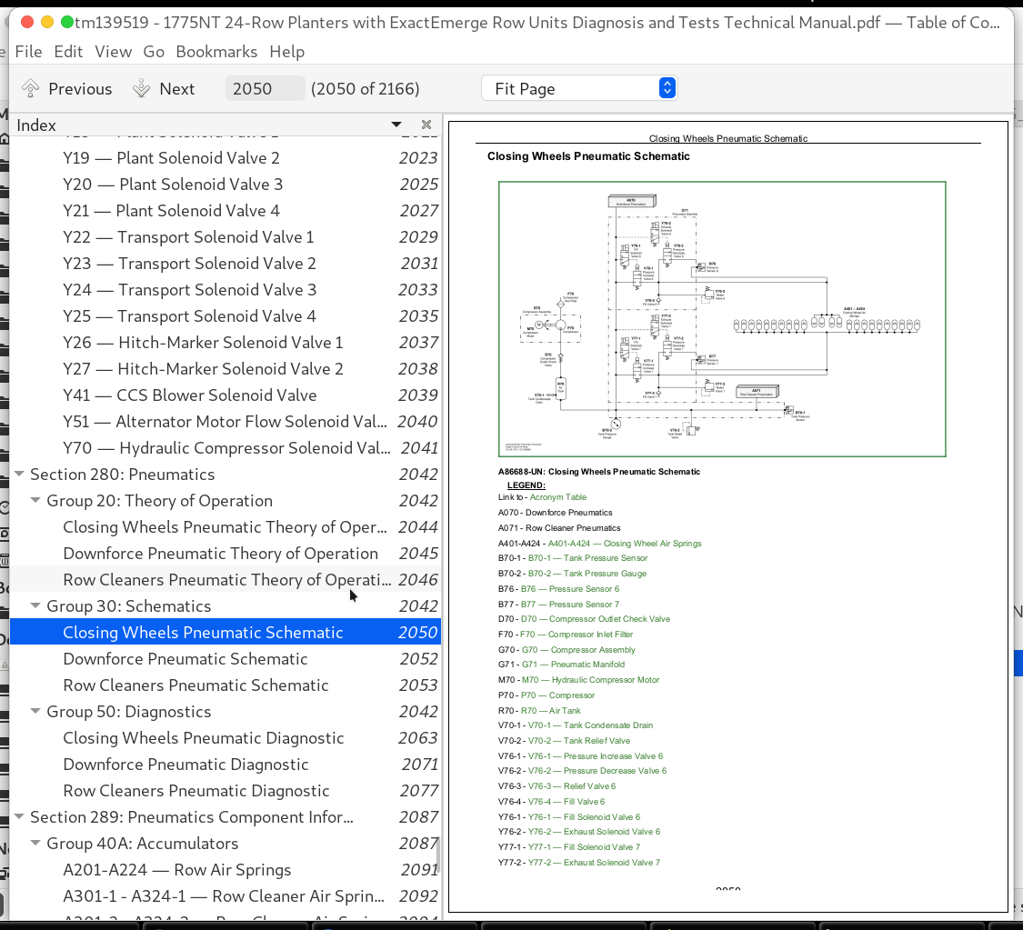
Closing Wheels Pneumatic Schematic
Downforce Pneumatic Schematic
Row Cleaners Pneumatic Schematic
Group 50: Diagnostics
Closing Wheels Pneumatic Diagnostic
Downforce Pneumatic Diagnostic
Row Cleaners Pneumatic Diagnostic
Section 289: Pneumatics Component Information
Group 40A: Accumulators
A201-A224 — Row Air Springs
A301-1 - A324-1 — Row Cleaner Air Springs Down
A301-2 - A324-2 — Row Cleaner Air Springs Up
A401-A424 — Closing Wheel Air Springs
Group 40B: Sensors
B70-1 — Tank Pressure Sensor
B70-2 — Tank Pressure Gauge
B71 — Pressure Sensor 1
B72 — Pressure Sensor 2
B73 — Pressure Sensor 3
B74 — Pressure Sensor 4
B75 — Pressure Sensor 5
B76 — Pressure Sensor 6
B77 — Pressure Sensor 7
Group 40D: Check Valves
D70 — Compressor Outlet Check Valve
Group 40F: Filters
F70 — Compressor Inlet Filter
Group 40G: Assembly Groups
G70 — Compressor Assembly
G71 — Pneumatic Manifold
Group 40P: Pumps
P70 — Compressor
Group 40R: Reservoirs
R70 — Air Tank
Group 40V: Valves
V70-1 — Tank Condensate Drain
V70-2 — Tank Relief Valve
V71-1 — Pressure Increase Valve 1
V71-2 — Pressure Decrease Valve 1
V71-3 — Relief Valve 1
V71-4 — Fill Valve 1
V72-1 — Pressure Increase Valve 2
V72-2 — Pressure Decrease Valve 2
V72-3 — Relief Valve 2
V72-4 — Fill Valve 2
V73-1 — Pressure Increase Valve 3
V73-2 — Pressure Decrease Valve 3
V73-3 — Relief Valve 3
V73-4 — Fill Valve 3
V74-1 — Pressure Increase Valve 4
V74-2 — Pressure Decrease Valve 4
V74-3 — Relief Valve 4
V74-4 — Fill Valve 4
V75-1 — Pressure Increase Valve 5
V75-2 — Pressure Decrease Valve 5
V75-3 — Relief Valve 5
V75-4 — Fill Valve 5
V76-1 — Pressure Increase Valve 6
V76-2 — Pressure Decrease Valve 6
V76-3 — Relief Valve 6
V76-4 — Fill Valve 6
V77-1 — Pressure Increase Valve 7
V77-2 — Pressure Decrease Valve 7
V77-3 — Relief Valve 7
V77-4 — Fill Valve 7
Group 40Y: Solenoid Valves
Y71-1 — Fill Solenoid Valve 1
Y71-2 — Exhaust Solenoid Valve 1
Y72-1 — Fill Solenoid Valve 2
Y72-2 — Exhaust Solenoid Valve 2
Y73-1 — Fill Solenoid Valve 3
Y73-2 — Exhaust Solenoid Valve 3
Y74-1 — Fill Solenoid Valve 4
Y74-2 — Exhaust Solenoid Valve 4
Y75-1 — Fill Solenoid Valve 5
Y75-2 — Exhaust Solenoid Valve 5
Y76-1 — Fill Solenoid Valve 6
Y76-2 — Exhaust Solenoid Valve 6
Y77-1 — Fill Solenoid Valve 7
Y77-2 — Exhaust Solenoid Valve 7
John Deere 16-Row Planter with MaxEmerge 5 Row Units Models 1775NT Diagnosis and Tests Service Technical Manual (TM131519)
![]()