
John Deere 1780 Front-Fold Drawn Conservation Planters Diagnosis and Tests Service Technical Manual (TM1633)

Complete Diagnosis & Tests Technical Manual with electrical wiring diagrams for John Deere 1780 Front-Fold Drawn Conservation Planters, with all the shop information to maintain, diagnostic, repair, and service like professional mechanics.
John Deere Front-Fold Plus Drawn Conservation Planters Models 1780 workshop Diagnosis & Tests technical manual includes:
* Numbered table of contents easy to use so that you can find the information you need fast.
* Detailed sub-steps expand on repair procedure information
* Numbered instructions guide you through every repair procedure step by step.
* Troubleshooting and electrical service procedures are combined with detailed wiring diagrams for ease of use.
* Notes, cautions and warnings throughout each chapter pinpoint critical information.
* Bold figure number help you quickly match illustrations with instructions.
* Detailed illustrations, drawings and photos guide you through every procedure.
* Enlarged inset helps you identify and examine parts in detail.
tm1633 - 1780, 1785 Front-Fold Plus Drawn Conservation Planters Technical Manual.pdf
PRODUCT DETAILS:
Total Pages: 882 pages
File Format: PDF (PC/Mac/Android/Kindle/iPhone/iPad; bookmarked, ToC, Searchable, Printable)
Language: English
MAIN SECTIONS
Foreword
Safety and General Information
Safety
Lubricants
General Information
Planter Frame Adjustments
Welding
Repair And Welding
Planting Units
Vacuum Seed Metering Mechanisms
Plateless Seed Meter Mechanism
Vacuum Manifold System
Seed Openers
Closing Wheels
Insecticide/Herbicide Meter
Coulter
Troubleshooting
Electrical
Specifications
Harness Repair
Control Console Repair
Lighting Repair
Drives
Specifications
Transmissions and Drives
Half Width Disconnect
Liquid Fertilizer
Variable Rate Drive
Wheel Modules and Tires
Wheel Module Repair
Hydraulics
Vacuum Meter
Cylinders
Solenoid Valves
Electrical Operation and Tests
General Information
System Schematics
Planter Operational Checks
System Diagnosis and Tests
System Operations
Drives Operation and Tests
Seed Transmission
Hydraulic System Operation and Tests
General Information
Diagnosis
Theory Of Operation
tm1633 - 1780, 1785 Front-Fold Plus Drawn Conservation Planters
Table of Contents
Foreword
Section 10: Safety and General Information
Group 05: Safety
Recognize Safety Information
Understand Signal Words
Follow Safety Instructions
Handle Fluids Safely—Avoid Fires
Prevent Battery Explosions
Prepare for Emergencies
Operate the Planter Safely
Keep Riders Off Machine
Prevent Machine Runaway
Prevent Acid Burns
Handle Chemical Products Safely
Transport Safely
Use Safety Lights and Devices
Use a Safety Chain
Avoid High-Pressure Fluids
Park Machine Safely
Free Dry Fertilizer Augers Safely
Handle Chemical Products Safely
Support Machine Properly
Wear Protective Clothing
Service Machines Safely
Work In Ventilated Area
Remove Paint Before Welding or Heating
Illuminate Work Area Safely
Avoid Heating Near Pressurized Fluid Lines
Replace Safety Signs
Use Proper Lifting Equipment
Service Tires Safely
Work in Clean Area
Practice Safe Maintenance
Perform Service Safely
Use Proper Tools
Dispose of Waste Properly
Store Attachments Safely
Use Adequate Service Facilities
Insecticide and/or Herbicide Hoppers Lid Fill Closed Handling System
Observe Environmental Protection Regulations
Live With Safety
Group 10: Lubricants
Grease
Gear Oil
Alternative and Synthetic Lubricants
Lubricant for Finger Pickup Meters
Lubricant for Radial Bean Meter Only
Special Lubricants for Vacuum Seed Meters
Lubricant Storage
Group 15: General Information
Service Information Bulletins
Unified Inch Bolt and Screw Torque Values
Metric Bolt and Screw Torque Values
O-Ring Boss Fitting Torque Chart
Service Recommendations for 37° Flare Connectors
Specifications
Tractor Hydraulic System Requirements
Serial Number Location
Dimensions
Dimensions (Unfolded)
Dimensions (Folded)
Dimensions (Unfolded)
Dimensions (Folded)
Group 20: Planter Frame Adjustments
Specifications
Draft Tube Adjustment
Latch Adjustment
Wing Drop Adjustment
Tongue Adjustment
Adjust Frame Height
Countershaft Drive Coupler Adjustment
Section 20: Welding
Group 05: Repair And Welding
Unauthorized Modifications
Frame Repair
Welding
Emergency Crack Repair
Emergency “T” Joint Repair
Skip Welding
Stress Relief (Normalizing)
Section 30: Planting Units
Group 05: Vacuum Seed Metering Mechanisms
Special or Essential Tools
Other Material
Vacuum
Vacuum Meter Operating Characteristics
Use of Talc Lubricant
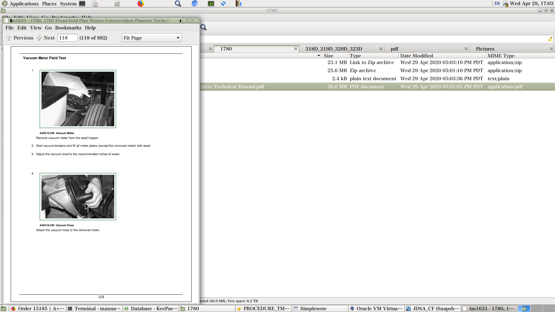
Vacuum Meter Field Test
Diagnosing Vacuum Meter Malfunctions
Vacuum Meter Inspection and Service
Repair Vacuum Seed Meter
Install New Vacuum Seal
Adjust Vacuum Meter Baffle
Check Seed Disk Cell
Install Seed Disk
Adjust Meter Hub
Sugar Beet, Sorghum Seed and Sweet Corn Knockout Wheel
Install Knockout Assembly (Sugar Beets, Sorghum and Sweet Corn)
Select Correct Vacuum Meter Brush
Change Brush
Install Brush
Double Eliminator (Sweet Corn/Edible Bean Disk - Flat Type)
Group 10: Plateless Seed Meter Mechanism
Other Material
Specifications
Plateless General Information
Finger Pickup Metering Unit Operating Characteristics
Diagnosing Finger Pickup Malfunctions
Inspect Finger Pickup Meter
Repair Finger Pickup
Feed Cup Operating Characteristics
Diagnosing Feed Cup Malfunctions
Inspect Feed Cup
Inspect Regular Rate Sorghum Feed Cup
Radial Bean Meter Operating Characteristics
Radial Bean Meter Lubricant
Diagnosing Malfunctions
Radial Bean Meter Inspection and Service
Repair Radial Bean Meter
Group 15: Vacuum Manifold System
Clean Vacuum Manifold System
Repair Vacuum Monitoring Assembly
Repair Vacuum Monitoring Assembly —Two Vacuum Gauges
Repair Vacuum Monitoring Assembly with SeedStar
Group 20: Seed Openers
Special or Essential Tools
Other Material
Specifications
Tru-Vee Double Disk
Changing Planting Depth
Inspect Openers
Adjusting Gauge Wheels
Replacing Seed Opener Blades and Seed Tube Guard
Diagnosing Seed Opener Malfunctions
Tru-Vee Double Disk Opener MaxEmerge Plus Units
Replace Scrapers
Repair Gauge Wheels
Gauge Wheel Bearing Replacement
Walking Gauge Wheel
Group 25: Closing Wheels
Closing Wheels
Adjust Closing Wheel Down Force
Adjust Closing Wheel When Planting Small Seeds at Shallow Depths
Center (Align) Closing Wheels
Closing Wheels—MaxEmerge Plus Units
Group 30: Insecticide/Herbicide Meter
Specifications
Calibrating Insecticide/Herbicide Meter
Insecticide/Herbicide Meter Drive Alignment
Group 35: Coulter
Specifications
Coulter Maintenance
Group 40: Troubleshooting
Row Units
Vacuum Meter
Plateless Meter
Section 40: Electrical
Group 05: Specifications
Electrical Specifications
Group 10: Harness Repair
Essential or Recommended Tools
Service Equipment and Tools
Electrical Tool Repair Kit
Wire Repair Pliers
Terminal Applicator
Other Materials
Service Parts Kits
Connector Identification
Electrical Connector Handling
Replace CPC, Large MATE-N-LOK and METRIMATE CPC, MATE-N-LOK, and METRIMATE are trademarks of AMP Inc. Pin Type Connectors
Replace CPC Blade Type Connectors
Replace Small MATE-N-LOK MATE-N-LOK is a trademark of AMP Inc. Socket Connector
Replace Small MATE-N-LOK MATE-N-LOK is a trademark of AMP Inc. Pin Connector
Replace DEUTSCH DEUTSCH is a trademark of the Deutsch Co. Connectors
Replace WEATHER PACK WEATHER PACK is a trademark of Packard Electric. Connector
Remove Connector Body from Blade Terminals
Install DEUTSCH DEUTSCH is a trademark of the Deutsch Co. Contact
Install WEATHER PACK WEATHER PACK is a trademark of Packard Electric. Contact
Replace (Pull Type) Metri-Pack Connectors
Replace (Push Type) Metri-Pack Connectors
Use Terminal Cleaner and Di-Electric Grease
Harness Repair (Splice Broken or Cut Wire)
Harness Repair—Splice Connector
Replace Harness
Group 15: Control Console Repair
Remove Console—12/23 and 16/22
Remove Console—24/20 and 16/31 Planters
Remove Console—12/23 and 16/22 (30-60 Series Tractors)
Remove Console—12/23 and 16/22 (8000 Series Tractors)
Console Harness—12/23 and 16/22
Repair Console—12/23 and 16/22
Group 20: Lighting Repair
Warning Lamp Repair 12/23 and 16/22 (SN —680100)
Warning Lamp Repair 24/20 and 16/31 (SN —680100)
Red Warning Lamp Repair (SN 680101—)
Amber Warning Lamp Repair (SN 680101—)
Section 50: Drives
Group 05: Specifications
Drive Chains
Fertilizer Drive
Group 10: Transmissions and Drives
Specifications
Seed Transmission
Disassemble and Assemble Seed Transmission
Adjusting Seed Transmission Wheel Engagement Point
Replace Drillshaft Cotter Pin
Group 15: Half Width Disconnect
Other Material
Specifications
Half-Width Disconnect Clutch
Remove Half-Width Disconnect
Sprocket Kit
Cover Kit
Wiring Harness Kit
Coil Kit
Actuator, Hub and Spring Kits
Group 25: Liquid Fertilizer
Other Material
Specifications
Liquid Fertilizer Transmission—12/23 and 16/22
Adjust Seed and/or Fertilizer Transmission Wheel Engagement Point
Pump Orientation
Fertilizer Pump Cross-Sectional Drawing
Liquid Fertilizer System Operation
Priming and Initial Start Up of Pump
How to Set Liquid Fertilizer Rates
Changing From Low to High Range (16-Row)
Changing From High to Low Range (16-Row)
Changing From Low to High Range (12/23)
Changing From High to Low Range (12/23)
Changing Orifice in Special Fitting
Clean Strainer
Strainer Maintenance
Piston Pump Storage Procedures
Flush Fertilizer System
Piston Pump Repair
Check Valves and Install Gasket Kit
Fertilizer Pump Repair Kits
Lubrication
Afterseason Storage
Single-Disk Fertilizer Opener Maintenance
Fertilizer System
Liquid Fertilizer—Piston Pump System
Group 30: Variable Rate Drive
Variable Rate Drive
Section 60: Wheel Modules and Tires
Group 05: Wheel Module Repair
Specifications
Frame Wheels—12/23 (H01780F665101— ) (H01780F670101— )
Frame Wheels—24/20 Planter
Wheel Module—12/23 (H01780F675174—)
Wheel Module—12/23, 16/22 (H01780F675174— ), and 16/31
Section 70: Hydraulics
Group 05: Vacuum Meter
Essential or Recommended Tools
Flywheel Puller Assembly
Other Material
Specifications
Set Vacuum Level
Check Row Vacuum Reading
Inspect Vacuum Motor
Clean Vacuum Pump Motor Guard
Hookup for VacuMeter Using Tractor Valve to Control Blower Speed 8000 and 9000 Series SCV
Hookup for VacuMeter on 8000 and 9000 Series Tractors Using Power Beyond and Planter Valve to Control Blower Speed
Hookup for VacuMeter on 8000 Series Tractor Using SCV's to Control Blower Speed Optional Configuration
Connect Blowers for Vacuum Control (Other Tractors)
Hookup for VacuMeter on 8000 Series Tractor Using Power Beyond and Planter Valves to Control Blower Speed
Hookup for VacuMeter On 8000 Series Tractor for Planter with Independent Markers
Vacuum Blower Control Manual Shut-Off Valve (All Flow Control Valve Versions) Power Beyond Applications
Flow Control Valve
Repair Vacuum Pump
Assemble Pump
Group 10: Cylinders
Essential or Recommended Tools
Ring Compressor
Snap Ring Pliers
Port Wrench
Spanner Wrench
Specifications
Cylinder Specifications
Avoid High-Pressure Fluids
Remove Marker Cylinder—12/23 and 16/22
Remove Marker Cylinder 16/31 and 24/20
Install Marker Cylinder 12/23 and 16/22
Install Marker Cylinder 16/31 and 24/20
Remove Fold Cylinder
Install Fold Cylinder
Remove Hitch Cylinder
Install Hitch Cylinder
Remove Wheel Lift Cylinder
Install Wheel Lift Cylinder
Hitch Cylinder 12/23 and 16/22
Hitch Cylinder 24/20 and 16/31
Marker Cylinder 12/23 and 16/22 Style A
Marker Cylinder 24/20 and 16/31 Style A
Marker Cylinder 12/23, 16/22, 24/20 and 16/31 Style B
Marker Wing Cylinder 24/20 and 16/31
Fold Cylinder
Disassemble Wyr-Loc Cylinder
Assemble Cylinder
Lift Cylinder—12/23 (H01780F665101— ) (H01780F670101— )
Lift Cylinder—12/23 (H01780F675101— ) 12/23 and 16/22 (H01780F675174— ) 24/20 and 16/31 (H01780A670101— ) (H01780A675101— )
Disassemble Lift Cylinder—12/23 (H01780F665101— ) (H01780F670101— )
Assemble Lift Cylinder—12/23 (H01780F665101— ) (H01780F670101— )
Disassemble Lift Cylinder—12/23 (H01780F675101— ) 12/23 and 16/22 (H01780F675174— ) 24/20 and 16/31 (H01780A670101— ) (H01780A675101— )
Assemble Lift Cylinder—12/23 (H01780F675101— ) 12/23 and 16/22 (H01780F675174— ) 24/20 And 16/31 (H01780A670101— ) (H01780A675101— )
Group 15: Solenoid Valves
Specifications
Remove and Install Solenoid Valve
Inspect Valve
Inspect Flow Regulator Valve
Section 240: Electrical Operation and Tests
Group 05: General Information
Electrical Schematic Symbols
Visually Inspect Electrical System
Seven Step Electrical Test Procedure
Circuit Information
Electrical Circuit
Electronic Circuit
Electrical Circuit Malfunctions
High Resistance or Open Circuit
Grounded Circuit
Shorted Circuit
Abbreviations and Explanations—Wiring Diagrams
Communication System Terminators—SeedStar Monitor Controller with Frame Control
Protect Monitor and Control System From High Voltage
Group 10: System Schematics
SeedStar and Variable Rate Drive
Frame Control and Lighting Circuit Schematic—12/23 and 16/22
24/20 and 16/31 Lighting Circuit Schematic (SN 680101—)
Tractor Harness Schematic SN—690100
Communications Cable Connector (Tractor) (1-of-2) (SN—690100)
Communications Cable Connector (Tractor) (2-of-2) (SN—690100)
Test Passive Terminator (SN—690100)
Tractor Harness Schematic (SN 690101—)
Implement Harness Schematic (SN 690101—)
Communications Cable Connector (Tractor) (SN 690101—)
Frame Control Harness Schematic—1780 24/20 and 16/31 Row Planters
12/23 and 16/22 Frame Control and Lighting Harnesses
12/23 and 16/22 ComputerTrak ComputerTrak is a trademark of Deere & Company Monitor Harness
12/23 and 16/22 SeedStar SeedStar is a trademark of Deere & Company Monitor Harness
Frame Control and Lighting Harnesses—24/20 and 16/31
SeedStar Can and Seed Sensor Harness Location—24/20 and 16/31
Console Wiring Harness—12/23 and 16/22
Lighting Enhancement Module—Theory of Operation
Schematic—Lighting Enhancement Module (SN 680101—)
Group 15: Planter Operational Checks
Planter Operational Checks
Group 20: System Diagnosis and Tests
Service Equipment and Tools
Specifications
System Diagnosis—12/23 and 16/22
System Diagnosis—24/20 and 16/31
Planter Control System Tests 16/31 and 24/20
CAN Bus Diagnostics
Planter Control System Tests—12/23 and 16/22
24/20,16/31 SeedStar Controller Pin Functions—Black Connector
Test Console Switches Using SeedStar Display Info Mode 16/31 and 24/20
Test Console Switches—12/23 and 16/22
Test Console Harness—12/23 and 16/22
Checking Solenoids
Checking Valves
Testing Diodes
Test 7-Pin Connector
7-Pin Connector
Test Fold Switch
Test Relays
Diagnosing Failed Relays
Test Marker Alternating Switch
Diagnosing Failed Switches
Group 25: System Operations
Solenoid Operated Check Valve (SV1 and SV3)
Solenoid Operated Shut-Off Valve (SV4)
Valve Block Location
1780 Valve Block—12/23 (H01780F665101—999) (H01780F670101—999)
Switch Position vs Solenoid Status
1780 Valve Block—12/23 (H01780F675101—174)
Switch Position vs Solenoid Status
1780, 1785 Valve Block—12/23 and 16/22 (H01780F675175— )
Switch Position vs Solenoid Status
1780, 1785 Valve Block 24/20 and 16/31 (H01780A670101— )
1780, 1785 Marker Valve Block—24/20 and 16/31
Switch Position Solenoid Status
1780, 1785 Valve Block—24/20 and 16/31 (H01780A675101— )
1780, 1785 Marker Valve Block—24/20 and 16/31
Switch Position Solenoid Status
Section 250: Drives Operation and Tests
Group 05: Seed Transmission
Seed Transmission Theory of Operation
Section 270: Hydraulic System Operation and Tests
Group 05: General Information
JIC Hydraulic Symbols
Commonly Used Planter Hydraulic Symbols
Abbreviations and Explanation
Group 10: Diagnosis
Planter Operational Checks
Diagnosing Uneven Wheel Cylinder Retraction While Lowering—1780, 1785 Front Fold Planters
Flow Regulator Valve Location Diagrams
Flow Regulator Diagnostics
Wing Wheel Fails to Retract (Planter Folded)
1780 12/23 (H01780F665101—999) (H01780F670101—999) Wheel Cylinders Retract When Planter is Raised (Plant Position)
Diagnosing Tractor SCV Leak
Planter Raise Times
Group 25: Theory Of Operation
1780 Hydraulics—12/23 (H01780F665101—999) (H01780F670101—999)
1780 Hydraulics—12/23 (H01780F675101—675174)
1780, 1785 Hydraulics—12/23 and 16/22 (H01780F675175— )
1780 Hydraulics—12/23 (H01780F665101—999) (H01780F670101—999)
1780 Hydraulics—12/23 (H01780F675101—174)
1780, 1785 Hydraulics—12/23 and 16/22 (H01780F675175— )
1780 Hydraulics—24/20 (H01780A670101—999)
1780, 1785 Hydraulics—24/20 (H01780A675101— )
1780, 1785 Hydraulics—16/31 (H01780A670101— )
1780, 1785 Hydraulics—16/31 (H01780A675101— )
Valve Block Location
1780 Valve Block—12/23 (H01780F665101—999) (H01780F670101—999)
12/23—(H01780F665101—999) (H01780F670101—999)
1780 Valve Block—12/23 (H01780F675101—174)
12/23—(H01780F675101—174)
1780, 1785 Valve Block—12/23 and 16/22 (H01780F675175— )
12/23 and 16/22—(H01780F675175— )
1780 Valve Block 24/20 and 16/31 (H01780A670101—999)
24/20 and 16/31 (H01780A670101—999)
1780, 1785 Valve Block—24/20 and 16/31 (H01780A675101— )
24/20 and 16/31 (H01780A675101— )
Flow Regulator Valves
Thermal Relief Valves
Solenoid Operated Check Valve (SV1 and SV3)
Solenoid Operated Shut-Off Valve (SV4)
Solenoid Valves (SV1 and SV3)
Marker Sequence Valve—12/23 and 16/22
Raise Marker—One or Both Markers—12/23 and 16/22
Lower Right Marker—12/23 and 16/22
Lower Left Marker—12/23 and 16/22
Fold Planter—12/23 and 16/22
Unfold Planter—12/23 and 16/22
Retract Hitch Cylinder—12/23 (H01780F665101— ) (H01780F670101— )
Retract Hitch Cylinder—12/23 and 16/22 (H01780F675101— ) (H01780675174— )
Extend Hitch Cylinder—12/23 (H01780F665101— ) (H01780F670101— )
Extend Hitch Cylinder—12/23 and 16/22 (H01780F675101— ) (H01780675174— )
Raise Planter—12/23 and 16/22
Lower Planter—12/23 and 16/22
Extend Wing Wheels—12/23 and 16/22
Retract Wing Wheels—12/23 and 16/22
Lower Marker—12/23 and 16/22
Raise Marker(s)—12/23 and 16/22
Lower Marker Wing(S) 24/20 and 16/22
Raise Marker Wing(S) 24/20 and 16/22
Marker Operation—24/20 and 16/31 Manual Mode
Marker Operation—24/20 and 16/31 Automatic Mode
Lower Planter—16/31 8-Cylinder Lift System
Raise Planter—16/31 8-Cylinder Lift System
Extend Wing Wheels—16/31
Retract Wing Wheels—16/31
Extend Wing Wheels—24/20
Retract Wing Wheels—24/20
Lower Planter—24/20 6-Cylinder Lift System
Raise Planter—24/20 6-Cylinder Lift System
Raise/Lower Hitch—24/20, 16/31
Unfold/Fold Planter—24/20, 16/31
![]()