
John Deere Planters Models 1790 Diagnosis and Tests Service Technical Manual (TM111719)
Complete Diagnosis & Tests Technical Manual with electrical wiring diagrams for John Deere Planters Models 1790 (Worldwide Edition), with all the shop information to maintain, diagnose, and rebuild like professional mechanics.
John Deere 1790 Planter Frames (SN.740101-745000) workshop Diagnosis & Tests technical manual includes:
* Numbered table of contents easy to use so that you can find the information you need fast.
* Detailed sub-steps expand on repair procedure information
* Numbered instructions guide you through every repair procedure step by step.
* Troubleshooting and electrical service procedures are combined with detailed wiring diagrams for ease of use.
* Notes, cautions and warnings throughout each chapter pinpoint critical information.
* Bold figure number help you quickly match illustrations with instructions.
* Detailed illustrations, drawings and photos guide you through every procedure.
* Enlarged inset helps you identify and examine parts in detail.
tm111719 - 1790 Planter Frame Diagnosis and Tests - (740101-) Technical Manual.pdf
tm111719 - 1790 Planter Frame Diagnosis and Tests - (740101-) Technical Manual.epub
Total Pages: 1,104 pages
File Format: PDF/EPUB/MOBI/AZW (PC/Mac/Android/Kindle/iPhone/iPad; bookmarked, ToC, Searchable, Printable)
Language: English
MAIN SECTIONS
Foreword
General Information
Safety
Lubricants
General Information and Specifications
Observable Symptoms
Electrical
Hydraulics
Electrical System
How To Use This Diagnostic Information
Solenoid Sequence Table
Auxiliary Hydraulics
Auxiliary Power
CCS Agitator
CCS Blower
CCS Tank Low Warning
Convenience Outlet
Drawbar Hitch
Field Lift
Fold
Frame Control Console
Half Width Disconnects Type ID
Half Width Disconnects Type A
Half Width Disconnects Type B
Lighting - CCS Fill Lights
Lighting - Transport Lighting EU
Lighting - Transport Lighting NA
Markers
Rockshafts
Transport Lift
Connector Information
Hydraulic System
General Information
Auxiliary Hydraulics
CCS Blower
Drawbar Hitch
Field Lift
Fold
Hydraulic Compressor
Independent Markers
Integrated Markers
Rockshafts
Transport Lift
Vacuum
Variable Rate Drive Type Identification
Variable Rate Drive Type A
Variable Rate Drive Type B
Component Identification
tm111719 - 1790 Planter FrameDiagnosis and Tests -: (740101-)
Table of Contents
Foreword
Section 210: General Information
Group 05: Safety
Recognize Safety Information
Understand Signal Words
Follow Safety Instructions
Handle Fluids Safely—Avoid Fires
Prepare for Emergencies
Avoid Harmful Asbestos Dust
Practice Safe Maintenance
Avoid High-Pressure Fluids
Park Machine Safely
Support Machine Properly
Wear Protective Clothing
Handle Chemical Products Safely
Avoid Contact with Agricultural Chemicals
Clean Vehicle of Hazardous Pesticides
Work in Clean Area
Service Machines Safely
Work In Ventilated Area
Illuminate Work Area Safely
Replace Safety Signs
Use Proper Lifting Equipment
Remove Paint Before Welding or Heating
Avoid Heating Near Pressurized Fluid Lines
Service Tires Safely
Use Proper Tools
Construct Dealer-Made Tools Safely
Decommissioning — Proper Recycling and Disposal of Fluids and Components
Live With Safety
Group 10: Lubricants
Grease
Gear Oil
Alternative and Synthetic Lubricants
Lubricant Storage
Group 15: General Information and Specifications
Service Information Bulletins
Unauthorized Modifications
Machine Photo
Machine Specifications
Record Serial Number
Metric Bolt and Cap Screw Torque Values
Unified Inch Bolt and Cap Screw Torque Values
Service Recommendations For O-Ring Boss Fittings
Face Seal Fittings Assembly and Installation—All Pressure Applications
Metric Face Seal Fitting Torque Chart—Standard Pressure Applications
SAE Face Seal Fitting Torque Chart—Standard Pressure Applications
External Hexagon Port Plug Torque Chart
Service Recommendations For 37° Flare and 30° Cone Seat Connectors
Section 212: Observable Symptoms
Group 240: Electrical
Auxiliary Hydraulics Diagnostics
Auxiliary Power Diagnostics
CCS Agitator Diagnostics
CCS Blower Diagnostics
CCS Tank Low Warning Diagnostics
Convenience Outlet Diagnostics
Drawbar Hitch Diagnostics
Field Lift Diagnostics
Fold Diagnostics
Frame Control Console Diagnostics
Half-Width Disconnects Diagnostics
Lighting — CCS Fill Lights Diagnostics
Lighting — Transport Lighting EU Diagnostics
Lighting — Transport Lighting NA Diagnostics
Markers Diagnostics
Rockshafts Diagnostics
Transport Lift Diagnostics
Group 270: Hydraulics
Auxiliary Hydraulics Diagnostics
CCS Blower Diagnostics
Drawbar Hitch Diagnostics
Field Lift Diagnostics
Fold Diagnostics
Hydraulic Compressor Diagnostics
Independent Markers Diagnostics
Integrated Markers Diagnostics
Rockshafts Diagnostics
Transport Lift Diagnostics
Vacuum Diagnostics
Variable Rate Drive Diagnostics
Section 240: Electrical System
Group 5: How To Use This Diagnostic Information
General Information
Group 10: Solenoid Sequence Table
Solenoid Sequence Table
Group 15A: Auxiliary Hydraulics
Auxiliary Hydraulics Electrical Theory of Operation
Auxiliary Hydraulics Electrical Schematic
Auxiliary Hydraulics Electrical Diagnostics
Group 15B: Auxiliary Power
Auxiliary Power Electrical Theory of Operation
Auxiliary Power Electrical Schematic
Auxiliary Power Electrical Diagnostics
Group 15C: CCS Agitator
CCS Agitator Electrical Theory of Operation
CCS Agitator Electrical Schematic
CCS Agitator Electrical Diagnostics
Group 15D: CCS Blower
CCS Blower Electrical Theory of Operation
CCS Blower Electrical Schematic
CCS Blower Electrical Diagnostics
Group 15E: CCS Tank Low Warning
CCS Low Tank Warning Electrical Theory of Operation
CCS Low Tank Warning Electrical Schematic
CCS Low Tank Warning Electrical Diagnostics
Group 15F: Convenience Outlet
Convenience Outlet Electrical Theory of Operation
Convenience Outlet Electrical Schematic
Convenience Outlet Electrical Diagnostics
Group 15G: Drawbar Hitch
Drawbar Hitch Electrical Theory of Operation
Drawbar Hitch Electrical Schematic
Drawbar Hitch Electrical Diagnostics
Group 15H: Field Lift
Field Lift Electrical Theory of Operation
Field Lift Electrical Schematic
Field Lift Electrical Diagnostics
Group 15I: Fold
Fold Electrical Theory of Operation
Fold Electrical Schematic
Fold Electrical Diagnostics
Group 15J: Frame Control Console
Frame Control Console Electrical Theory of Operation
Frame Control Console Electrical Schematic
Frame Control Console Electrical Diagnostics
Group 15K: Half Width Disconnects Type ID
Half-Width Disconnects Diagnostics Type Identification
Group 15L: Half Width Disconnects Type A
Half-Width Disconnects Type A Electrical Theory of Operation
Half-Width Disconnects Type A Electrical Schematic
Half-Width Disconnects Type A Electrical Diagnostics
Group 15M: Half Width Disconnects Type B
Half Width Disconnects Type B Electrical Theory of Operation
Half Width Disconnects Type B Electrical Schematic
Half Width Disconnects Type B Electrical Diagnostics
Group 15N: Lighting - CCS Fill Lights
Lighting—CCS Fill Lights Electrical Theory of Operation
Lighting—CCS Fill Lights Electrical Schematic
Lighting—CCS Fill Lights Electrical Diagnostics
Group 15O: Lighting - Transport Lighting EU
Lighting - Transport Lighting EU Electrical Theory of Operation
Lighting - Transport Lighting EU Electrical Schematic
Lighting - Transport Lighting EU Electrical Diagnostics
Group 15P: Lighting - Transport Lighting NA
Lighting - Transport Lighting NA Electrical Theory of Operation
Lighting - Transport Lighting NA Electrical Schematic
Lighting - Transport Lighting NA Electrical Diagnostics
Group 15Q: Markers
Markers Electrical Theory of Operation
Markers Electrical Schematic
Markers Electrical Diagnostics
Group 15R: Rockshafts
Rockshafts Electrical Theory of Operation
Rockshafts Electrical Schematic
Rockshafts Electrical Diagnostics
Group 15S: Transport Lift
Transport Lift Electrical Theory of Operation
Transport Lift Electrical Schematic
Transport Lift Electrical Diagnostics
Group 20: Connector Information
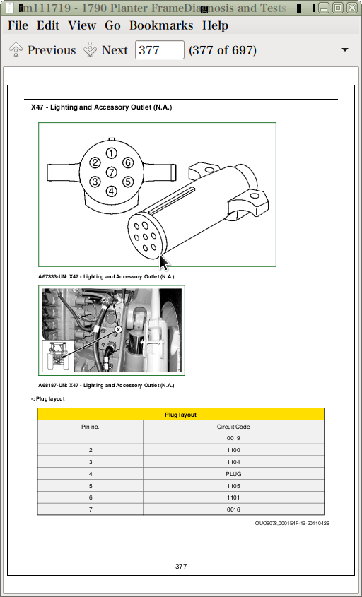
X47 - Lighting and Accessory Outlet (N.A.)
X48 - Lighting and Accessory Outlet (E.U.)
X104 - Convenience Plug 1
X105 - Convenience Plug 2
X106 - Convenience
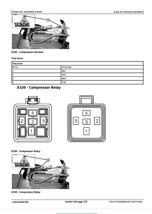
X108 - Compressor Harness
X109 - Compressor Relay
X110 - Compressor Motor
X111 - CAN Draft Tube Harness
X112 - Hitch—Markers Switch Power
X113 - Hitch—Markers Switch Solenoid Power
X114 - Drawbar Hitch Console Harness
X115 - Hitch Console Harness Convenience Plug
X116 - Drawbar Hitch Extension Harness
X117 - Hitch—Marker Solenoid 1
X118 - Hitch—Marker Solenoid 2
X201 - Frame Control Console
X202 - Frame Control Extension Harness
X203 - Frame Draft Tube Harness
X204 - Lights Extension Harness
X205 - Frame Control Fuse
X400 - Left Wing B
X401 - Right Wing B
X402 - Row Switch Adapter Harness
X406 - Fold Switch 3 Diode
X407 - Fold Switch 1
X408 - Fold Switch 2
X409 - Fold Switch 3
X415 - Rear Hitch Harness
X416 - Rear Lights
X417 - Row Switch
X420 - Valve Manifold Harness
X421 - Plant Solenoid 4
X422 - Transport Solenoid 4
X423 - Main Fold Solenoid
X424 - Transport Solenoid 3
X425 - Plant Solenoid 3
X426 - Center Frame Solenoid
X427 - Rockshaft Solenoid 2
X428 - Plant Solenoid 1
X429 - Transport Solenoid 1
X430 - Right Marker Solenoid
X431 - Transport Solenoid 2
X432 - Left Marker Solenoid
X433 - Plant Solenoid 2
X434 - Auxiliary Fold Solenoid
X435 - Rockshaft Solenoid 1
X500 - SMVR
X501 - Lighting Module
X502 - Auxiliary Power 2
X503 - Plant Relay
X504 - Transport Relay
X505 - Agitator Relay
X513 - Seedstar Meter Master Control Unit J2
X515 - Seedstar Primary Control Unit J1
X517 - Seedstar Secondary Control Unit
X520 - CCS Cradle Harness
X521 - CCS Fill Lights
X522 - CCS Blower Solenoid
X523 - Left Bin Level Sensor
X524 - Right Bin Level Sensor
X525 - Left Agitator Motor
X526 - Left Agitator Motor Ground
X527 - Right Agitator Motor
X528 - Right Agitator Motor Ground
X529 - Left Lights Harness
X530 - Left Red Tail Lamp
X531 - Left Amber Hazard Lamp
X532 - Right Lights Harness
X533 - Right Red Tail Lamp
X534 - Right Amber Hazard Lamp
X540 - Ladder Harness
X541 - CCS Light Switch
X542 - Left CCS Lamp
X543 - Right CCS Lamp
X544 - Auxiliary Hydraulics
X550 - Front Cradle Harness
X551 - Clean Out Switch
X552 - Front Bin Level Sensor
X553 - Front Agitator Motor
X554 - Front Agitator Motor Ground
X555 - E11 Left Red Tail Lamp (EU)
X556 - E10 Left Amber Hazard Lamp (EU)
X557 - E12 Right Red Tail Lamp (EU)
X558 - E13 Right Amber Hazard Lamp (EU)
X700 - Rear Backbone Harness
X701 - CIS LCL
X702 - CIS RCL
X708 - Variable Rate Drive 1 Adapter Harness
X726 - LCL
X728 - RCL
X741 - LCL Diode
X742 - RCL Diode
X800 - Right Wing A
X803 - Rockshaft Adapter Harness
X804 - Dimmer Switch
X805 - Anti-Fold Switch
X806 - Rockshaft Switch
Section 270: Hydraulic System
Group 5: General Information
General Information
Group 15A: Auxiliary Hydraulics
Auxiliary Hydraulics Hydraulic Theory of Operation
Auxiliary Hydraulics Hydraulic Schematic
Auxiliary Hydraulics Hydraulic Diagnostics
Group 15B: CCS Blower
CCS Blower Hydraulic Theory of Operation
CCS Blower Hydraulic Schematic
CCS Blower Hydraulic Diagnostics
Group 15C: Drawbar Hitch
Drawbar Hitch Hydraulic Theory of Operation
Drawbar Hitch Hydraulic Schematic
Drawbar Hitch Hydraulic Diagnostics
Group 15D: Field Lift
Field Lift Hydraulic Theory of Operation
Field Lift Hydraulic Schematic
Field Lift Hydraulic Diagnostics
Group 15E: Fold
Fold Hydraulic Theory of Operation
Fold Hydraulic Schematic
Fold Hydraulic Diagnostics
Group 15F: Hydraulic Compressor
Compressor Hydraulic Theory of Operation
Compressor Hydraulic Schematics
Compressor Hydraulic Diagnostics
Group 15G: Independent Markers
Independent Markers Hydraulic Theory of Operation
Independent Markers Hydraulic Schematic
Independent Markers Hydraulic Diagnostics
Group 15H: Integrated Markers
Integrated Markers Hydraulic Theory of Operation
Integrated Markers Hydraulic Schematic
Integrated Markers Hydraulic Diagnostics
Group 15I: Rockshafts
Rockshafts Hydraulic Theory of Operation
Rockshafts Hydraulic Schematic
Rockshafts Hydraulic Diagnostics
Group 15J: Transport Lift
Transport Lift Hydraulic Theory of Operation
Transport Lift Hydraulic Schematic
Transport Lift Hydraulic Diagnostics
Group 15K: Vacuum
Vacuum Hydraulic Theory of Operation
Vacuum Hydraulic Schematic
Vacuum Hydraulic Diagnostics
Group 15L: Variable Rate Drive Type Identification
Variable Rate Drive Type Identification
Group 15M: Variable Rate Drive Type A
Variable Rate Drive Type A Hydraulic Theory of Operation
Variable Rate Drive Type A Hydraulic Schematic
Variable Rate Drive Type A Hydraulic Diagnostics
Group 15N: Variable Rate Drive Type B
Variable Rate Drive Type B Hydraulic Theory of Operation
Variable Rate Drive Type B Hydraulic Schematic
Variable Rate Drive Type B Hydraulic Diagnostics
Group 20: Component Identification
Valve Manifold Components
Hydraulic Components
John Deere Planters Models 1790 Diagnosis and Tests Service Technical Manual (TM111719)
![]()