
John Deere Planters Models 1795 with ExactEmerge Row Units Diagnosis and Tests Service Technical Manual (TM139619)
Complete Diagnosis & Tests Technical Manual with electrical wiring diagrams for John Deere 1795 Planters with Exact Emerge Row Units (SN.765101-), with all the workshop information to maintain, diagnose, repair, and rebuild like professional mechanics.
John Deere Planters Models 1795 with ExactEmerge Row Units workshop Diagnosis & Tests technical manual includes:
* Numbered table of contents easy to use so that you can find the information you need fast.
* Detailed sub-steps expand on repair procedure information
* Numbered instructions guide you through every repair procedure step by step.
* Troubleshooting and electrical service procedures are combined with detailed wiring diagrams for ease of use.
* Notes, cautions and warnings throughout each chapter pinpoint critical information.
* Bold figure number help you quickly match illustrations with instructions.
* Detailed illustrations, drawings and photos guide you through every procedure.
* Enlarged inset helps you identify and examine parts in detail.
tm139619 - 1795 Planters with Electric Drive Diagnosis and Tests Technical Manual.pdf
tm139619 - 1795 Planters with Electric Drive Diagnosis and Tests Technical Manual.epub
Total Pages: 2,132 pages
File Format: PDF/EPUB/MOBI/AZW (PC/Mac/Android/Kindle/iPhone/iPad; bookmarked, ToC, Searchable, Printable)
Language: English
MAIN SECTIONS
Foreword
General Information
How to Use This Manual
Safety
Lubricants
Recommended Tools for Diagnostics
Basic Diagnostics
Diagnostic Information for Electrical Components
Diagnostic Information for Hydraulic Components
Maintaining Hydraulic Systems and Components
Standard Torque Chart Procedures
Acronym Table
Diagnostic Trouble Codes
Accessing Diagnostic Trouble Codes
Electric Power Generation (EPG) Codes
Inertial Measurement Unit (IMU) Codes
JDLink (JDL) Codes
Meter Master Controller (MMC) Codes
Planter Assist Controller (PAC) Codes
Row Cleaner Control (RCC) Codes
Row Unit Controller (RUC) Codes
Observable Symptom and System Diagnostics
Observable Symptoms
Electrical
General Information
Theory of Operation
Schematics - Frame
56 Volt Power Electrical Schematics
CAN Bus Electrical Schematics
High Current Power Electrical Schematics
Diagnostic Tests and Adjustments
Electronic Control Units
General Information
Diagnostic Addresses by Control Unit
Diagnostic Tests
Electrical Component Information
Electrical Assemblies
Sensors
Lights
Fuses
Charging
Relays
Motors
Resistors
Switches
Diodes
Interconnects and Ground Points
Electronically Actuated Mechanical Devices
Hydraulics
General Information
Theory of Operation
Schematic
Diagnostic Tests and Adjustments
Hydraulics Component Information
Accumulators
Sensor or Gauge
Cylinder, Actuator, or Piston
Check Valve
Filter
Valve Block, Assembly, or Gearcase
Cooler
Motor
Orifice
Reservoir or Tank
Valve
Diagnostic Receptacle or Coupler
Solenoid Valve
Pneumatics
Theory of Operation
Schematics
Diagnostics
Pneumatics Component Information
Accumulators
Sensors
Check Valves
Filters
Assembly Groups
Pumps
Reservoirs
Valves
Solenoid Valves
TABLE OF CONTENTS................1
Section 210: General Information................39
Group 5A: How to Use This Manual................39
Information is Available in Sections, Groups and Subgroups................43
Group 5B: Safety................39
Work In Ventilated Area................45
Recognize Safety Information................46
Avoid Backover Accidents................47
Prevent Machine Runaway................48
Avoid Contact with Agricultural Chemicals................49
Clean Vehicle of Hazardous Pesticides................51
Use a Safety Chain................52
Work in Clean Area................53
Decommissioning — Proper Recycling and Disposal of Fluids and Components................54
Prepare for Emergencies................55
In Case of Fire................56
Use Safety Lights and Devices................57
Avoid High-Pressure Fluids................58
Use Proper Lifting Equipment................59
Illuminate Work Area Safely................60
Live With Safety................61
Support Machine Properly................62
Freeing a Mired Machine................63
Protect Against Noise................64
Remove Paint Before Welding or Heating................65
Park Machine Safely................66
Prevent Acid Burns................67
Follow Safety Instructions................69
Use Proper Tools................70
Keep Riders Off Machine................71
Service Tires Safely................72
Stay Clear of Rotating Drivelines................73
Construct Dealer-Made Tools Safely................74
Practice Safe Maintenance................75
Understand Signal Words................77
Replace Safety Signs................78
Prevent Battery Explosions................79
Protect Against High Pressure Spray................80
Avoid Heating Near Pressurized Fluid Lines................81
Tow Loads Safely................82
Transport Towed Equipment at Safe Speeds................83
Observe Maximum Transport Speed................85
Wear Protective Clothing................86
Precautions for Welding................87
Handle Agricultural Chemicals Safely................89
Service and Operate Chemical Sprayers Safely................91
Relieve Hydraulic Pressure Safely................93
Use Steps and Handholds Correctly................94
Group 5C: Lubricants................40
Grease................96
Gear Oil................97
Alternative and Synthetic Lubricants................98
Lubricant Storage................99
Group 5D: Recommended Tools for Diagnostics................40
Recommended Tools................102
Group 5E: Diagnostic Philosophy................40
Basic Diagnostic Philosophy................107
Systematic Diagnostic Approach Overview................110
Troubleshooting Unresolved Problems................114
Group 5F: Diagnostic Information for Electrical Components................40
Electrical Designators................625
Visually Inspect Electrical System................626
Group 5G: Diagnostic Information for Hydraulic Components................1754
Hydraulic Designators................1748
Troubleshooting Tips................121
Visually Inspect Hydraulic System................1750
Group 5H: Maintaining Hydraulic Systems and Components................41
Hydraulic Components................1754
Oil Storage and Filling................1755
Oil Filtration................1756
Group 5I: Standard Torque Chart Procedures................41
Unified Inch Bolt and Screw Torque Values................130
Metric Bolt and Screw Torque Values................132
Group 5J: Acronym Table................136
Acronym Table................136
Section 211: Diagnostic Trouble Codes................138
Group 10A: Accessing Diagnostic Trouble Codes................153
Accessing Diagnostic Trouble Codes................153
Group 10B: Closing Wheel Controller (CWC) Codes................138
CWC 001351.14 - Air Supply System................138
CWC 001387.00 - System control disabled................138
CWC 001387.01 - System control disabled................138
CWC 001387.03 - Closing Wheel Control System................138
CWC 001387.04 - Closing Wheel Control System................138
CWC 001387.10 - System control disabled................138
CWC 001387.13 - Closing Wheel Control System................138
CWC 001387.14 - Closing Wheel Control System................138
CWC 001387.16 - Pressure too high on Closing Wheel Group 1................138
CWC 001387.17 - Moderate leak detected on Closing Wheel Group 1................138
CWC 001388.00 - System control disabled................138
CWC 001388.01 - System control disabled................138
CWC 001388.03 - Closing Wheel Control System................138
CWC 001388.04 - Closing Wheel Control System................138
CWC 001388.10 - System control disabled................138
CWC 001388.13 - Closing Wheel Control System................138
CWC 001388.14 - Closing Wheel Control System................138
CWC 001388.16 - Pressure too high on Closing Wheel Group 2................138
CWC 001388.17 - Moderate leak detected on Closing Wheel Group 2................138
CWC 003509.03 - Sensor Voltage is above Normal................138
CWC 003509.04 - Sensor Voltage is below Normal................138
CWC 517151.01 - Closing Wheel Control System................138
CWC 517151.03 - Closing Wheel Control System................138
CWC 517151.04 - Closing Wheel Control System................138
CWC 517151.05 - Closing Wheel Control System................138
CWC 517151.06 - Closing Wheel Control System................138
CWC 517151.12 - Closing Wheel Control System................138
CWC 517152.03 - Closing Wheel Control System................138
CWC 517152.04 - Closing Wheel Control System................138
CWC 517152.12 - Closing Wheel Control System................139
CWC 517153.01 - Closing Wheel Control System................139
CWC 517153.03 - Closing Wheel Control System................139
CWC 517153.04 - Closing Wheel Control System................139
CWC 517153.05 - Closing Wheel Control System................139
CWC 517153.06 - Closing Wheel Control System................139
CWC 517153.12 - Closing Wheel Control System................139
CWC 517154.03 - Closing Wheel Control System................139
CWC 517154.04 - Closing Wheel Control System................139
CWC 517154.12 - Closing Wheel Control System................139
CWC 517154.31 - Closing Wheel Control System................139
CWC 520463.03 - Closing Wheel Control ECU Power................139
CWC 520463.04 - Closing Wheel Control ECU Power................139
CWC 523218.03 - Valve Power 2 Voltage Above Normal................139
CWC 523218.04 - Closing Wheel Control Valve Power 2................139
CWC 523218.05 - Closing Wheel Control Valve Power 2................139
CWC 523438.02 - EEPROM Checksum Error................139
CWC 523438.14 - EEPROM Out of Bounds Error................139
Group 10C: Electric Power Generation (EPG) Codes................139
EPG 000158.00 - ECU 12 Volt Supply Out of Range High................139
EPG 000158.01 - ECU 12 Volt Supply Out of Range Low................139
EPG 000167.00 - 56 Volt Bus Error................139
EPG 000167.01 - Planter 56 V Bus Too Low for Operation................139
EPG 000167.03 - 56 Volt Bus Voltage Sense Line Issue................139
EPG 000167.17 - Planter 56 V Bus Too Low for Good Performance................139
EPG 000186.01 - PTO Not Engaged or Not Spinning While Engaging Alternator................139
EPG 000444.01 - Depleted High Voltage Battery Bank Detected................139
EPG 000444.03 - Battery Bank Voltage Sense Line Issue................139
EPG 000444.04 - Excessive Battery Bank Discharge Detected................139
EPG 000444.17 - Excessive Usage of Battery Bank During Planting Detected................139
EPG 000444.18 - Low High Voltage Battery Bank Detected................139
EPG 000589.00 - Planter Power Generation Alternator Over Speed Detected................139
EPG 001762.00 - Hydraulic Pressure Sensor Signal Out of Range High................139
EPG 001762.01 - Hydraulic Pressure Sensor Signal Out of Range Low................140
EPG 001762.05 - Missing Hydraulic Pressure Sensor Signal................140
EPG 001762.07 - Hydraulic Pressure Not Detected................140
EPG 002197.08 - Seed Monitor Online but Not Responding to CAN Messages................140
EPG 002197.09 - Seed Monitor Controller is Offline................140
EPG 002197.19 - External User Command Synchronization Error Detected................140
EPG 002634.05 - Battery Contactor Failed to Close................140
EPG 002634.06 - Battery Contactor Failed to Open................140
EPG 003380.00 - Tractor Voltage Supply is High................140
EPG 003380.01 - Alternator Excitation Voltage Low................140
EPG 003380.17 - Alternator Excitation Voltage Low................140
EPG 516207.03 - 56 Volt Alternator Relay................140
EPG 516207.05 - 56 Volt Alternator Relay................140
EPG 516207.06 - 56 Volt Alternator Relay................140
EPG 516207.16 - 56 Volt Alternator Relay................140
EPG 516207.17 - 56 Volt Alternator Relay................140
EPG 516207.18 - 56 Volt Alternator Relay................140
EPG 517131.00 - PTO Power Generation................140
EPG 517131.01 - PTO Power Generation................140
EPG 517131.15 - PTO Power Generation................140
EPG 517131.16 - PTO Power Generation................140
EPG 520440.05 - Battery Contactor Open Circuit Fault Detected................140
EPG 520440.06 - Battery Contactor Short Circuit Fault Detected................140
EPG 520440.07 - Battery Energy Storage................140
EPG 521065.00 - 56 V Load Current Sensor Outside of Expected Operation Range................140
EPG 521065.01 - 56 V Load Current Sensor Zero Value Out of Range................140
EPG 521065.02 - 56 V Load Current Sensor Signal Erratic................140
EPG 521065.05 - 56 V Load Current Sensor Signal Missing................140
EPG 521065.10 - High Voltage Load Current Sensor Installed Backwards................140
EPG 521983.00 - ELX 12 Volt Supply Out of Range High................140
EPG 521983.01 - ELX 12 Volt Supply Out of Range Low................140
EPG 523652.07 - 56 V Load Current Sensor Harness Issue................140
EPG 524010.03 - Flow Control Valve HSD Short to Battery................140
EPG 524010.04 - Valve Power Voltage Below Minimum Voltage Required................141
EPG 524010.06 - Flow Control Valve HSD Short to Ground................141
EPG 524010.106 - Flow Control Valve LSD Short to Ground................141
EPG 524010.17 - Flow Control Valve LSD Open Circuit................141
EPG 524010.18 - Flow Control Valve LSD Short to Battery................141
EPG 524039.00 - Power Generation Hydraulic Motor Over Speed Detected................141
EPG 524039.01 - Power Generation Hydraulic Motor Speed Signal Missing................141
EPG 524039.11 - Hydraulic Motor Failed to Reach Soft Start Exit Conditions................141
EPG 524039.16 - Power Generation Hydraulic Motor Spinning Uncommanded................141
EPG 524039.18 - Power Generation Hydraulic Motor Unable to Achieve Target Speed................141
Group 10D: Inertial Measurement Unit (IMU) Codes................141
IMU 520870.02 - EEPROM Checksum Error................141
IMU 521396.12 - Gyroscope Sensor................141
Group 10E: JDLink (JDL) Codes................141
JDLink Diagnostic Trouble Codes................273
Group 10F: Meter Master Controller (MMC) Codes................141
MMC 000046.03 - Air Supply System................141
MMC 000046.06 - Air Supply System................141
MMC 000046.13 - Air Supply System................141
MMC 000046.14 - Air Supply System................141
MMC 000084.09 - Wheel Speed Not Detected On CAN Bus................141
MMC 000444.04 - Battery Potential (Voltage) / Power Input 2 Low Voltage................141
MMC 000609.02 - The following Row Unit Controllers are not responding to CAN bus commands................141
MMC 000609.12 - The Following Row Unit Controllers are Offline................141
MMC 000628.02 - MMC EOL Data Revision Mismatch................141
MMC 000639.12 - CAN Bus 1 Communication System................141
MMC 000639.14 - CAN Bus 1 Communication System................141
MMC 000705.03 - These Rows Have a Downforce Sensor Error................141
MMC 000705.04 - These Rows Have a Downforce Sensor Error................141
MMC 000705.13 - Gauge Wheel Downforce Sensor Problem................141
MMC 000705.14 - Gauge Wheel and Vacuum Sensor Configuration is Reset................141
MMC 000838.02 - These Row Unit Controllers Have an Addressing Error................141
MMC 000838.03 - These Row Unit Controllers Have an Addressing Error................142
MMC 000838.04 - These Row Unit Controllers Have an Addressing Error................142
MMC 001231.12 - CAN Bus 2 Communication System................142
MMC 001231.14 - CAN Bus 2 Communication System................142
MMC 001235.12 - CAN Bus 3 Communication System................142
MMC 001235.14 - CAN Bus 3 Communication System................142
MMC 001351.03 - Air Supply System................142
MMC 001351.04 - Air Supply System................142
MMC 001351.06 - Air Supply System................142
MMC 001351.14 - Compressor Motor Time Limit Exceeded................142
MMC 001351.16 - Air Supply System................142
MMC 001351.17 - Air Supply System................142
MMC 001351.18 - Air Supply System................142
MMC 001859.09 - Radar Speed Not Detected On CAN Bus................142
MMC 001859.10 - Ground Speed and Tractor Speed Conflict................142
MMC 003132.00 - Fertilizer Pressure Sensor 1 High................142
MMC 003132.03 - Fertilizer Pressure Sensor 1 Short................142
MMC 003132.06 - Fertilizer Pressure Sensor 1 Short................142
MMC 003132.13 - Fertilizer Pressure Sensor 1 Calibration Error................142
MMC 003132.14 - Fertilizer Pressure Sensor 1 Calibration Error................142
MMC 003509.03 - 5 Volt Sensor Supply Voltage High................142
MMC 003509.04 - 5 Volt Sensor Supply Voltage Low................142
MMC 003510.03 - These Row Unit Controllers Have a Sensor Supply Error................142
MMC 003510.04 - These Row Unit Controllers Have a Sensor Supply Error................142
MMC 003510.05 - 5 Volt Sensor Supply Current Low................142
MMC 003510.06 - 5 Volt Sensor Supply Current High................142
MMC 005109.02 - CAN Bus Communication System Problem................142
MMC 005109.12 - CAN Bus Communication System Problem................142
MMC 005109.14 - CAN Bus Communication System Problem................142
MMC 005121.02 - CAN Bus 1 Communication System................142
MMC 005347.12 - These Rows Have an Accelerometer Error................142
MMC 516249.03 - These Row Unit Controllers Have a 3.3 Volt Bus Error................142
MMC 516249.04 - These Row Unit Controllers Have a 3.3 Volt Bus Error................142
MMC 516781.03 - Hydraulic Pressure Problem................143
MMC 516781.04 - Hydraulic Pressure Problem................143
MMC 516781.12 - Hydraulic Pressure Problem................143
MMC 516781.17 - Low Hydraulic Supply Pressure on the Following Rows................143
MMC 517156.01 - Hydraulic Downforce System Issue on the Following Rows................143
MMC 517156.03 - Row Unit Downforce................143
MMC 517156.04 - Row Unit Downforce................143
MMC 517156.12 - Row Unit Downforce................143
MMC 517156.15 - Hydraulic Downforce System Issue on the Following Rows................143
MMC 517156.17 - Hydraulic Downforce System Issue on the Following Rows................143
MMC 517157.01 - Row Unit Downforce................143
MMC 517157.03 - Row Unit Downforce................143
MMC 517157.04 - Row Unit Downforce................143
MMC 517157.05 - Row Unit Downforce................143
MMC 517157.06 - Row Unit Downforce................143
MMC 520462.03 - These Row Unit Controllers Have a 56 Volt Bus Error................143
MMC 520462.04 - These Row Unit Controllers Have a 56 Volt Bus Error................143
MMC 520463.03 - These Row Unit Controllers Have a 12 Volt Bus Error................143
MMC 520463.04 - These Row Unit Controllers Have a 12 Volt Bus Error................143
MMC 520970.02 - Seed Metering System Issue on the Following Rows................143
MMC 520970.03 - Seed Metering System Issue on the Following Rows................143
MMC 520970.04 - Seed Metering System Issue on the Following Rows................143
MMC 520970.05 - Seed Metering System Issue on the Following Rows................143
MMC 520970.06 - Seed Metering System Issue on the Following Rows................143
MMC 520970.07 - Meter Jam on the Following Rows................143
MMC 520970.08 - These Row Unit Controllers Have an Internal Communication Error................143
MMC 520970.12 - These Row Unit Controllers Have a Meter Motor Alignment Error................143
MMC 520970.16 - Seed Metering System Issue on the Following Rows................143
MMC 520970.18 - Seed Metering System Issue on the Following Rows................143
MMC 520973.02 - Seed Delivery System Issue on the Following Rows................143
MMC 520973.03 - Seed Delivery System Issue on the Following Rows................143
MMC 520973.04 - Seed Delivery System Issue on the Following Rows................143
MMC 520973.05 - Seed Delivery System Issue on the Following Rows................143
MMC 520973.06 - Seed Delivery System Issue on the Following Rows................144
MMC 520973.08 - These Row Unit Controllers Have an Internal Communication Error................144
MMC 520973.12 - These Row Unit Controllers Have a Brush Motor Alignment Error................144
MMC 520973.16 - Seed Delivery System Issue on the Following Rows................144
MMC 520973.18 - Seed Delivery System Issue on the Following Rows................144
MMC 520975.02 - The Following Rows Have a Seed Sensor or Harness Issue................144
MMC 520975.03 - The Following Rows Have a Seed Sensor or Harness Issue................144
MMC 520975.04 - The Following Rows Have a Seed Sensor or Harness Issue................144
MMC 520975.05 - The Following Rows Have a Seed Sensor or Harness Issue................144
MMC 520975.06 - The Following Rows Have a Seed Sensor or Harness Issue................144
MMC 520975.07 - The Following Rows Have a Seed Sensor or Harness Issue................144
MMC 520975.16 - The Following Rows Have a Seed Sensor or Harness Issue................144
MMC 521037.03 - These Rows Have a Vacuum Sensor Error................144
MMC 521037.04 - These Rows Have a Vacuum Sensor Error................144
MMC 521037.13 - Seed Vacuum Sensor Problem................144
MMC 521087.03 - Pneumatic Downforce System Group 2................144
MMC 521087.04 - Pneumatic Downforce System Group 2................144
MMC 521087.06 - Pneumatic Downforce System Group 2................144
MMC 521087.16 - Pneumatic Downforce System Group 2................144
MMC 521087.17 - Pneumatic Downforce System Group 2................144
MMC 521087.18 - Pneumatic Downforce System Group 2................144
MMC 521092.03 - Pneumatic Downforce System Group 2................144
MMC 521092.04 - Pneumatic Downforce System Group 2................144
MMC 521092.06 - Pneumatic Downforce System Group 2................144
MMC 521092.16 - Pneumatic Downforce System Group 2................144
MMC 521092.17 - Pneumatic Downforce System Group 2................144
MMC 521092.18 - Pneumatic Downforce System Group 2................144
MMC 521130.03 - Pneumatic Downforce System Group 2................144
MMC 521130.06 - Pneumatic Downforce System Group 2................144
MMC 521130.13 - Pneumatic Downforce System Group 2................144
MMC 521130.14 - Pneumatic Downforce System Group 2................144
MMC 521260.03 - These Row Unit Controllers Have a 13 Volt Bus Error................144
MMC 521260.04 - These Row Unit Controllers Have a 13 Volt Bus Error................144
MMC 521529.00 - Fertilizer Pressure Sensor 2................145
MMC 521529.03 - Fertilizer Pressure Sensor 2................145
MMC 521529.06 - Fertilizer Pressure Sensor 2................145
MMC 521529.13 - Fertilizer Pressure Sensor 2................145
MMC 521529.14 - Fertilizer Pressure Sensor 2................145
MMC 521939.03 - Pneumatic Downforce System Group 1................145
MMC 521939.06 - Pneumatic Downforce System Group 1................145
MMC 521939.06 - Pneumatic Downforce System Group 1................145
MMC 521939.13 - Pneumatic Downforce System Group 1................145
MMC 521939.14 - Pneumatic Downforce System Group 1................145
MMC 521940.03 - Pneumatic Downforce System Group 1................145
MMC 521940.04 - Pneumatic Downforce System Group 1................145
MMC 521940.06 - Pneumatic Downforce System Group 1................145
MMC 521940.16 - Pneumatic Downforce System Group 1................145
MMC 521940.17 - Pneumatic Downforce System Group 1................145
MMC 521940.18 - Pneumatic Downforce System Group 1................145
MMC 521941.03 - Pneumatic Downforce System Group 1................145
MMC 521941.04 - Pneumatic Downforce System Group 1................145
MMC 521941.06 - Pneumatic Downforce System Group 1................145
MMC 521941.16 - Pneumatic Downforce System Group 1................145
MMC 521941.17 - Pneumatic Downforce System Group 1................145
MMC 521941.18 - Pneumatic Downforce System Group 1................145
MMC 522260.02 - Planter Wheel Motion Sensor Speed Abnormal Compared to Tractor Speed................145
MMC 522260.10 - Motion Sensor Responding When No Active Tractor Speed................145
MMC 522941.11 - Selected Ground Speed Source is Wheel................145
MMC 522941.14 - Selected Ground Speed Source is Manual................145
MMC 522941.31 - Ground Based Speed Source is Not Available in AUTO Speed Mode................145
MMC 523194.14 - The Following Rows are not Planting Due to Section Control................145
MMC 523194.31 - The Following Rows are not Planting Near Target Rate................145
MMC 523216.03 - Electrical System................145
MMC 523216.04 - Electrical System................145
MMC 523216.05 - Electrical System................145
MMC 523217.03 - Electrical System................145
MMC 523217.04 - Electrical System................146
MMC 523217.05 - Electrical System................146
MMC 523218.03 - Electrical System................146
MMC 523218.04 - Electrical System................146
MMC 523218.05 - Electrical System................146
MMC 523219.03 - Electrical System................146
MMC 523219.04 - Electrical System................146
MMC 523219.05 - Electrical System................146
MMC 523319.03 - Electrical System................146
MMC 523319.04 - ECU Power Voltage Low................146
MMC 523328.03 - Height Sensor Voltage High................146
MMC 523328.04 - Height Sensor Below Normal Operating Range................146
MMC 523328.11 - Height Sensor Not Calibrated................146
MMC 523328.14 - Height Sensor Mismatch................146
MMC 523328.31 - Height Sensor Mismatch................146
MMC 523418.31 - Tank Almost Empty................146
MMC 523438.02 - EEPROM Checksum Error................146
MMC 523437.12 - These Row Unit Controllers Have an EEPROM Checksum Error................146
MMC 523438.14 - EEPROM Out of Bounds Error................146
MMC 524054.14 - The Acres to Empty Counter on the Planter Totals Page Has Reached Zero................146
Group 10G: Planter Auxiliary Controller (PAC) Codes................146
PAC 520870.02 - EEPROM Checksum Error................146
PAC 521037.07 - Vacuum 1 Automation Problem................146
PAC 521037.15 - Vacuum Automation Problem................146
PAC 521037.17 - Vacuum 1 Automation Problem................146
PAC 521124.07 - Vacuum 2 Automation Problem................146
PAC 521124.15 - Vacuum Automation Problem................146
PAC 521124.17 - Vacuum 2 Automation Problem................146
PAC 521273.07 - Vacuum 3 Automation Problem................146
PAC 521273.15 - Vacuum Automation Problem................146
PAC 521273.17 - Vacuum 3 Automation Problem................146
PAC 521336.07 - Vacuum 4 Automation Problem................146
PAC 521336.15 - Vacuum Automation Problem................146
PAC 521336.17 - Vacuum 4 Automation Problem................147
Group 10H: Row Cleaner Control (RCC) Codes................147
RCC 003509.03 - Electrical System................147
RCC 003509.04 - Electrical System................147
RCC 516918.03 - Row Cleaner Control System................147
RCC 516918.04 - Row Cleaner Control System................147
RCC 516918.13 - Row Cleaner Control System................147
RCC 516918.14 - Row Cleaner Control System................147
RCC 516919.03 - Row Cleaner Control System................147
RCC 516919.04 - Row Cleaner Control System................147
RCC 516919.13 - Row Cleaner Control System................147
RCC 516919.14 - Row Cleaner Control System................147
RCC 516920.03 - Row Cleaner Control System................147
RCC 516920.04 - Row Cleaner Control System................147
RCC 516920.13 - Row Cleaner Control System................147
RCC 516920.14 - Row Cleaner Control System................147
RCC 516921.01 - Row Cleaner Control System................147
RCC 516921.03 - Row Cleaner Control System................147
RCC 516921.04 - Row Cleaner Control System................147
RCC 516921.05 - Row Cleaner Control System................147
RCC 516921.12 - Row Cleaner Control System................147
RCC 516922.01 - Row Cleaner Control System................147
RCC 516922.03 - Row Cleaner Control System................147
RCC 516922.04 - Row Cleaner Control System................147
RCC 516922.05 - Row Cleaner Control System................147
RCC 516922.12 - Row Cleaner Control System................147
RCC 516923.01 - Row Cleaner Control System................147
RCC 516923.03 - Row Cleaner Control System................147
RCC 516923.04 - Row Cleaner Control System................147
RCC 516923.05 - Row Cleaner Control System................147
RCC 516923.12 - Row Cleaner Control System................147
RCC 516923.05 - Row Cleaner Control System................147
RCC 516923.12 - Row Cleaner Control System................147
RCC 516924.01 - Row Cleaner Control System................148
RCC 516924.03 - Row Cleaner Control System................148
RCC 516924.04 - Row Cleaner Control System................148
RCC 516924.05 - Row Cleaner Control System................148
RCC 516924.12 - Row Cleaner Control System................148
RCC 516925.01 - Row Cleaner Control System................148
RCC 516925.03 - Row Cleaner Control System................148
RCC 516925.04 - Row Cleaner Control System................148
RCC 516925.05 - Row Cleaner Control System................148
RCC 516925.12 - Row Cleaner Control System................148
RCC 516926.01 - Row Cleaner Control System................148
RCC 516926.03 - Row Cleaner Control System................148
RCC 516926.04 - Row Cleaner Control System................148
RCC 516926.05 - Row Cleaner Control System................148
RCC 516926.12 - Row Cleaner Control System................148
RCC 520870.02 - Row Cleaner Control System................148
RCC 523216.14 - Electrical System................148
RCC 523217.14 - Electrical System................148
RCC 523218.14 - Electrical System................148
RCC 523219.14 - Electrical System................148
Group 10I: Row Unit Controller (RUC) Codes................148
RUC 000705.03 - Gauge Wheel Downforce Strain Gauge Voltage High................148
RUC 000705.04 - Gauge Wheel Downforce Strain Gauge Voltage Low................148
RUC 000705.13 - Gauge Wheel Downforce Strain Gauge Out of Calibration................148
RUC 000838.02 - Address Line Input Error................148
RUC 000838.03 - Address Line Input Duty Cycle Above 99%................148
RUC 000838.04 - Address Line Input Duty Cycle Below 0.1%................148
RUC 000838.08 - Address Line Input Error................148
RUC 003510.03 - Sensor Supply Voltage High................148
RUC 003510.04 - Sensor Supply Voltage Low................148
RUC 005347.12 - Accelerometer Communication Error................148
RUC 516249.03 - Internal Power Supply Voltage High................148
RUC 516249.04 - Internal Power Supply Voltage Low................148
RUC 516927.00 - IRDF Control Short Circuit or Open Circuit................149
RUC 520462.03 - High Voltage Bus Voltage High................149
RUC 520462.04 - High Voltage Bus Voltage Low................149
RUC 520463.03 - 12 V Tractor Supply Voltage High................149
RUC 520463.04 - 12 V Tractor Supply Voltage Low................149
RUC 520970.02 - Meter Motor Speed is in Reverse of Commanded Speed................149
RUC 520970.03 - Meter Motor Phase Wire Shorted to High Voltage Bus................149
RUC 520970.04 - Meter Motor Phase Wire Shorted to Ground................149
RUC 520970.05 - Meter Motor Phase Wire Disconnected................149
RUC 520970.06 - Meter Motor Input Current High................149
RUC 520970.08 - Meter Motor DSP Communication Error................149
RUC 520970.12 - Meter Motor Alignment Error................149
RUC 520970.16 - Meter Motor Speed High................149
RUC 520970.18 - Meter Motor Speed Low................149
RUC 520973.02 - BrushBelt Motor Speed is in Reverse of Commanded Speed................149
RUC 520973.03 - BrushBelt Motor Phase Wire Shorted to High Voltage Bus................149
RUC 520973.04 - BrushBelt Motor Phase Wire Shorted to Ground................149
RUC 520973.05 - BrushBelt Motor Phase Wire Disconnected................149
RUC 520973.06 - BrushBelt Motor Input Current High................149
RUC 520973.08 - BrushBelt Motor DSP Communication Error................149
RUC 520973.12 - BrushBelt Motor Alignment Error................149
RUC 520973.16 - BrushBelt Motor Speed High................149
RUC 520973.18 - BrushBelt Motor Speed Low................149
RUC 520975.02 - Seed Sensor Signal Voltage Out of Range................149
RUC 520975.03 - Seed Sensor Signal Voltage High................149
Section 212: Observable Symptom and System Diagnostics................560
Group 10: Observable Symptoms................560
56 Volt Power Observable Symptoms................563
Auxiliary Hydraulics Observable Symptoms................564
Auxiliary Power Observable Symptoms................565
CAN Bus Observable Symptoms................566
CCS Agitator Observable Symptoms................569
CCS Blower Observable Symptoms................570
CCS Tank Low Warning Observable Symptoms................572
Curve Compensation Observable Symptoms................573
Drawbar Hitch Observable Symptoms................574
ECU Power Observable Symptoms................575
Enhanced Monitoring Observable Symptoms................576
Fertilizer Pressure Observable Symptoms................577
Field Lift Observable Symptoms................578
Fold Observable Symptoms................580
Frame Control Console Observable Symptoms................582
Height Sensor Observable Symptoms................583
High Current Power Observable Symptoms................584
Hydraulic Downforce Observable Symptoms................586
Implement Receiver Observable Symptoms................588
Insecticide Disconnects Observable Symptoms................589
Lighting - CCS Fill Lights Observable Symptoms................590
Lighting - Transport Lights Observable Symptoms................591
Markers Observable Symptoms................593
Motion Sensor Observable Symptoms................594
Pneumatic Closing Wheels Observable Symptoms................595
Pneumatic Downforce Observable Symptoms................597
Pneumatic Row Cleaners Observable Symptoms................599
Power Generation - Planter Observable Symptoms................601
Power Generation - Tractor Observable Symptoms................603
Rate Controller Observable Symptoms................604
Rockshafts Observable Symptoms................606
Row Unit Observable Symptoms................608
Seed Monitoring Observable Symptoms................611
SeedStar Mobile Observable Symptoms................612
Service ADVISOR Remote Observable Symptoms................614
Transport Lift Observable Symptoms................615
Vacuum Observable Symptoms................617
Section 240: Electrical................619
Group 05: General Information................619
Electrical Designators................625
Visually Inspect Electrical System................626
Standard Electrical Symbols................628
Solenoid Sequence Table................630
Circuit Load Test................631
Group 20: Theory of Operation................619
56 Volt Power Electrical Theory of Operation................635
Auxiliary Hydraulics Electrical Theory of Operation................636
Auxiliary Power Electrical Theory of Operation................637
CAN Bus Electrical Theory of Operation................638
CCS Agitator Electrical Theory of Operation................639
CCS Blower Electrical Theory of Operation................640
CCS Tank Low Warning Electrical Theory of Operation................641
Curve Compensation Electrical Theory of Operation................642
Drawbar Hitch Electrical Theory of Operation................643
ECU Power Electrical Theory of Operation................644
Enhanced Monitoring Electrical Theory of Operation................645
Fertilizer Pressure Electrical Theory of Operation................646
Field Lift Electrical Theory of Operation................647
Fold Electrical Theory of Operation................648
Frame Control Console Electrical Theory of Operation................649
Height Sensor Electrical Theory of Operation................651
High Current Power Electrical Theory of Operation................652
Hydraulic Downforce Electrical Theory of Operation................653
Implement Receiver Electrical Theory of Operation................655
Insecticide Disconnects Electrical Theory of Operation................656
Lighting - CCS Fill Lights Electrical Theory of Operation................657
Lighting - Transport Lights (EU) Electrical Theory of Operation................658
Lighting - Transport Lights (NA) Electrical Theory of Operation................659
Markers Electrical Theory of Operation................661
Motion Sensor Electrical Theory of Operation................663
Pneumatic Closing Wheels Electrical Theory of Operation................664
Pneumatic Downforce Electrical Theory of Operation................666
Pneumatic Row Cleaners Electrical Theory of Operation................668
Power Generation - Planter Electrical Theory of Operation................669
Power Generation - Tractor Electrical Theory of Operation................671
Rate Controller Electrical Theory of Operation................673
Rockshafts Electrical Theory of Operation................674
Row Unit Electrical Theory of Operation................675
Seed Monitoring Electrical Theory of Operation................679
SeedStar Mobile Electrical Theory of Operation................680
Service ADVISOR Remote Electrical Theory of Operation................681
Transport Lift Electrical Theory of Operation................682
Vacuum Electrical Theory of Operation................683
Group 30A: Schematics - Frame................620
Auxiliary Hydraulics Electrical Schematic................688
Auxiliary Power Electrical Schematic................691
CCS Agitator Electrical Schematic................700
CCS Blower Electrical Schematic................703
CCS Tank Low Warning Electrical Schematic................706
Drawbar Hitch Electrical Schematic................708
ECU Power Electrical Schematic................710
Enhanced Monitoring Electrical Schematic................712
Fertilizer Pressure Electrical Schematic................713
Field Lift Electrical Schematic................716
Fold Electrical Schematic................720
Frame Control Console Electrical Schematic................722
Height Sensor Electrical Schematic................724
Hydraulic Downforce Electrical Schematic................725
Implement Receiver Electrical Schematic................727
Insecticide Disconnects Electrical Schematic................728
Lighting - CCS Fill Lights Electrical Schematic................730
Lighting - Transport Lights Identification................732
Lighting - Transport Lights (EU) Electrical Schematic................733
Lighting - Transport Lights (NA) Electrical Schematic................735
Markers Electrical Schematic................737
Motion Sensor Electrical Schematic................739
Pneumatic Closing Wheels Electrical Schematic................740
Pneumatic Downforce Electrical Schematic................742
Pneumatic Row Cleaners Electrical Schematic................745
Power Generation - Planter Electrical Schematic................747
Power Generation - Tractor Electrical Schematic................750
Rate Controller Electrical Schematic................753
Rockshafts Electrical Schematic................756
Row Unit Electrical Schematic................758
Seed Monitoring Electrical Schematic................761
SeedStar Mobile Electrical Schematic................762
Service ADVISOR Remote Electrical Schematic................764
Transport Lift Electrical Schematic................766
Vacuum Electrical Schematic................768
Group 30B: 56 Volt Power Electrical Schematics................621
56 Volt Power Electrical Schematic - Type Identification................770
56 Volt Power Electrical Schematic Type A - 23r15................771
56 Volt Power Electrical Schematic Type B - 24r15................774
56 Volt Power Electrical Schematic Type C - 24r20................777
56 Volt Power Electrical Schematic Type D - 31r15................780
56 Volt Power Electrical Schematic Type E - 32r15................783
Group 30C: CAN Bus Electrical Schematics................621
CAN Bus - Implement CAN Electrical Schematic................788
CAN Bus Subnets Electrical Schematic - Type Identification................790
CAN Bus Subnets Electrical Schematic Type A - 23r15................791
CAN Bus Subnets Electrical Schematic Type B - 24r15................794
CAN Bus Subnets Electrical Schematic Type C - 24r20................797
CAN Bus Subnets Electrical Schematic Type D - 31r15................800
CAN Bus Subnets Electrical Schematic Type E - 32r15................803
Group 30D: High Current Power Electrical Schematics................621
High Current Power Electrical Schematic - Type Identification................807
High Current Power Electrical Schematic Type A - 23r15................808
High Current Power Electrical Schematic Type B - 24r15................810
High Current Power Electrical Schematic Type C - 24r20................812
High Current Power Electrical Schematic Type D - 31r15................814
High Current Power Electrical Schematic Type E - 32r15................816
Group 50: Diagnostic Tests and Adjustments................622
56 Volt Power Electrical Diagnostic................823
Auxiliary Hydraulics Electrical Diagnostic................828
Auxiliary Power Electrical Diagnostic................830
CAN Bus Electrical Diagnostic................835
CCS Agitator Electrical Diagnostic................840
CCS Blower Electrical Diagnostic................846
CCS Tank Low Warning Electrical Diagnostic................852
Disconnects Electrical Diagnostic................856
ECU Power Electrical Diagnostic................861
Fertilizer Pressure Electrical Diagnostic................864
Field Lift Electrical Diagnostic................867
Fold Electrical Diagnostic................876
Frame Control Console Electrical Diagnostic................884
Height Sensor Electrical Diagnostic................903
High Current Power Electrical Diagnostic................907
Hydraulic Downforce Electrical Diagnostic................912
Implement Receiver Electrical Diagnostic................917
Lighting - Transport Lights (EU) Electrical Diagnostic................923
Lighting - Transport Lights (NA) Electrical Diagnostic................931
Markers Electrical Diagnostic................944
Motion Sensor Electrical Diagnostic................956
Pneumatic Closing Wheels Electrical Diagnostic................959
Pneumatic Downforce Electrical Diagnostic................970
Pneumatic Row Cleaners Electrical Diagnostic................981
Power Generation - Planter Electrical Diagnostic................995
Power Generation - Tractor Electrical Diagnostic................1007
Rate Controller Electrical Diagnostic................1020
Rockshafts Electrical Diagnostic................1031
Transport Lift Electrical Diagnostic................1036
Section 245: Electronic Control Units................1045
Group 05: General Information................1045
Servicing Electronic Control Units................1047
Welding Near Electronic Control Units................1048
Keep Electronic Control Unit Connectors Clean................1049
Group 10B: Diagnostic Addresses by Control Unit................1045
Closing Wheel Controller (CWC) Addresses................1062
Electrical Power Generation (EPG) Addresses................1074
Inertial Measurement Unit (IMU) Addresses................1087
JDLink (JDL) Addresses................1089
Meter Master Controller (MMC) Addresses................1096
Planter Assist Controller (PAC) Addresses................1117
Row Cleaner Controller (RCC) Addresses................1130
Row Unit Controller (RUC) Addresses................1140
Wireless Data Server (WDS) Addresses................1150
Group 50: Diagnostic Tests................1045
Closing Wheel Controller (CWC) Test................1155
Electrical Power Generation Control Unit (EPG) Test................1159
Modular Telematics Gateway Control Unit (MTG) Test................1163
Planter Main Controller (PMC) Test................1171
Row Unit Controller (RUC) Test................1178
Wireless Data Server (WDS) Test................1185
Section 249: Electrical Component Information................1191
Group 40A: Electrical Assemblies................1191
XA4 — Flasher Module Connector................1201
XA7 — Frame Control Console Connector................1203
XA8-1 — Rate Controller J1 Connector................1205
XA8-2 — Rate Controller J2 Connector................1208
XA8-3 — Rate Controller J3 Connector................1212
XA9 — Implement Receiver Connector................1215
XA10 — Implement CAN Bus Secondary Terminator Connector................1217
XA12-1 — Planter Main Controller (PMC) J1 Connector................1219
XA12-2 — Planter Main Controller (PMC) J2 Connector................1223
XA12-3 — Planter Main Controller (PMC) J3 Connector................1227
XA12-4 — Planter Main Controller (PMC) Power Connector................1231
XA15 — Left CAN Bus Primary Terminator Connector................1233
XA16 — Left CAN Bus Secondary Terminator Connector................1235
XA17 — CAN Bus Diagnostic Plug................1237
XA18 — Right CAN Bus Primary Terminator Connector................1239
XA19 — Right CAN Bus Secondary Terminator Connector................1241
XA50 — Electrical Power Generation Control Unit (EPG) Connector................1243
XA51 — Battery Box Connector................1247
XA53-1 — Fuse Box SSVEC 1 Connector................1249
XA53-2 — Fuse Box SSVEC 2 Connector................1251
XA53-3 — Fuse Box 1 Connector................1253
XA53-4 — Fuse Box 2 Connector................1255
XA70-1 — Closing Wheel Controller J1 Connector................1257
XA70-2 — Closing Wheel Controller J2 Connector................1261
XA90 — Wireless Data Server (WDS) Connector................1265
XA90-2 — SeedStar Mobile Antenna Connector................1268
XA99 — Modular Telematics Gateway Control Unit (MTG) Connector................1270
XA99-C — SAR Antenna Cell Connector................1274
XA99-G — SAR Antenna GPS Connector................1276
XA101 - XA132 — Row Unit Controller (RUC) Connectors................1278
Group 40B: Sensors................1191
XB1 — Height Sensor Connector................1283
XB2 — Motion Sensor Connector................1285
XB30 — Downforce System Hydraulic Pressure Sensor Connector................1287
XB31 - XB35 — Gauge Wheel Load Sensor Connectors................1289
XB43 — Left Bin Level Sensor Connector................1292
XB44 — Right Bin Level Sensor Connector................1294
XB45 — Front Bin Level Sensor Connector................1296
XB51 — Alternator Motor Pressure Sensor Connector................1298
XB52 — Alternator Motor Speed Sensor Connector................1300
XB55 — Alternator Current Sensor Connector................1302
XB56 — PTO Temperature Sensor Connector................1304
XB61 — Vacuum 1 Pressure Sensor Connector................1306
XB62 — Vacuum 2 Pressure Sensor Connector................1308
XB70-1 — Tank Pressure Sensor Connector................1310
XB71 — Pressure Sensor 1 Connector................1312
XB72 — Pressure Sensor 2 Connector................1314
XB73 — Pressure Sensor 3 Connector................1316
XB74 — Pressure Sensor 4 Connector................1318
XB75 — Pressure Sensor 5 Connector................1320
XB76 — Pressure Sensor 6 Connector................1322
XB77 — Pressure Sensor 7 Connector................1324
XB81 — Fertilizer Pressure Sensor Connector................1326
XB101 - XB132 — Seed Sensor Connectors................1328
XB401 - XB432 — Gauge Wheel Load Sensor Connectors................1331
XB501 - XB532 — Row Hydraulic Pressure Sensor Connectors................1333
Group 40E: Lights................1192
XE1 — Left Amber Light (NA) Connector................1337
XE2 — Left Red Light (NA) Connector................1339
XE3 — Right Red Light (NA) Connector................1341
XE4 — Right Amber Light (NA) Connector................1343
XE11 — Left Amber Light (EU) Connector................1345
XE12 — Left Red Light (EU) Connector................1346
XE13 — Right Red Light (EU) Connector................1347
XE14 — Right Amber Light (EU) Connector................1348
XE43 — Left Fill Light Connector................1349
XE44 — Right Fill Light Connector................1351
XE45 — Front Fill Light Connector................1353
Group 40F: Fuses................1193
XF5 — Battery Adapter Fuse Connector................1357
XF7 — Frame Control Fuse Connector................1359
XF15 — Auxiliary Power Fuse................1361
XF16 — ECU Fuse................1362
XF23 — 0132 Fuse Connector................1363
XF24 — 0142 Fuse Connector................1365
XF25 — 0152 Fuse Connector................1367
XF26 — 0162 Fuse Connector................1369
XF51 — Planter Battery Fuse Connector................1371
XF55 — Tractor Power Generation Fuse Connector................1373
XF97 — SAR Tractor Battery Fuse Connector................1375
XF99 — MTG Fuse Connector................1377
Group 40G: Charging................1193
XG8-N — Tractor Battery Negative Connector................1381
XG8-P — Tractor Battery Positive Connector................1383
XG51-N — Planter Battery 1 Negative Connector................1385
XG51-P — Planter Battery 1 Positive Connector................1387
XG52-N — Planter Battery 2 Negative Connector................1389
XG52-P — Planter Battery 2 Positive Connector................1391
XG53-N — Planter Battery 3 Negative Connector................1393
XG53-P — Planter Battery 3 Positive Connector................1395
XG54-N — Planter Battery 4 Negative Connector................1397
XG54-P — Planter Battery 4 Positive Connector................1399
XG55-AG — Alternator Ground Connector................1401
XG55-AP — Alternator Power 1 Connector................1403
XG55-BP — Battery Power Connector................1405
XG55-FG — Alternator Field Ground Connector................1407
XG55-FP — Alternator Field Power Connector................1409
XG55-GD — Ground Distribution Connector................1411
XG57-NEG — Tractor Alternator Negative Connector................1413
XG57-VE — Tractor Alternator Voltage Sense Connector................1415
XG57-FP — Tractor Alternator Field Power Connector................1417
XG57-POS — Tractor Alternator Positive Connector................1419
XG99-N — SAR Battery Negative Connector................1421
XG99-P — SAR Battery Positive Connector................1423
Group 40K: Relays................1194
XK8 — Battery Adapter Relay Connector................1427
XK31 — Agitator Relay Connector................1429
XK34 — Transport Relay Connector................1431
XK35 — Plant Relay Connector................1433
XK51-A — Battery Contactor Connector A................1435
XK51-B — Battery Contactor Connector B................1437
XK51-CF — Contactor Field Connector................1439
XK55 — Alternator Relay................1441
Group 40M: Motors................1194
XM43-1 — Left Agitator Motor Power Connector................1447
XM43-2 — Left Agitator Motor Ground Connector................1449
XM44-1 — Right Agitator Motor Power Connector................1451
XM44-2 — Right Agitator Motor Ground Connector................1453
XM45-1 — Front Agitator Motor Power Connector................1455
XM45-2 — Front Agitator Motor Ground Connector................1457
XM101-B - XM132-B — BrushBelt Motor Connectors................1459
XM101-M - XM132-M — Meter Motor Connectors................1461
Group 40R: Resistors................1194
XR99 — MTG Resistor Connector................1465
Group 40S: Switches................1194
XS4 — Anti-Fold Switch Connector................1469
XS6 — Rockshaft Switch Connector................1471
XS7 — Auto Marker Switch Connector................1473
XS10 — Foot Switch Connector................1475
XS11 — Master Switch Connector................1477
XS17 — Row Switch Connector................1479
XS21 — Fold Switch 1 Connector................1481
XS22 — Fold Switch 2 Connector................1483
XS23 — Fold Switch 3 Connector................1485
XS26H — Hitch Control Hitch Connector................1487
XS26M — Hitch Control Marker Connector................1489
XS40 — Fill Light Switch Connector................1491
XS41 — Clean Out Switch Connector................1493
XS44 — Auxiliary Hydraulics Switch Connector................1495
XS70 — Tank Pressure Switch Connector................1497
Group 40V: Diodes................1195
XV23 — Fold Switch 3 Diode Connector................1501
Group 40X: Interconnects and Ground Points................1195
XX1 — Implement CAN Bus Connector................1505
XX2 — Constant Power Harness Interconnect................1507
XX2-B — Implement Guidance Connector................1509
XX3 — Convenience Plug 1................1511
XX4 — Convenience Plug 2................1513
XX5 — Battery Power Interconnect................1515
XX6 — CAN Bus Tether to Left Draft Tube Harness Interconnect................1517
XX9 — Meter Master Harness Interconnect................1520
XX11-A — Left Wing A Interconnect................1526
XX11-B — Left Wing B Interconnect................1529
XX12-A — Rear Backbone Interconnect A................1532
XX12-B — Rear Backbone Interconnect B................1535
XX13-A — Right Wing A Interconnect................1540
XX13-B — Right Wing B Interconnect................1543
XX15 — Valve Manifold Harness Interconnect................1546
XX16 — Height and Motion Harness Interconnect................1548
XX17 — Row Switch Harness Interconnect................1550
XX19-A — Rate Controller Harness Interconnect A................1552
XX19-B — Rate Controller Harness Interconnect B................1554
XX19-C — Rate Controller Harness Interconnect C................1556
XX20-1 — Lighting and Accessory Outlet (NA)................1559
XX20-2 — Lighting and Accessory Outlet (EU)................1561
XX20-A — Implement CAN Bus Terminator Harness Interconnect A................1563
XX20-B — Implement CAN Bus Terminator Harness Interconnect B................1565
XX21 — Frame Control Console to Frame Tether Harness Interconnect................1567
XX22 — Lighting Tether to Right Draft Tube Harness Interconnect................1569
XX23 — Frame Tether to Right Draft Tube Harness Interconnect................1572
XX24 — Auxiliary Power Interconnect................1575
XX25 — Rockshaft Harness Interconnect................1577
XX26 — Drawbar Hitch Console to Manifold Harness Interconnect................1579
XX27 — MFG Connector................1581
XX28 — Rear Hitch Interconnect................1583
XX28-1 — Rear Hitch Outlet................1585
XX29-A — Implement Receiver Harness Interconnect A................1587
XX29-B — Implement Receiver Harness Interconnect B................1589
XX41 — CCS Cradle Harness Interconnect................1591
XX42 — Front Cradle Harness Interconnect................1594
XX43 — Ladder Harness Interconnect................1596
XX44 — Auxiliary Hydraulics Interconnect................1598
XX47 — Left Lighting CCS Interconnect................1600
XX48 — Right Lighting CCS Interconnect................1603
XX50 — Alternator Harness Interconnect................1606
XX52 — Draft Tube to EPG Harness Interconnect 1................1609
XX53 — Draft Tube to EPG Harness Interconnect 2................1611
XX54 — Hitch to Draft Tube Harness Interconnect 1................1613
XX55 — Hitch to Draft Tube Harness Interconnect 2................1615
XX56 — Temperature Sensor Harness Interconnect................1617
XX57 — Tractor Alternator Harness Interconnect................1619
XX71 — Pneumatic Harness Interconnect................1621
XX72-A — Closing Wheel Harness CAN Interconnect................1624
XX72-B — Closing Wheel Harness Power Interconnect................1626
XX80-LCL — Row Disconnects Interconnect LCL................1628
XX80-RCL — Row Disconnects Interconnect RCL................1630
XX80-S1 — Row Disconnects Interconnect S1................1632
XX80-S2 — Row Disconnects Interconnect S2................1634
XX81 — Fertilizer Pressure Harness 1 Interconnect................1636
XX90 — SeedStar Mobile Harness Interconnect................1638
XX90J — Data Server Jumper Harness Interconnect................1640
XX91 — CAN Bus Jumper Harness Interconnect................1642
XX97 — SAR Power Interconnect 1................1644
XX99 — MTG Harness Interconnect................1646
XX101 - XX132 — Row Unit Harness Interconnects................1648
Group 40Y: Electronically Actuated Mechanical Devices................1197
XY1 — Center Frame Solenoid Connector................1653
XY5 — Left Marker Solenoid Connector................1656
XY6 — Right Marker Solenoid Connector................1659
XY8 — Auxiliary Fold Solenoid Connector................1662
XY9 — Main Fold Solenoid Connector................1665
XY11 — Rockshaft Solenoid 2 Connector................1668
XY15 — Rockshaft Solenoid 1 Connector................1671
XY18 — Plant Solenoid 1 Connector................1674
XY19 — Plant Solenoid 2 Connector................1677
XY20 — Plant Solenoid 3 Connector................1680
XY21 — Plant Solenoid 4 Connector................1683
XY22 — Transport Solenoid 1 Connector................1686
XY23 — Transport Solenoid 2 Connector................1689
XY24 — Transport Solenoid 3 Connector................1692
XY25 — Transport Solenoid 4 Connector................1695
XY26 — Hitch-Marker Solenoid 1 Connector................1698
XY27 — Hitch-Marker Solenoid 2 Connector................1700
XY41 — CCS Blower Solenoid Connector................1702
XY51 — Alternator Motor Flow Solenoid Connector................1704
XY70 — Hydraulic Compressor Solenoid Connector................1706
XY71-1 — Fill Solenoid Valve 1 Connector................1708
XY71-2 — Exhaust Solenoid Valve 1 Connector................1710
XY72-1 — Fill Solenoid Valve 2 Connector................1712
XY72-2 — Exhaust Solenoid Valve 2 Connector................1714
XY73-1 — Fill Solenoid Valve 3 Connector................1716
XY73-2 — Exhaust Solenoid Valve 3 Connector................1718
XY74-1 — Fill Solenoid Valve 4 Connector................1720
XY74-2 — Exhaust Solenoid Valve 4 Connector................1722
XY75-1 — Fill Solenoid Valve 5 Connector................1724
XY75-2 — Exhaust Solenoid Valve 5 Connector................1726
XY76-1 — Fill Solenoid Valve 6 Connector................1728
XY76-2 — Exhaust Solenoid Valve 6 Connector................1730
XY77-1 — Fill Solenoid Valve 7 Connector................1732
XY77-2 — Exhaust Solenoid Valve 7 Connector................1734
XY501 - XY532 — Row Downforce Solenoid Connectors................1736
Section 270: Hydraulics................1738
Group 05: General Information................1738
Standard Hydraulic Symbols................1744
Hydraulic Designators................1748
Hydraulic System Testing Precautions................1749
Visually Inspect Hydraulic System................1750
Hydraulic Troubleshooting Tips................1752
Aeration and Cavitation................1753
Hydraulic Components................1754
Oil Storage and Filling................1755
Oil Filtration................1756
Group 20: Theory of Operation................1738
Auxiliary Hydraulics Hydraulic Theory of Operation................1758
CCS Blower Hydraulic Theory of Operation................1759
Drawbar Hitch Hydraulic Theory of Operation................1761
Field Lift Hydraulic Theory of Operation................1762
Fold Hydraulic Theory of Operation................1764
Hydraulic Compressor Hydraulic Theory of Operation................1766
Hydraulic Downforce Hydraulic Theory of Operation................1767
Markers Hydraulic Theory of Operation................1770
Power Generation - Planter Hydraulic Theory of Operation................1772
Rockshafts Hydraulic Theory of Operation................1773
Transport Lift Hydraulic Theory of Operation................1774
Vacuum Hydraulic Theory of Operation................1775
Group 30: Schematic................1738
Auxiliary Hydraulics Hydraulic Schematic................1779
CCS Blower Hydraulic Schematic................1781
Drawbar Hitch Hydraulic Schematic................1783
Field Lift Hydraulic Schematic................1784
Fold Hydraulic Schematic................1786
Hydraulic Compressor Hydraulic Schematic................1787
Hydraulic Downforce Hydraulic Schematic................1789
Markers Hydraulic Schematic................1790
Power Generation - Planter Hydraulic Schematic................1792
Rockshafts Hydraulic Schematic................1793
Transport Lift Hydraulic Schematic................1794
Vacuum Hydraulic Schematic................1796
Group 50: Diagnostic Tests and Adjustments................1739
Auxiliary Hydraulics Hydraulic Diagnostic................1800
CCS Blower Hydraulic Diagnostic................1802
Field Lift Hydraulic Diagnostic................1805
Fold Hydraulic Diagnostic................1810
Hydraulic Compressor Hydraulic Diagnostic................1813
Markers Hydraulic Diagnostic................1816
Power Generation - Planter Hydraulic Diagnostic................1819
Rockshafts Hydraulic Diagnostic................1823
Transport Lift Hydraulic Diagnostic................1827
Vacuum Hydraulic Diagnostic................1832
Valve Test (IRHD System Only)................1834
Valve Flush Test (IRHD System Only)................1837
Air Purge Test (IRHD System Only)................1840
Accumulator Test (IRHD System Only)................1843
Section 279: Hydraulics Component Information................1846
Group 40A: Accumulators................1846
A70 — Case Drain Accumulator................1851
Group 40B: Sensor or Gauge................1846
B30 — Downforce System Hydraulic Pressure Sensor................1853
B51 — Alternator Motor Pressure Sensor................1854
B501 - B532 — Row Hydraulic Pressure Sensors................1855
Group 40C: Cylinder, Actuator, or Piston................1846
C1 — Left Wing Outside Cylinder................1857
C2 — Left Wing Inside Cylinder................1858
C3 — Left Center Outside Cylinder................1859
C4 — Left Center Inside Cylinder................1860
C5 — Right Center Inside Cylinder................1861
C6 — Right Center Outside Cylinder................1862
C7 — Right Wing Inside Cylinder................1863
C8 — Right Wing Outside Cylinder................1864
C9 — Left Fold Cylinder................1865
C10 — Right Fold Cylinder................1866
C11 — Left Marker Cylinder................1867
C12 — Right Marker Cylinder................1868
C13 — Left Rockshaft Cylinder................1869
C14 — Right Rockshaft Cylinder................1870
C15 — Drawbar Hitch Cylinder................1871
C501 - C532 — Row Downforce Actuators................1872
Group 40D: Check Valve................1846
D1 — Sense Check Kit 9A................1875
D2 — Sense Check Kit 9B................1877
D3 — Sense Check Kit 9C................1879
D4 — Sense Check Kit 9D................1881
D5 — Sense Check Kit 9E................1883
D13 — Left Rockshaft Check Valve................1885
D14 — Right Rockshaft Check Valve................1886
D41 — CCS Check Valve................1887
D50 — Power Generation Motor Check Valve................1889
D51 — Power Generation Check Valve................1890
Group 40F: Filter................1847
F43 — Auxiliary Filter................1892
F50 — Power Generation Filter................1893
Group 40G: Valve Block, Assembly, or Gearcase................1847
G1 — Main Valve Manifold................1895
G13 — Left Rockshaft Manifold................1896
G14 — Right Rockshaft Manifold................1897
G15 — Drawbar Hitch Manifold................1898
G41 — CCS Blower Motor Case................1899
G50 — Power Generation Manifold................1900
G72 — Hydraulic Compressor Motor Case................1901
Group 40H: Cooler................1847
H41 — Oil Cooler................1903
Group 40M: Motor................1847
M41 — CCS Blower Motor................1905
M50 — Power Generation Hydraulic Motor................1906
M61 — Vacuum 1 Motor................1907
M62 — Vacuum 2 Motor................1908
M70 — Hydraulic Compressor Motor................1909
Group 40O: Orifice................1847
O8 — Fold Orifice................1911
O9 — Left Fold Orifice................1912
O10 — Right Fold Cylinder Orifice................1913
O11 — Left Marker Orifice................1914
O12 — Right Marker Orifice................1915
O13 — Left Rockshaft Orifice................1916
O14 — Right Rockshaft Orifice................1917
O15 — Hitch Cylinder Orifice................1918
Group 40R: Reservoir or Tank................1847
R41 — CCS Blower Reservoir................1920
Group 40V: Valve................1848
V1 — Flow Divider Valve................1923
V2 — Left Counterbalance Valve................1925
V3 — Right Counterbalance Valve................1927
V4 — Left Center Rephasing Valve................1929
V5 — Right Center Rephasing Valve................1931
V6 — Left Wing Lock Valve................1933
V7 — Right Wing Lock Valve................1935
V8 — Left Wing Rephasing Valve................1937
V9 — Right Wing Rephasing Valve................1939
V13 — Rockshaft Lock Valve................1941
V16 — Internal Relief Valve................1943
V17 — External Relief Valve................1945
V41 — CCS Flow Control Valve................1947
V43 — Auxiliary Selector Valve................1948
V50 — Combination Valve................1949
V51 — Priority Valve................1950
V52 — Power Generation Pressure Sense Valve................1951
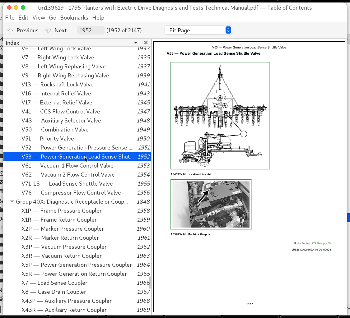
V53 — Power Generation Load Sense Shuttle Valve................1952
V61 — Vacuum 1 Flow Control Valve................1953
V62 — Vacuum 2 Flow Control Valve................1954
V71-LS — Load Sense Shuttle Valve................1955
V76 — Compressor Flow Control Valve................1956
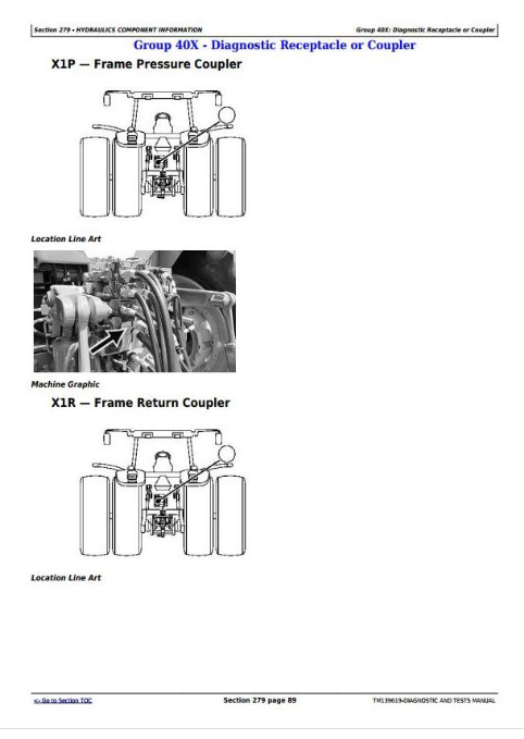
Group 40X: Diagnostic Receptacle or Coupler................1848
X1P — Frame Pressure Coupler................1958
X1R — Frame Return Coupler................1959
X2P — Marker Pressure Coupler................1960
X2R — Marker Return Coupler................1961
X3P — Vacuum Pressure Coupler................1962
X3R — Vacuum Return Coupler................1963
X5P — Power Generation Pressure Coupler................1964
X5R — Power Generation Return Coupler................1965
X7 — Load Sense Coupler................1966
X8 — Case Drain Coupler................1967
X43P — Auxiliary Pressure Coupler................1968
X43R — Auxiliary Return Coupler................1969
X75 — Compressor Diagnostic Receptacle................1970
Group 40Y: Solenoid Valve................1849
Y1 — Center Frame Solenoid Valve................1973
Y5 — Left Marker Solenoid Valve................1975
Y6 — Right Marker Solenoid Valve................1977
Y8 — Auxiliary Fold Solenoid Valve................1979
Y9 — Main Fold Solenoid Valve................1981
Y11 — Rockshaft Solenoid Valve 2................1983
Y15 — Rockshaft Solenoid Valve 1................1985
Y18 — Plant Solenoid Valve 1................1987
Y19 — Plant Solenoid Valve 2................1989
Y20 — Plant Solenoid Valve 3................1991
Y21 — Plant Solenoid Valve 4................1993
Y22 — Transport Solenoid Valve 1................1995
Y23 — Transport Solenoid Valve 2................1997
Y24 — Transport Solenoid Valve 3................1999
Y25 — Transport Solenoid Valve 4................2001
Y26 — Hitch-Marker Solenoid Valve 1................2003
Y27 — Hitch-Marker Solenoid Valve 2................2004
Y41 — CCS Blower Solenoid Valve................2005
Y51 — Alternator Motor Flow Solenoid Valve................2006
Y70 — Hydraulic Compressor Solenoid Valve................2007
Y501 - Y532 — Row Downforce Solenoid Valves................2008
Section 280: Pneumatics................2009
Group 20: Theory of Operation................2009
Closing Wheels Pneumatic Theory of Operation................2012
Downforce Pneumatic Theory of Operation................2014
Row Cleaners Pneumatic Theory of Operation................2015
Group 30: Schematics................2009
Closing Wheels Pneumatic Schematic................2021
Downforce Pneumatic Schematic................2025
Row Cleaners Pneumatic Schematic................2029
Group 50: Diagnostics................2009
Closing Wheels Pneumatic Diagnostic................2041
Downforce Pneumatic Diagnostic................2049
Row Cleaners Pneumatic Diagnostic................2057
Section 289: Pneumatics Component Information................2067
Group 40A: Accumulators................2067
A201-A232 — Row Air Springs................2071
A301-1 - A332-1 — Row Cleaner Air Springs Down................2072
A301-2 - A332-2 — Row Cleaner Air Springs Up................2074
A401 - A432 — Closing Wheel Air Springs................2076
Group 40B: Sensors................2067
B70-1 — Tank Pressure Sensor................2078
B70-2 — Tank Pressure Gauge................2079
B71 — Pressure Sensor 1................2080
B72 — Pressure Sensor 2................2081
B73 — Pressure Sensor 3................2082
B74 — Pressure Sensor 4................2083
B75 — Pressure Sensor 5................2084
B76 — Pressure Sensor 6................2085
B77 — Pressure Sensor 7................2086
Group 40D: Check Valves................2067
D70 — Compressor Outlet Check Valve................2088
Group 40F: Filters................2067
F70 — Compressor Inlet Filter................2090
Group 40G: Assembly Groups................2067
G70 — Compressor Assembly................2092
G71 — Pneumatic Manifold................2093
Group 40P: Pumps................2067
P70 — Compressor................2095
Group 40R: Reservoirs................2067
R70 — Air Tank................2097
Group 40V: Valves................2067
V70-1 — Tank Condensate Drain................2099
V70-2 — Tank Relief Valve................2100
V71-1 — Pressure Increase Valve 1................2101
V71-2 — Pressure Decrease Valve 1................2102
V71-3 — Relief Valve 1................2103
V71-4 — Fill Valve 1................2104
V72-1 — Pressure Increase Valve 2................2105
V72-2 — Pressure Decrease Valve 2................2106
V72-3 — Relief Valve 2................2107
V72-4 — Fill Valve 2................2108
V73-1 — Pressure Increase Valve 3................2109
V73-2 — Pressure Decrease Valve 3................2110
V73-3 — Relief Valve 3................2111
V73-4 — Fill Valve 3................2112
V74-1 — Pressure Increase Valve 4................2113
V74-2 — Pressure Decrease Valve 4................2114
V74-3 — Relief Valve 4................2115
V74-4 — Fill Valve 4................2116
V75-1 — Pressure Increase Valve 5................2117
V75-2 — Pressure Decrease Valve 5................2118
V75-3 — Relief Valve 5................2119
V75-4 — Fill Valve 5................2120
V76-1 — Pressure Increase Valve 6................2121
V76-2 — Pressure Decrease Valve 6................2122
V76-3 — Relief Valve 6................2123
V76-4 — Fill Valve 6................2124
V77-1 — Pressure Increase Valve 7................2125
V77-2 — Pressure Decrease Valve 7................2126
V77-3 — Relief Valve 7................2127
V77-4 — Fill Valve 7................2128
Group 40Y: Solenoid Valves................2068
Y71-1 — Fill Solenoid Valve 1................2130
Y71-2 — Exhaust Solenoid Valve 1................2131
Y72-1 — Fill Solenoid Valve 2................2132
Y72-2 — Exhaust Solenoid Valve 2................2133
Y73-1 — Fill Solenoid Valve 3................2134
Y73-2 — Exhaust Solenoid Valve 3................2135
Y74-1 — Fill Solenoid Valve 4................2136
Y74-2 — Exhaust Solenoid Valve 4................2137
Y75-1 — Fill Solenoid Valve 5................2138
Y75-2 — Exhaust Solenoid Valve 5................2139
Y76-1 — Fill Solenoid Valve 6................2140
Y76-2 — Exhaust Solenoid Valve 6................2141
Y77-1 — Fill Solenoid Valve 7................2142
Y77-2 — Exhaust Solenoid Valve 7................2143
John Deere Planters Models 1795 with ExactEmerge Row Units Diagnosis and Tests Service Technical Manual (TM139619)
![]()