
John Deere Planter with MaxEmerge 5 Row Units Models 1795 Diagnostic and Repair Service Manual (TM131719)
Complete All Inclusive Technical Manual with electrical wiring diagrams for John Deere Planter with MaxEmerge 5 Row Units Models 1795 (SN. from 760101), with all the workshop information to maintain, diagnose, repair, and rebuild like professional mechanics (Diagnosis, Operation, Tests, Repair, Service, Troubleshooting).
John Deere Planter with MaxEmerge 5 Row Units Models 1795 workshop technical service manual includes:
* Numbered table of contents easy to use so that you can find the information you need fast.
* Detailed sub-steps expand on repair procedure information
* Numbered instructions guide you through every repair procedure step by step.
* Troubleshooting and electrical service procedures are combined with detailed wiring diagrams for ease of use.
* Notes, cautions and warnings throughout each chapter pinpoint critical information.
* Bold figure number help you quickly match illustrations with instructions.
* Detailed illustrations, drawings and photos guide you through every procedure.
* Enlarged inset helps you identify and examine parts in detail.
tm131719 - 1795 Planterwith MaxEmerge 5 Row Units Diagnosis and Tests Technical Manual.pdf
tm131719 - 1795 Planterwith MaxEmerge 5 Row Units Diagnosis and Tests Technical Manual.epub
PRODUCT DETAILS:
Total Pages: 1,933 pages
File Format: PDF/EPUB/MOBI/AZW (PC/Mac/Android/Kindle/iPhone/iPad; bookmarked, ToC, Searchable, Printable)
Language: English
MAIN SECTIONS
Foreword
General Information
Acronym Table
How to Use This Manual
Safety
Lubricants
Recommended Tools for Diagnostics
Basic Diagnostics
Diagnostic Information for Electrical Components
Diagnostic Information for Hydraulic Components
Maintaining Hydraulic Systems and Components
Standard Torque Chart Procedures
Diagnostic Trouble Codes
Accessing Diagnostic Trouble Codes
Planter Main 1 (PM1) Codes
Planter Main 2 (PM2) Codes
Planter Auxiliary 1 (PA1) Codes
Observable Symptoms and System Diagnostics
Observable Symptoms
Electrical
General Information
Theory of Operation
Schematics - Frame
Schematics - CAN Bus
Schematics - Enhanced Monitoring
Schematics - Pneumatic Downforce
Schematics - Row Command
Schematics - Seed Monitoring
Diagnostics
Electronic Control Units
Accessing Diagnostic Addresses
Diagnostic Addresses by Control Unit
Diagnostics
Electrical Component Information
Electrical Assemblies
Sensors
Lights
Fuses
Charging
Relays
Motors
Switches
Diodes
Interconnects and Ground Points
Electrically Actuated Mechanical Devices
Hydraulics
Theory of Operation
Schematics
Diagnostics
Hydraulic Component Information
Cylinder, Actuator, or Piston
Check Valve
Filter
Valve Block, Assembly, or Gearcase
Cooler
Motor
Orifice
Reservoir Tank
Valve
Diagnostic Receptacle or Coupler
Solenoid Valve
Pneumatics
Theory of Operation
Schematics
Diagnostics
Pneumatic Components
Accumulators
Sensors
Check Valves
Filters
Assembly Groups
Pumps
Reservoirs
Switches
Valves
Couplers or Diagnostic Receptacles
Solenoid Valves
TABLE OF CONTENTS................1
Section 210: General Information................492
Group 10: Acronym Table................37
Acronym Table................37
Group 5A: How to Use This Manual................33
Information is Available in Sections, Groups and Subgroups................39
Group 5B: Safety................33
Work In Ventilated Area................41
Recognize Safety Information................42
Avoid Backover Accidents................43
Prevent Machine Runaway................44
Avoid Contact with Agricultural Chemicals................45
Clean Vehicle of Hazardous Pesticides................47
Use a Safety Chain................48
Work in Clean Area................49
Decommissioning — Proper Recycling and Disposal of Fluids and Components................50
Prepare for Emergencies................51
In Case of Fire................52
Use Safety Lights and Devices................53
Avoid High-Pressure Fluids................54
Use Proper Lifting Equipment................55
Illuminate Work Area Safely................56
Live With Safety................57
Support Machine Properly................58
Freeing a Mired Machine................59
Protect Against Noise................60
Remove Paint Before Welding or Heating................61
Park Machine Safely................62
Prevent Acid Burns................63
Follow Safety Instructions................65
Use Proper Tools................66
Keep Riders Off Machine................67
Service Tires Safely................68
Stay Clear of Rotating Drivelines................69
Construct Dealer-Made Tools Safely................70
Practice Safe Maintenance................71
Understand Signal Words................72
Replace Safety Signs................73
Prevent Battery Explosions................74
Protect Against High Pressure Spray................75
Avoid Heating Near Pressurized Fluid Lines................76
Tow Loads Safely................77
Transport Towed Equipment at Safe Speeds................78
Observe Maximum Transport Speed................80
Wear Protective Clothing................81
Precautions for Welding................82
Handle Agricultural Chemicals Safely................84
Service and Operate Chemical Sprayers Safely................86
Relieve Hydraulic Pressure Safely................88
Use Steps and Handholds Correctly................89
Group 5C: Lubricants................34
Grease................91
Gear Oil................92
Alternative and Synthetic Lubricants................93
Lubricant Storage................94
Group 5D: Recommended Tools for Diagnostics................34
Recommended Tools................97
Group 5E: Basic Diagnostics................34
Seven Basic Steps................101
Troubleshooting Unresolved Problems................103
Group 5F: Diagnostic Information for Electrical Components................34
Electrical Designators................105
Visually Inspect Electrical System................106
Group 5G: Diagnostic Information for Hydraulic Components................114
Hydraulic Designators................109
Troubleshooting Tips................110
Visually Inspect Hydraulic System................111
Group 5H: Maintaining Hydraulic Systems and Components................35
Hydraulic Components................114
Oil Storage and Filling................115
Oil Filtration................116
Group 5I: Standard Torque Chart Procedures................35
Unified Inch Bolt and Screw Torque Values................120
Metric Bolt and Screw Torque Values................123
Section 211: Diagnostic Trouble Codes................125
Group 10A: Accessing Diagnostic Trouble Codes................136
Accessing Diagnostic Trouble Codes................136
Group 10B: Closing Wheel Controller (CWC) Codes................125
CWC 001351.14 - Air Supply System................125
CWC 001387.00 - System control disabled................125
CWC 001387.01 - System control disabled................125
CWC 001387.03 - Closing Wheel Control System................125
CWC 001387.04 - Closing Wheel Control System................125
CWC 001387.10 - System control disabled................125
CWC 001387.13 - Closing Wheel Control System................125
CWC 001387.14 - Closing Wheel Control System................125
CWC 001387.16 - Pressure too high on Closing Wheel Group 1................125
CWC 001387.17 - Moderate leak detected on Closing Wheel Group 1................125
CWC 001388.00 - System control disabled................125
CWC 001388.01 - System control disabled................125
CWC 001388.03 - Closing Wheel Control System................125
CWC 001388.04 - Closing Wheel Control System................125
CWC 001388.10 - System control disabled................125
CWC 001388.13 - Closing Wheel Control System................125
CWC 001388.14 - Closing Wheel Control System................125
CWC 001388.16 - Pressure too high on Closing Wheel Group 2................125
CWC 001388.17 - Moderate leak detected on Closing Wheel Group 2................125
CWC 003509.03 - Sensor Voltage is above Normal................125
CWC 003509.04 - Sensor Voltage is below Normal................125
CWC 517151.01 - Closing Wheel Control System................125
CWC 517151.03 - Closing Wheel Control System................125
CWC 517151.04 - Closing Wheel Control System................125
CWC 517151.05 - Closing Wheel Control System................125
CWC 517151.06 - Closing Wheel Control System................125
CWC 517151.12 - Closing Wheel Control System................125
CWC 517152.03 - Closing Wheel Control System................125
CWC 517152.04 - Closing Wheel Control System................125
CWC 517152.12 - Closing Wheel Control System................126
CWC 517153.01 - Closing Wheel Control System................126
CWC 517153.03 - Closing Wheel Control System................126
CWC 517153.04 - Closing Wheel Control System................126
CWC 517153.05 - Closing Wheel Control System................126
CWC 517153.06 - Closing Wheel Control System................126
CWC 517153.12 - Closing Wheel Control System................126
CWC 517154.03 - Closing Wheel Control System................126
CWC 517154.04 - Closing Wheel Control System................126
CWC 517154.12 - Closing Wheel Control System................126
CWC 517154.31 - Closing Wheel Control System................126
520463.03 - Closing Wheel Control ECU Power................126
520463.04 - Closing Wheel Control ECU Power................126
523218.03 - Valve Power 2 Voltage Above Normal................126
523218.04 - Closing Wheel Control Valve Power 2................126
523218.05 - Closing Wheel Control Valve Power 2................126
CWC 523438.02 - EEPROM Checksum Error................126
CWC 523438.14 - EEPROM Out of Bounds Error................126
Group 10C: Planter Main 1 (PM1) Codes................126
PM1 000084.09 - Wheel Speed Not Detected On CAN Bus................126
PM1 000609.12 - Planter Module 2 Not Responding................126
PM1 000629.14 - Planter Disabled, Cycle Power................126
PM1 001859.09 - Radar Speed Not Detected On CAN Bus................126
PM1 001859.10 - Ground Speed and Tractor Speed Conflict................126
PM1 001859.14 - Minimum Speed Not Reached At End Of QuickStart................126
PM1 003132.00 - Fertilizer Pressure 1 High................126
PM1 003132.03 - Fertilizer Sensor 1 Voltage High................126
PM1 003132.04 - Fertilizer Sensor 1 Voltage Low................126
PM1 003509.03 - 5 Volt Sensor Supply Voltage High................126
PM1 003509.04 - 5 Volt Sensor Supply Voltage Low................126
PM1 003510.03 - 8 Volt Sensor Supply Voltage High................126
PM1 003510.04 - 8 Volt Sensor Supply Voltage Low................126
PM1 005109.12 - Planter Module 3 Not Responding................126
PM1 005117.01 - EPM 1 Input Voltage Low................127
PM1 005117.02 - EPM 1 Not Responding To Setup................127
PM1 005117.12 - EPM 1 Offline................127
PM1 005117.18 - EPM 1 Low Voltage On Inputs................127
PM1 005118.01 - EPM 2 Input Voltage Low................127
PM1 005118.02 - EPM 2 Not Responding To Setup................127
PM1 005118.12 - EPM 2 Offline................127
PM1 005118.18 - EPM 2 Low Voltage On Inputs................127
PM1 005119.01 - EPM 3 Input Voltage Low................127
PM1 005119.02 - EPM 3 Not Responding To Setup................127
PM1 005119.12 - EPM 3 Offline................127
PM1 005119.18 - EPM 3 Low Voltage On Inputs................127
PM1 005120.01 - EPM 4 Input Voltage Low................127
PM1 005120.02 - EPM 4 Not Responding To Setup................127
PM1 005120.14 - EPM 4 Offline................127
PM1 005120.18 - EPM 4 Low Voltage On Inputs................127
PM1 520328.02 - Seed Detected On Row 1 While Deactivated................127
PM1 520328.12 - Row 1 Clutch Failed................127
PM1 521037.03 - Vacuum 1 Sensor Voltage High................127
PM1 521037.04 - Vacuum 1 Sensor Voltage Low................127
PM1 521037.17 - Vacuum 1 Pressure Low................127
PM1 521124.03 - Vacuum 2 Sensor Voltage High................127
PM1 521124.04 - Vacuum 2 Sensor Voltage Low................127
PM1 521124.17 - Vacuum 2 Pressure Low................127
PM1 521633.07 - VRD 1 Frequency Low................127
PM1 521633.10 - VRD 1 Frequency Abnormal................127
PM1 521726.07 - VRD 2 Frequency Low................127
PM1 521726.10 - VRD 2 Frequency Abnormal................127
PM1 522260.02 - Motion Sensor Speed and Tractor Speed Conflict................127
PM1 522260.10 - Motion Sensor Responding When No Active Tractor Speed................127
PM1 522317.02 - Seed Detected On Row 32 While Deactivated................127
PM1 522317.12 - Row 32 Clutch Failed................127
PM1 522318.02 - Seed Detected On Row 31 While Deactivated................127
PM1 522318.12 - Row 31 Clutch Failed................128
PM1 522319.02 - Seed Detected On Row 30 While Deactivated................128
PM1 522319.12 - Row 30 Clutch Failed................128
PM1 522321.02 - Seed Detected On Row 29 While Deactivated................128
PM1 522321.12 - Row 29 Clutch Failed................128
PM1 522322.02 - Seed Detected On Row 28 While Deactivated................128
PM1 522322.12 - Row 28 Clutch Failed................128
PM1 522323.02 - Seed Detected On Row 27 While Deactivated................128
PM1 522323.12 - Row 27 Clutch Failed................128
PM1 522324.02 - Seed Detected On Row 26 While Deactivated................128
PM1 522324.12 - Row 26 Clutch Failed................128
PM1 522325.02 - Seed Detected On Row 25 While Deactivated................128
PM1 522325.12 - Row 25 Clutch Failed................128
PM1 522328.02 - Seed Detected On Row 24 While Deactivated................128
PM1 522328.12 - Row 24 Clutch Failed................128
PM1 522329.02 - Seed Detected On Row 23 While Deactivated................128
PM1 522329.12 - Row 23 Clutch Failed................128
PM1 522330.02 - Seed Detected On Row 22 While Deactivated................128
PM1 522330.12 - Row 22 Clutch Failed................128
PM1 522331.02 - Seed Detected On Row 21 While Deactivated................128
PM1 522331.12 - Row 21 Clutch Failed................128
PM1 522332.02 - Seed Detected On Row 20 While Deactivated................128
PM1 522332.12 - Row 20 Clutch Failed................128
PM1 522333.02 - Seed Detected On Row 19 While Deactivated................128
PM1 522333.12 - Row 19 Clutch Failed................128
PM1 522334.02 - Seed Detected On Row 18 While Deactivated................128
PM1 522334.12 - Row 18 Clutch Failed................128
PM1 522335.02 - Seed Detected On Row 17 While Deactivated................128
PM1 522335.12 - Row 17 Clutch Failed................128
PM1 522336.02 - Seed Detected On Row 16 While Deactivated................128
PM1 522336.12 - Row 16 Clutch Failed................128
PM1 522337.02 - Seed Detected On Row 15 While Deactivated................128
PM1 522337.12 - Row 15 Clutch Failed................128
PM1 522338.02 - Seed Detected On Row 14 While Deactivated................129
PM1 522338.12 - Row 14 Clutch Failed................129
PM1 522339.02 - Seed Detected On Row 13 While Deactivated................129
PM1 522339.12 - Row 13 Clutch Failed................129
PM1 522342.02 - Seed Detected On Row 12 While Deactivated................129
PM1 522342.12 - Row 12 Clutch Failed................129
PM1 522346.02 - Seed Detected On Row 11 While Deactivated................129
PM1 522346.12 - Row 11 Clutch Failed................129
PM1 522347.02 - Seed Detected On Row 10 While Deactivated................129
PM1 522347.12 - Row 10 Clutch Failed................129
PM1 522348.02 - Seed Detected On Row 9 While Deactivated................129
PM1 522348.12 - Row 9 Clutch Failed................129
PM1 522349.02 - Seed Detected On Row 8 While Deactivated................129
PM1 522349.12 - Row 8 Clutch Failed................129
PM1 522351.02 - Seed Detected On Row 7 While Deactivated................129
PM1 522351.12 - Row 7 Clutch Failed................129
PM1 522352.02 - Seed Detected On Row 6 While Deactivated................129
PM1 522352.12 - Row 6 Clutch Failed................129
PM1 522353.02 - Seed Detected On Row 5 While Deactivated................129
PM1 522353.12 - Row 5 Clutch Failed................129
PM1 522354.02 - Seed Detected On Row 4 While Deactivated................129
PM1 522354.12 - Row 4 Clutch Failed................129
PM1 522355.02 - Seed Detected On Row 3 While Deactivated................129
PM1 522355.12 - Row 3 Clutch Failed................129
PM1 522356.02 - Seed Detected On Row 2 While Deactivated................129
PM1 522356.12 - Row 2 Clutch Failed................129
PM1 522941.11 - Selected Ground Speed Source is Wheel................129
PM1 522941.14 - Selected Ground Speed Source is Manual................129
PM1 522942.09 - Planting Parameters Satisfied Before Controller Initialized................129
PM1 523111.14 - Reset System Parameters................129
PM1 523161.31 - Row 24 Seed Sensor Not Responding................129
PM1 523163.31 - Row 23 Seed Sensor Not Responding................129
PM1 523164.31 - Row 22 Seed Sensor Not Responding................129
PM1 523165.31 - Row 21 Seed Sensor Not Responding................130
PM1 523166.31 - Row 20 Seed Sensor Not Responding................130
PM1 523167.31 - Row 19 Seed Sensor Not Responding................130
PM1 523168.31 - Row 18 Seed Sensor Not Responding................130
PM1 523169.31 - Row 17 Seed Sensor Not Responding................130
PM1 523170.31 - Row 16 Seed Sensor Not Responding................130
PM1 523171.31 - Row 15 Seed Sensor Not Responding................130
PM1 523172.31 - Row 14 Seed Sensor Not Responding................130
PM1 523173.31 - Row 13 Seed Sensor Not Responding................130
PM1 523174.31 - Row 12 Seed Sensor Not Responding................130
PM1 523175.31 - Row 11 Seed Sensor Not Responding................130
PM1 523176.31 - Row 10 Seed Sensor Not Responding................130
PM1 523177.31 - Row 9 Seed Sensor Not Responding................130
PM1 523178.31 - Row 8 Seed Sensor Not Responding................130
PM1 523179.31 - Row 7 Seed Sensor Not Responding................130
PM1 523180.31 - Row 6 Seed Sensor Not Responding................130
PM1 523181.31 - Row 5 Seed Sensor Not Responding................130
PM1 523182.31 - Row 4 Seed Sensor Not Responding................130
PM1 523183.31 - Row 3 Seed Sensor Not Responding................130
PM1 523184.31 - Row 2 Seed Sensor Not Responding................130
PM1 523185.31 - Row 1 Seed Sensor Not Responding................130
PM1 523194.31 - Rows Not Planting................130
PM1 523319.03 - ECU Power Voltage High................130
PM1 523319.04 - ECU Power Voltage Low................130
PM1 523328.11 - Height Sensor Not Calibrated................130
PM1 523328.14 - Height Sensor Below Normal Operating Range................130
PM1 523436.31 - Watchdog Reset For Seed Monitor................130
PM1 523651.11 - Internal Stack Overflow................130
PM1 523652.03 - High Current Power Voltage High................130
PM1 523652.04 - High Current Power Voltage Low................130
PM1 523705.31 - Watchdog Reset For Seed Monitor And VRD................130
PM1 523773.03 - CAN High Voltage High................130
PM1 523773.04 - CAN High Voltage Low................130
PM1 523774.03 - CAN Low Voltage High................131
PM1 523774.04 - CAN Low Voltage Low................131
PM1 524054.14 - Specified Area Has Been Planted................131
PM1 524055.11 - Stored NOVRAM Value Abnormal................131
Group 10D: Planter Main 2 (PM2) Codes................131
PM2 000609.02 - Seed Monitor Not Responding................131
PM2 000609.12 - Seed Monitor Offline................131
PM2 000629.12 - Watchdog Timed Out................131
PM2 000639.12 - Implement CAN Bus Lost Message................131
PM2 000639.14 - Implement CAN Bus Excessive Errors................131
PM2 000705.13 - Node 1 Sensor Calibration Error................131
PM2 000705.19 - Node 1 Downforce Sensor Error................131
PM2 000706.13 - Node 2 Sensor Calibration Error................131
PM2 000706.19 - Node 2 Downforce Sensor Error................131
PM2 000707.13 - Node 3 Sensor Calibration Error................131
PM2 000707.19 - Node 3 Downforce Sensor Error................131
PM2 000708.13 - Node 4 Sensor Calibration Error................131
PM2 000708.19 - Node 4 Downforce Sensor Error................131
PM2 000709.13 - Node 5 Sensor Calibration Error................131
PM2 000709.19 - Node 5 Downforce Sensor Error................131
PM2 001231.12 - Left CAN Bus Lost Message................131
PM2 001231.14 - Left CAN Bus Excessive Errors................131
PM2 001235.12 - Right CAN Bus Lost Message................131
PM2 001235.14 - Right CAN Bus Excessive Errors................131
PM2 001351.14 - Compressor Motor Time Limit Exceeded................131
PM2 003509.03 - 5 Volt Sensor Supply Voltage High................131
PM2 003509.04 - 5 Volt Sensor Supply Voltage Low................131
PM2 005111.02 - Node 1 Message Missing................131
PM2 005111.12 - Node 1 Missing................131
PM2 005111.19 - Node 1 Accelerometer Fault................131
PM2 005112.02 - Node 2 Message Missing................131
PM2 005112.12 - Node 2 Missing................131
PM2 005112.19 - Node 2 Accelerometer Fault................131
PM2 005113.02 - Node 3 Message Missing................132
PM2 005113.12 - Node 3 Missing................132
PM2 005113.19 - Node 3 Accelerometer Fault................132
PM2 005114.02 - Node 4 Message Missing................132
PM2 005114.12 - Node 4 Missing................132
PM2 005114.19 - Node 4 Accelerometer Fault................132
PM2 005115.02 - Node 5 Message Missing................132
PM2 005115.12 - Node 5 Missing................132
PM2 005115.19 - Node 5 Accelerometer Fault................132
PM2 521087.03 - Increase Solenoid Feedback Voltage High................132
PM2 521087.05 - Increase Solenoid Current Low................132
PM2 521087.06 - Increase Solenoid Current High................132
PM2 521092.03 - Exhaust Solenoid Feedback Voltage High................132
PM2 521092.05 - Exhaust Solenoid Current Low................132
PM2 521092.06 - Exhaust Solenoid Current High................132
PM2 521130.03 - Row Unit Downforce Sensor Signal Voltage High................132
PM2 521130.06 - Row Unit Downforce Sensor Signal Voltage Low................132
PM2 521130.13 - Row Unit Downforce Sensor Zero Error................132
PM2 521938.03 - Right Address Feedback Voltage High................132
PM2 521938.05 - Right Address Line Open................132
PM2 521938.06 - Right Address Current High................132
PM2 521939.03 - Row Unit Downforce Sensor Signal Voltage High................132
PM2 521939.06 - Row Unit Downforce Sensor Signal Voltage Low................132
PM2 521939.13 - Row Unit Downforce Sensor Zero Error................132
PM2 521940.03 - Exhaust Solenoid Feedback Voltage High................132
PM2 521940.05 - Exhaust Solenoid Current Low................132
PM2 521940.06 - Exhaust Solenoid Current High................132
PM2 521941.03 - Increase Solenoid Feedback Voltage High................132
PM2 521941.05 - Increase Solenoid Current Low................132
PM2 521941.06 - Increase Solenoid Current High................132
PM2 523219.03 - High Current Power Voltage High................132
PM2 523219.04 - High Current Power Voltage Low................132
PM2 523219.05 - High Current Power Not Detected................132
PM2 523319.03 - ECU Power Voltage High................133
PM2 523319.04 - ECU Power Voltage Low................133
PM2 523685.03 - Left Address Feedback Voltage High................133
PM2 523685.05 - Left Address Line Open................133
PM2 523685.06 - Left Address Current High................133
Group 10E: Planter Auxiliary 1 (PA1) Codes................133
PA1 003510.03 - 8 Volt Sensor Supply Voltage High................133
PA1 003510.04 - 8 Volt Sensor Supply Voltage Low................133
PA1 523178.31 - Row 32 Seed Sensor Not Responding................133
PA1 523179.31 - Row 31 Seed Sensor Not Responding................133
PA1 523180.31 - Row 30 Seed Sensor Not Responding................133
PA1 523181.31 - Row 29 Seed Sensor Not Responding................133
PA1 523182.31 - Row 28 Seed Sensor Not Responding................133
PA1 523183.31 - Row 27 Seed Sensor Not Responding................133
PA1 523184.31 - Row 26 Seed Sensor Not Responding................133
PA1 523185.31 - Row Seed 25 Seed Sensor Not Responding................133
PA1 523194.31 - Rows Not Planting................133
PA1 523319.03 - ECU Power Voltage High................133
PA1 523319.04 - ECU Power Voltage Low................133
PA1 523436.31 - Watchdog Reset For Seed Monitor................133
PA1 523651.11 - Internal Stack Overflow................133
PA1 523773.03 - CAN High Voltage High................133
PA1 523773.04 - CAN High Voltage Low................133
PA1 523774.03 - CAN Low Voltage High................133
PA1 523774.04 - CAN Low Voltage Low................133
Section 212: Observable Symptoms and System Diagnostics................424
Group 10: Observable Symptoms................424
Auxiliary Hydraulics Observable Symptoms................427
Auxiliary Power Observable Symptoms................428
CAN Bus Observable Symptoms................429
CCS Agitator Observable Symptoms................431
CCS Blower Observable Symptoms................432
CCS Tank Low Warning Observable Symptoms................434
Drawbar Hitch Observable Symptoms................435
Electronic Control Unit (ECU) Power and Ground Observable Symptoms................436
Enhanced Monitoring Observable Symptoms................437
Fertilizer Pressure Observable Symptoms................438
Field Lift Observable Symptoms................439
Fold Observable Symptoms................441
Frame Control Console Observable Symptoms................443
Ground Drive Disconnects Observable Symptoms................444
Height Sensor Observable Symptoms................445
High Current Power and Ground Observable Symptoms................446
Implement Receiver Observable Symptoms................447
Insecticide Disconnects Observable Symptoms................448
Lighting - CCS Fill Lights Observable Symptoms................449
Lighting - Transport Lights Observable Symptoms................451
Markers Observable Symptoms................453
Pneumatic Closing Wheels Observable Symptoms................454
Pneumatic Downforce Observable Symptoms................456
Population Observable Symptoms................459
Rate Controller Observable Symptoms................461
Rockshafts Observable Symptoms................463
Row Command Observable Symptoms................465
Seed Monitoring Observable Symptoms................467
SeedStar Mobile Observable Symptoms................469
Transport Lift Observable Symptoms................471
Vacuum Observable Symptoms................473
Variable Rate Drive Observable Symptoms................474
Variable Rate Fertilizer Observable Symptoms................477
Section 240: Electrical................478
Group 05: General Information................492
General Information................492
Intermittent Fault Diagnostics................502
Solenoid Sequence Table................503
Circuit Load Test................504
Group 20: Theory of Operation................478
Auxiliary Hydraulics Electrical Theory of Operation................508
Auxiliary Power Electrical Theory of Operation................509
CAN Bus Electrical Theory of Operation................510
CCS Agitator Electrical Theory of Operation................511
CCS Blower Electrical Theory of Operation................512
CCS Tank Low Warning Electrical Theory of Operation................513
Drawbar Hitch Electrical Theory of Operation................514
Electronic Control Unit (ECU) Power and Ground Electrical Theory of Operation................515
Enhanced Monitoring Electrical Theory of Operation................516
Fertilizer Pressure Electrical Theory of Operation................517
Field Lift Electrical Theory of Operation................518
Fold Electrical Theory of Operation................519
Frame Control Console Electrical Theory of Operation................520
Ground Drive Disconnects Electrical Theory of Operation................522
Height Sensor Electrical Theory of Operation................523
High Current Power and Ground Electrical Theory of Operation................524
Implement Receiver Electrical Theory of Operation................525
Insecticide Disconnects Electrical Theory of Operation................526
Lighting - CCS Fill Lights Electrical Theory of Operation................527
Lighting - Transport Lights (EU) Electrical Theory of Operation................528
Lighting - Transport Lights (NA) Electrical Theory of Operation................529
Markers Electrical Theory of Operation................531
Pneumatic Closing Wheels Electrical Theory of Operation................533
Pneumatic Downforce Electrical Theory of Operation................535
Rate Controller Electrical Theory of Operation................538
Rockshafts Electrical Theory of Operation................539
Row Command Electrical Theory of Operation................540
Seed Monitoring Electrical Theory of Operation................541
SeedStar Mobile Electrical Theory of Operation................542
Transport Lift Electrical Theory of Operation................544
Vacuum Electrical Theory of Operation................545
Variable Rate Drive Electrical Theory of Operation................546
Variable Rate Fertilizer Electrical Theory of Operation................547
Group 30A: Schematics - Frame................479
Auxiliary Hydraulics Electrical Schematic................553
Auxiliary Power Electrical Schematic................557
CCS Agitator Electrical Schematic................558
CCS Blower Electrical Schematic................562
CCS Tank Low Warning Electrical Schematic................566
Drawbar Hitch Electrical Schematic................568
Electronic Control Unit (ECU) Power and Ground Electrical Schematic................570
Fertilizer Pressure Electrical Schematic................575
Field Lift Electrical Schematic................577
Fold Electrical Schematic................579
Frame Control Console Electrical Schematic................581
Ground Drive Disconnects Electrical Schematic................583
Height Sensor Electrical Schematic................586
High Current Power and Ground Electrical Schematic................587
Implement Receiver Electrical Schematic................592
Insecticide Disconnects Electrical Schematic................593
Lighting - CCS Fill Lights Electrical Schematic................596
Lighting - Transport Lights Identification................599
Lighting - Transport Lights (EU) Electrical Schematic................600
Lighting - Transport Lights (NA) Electrical Schematic................602
Markers Electrical Schematic................604
Pneumatic Closing Wheels Electrical Schematic................606
Rate Controller Electrical Schematic................609
Rockshafts Electrical Schematic................612
SeedStar Mobile Electrical Schematic................614
Transport Lift Electrical Schematic................616
Vacuum Electrical Schematic................618
Variable Rate Drive Electrical Schematic................620
Variable Rate Fertilizer Electrical Schematic................623
Group 30B: Schematics - CAN Bus................480
Implement CAN Bus Electrical Schematic................626
CAN Bus Electrical Schematic - Type Identification................628
CAN Bus Electrical Schematic - Type A................629
CAN Bus Electrical Schematic - Type B................631
Group 30C: Schematics - Enhanced Monitoring................480
Enhanced Monitoring Electrical Schematic - Type Identification................634
Enhanced Monitoring Electrical Schematic - Type A................635
Enhanced Monitoring Electrical Schematic - Type B................638
Group 30D: Schematics - Pneumatic Downforce................480
Pneumatic Downforce Electrical Schematic - Type Identification................642
Pneumatic Downforce Electrical Schematic - Type A................643
Pneumatic Downforce Electrical Schematic - Type B................646
Group 30E: Schematics - Row Command................480
Row Command Electrical Schematic - Type Identification................650
Row Command Electrical Schematic - Type A................651
Row Command Electrical Schematic - Type B................656
Row Command Electrical Schematic - Type C................661
Row Command Electrical Schematic - Type D................665
Row Command Electrical Schematic - Type E................671
Group 30F: Schematics - Seed Monitoring................480
Seed Monitoring Electrical Schematic - Type Identification................678
Seed Monitoring Electrical Schematic - Type A................679
Seed Monitoring Electrical Schematic - Type B................683
Seed Monitoring Electrical Schematic - Type C................687
Seed Monitoring Electrical Schematic - Type D................690
Seed Monitoring Electrical Schematic - Type E................694
Group 50: Diagnostics................480
Auxiliary Hydraulics Electrical Diagnostic................700
Auxiliary Power Electrical Diagnostic................702
CAN Bus Electrical Diagnostic................706
CCS Agitator Electrical Diagnostic................720
CCS Blower Electrical Diagnostic................726
CCS Tank Low Warning Electrical Diagnostic................732
Disconnects Electrical Diagnostic................736
Electric Compressor Diagnostic................744
Electronic Control Unit (ECU) Power and Ground Electrical Diagnostic................754
Enhanced Monitoring Electrical Diagnostic................770
Fertilizer Pressure Electrical Diagnostic................782
Field Lift Electrical Diagnostic................785
Fold Electrical Diagnostic................795
Frame Control Console Electrical Diagnostic................804
Height Sensor Electrical Diagnostic................823
High Current Power and Ground Electrical Diagnostic................827
Implement Receiver Electrical Diagnostic................835
Lighting - Transport Lights (EU) Electrical Diagnostic................841
Lighting - Transport Lights (NA) Electrical Diagnostic................849
Markers Electrical Diagnostic................862
Pneumatic Closing Wheels Electrical Diagnostic................874
Pneumatic Downforce Electrical Diagnostic................884
Rate Controller Electrical Diagnostic................896
Rockshafts Electrical Diagnostic................907
Row Command Electrical Diagnostic................912
Seed Monitoring Electrical Diagnostic................917
SeedStar Mobile Electrical Diagnostic................926
Transport Lift Electrical Diagnostic................940
Vacuum Electrical Diagnostic................950
Variable Rate Drive Electrical Diagnostic................954
Variable Rate Fertilizer Electrical Diagnostic................962
Section 245: Electronic Control Units................971
Group 10A: Accessing Diagnostic Addresses................974
Accessing Diagnostic Addresses................974
Group 10B: Diagnostic Addresses by Control Unit................971
Planter Auxiliary 1 (PA1) Addresses................978
Planter Main 1 (PM1) Addresses................980
Planter Main 2 (PM2) Addresses................988
Group 50: Diagnostics................971
Closing Wheel Controller (CWC) Test................998
Electronic Power Module (EPM) 1 Diagnostic Test................1002
Electronic Power Module (EPM) 2 Diagnostic Test................1008
Electronic Power Module (EPM) 3 Diagnostic Test................1013
Electronic Power Module (EPM) 4 Diagnostic Test................1018
Planter Auxiliary 1 (PA1) Control Unit Test................1023
Planter Main 1 (PM1) Control Unit Test................1027
Planter Main 2 (PM2) Control Unit Test................1032
Variable Rate Fertilizer (VRF) Control Unit Test................1037
Wireless Data Server (WDS) Test................1043
Section 249: Electrical Component Information................1050
Group 40A: Electrical Assemblies................1050
XA4 — Flasher Module Connector................1060
XA7 — Frame Control Console Connector................1062
XA8-1 — Rate Controller J1 Connector................1064
XA8-2 — Rate Controller J2 Connector................1067
XA8-3 — Rate Controller J3 Connector................1071
XA9 — Implement Receiver Connector................1074
XA10 — Implement CAN Bus Secondary Terminator Connector................1076
XA11-A — Planter Main 1 (PM1) Control Unit A1 Connector................1078
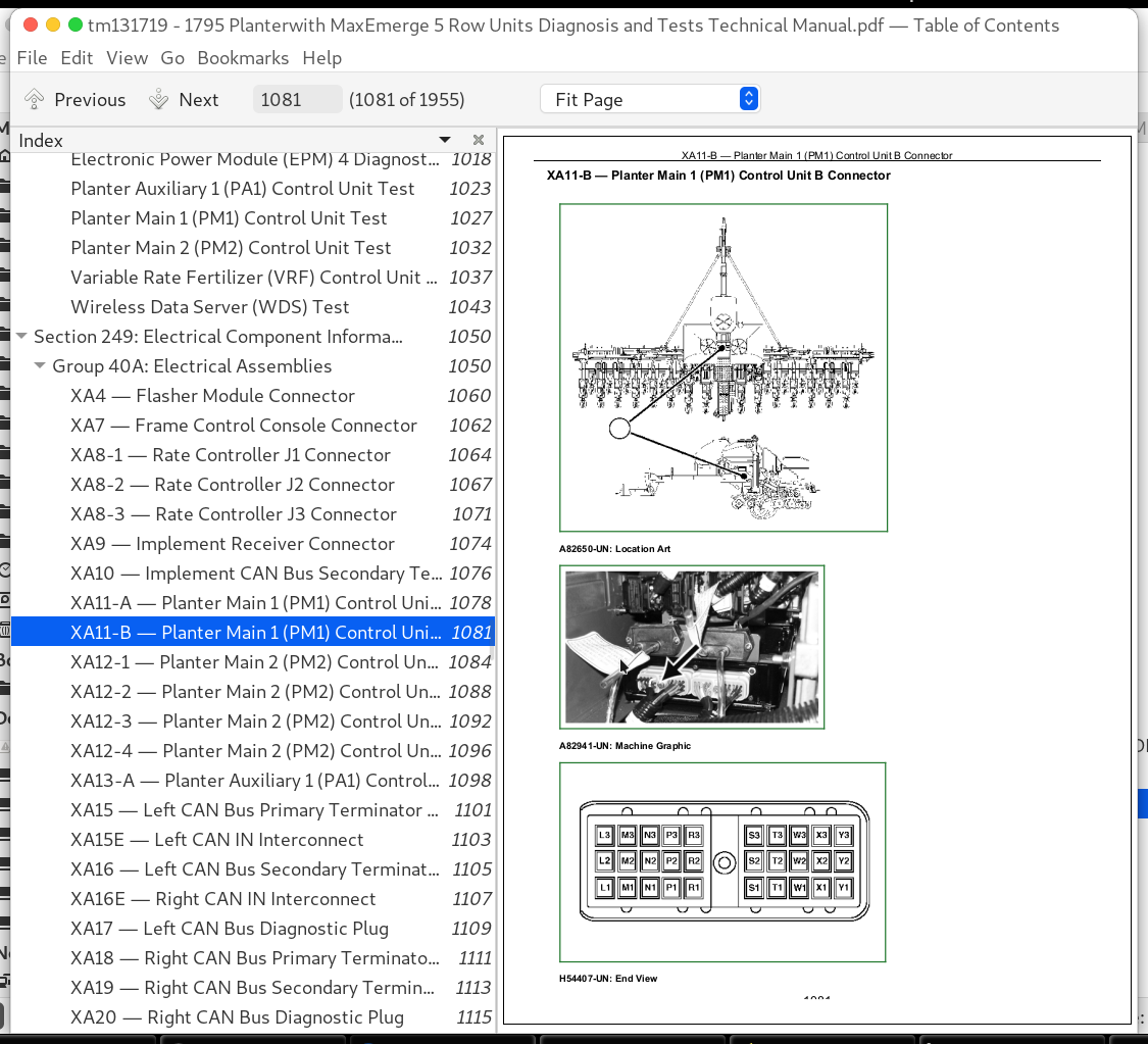
XA11-B — Planter Main 1 (PM1) Control Unit B Connector................1081
XA12-1 — Planter Main 2 (PM2) Control Unit J1 Connector................1084
XA12-2 — Planter Main 2 (PM2) Control Unit J2 Connector................1088
XA12-3 — Planter Main 2 (PM2) Control Unit J3 Connector................1092
XA12-4 — Planter Main 2 (PM2) Control Unit MMC Power Connector................1096
XA13-A — Planter Auxiliary 1 (PA1) Control Unit A2 Connector................1098
XA15 — Left CAN Bus Primary Terminator Connector................1101
XA15E — Left CAN IN Interconnect................1103
XA16 — Left CAN Bus Secondary Terminator Connector................1105
XA16E — Right CAN IN Interconnect................1107
XA17 — Left CAN Bus Diagnostic Plug................1109
XA18 — Right CAN Bus Primary Terminator Connector................1111
XA19 — Right CAN Bus Secondary Terminator Connector................1113
XA20 — Right CAN Bus Diagnostic Plug................1115
XA21-1 — EPM 1 - J1 Connector................1117
XA21-2 — EPM 1 - J2 Connector................1119
XA21-3 — EPM 1 - J3 Connector................1121
XA22-1 — EPM 2 - J1 Connector................1123
XA22-2 — EPM 2 - J2 Connector................1125
XA22-3 — EPM 2 - J3 Connector................1127
XA23-1 — EPM 3 - J1 Connector................1129
XA23-2 — EPM 3 - J2 Connector................1131
XA23-3 — EPM 3 - J3 Connector................1133
XA24-1 — EPM 4 - J1 Connector................1135
XA24-2 — EPM 4 - J2 Connector................1137
XA24-3 — EPM 4 - J3 Connector................1139
XA31 — Node 1 Connector................1141
XA32 — Node 2 Connector................1144
XA33 — Node 3 Connector................1147
XA34 — Node 4 Connector................1150
XA35 — Node 5 Connector................1153
XA70-1 — Closing Wheel Controller J1 Connector................1156
XA70-2 — Closing Wheel Controller J2 Connector................1160
XA80-1 — Variable Rate Fertilizer 30-pin Connector................1164
XA80-2 — Variable Rate Fertilizer 18-pin Connector................1167
XA90 — Wireless Data Server (WDS) Connector................1169
XA91-1 — Seed Controller 1 J1 Connector................1171
XA91-2 — Seed Controller 1 J2 Connector................1174
XA91-3 — Seed Controller 1 J3 Connector................1178
XA92-1 — Seed Controller 2 J1 Connector................1181
XA92-2 — Seed Controller 2 J2 Connector................1184
XA92-3 — Seed Controller 2 J3 Connector................1188
XA95-A — Junction Box 1 A Connector................1191
XA95-B — Junction Box 1 B Connector................1194
XA96-A — Junction Box 2 A Connector................1197
Group 40B: Sensors................1051
XB1 — Height Sensor Connector................1202
XB2 — Motion Sensor Connector................1204
XB31 — Gauge Wheel Load Sensor 1 Connector................1206
XB32 — Gauge Wheel Load Sensor 2 Connector................1209
XB33 — Gauge Wheel Load Sensor 3 Connector................1212
XB34 — Gauge Wheel Load Sensor 4 Connector................1215
XB35 — Gauge Wheel Load Sensor 5 Connector................1218
XB43 — Left Bin Level Sensor Connector................1221
XB44 — Right Bin Level Sensor Connector................1223
XB45 — Front Bin Level Sensor Connector................1225
XB51 — VRD 1 Speed Sensor Connector................1227
XB52 — VRD 2 Speed Sensor Connector................1229
XB61 — Vacuum 1 Pressure Sensor Connector................1231
XB62 — Vacuum 2 Pressure Sensor Connector................1233
XB71 — Air Spring Pressure Sensor 1 Connector................1235
XB72 — Air Spring Pressure Sensor 2 Connector................1238
XB76 — Pressure Sensor 6 Connector................1241
XB77 — Pressure Sensor 7 Connector................1243
XB81 — Fertilizer Pressure Sensor Connector................1245
XB81P — Fertilizer Pump Position Sensor Connector................1247
XB81S — Fertilizer Pump Speed Sensor Connector................1249
XB101-XB132 — Seed Sensor Connectors................1251
Group 40E: Lights................1052
XE1 — Left Amber Light (NA) Connector................1255
XE2 — Left Red Light (NA) Connector................1257
XE3 — Right Red Light (NA) Connector................1259
XE4 — Right Amber Light (NA) Connector................1261
XE11 — Left Amber Light (EU) Connector................1263
XE12 — Left Red Light (EU) Connector................1265
XE13 — Right Red Light (EU) Connector................1267
XE14 — Right Amber Light (EU) Connector................1269
XE43 — Left Fill Light Connector................1271
XE44 — Right Fill Light Connector................1273
XE45 — Front Fill Light Connector................1275
Group 40F: Fuses................1052
XF5 — Battery Adapter Fuse Connector................1279
XF7 — Frame Control Fuse Connector................1281
XF21 — EPM 1 Fuse Connector................1283
XF22 — EPM 2 Fuse Connector................1285
XF23 — EPM 3 Fuse Connector................1287
XF24 — EPM 4 Fuse Connector................1289
Group 40G: Charging................1052
XG8-N — Tractor Battery Negative Connector................1293
XG8-P — Tractor Battery Positive Connector................1295
Group 40K: Relays................1053
XK8 — Battery Adapter Relay Connector................1299
XK31 — Agitator Relay Connector................1301
XK34 — Transport Relay Connector................1303
XK35 — Plant Relay Connector................1305
XK70 — Electric Compressor Relay Connector................1307
Group 40M: Motors................1053
XM43-1 — Left Agitator Motor Power Connector................1311
XM43-2 — Left Agitator Motor Ground Connector................1313
XM44-1 — Right Agitator Motor Power Connector................1315
XM44-2 — Right Agitator Motor Ground Connector................1317
XM45-1 — Front Agitator Motor Power Connector................1319
XM45-2 — Front Agitator Motor Ground Connector................1321
XM70 — Electric Compressor Motor Connector................1323
Group 40S: Switches................1053
XS4 — Anti-Fold Switch Connector................1327
XS6 — Rockshaft Switch Connector................1329
XS7 — Auto Marker Switch Connector................1331
XS10 — Foot Switch Connector................1333
XS11 — Master Switch Connector................1335
XS17 — Row Switch Connector................1337
XS21 — Fold Switch 1 Connector................1339
XS22 — Fold Switch 2 Connector................1341
XS23 — Fold Switch 3 Connector................1343
XS26H — Hitch Control Hitch Connector................1345
XS26M — Hitch Control Marker Connector................1347
XS40 — Fill Light Switch Connector................1349
XS41 — Clean Out Switch Connector................1351
XS44 — Auxiliary Hydraulics Switch Connector................1353
XS70 — Tank Pressure Switch Connector................1355
Group 40V: Diodes................1053
XV23 — Fold Switch 3 Diode Connector................1359
XV80-L — LCL Diode Connector................1361
XV80-R — RCL Diode Connector................1363
Group 40X: Interconnects and Ground Points................1054
XX1 — Implement CAN Bus Connector................1367
XX2 — CAN Bus Tether to Constant Power Harness Interconnect................1369
XX2-B — Implement Guidance Connector................1371
XX3 — Convenience Plug 1................1373
XX4 — Convenience Plug 2................1375
XX5 — Battery to CAN Bus Tether Harness Interconnect................1377
XX6 — CAN Bus Tether to Left Draft Tube Harness Interconnect................1379
XX9 — SMVR Interconnect................1382
XX10-A — EPM Harness Interconnect................1388
XX10-B — EPM Power Interconnect................1392
XX11-A — Left Wing A Interconnect................1394
XX11-B — Left Wing B Interconnect................1397
XX12 — Rear Backbone Interconnect................1400
XX13-A — Right Wing A Interconnect................1404
XX13-B — Right Wing B Interconnect................1408
XX15 — Center Backbone to Valve Manifold Harness Interconnect................1411
XX16 — Center Backbone to Height and Motion Harness Interconnect................1413
XX17 — Backbone to Row Switch Interconnect................1415
XX19-A — Rate Controller Harness Interconnect A................1417
XX19-B — Rate Controller Harness Interconnect B................1419
XX19-C — Rate Controller Harness Interconnect C................1421
XX20-1 — Lighting and Accessory Outlet (NA)................1424
XX20-2 — Lighting and Accessory Outlet (EU)................1426
XX20-A — Implement CAN Bus Terminator Harness Interconnect A................1428
XX20-B — Implement CAN Bus Terminator Harness Interconnect B................1430
XX21 — Frame Control Console to Frame Tether Harness Interconnect................1432
XX22 — Lighting Tether to Right Draft Tube Harness Interconnect................1434
XX23 — Frame Tether to Right Draft Tube Harness Interconnect................1436
XX24 — Auxiliary Power Connector................1439
XX25 — Right Backbone to Rockshaft Harness Interconnect................1441
XX26 — Drawbar Hitch Console to Manifold Harness Interconnect................1443
XX27 — MFG Connector................1445
XX28 — Rear Hitch Interconnect................1447
XX28-1 — Rear Hitch Outlet................1450
XX29-A — Implement Receiver Harness Interconnect A................1452
XX29-B — Implement Receiver Harness Interconnect B................1454
XX31 — Node 1 Interconnect................1456
XX32 — Node 2 Interconnect................1458
XX33 — Node 3 Interconnect................1460
XX34 — Node 4 Interconnect................1462
XX35 — Node 5 Interconnect................1464
XX41 — SMVR to CCS Cradle Harness Interconnect................1466
XX42 — CCS Cradle to Front Cradle Harness Interconnect................1469
XX43 — CCS Cradle to Ladder Harness Interconnect................1471
XX44 — Auxiliary Hydraulics Interconnect................1473
XX47 — Left Lighting CCS Interconnect................1475
XX48 — Right Lighting CCS Interconnect................1477
XX50 — Backbone to Ground Drive Harness Interconnect................1479
XX51 — Backbone to VRD 1 Harness Interconnect................1481
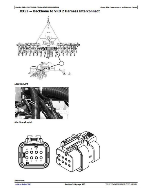
XX52 — Backbone to VRD 2 Harness Interconnect................1483
XX61 — SMVR to Vacuum 1 Harness Interconnect................1485
XX62 — SMVR to Vacuum 2 Harness Interconnect................1487
XX70 — CAN Tether to Electric Compressor Harness Interconnect................1489
XX71 — Backbone to Downforce Manifold Harness Interconnect................1491
XX72-A — Closing Wheel Harness CAN Interconnect................1493
XX72-B — Closing Wheel Harness Power Interconnect................1495
XX80 — SMVR to Fertilizer Controller Harness Interconnect................1497
XX80-LCL — Row Disconnects Interconnect LCL................1499
XX80-RCL — Row Disconnects Interconnect RCL................1501
XX80-S1 — Row Disconnects Interconnect S1................1503
XX80-S2 — Row Disconnects Interconnect S2................1505
XX81 — Backbone to Fertilizer Pressure Harness Interconnect................1507
XX85 — Backbone to Fertilizer Pump Harness Interconnect................1509
XX91 — Data Server Harness Interconnect................1511
XX101-XX132 — Backbone to Row Unit Harness Interconnects................1513
Group 40Y: Electrically Actuated Mechanical Devices................1056
XY1 — Center Frame Solenoid Connector................1518
XY5 — Left Marker Solenoid Connector................1521
XY6 — Right Marker Solenoid Connector................1524
XY8 — Auxiliary Fold Solenoid Connector................1527
XY9 — Main Fold Solenoid Connector................1530
XY11 — Rockshaft Solenoid 2 Connector................1533
XY15 — Rockshaft Solenoid 1 Connector................1536
XY18 — Plant Solenoid 1 Connector................1539
XY19 — Plant Solenoid 2 Connector................1542
XY20 — Plant Solenoid 3 Connector................1545
XY21 — Plant Solenoid 4 Connector................1548
XY22 — Transport Solenoid 1 Connector................1551
XY23 — Transport Solenoid 2 Connector................1554
XY24 — Transport Solenoid 3 Connector................1557
XY25 — Transport Solenoid 4 Connector................1560
XY26 — Hitch-Marker Solenoid 1 Connector................1563
XY27 — Hitch-Marker Solenoid 2 Connector................1565
XY41 — CCS Blower Solenoid Connector................1567
XY50L — Ground Drive Solenoid - Left Connector................1569
XY50R — Ground Drive Solenoid - Right Connector................1571
XY51 — VRD 1 Solenoid Connector................1573
XY52 — VRD 2 Solenoid Connector................1575
XY70 — Hydraulic Compressor Solenoid Connector................1577
XY71 — Fill Solenoid 1 Connector................1579
XY72 — Exhaust Solenoid 1 Connector................1582
XY73 — Fill Solenoid 2 Connector................1585
XY74 — Exhaust Solenoid 2 Connector................1588
XY76-1 — Fill Solenoid Valve 6 Connector................1591
XY76-2 — Exhaust Solenoid Valve 6 Connector................1593
XY77-1 — Fill Solenoid Valve 7 Connector................1595
XY77-2 — Exhaust Solenoid Valve 7 Connector................1597
XY81 — Fertilizer Pump Actuator Connector................1599
XY101-XY132 — Row Command Clutch Connectors................1601
Section 270: Hydraulics................1603
Group 20: Theory of Operation................1603
Auxiliary Hydraulics Hydraulic Theory of Operation................1606
CCS Blower Hydraulic Theory of Operation................1607
Drawbar Hitch Hydraulic Theory of Operation................1609
Field Lift Hydraulic Theory of Operation................1610
Fold Hydraulic Theory of Operation................1612
Hydraulic Compressor Hydraulic Theory of Operation................1614
Markers Hydraulic Theory of Operation................1615
Rockshafts Hydraulic Theory of Operation................1617
Transport Lift Hydraulic Theory of Operation................1618
Vacuum Hydraulic Theory of Operation................1619
Variable Rate Drive Hydraulic Theory of Operation................1620
Group 30: Schematics................1603
Auxiliary Hydraulics Hydraulic Schematic................1623
CCS Blower Hydraulic Schematic................1625
Drawbar Hitch Hydraulic Schematic................1627
Field Lift Hydraulic Schematic................1628
Fold Hydraulic Schematic................1630
Hydraulic Compressor Hydraulic Schematic................1631
Markers Hydraulic Schematic................1633
Rockshafts Hydraulic Schematic................1635
Transport Lift Hydraulic Schematic................1636
Vacuum Hydraulic Schematic................1638
Variable Rate Drive Hydraulic Schematic................1640
Group 50: Diagnostics................1603
Auxiliary Hydraulics Hydraulic Diagnostic................1644
CCS Blower Hydraulic Diagnostic................1646
Field Lift Hydraulic Diagnostic................1649
Fold Hydraulic Diagnostic................1654
Markers Hydraulic Diagnostic................1657
Rockshafts Hydraulic Diagnostic................1660
Transport Lift Hydraulic Diagnostic................1664
Hydraulic Compressor Hydraulic Diagnostic................1669
Vacuum Hydraulic Diagnostic................1672
Variable Rate Drive Hydraulic Diagnostic................1674
Section 279: Hydraulic Component Information................1676
Group 40C: Cylinder, Actuator, or Piston................1676
C1 — Left Wing Outside Cylinder................1681
C2 — Left Wing Inside Cylinder................1682
C3 — Left Center Outside Cylinder................1683
C4 — Left Center Inside Cylinder................1684
C5 — Right Center Inside Cylinder................1685
C6 — Right Center Outside Cylinder................1686
C7 — Right Wing Inside Cylinder................1687
C8 — Right Wing Outside Cylinder................1688
C9 — Left Fold Cylinder................1689
C10 — Right Fold Cylinder................1690
C11 — Left Marker Cylinder................1691
C12 — Right Marker Cylinder................1692
C13 — Left Rockshaft Cylinder................1693
C14 — Right Rockshaft Cylinder................1694
C15 — Drawbar Hitch Cylinder................1695
Group 40D: Check Valve................1676
D1 — Sense Check Kit 9A................1698
D2 — Sense Check Kit 9B................1700
D3 — Sense Check Kit 9C................1702
D4 — Sense Check Kit 9D................1704
D5 — Sense Check Kit 9E................1706
D13 — Left Rockshaft Check Valve................1708
D14 — Right Rockshaft Check Valve................1709
D41 — CCS Check Valve................1710
Group 40F: Filter................1676
F43 — Auxiliary Filter................1713
Group 40G: Valve Block, Assembly, or Gearcase................1676
G1 — Main Valve Manifold................1715
G13 — Left Rockshaft Manifold................1716
G14 — Right Rockshaft Manifold................1717
G15 — Drawbar Hitch Manifold................1718
G41 — CCS Blower Motor Case................1719
G72 — Hydraulic Compressor Motor Case................1720
Group 40H: Cooler................1677
H41 — Oil Cooler................1722
Group 40M: Motor................1677
M41 — CCS Blower Motor................1724
M51 — VRD 1 Motor................1725
M52 — VRD 2 Motor................1726
M61 — Vacuum 1 Motor................1727
M62 — Vacuum 2 Motor................1728
M70 — Hydraulic Compressor Motor................1729
Group 40O: Orifice................1677
O8 — Fold Orifice................1732
O9 — Left Fold Orifice................1734
O10 — Right Fold Cylinder Orifice................1735
O11 — Left Marker Orifice................1736
O12 — Right Marker Orifice................1737
O13 — Left Rockshaft Orifice................1738
O14 — Right Rockshaft Orifice................1739
O15 — Hitch Cylinder Orifice................1740
O61 — Vacuum 1 Orifice................1741
O62 — Vacuum 2 Orifice................1742
Group 40R: Reservoir Tank................1677
R41 — CCS Blower Reservoir................1744
Group 40V: Valve................1677
V1 — Flow Divider Valve................1747
V2 — Left Counterbalance Valve................1749
V3 — Right Counterbalance Valve................1751
V4 — Left Center Rephasing Valve................1753
V5 — Right Center Rephasing Valve................1755
V6 — Left Wing Lock Valve................1757
V7 — Right Wing Lock Valve................1759
V8 — Left Wing Rephasing Valve................1761
V9 — Right Wing Rephasing Valve................1763
V13 — Rockshaft Lock Valve................1765
V16 — Internal Relief Valve................1767
V17 — External Relief Valve................1769
V41 — CCS Flow Control Valve................1771
V43 — Auxiliary Selector Valve................1772
V51 — VRD 1 Pressure Sense Valve................1773
V52 — VRD 2 Pressure Sense Valve................1774
V61 — Vacuum 1 Flow Control Valve................1775
V62 — Vacuum 2 Flow Control Valve................1776
V71-1 — Load Sense Shuttle Valve................1777
V76 — Compressor Flow Control Valve................1778
Group 40X: Diagnostic Receptacle or Coupler................1678
X1P — Frame Pressure Coupler................1780
X1R — Frame Return Coupler................1781
X2P — Marker Pressure Coupler................1782
X2R — Marker Return Coupler................1783
X3P — Vacuum Pressure Coupler................1784
X3R — Vacuum Return Coupler................1785
X5P — VRD Pressure Coupler................1786
X5R — VRD Return Coupler................1787
X7 — Load Sense Coupler................1788
X8 — Case Drain Coupler................1789
X43P — Auxiliary Pressure Coupler................1790
X43R — Auxiliary Return Coupler................1791
X75 — Compressor Diagnostic Receptacle................1792
Group 40Y: Solenoid Valve................1678
Y1 — Center Frame Solenoid Valve................1795
Y5 — Left Marker Solenoid Valve................1797
Y6 — Right Marker Solenoid Valve................1799
Y8 — Auxiliary Fold Solenoid Valve................1801
Y9 — Main Fold Solenoid Valve................1803
Y11 — Rockshaft Solenoid Valve 2................1805
Y15 — Rockshaft Solenoid Valve 1................1807
Y18 — Plant Solenoid Valve 1................1809
Y19 — Plant Solenoid Valve 2................1811
Y20 — Plant Solenoid Valve 3................1813
Y21 — Plant Solenoid Valve 4................1815
Y22 — Transport Solenoid Valve 1................1817
Y23 — Transport Solenoid Valve 2................1819
Y24 — Transport Solenoid Valve 3................1821
Y25 — Transport Solenoid Valve 4................1823
Y26 — Hitch-Marker Solenoid Valve 1................1825
Y27 — Hitch-Marker Solenoid Valve 2................1826
Y41 — CCS Blower Solenoid Valve................1827
Y51 — VRD 1 Solenoid Valve................1828
Y52 — VRD 2 Solenoid Valve................1829
Y70 — Hydraulic Compressor Solenoid Valve................1830
Section 280: Pneumatics................1831
Group 20: Theory of Operation................1831
Closing Wheels Pneumatic Theory of Operation................1833
Downforce Pneumatic Theory of Operation................1834
Group 30: Schematics................1831
Closing Wheels Pneumatic Schematic................1838
Downforce Pneumatic Schematic................1840
Group 50: Diagnostics................1831
Closing Wheels Pneumatic Diagnostic................1852
Downforce Pneumatic Diagnostic................1861
Section 289: Pneumatic Components................1867
Group 40A: Accumulators................1867
A101-A132 — Row Air Springs................1870
A401-A432 — Closing Wheel Air Springs................1871
Group 40B: Sensors................1867
B70 — Tank Pressure Gauge................1874
B71 — Air Spring Pressure Sensor 1................1876
B72 — Air Spring Pressure Sensor 2................1878
B76 — Pressure Sensor 6................1880
B77 — Pressure Sensor 7................1881
Group 40D: Check Valves................1867
D70 — Compressor Outlet Check Valve................1884
Group 40F: Filters................1867
F70 — Compressor Inlet Filter................1887
Group 40G: Assembly Groups................1867
G70 — Pneumatic Downforce Manifold................1890
G71 — Compressor Assembly................1892
Group 40P: Pumps................1867
P70 — Compressor................1896
Group 40R: Reservoirs................1867
R70 — Air Tank................1899
Group 40S: Switches................1867
S70 — Tank Pressure Switch................1902
Group 40V: Valves................1867
V70 — Tank Condensate Drain................1905
V70-2 — Tank Relief Valve................1906
V71 — Pressure Increase Valve 1................1907
V72 — Pressure Decrease Valve 1................1909
V73 — Pressure Increase Valve 2................1911
V74 — Pressure Decrease Valve 2................1913
V75 — Fill Valve 1................1915
V76 — Fill Valve 2................1917
V76-1 — Pressure Increase Valve 6................1919
V76-2 — Pressure Decrease Valve 6................1920
V76-3 — Relief Valve 6................1921
V76-4 — Fill Valve 6................1922
V77-1 — Pressure Increase Valve 7................1923
V77-2 — Pressure Decrease Valve 7................1924
V77-3 — Relief Valve 7................1925
V77-4 — Fill Valve 7................1926
V77 — Relief Valve 1................1927
V78 — Relief Valve 2................1929
V79 — Relief Valve 3................1931
V80 — Manual Exhaust Valve................1933
Group 40X: Couplers or Diagnostic Receptacles................1868
X71 — Air Spring Gauge Coupler 1................1935
X72 — Air Spring Gauge Coupler 2................1936
X73 — Exhaust Vent 1................1937
X74 — Exhaust Vent 2................1938
Group 40Y: Solenoid Valves................1868
Y71 — Fill Solenoid Valve 1................1941
Y72 — Exhaust Solenoid Valve 1................1943
Y73 — Fill Solenoid Valve 2................1945
Y74 — Exhaust Solenoid Valve 2................1947
Y76-1 — Fill Solenoid Valve 6................1949
Y76-2 — Exhaust Solenoid Valve 6................1950
Y77-1 — Fill Solenoid Valve 7................1951
Y77-2 — Exhaust Solenoid Valve 7................1952
John Deere Planter with MaxEmerge 5 Row Units Models 1795 Diagnostic and Repair Service Manual (TM131719)
![]()