
John Deere 310SK (iT4/S3B) Backhoe Loader Operation and Test Service Manual (TM12459)
Complete Diagnosis and Test manual with Electrical Wiring Diagrams for John Deere 310SK (iT4/S3B) Backhoe Loader (SN:E219607-), with workshop information to maintain, diagnose, and rebuild like professional mechanics.
John Deere 310SK (iT4/S3B) Backhoe Loader (SN:E219607-) workshop Operation & Test manual includes:
* Numbered table of contents easy to use so that you can find the information you need fast.
* Detailed sub-steps expand on repair procedure information
* Numbered instructions guide you through every repair procedure step by step.
* Troubleshooting and electrical service procedures are combined with detailed wiring diagrams for ease of use.
* Notes, cautions and warnings throughout each chapter pinpoint critical information.
* Bold figure number help you quickly match illustrations with instructions.
* Detailed illustrations, drawings and photos guide you through every procedure.
* Enlarged inset helps you identify and examine parts in detail.
TM12459 - John Deere 310SK Backhoe Loader Technical Manual (Operation & Test).pdf
TM12459 - John Deere 310SK Backhoe Loader Technical Manual (Operation & Test).epub
Total Pages: 1,712 pages
File Format: PDF/EPUB/MOBI/AZW (PC/Mac/Android/Kindle/iPhone/iPad; bookmarked, ToC, Searchable, Printable)
Language: English
Covered models: 310SK (PIN: 1T0310SK**E219607-)
MAIN SECTIONS
Foreword
Manual Identification-READ THIS FIRST!
General Information
Safety
Diagnostics
Engine Control Unit (ECU) Diagnostic Trouble Codes
Standard Display Monitor (SDM) Diagnostic Trouble Codes
Transmission Control Unit (TCU) Diagnostic Trouble Codes
Vehicle Control Unit (VCU) Diagnostic Trouble Codes
Auxiliary Valve Controller (AVC) Diagnostic Trouble Codes
Sealed Switch Module (SSM) Diagnostic Trouble Codes
Operational Checkout Procedure
Operational Checkout Procedure
Engine
Theory of Operation
Diagnostic Information
Adjustments
Tests
Electrical System
System Information
System Diagrams
Sub-System Diagnostics
Monitor Operation
References
Power Train
Theory of Operation
Diagnostic Information
Adjustments
Tests
Hydraulic System
Theory of Operation
Diagnostic Information
Adjustments
Tests
Heating and Air Conditioning
Theory of Operation
Diagnostic Information
Tests
tm12459 - 310SK Backhoe Loader
Table of Contents
Foreword
Manual Identification—READ THIS FIRST!
Section 9000: General Information
Group 01: Safety
Recognize Safety Information
Follow Safety Instructions
Operate Only If Qualified
Wear Protective Equipment
Avoid Unauthorized Machine Modifications
Inspect Machine
Stay Clear of Moving Parts
Avoid High-Pressure Oils
Avoid High-Pressure Fluids
Work In Ventilated Area
Prevent Fires
Prevent Battery Explosions
Handle Chemical Products Safely
Decommissioning — Proper Recycling and Disposal of Fluids and Components
Prepare for Emergencies
Use Steps and Handholds Correctly
Start Only From Operator's Seat
Use and Maintain Seat Belt
Prevent Unintended Machine Movement
Prevent Unintended Machine Movement—If Equipped With Pilot Controls
Avoid Work Site Hazards
Keep Riders Off Machine
Avoid Backover Accidents
Avoid Machine Tipover
Add and Operate Attachments Safely
Use Special Care When Operating
Operating or Traveling On Public Roads
Inspect and Maintain ROPS
Park and Prepare for Service Safely
Service Cooling System Safely
Remove Paint Before Welding or Heating
Make Welding Repairs Safely
Drive Metal Pins Safely
Service Tires Safely
Section 9001: Diagnostics
Group 10: Engine Control Unit (ECU) Diagnostic Trouble Codes
Engine Control Unit (ECU) Diagnostic Trouble Codes
000029.03 - Hand Throttle
000029.04 - Hand Throttle
000029.14 - Hand Throttle
000091.03 - Foot Throttle
000091.04 - Foot Throttle
000091.14 - Foot Throttle
000111.07 - Engine Coolant Level
000190.16 - Engine Speed
000237.31 - Vehicle ID Number
000628.12 - Memory Error
000647.03 - Engine Fan Driver
000647.05 - Engine Fan Driver
001075.06 - Fuel Pump Control
001321.05 - Starter Relay
001321.06 - Starter Relay
001321.09 - Starter Relay
001321.16 - Starter Relay
001321.31 - Starter Relay
001639.01 - Fan Speed
002003.09 - No CAN From TCU
002003.19 - Flexpower Counter
002071.09 - No CAN From VCU
003353.31 - Alternator State
Group 20: Standard Display Monitor (SDM) Diagnostic Trouble Codes
Standard Display Monitor (SDM) Diagnostic Trouble Codes
000096.03 - Fuel Level Sensor
000096.04 - Fuel Level Sensor
000168.03 - Battery Voltage
000168.04 - Battery Voltage
000234.02 - Software Incorrect
000237.02 - VIN Mismatch
000237.13 - VIN Mismatch
000237.31 - VIN Missing
000628.12 - Memory Error
000629.12 - Controller Fault
000920.12 - Alarm Output
001196.11 - Antitheft
002000.09 - No CAN from ECU
002003.09 - No CAN from TCU
002071.09 - No CAN from VCU
002141.09 - No CAN from SSM
002228.09 - No CAN from HVC
002251.09 - No CAN from MTG
003509.03 - Sensor Supply 1
003509.04 - Sensor Supply 1
524082.07 - Display Buttons
Group 30: Transmission Control Unit (TCU) Diagnostic Trouble Codes
Transmission Control Unit (TCU) Diagnostic Trouble Codes
000070.14 - Park Brake
000177.00 - Trans Oil Temp
000177.04 - Trans Oil Temp
000191.00 - Transmission Speed
000191.03 - Transmission Speed
000191.04 - Transmission Speed
000191.16 - Transmission Speed
000525.02 - Requested Gear
000525.03 - Requested Gear
000525.04 - Requested Gear
000525.05 - Requested Gear
000604.04 - TCL Neutral SW
000617.07 - Park Brake Circuit
000618.07 - Park Brake Circuit
000629.12 - Controller Fault
000734.03 - Y1 Solenoid
000734.04 - Y1 Solenoid
000734.05 - Y1 Solenoid
000734.06 - Y1 Solenoid
000735.03 - Y2 Solenoid
000735.04 - Y2 Solenoid
000735.05 - Y2 Solenoid
000735.06 - Y2 Solenoid
000736.03 - Y3 Solenoid
000736.05 - Y3 Solenoid
000736.06 - Y3 Solenoid
000737.03 - Y4 Solenoid
000737.05 - Y4 Solenoid
000737.06 - Y4 Solenoid
000738.03 - Y5 Solenoid
000738.05 - Y5 Solenoid
000738.06 - Y5 Solenoid
000739.03 - Y6 Solenoid
000739.05 - Y6 Solenoid
000739.06 - Y6 Solenoid
000746.03 - Differential Lock
000746.05 - Differential Lock
000746.06 - Differential Lock
000746.31 - Differential Lock
000767.05 - TCL Reverse SW
000880.03 - Brake Lights
000880.05 - Brake Lights
000880.06 - Brake Lights
000903.05 - TCL Forward SW
001045.04 - Brake Light SW
002000.09 - No CAN From ECU
002023.09 - No CAN From SDM
002034.09 - No CAN From AVC
002071.09 - No CAN From VCU
002213.09 - No CAN From JSR
002392.03 - Brake Lights
002392.05 - Backup Lights
002392.06 - Backup Lights
002612.03 - MFWD Solenoid
002612.05 - MFWD Solenoid
002612.06 - MFWD Solenoid
004312.02 - TCL Selector
004312.03 - TCL Selector
004312.05 - TCL Selector
004312.06 - TCL Direction Driver
522379.03 - Park Brake
522379.04 - Park Brake
522379.05 - Park Brake
522379.06 - Park Brake
522382.03 - Reverse Alarm
522382.06 - Reverse Alarm
522405.03 - PB Pressure Switch
523689.04 - Diff Lock Switch
523689.07 - Diff Lock Switch
523702.07 - Flexpower
523702.08 - Flexpower
523702.09 - Flexpower
523702.10 - Flexpower
523769.07 - MFWD Switch
524172.03 - Clutch Disconnect
524172.04 - Clutch Disconnect
524172.07 - Clutch Disconnect
524172.09 - Clutch Disconnect
Group 40: Vehicle Control Unit (VCU) Diagnostic Trouble Codes
Vehicle Control Unit (VCU) Diagnostic Trouble Codes
000168.03 - Battery Voltage
000168.04 - Battery Voltage
000234.02 - Software Incorrect
000237.02 - VIN Mismatch
000237.13 - VIN Mismatch
000237.31 - VIN Missing
000628.12 - Memory Error
000629.12 - Controller Fault
000677.03 - Start Relay
000677.05 - Start Relay
000677.06 - Start Relay
001237.31 - Engine Shutdown
001321.16 - Starter Relay
001638.00 - Hyd Temp Sensor
001638.04 - Hyd Temp Sensor
001638.16 - Hyd Temp Sensor
001713.00 - Hyd Oil Restriction
001762.03 - Hydraulic Pressure
001762.04 - Hydraulic Pressure
002141.09 - No CAN from SSM
002142.09 - No CAN from SSM
002228.09 - No CAN from HVC
002228.12 - EH Watchdog
002350.03 - Drive Lights
002350.05 - Drive Lights
002350.06 - Drive Lights
002354.03 - Front Work Lights
002354.05 - Front Work Lights
002354.06 - Front Work Lights
002356.03 - Front Work Lights
002356.05 - Front Work Lights
002356.06 - Front Work Lights
002360.03 - Rear Work Lights
002360.05 - Rear Work Lights
002360.06 - Rear Work Lights
002362.03 - Rear Work Lights
002362.05 - Rear Work Lights
002362.06 - Rear Work Lights
002366.03 - Rear Work Lights
002366.05 - Side Work Lights
002366.06 - Side Work Lights
002368.03 - Left Flasher
002368.05 - Left Flasher
002368.06 - Left Flasher
002370.03 - Right Flasher
002370.05 - Right Flasher
002370.06 - Right Flasher
002378.03 - Marker Light
002378.05 - Marker Light
002378.06 - Marker Light
0002641.03 - EH Horn
0002641.05 - EH Horn
0002641.06 - EH Horn
002875.03 - Hazard Wakeup
002876.07 - Turn Signal Switch
003416.03 - Right Door Sw
003416.04 - Right Door Sw
003509.03 - Sensor Supply 1
003509.04 - Sensor Supply 1
003510.03 - Sensor Supply 2
003510.04 - Sensor Supply 2
003511.03 - Sensor Supply 3
003511.04 - Sensor Supply 3
003997.03 - Accessory Relay
003997.05 - Accessory Relay
003997.06 - Accessory Relay
520416.03 - Valve Power
520416.04 - Valve Power
520416.05 - Valve Power
520546.03 - Pilot Enable Switch
520546.07 - Pilot Enable Switch
520688.03 - Pilot Enable Driver
520688.05 - Pilot Enable Driver
520688.06 - Pilot Enable Driver
520695.02 - Auxiliary Switch
520696.03 - Pattern Select Driver
520696.05 - Pattern Select Driver
520696.06 - Pattern Select Driver
520697.03 - Loader Coupler Press
520697.05 - Loader Coupler Press
520697.06 - Loader Coupler Press
520708.03 - HVC Valve Power
520708.06 - HVC Valve Power
520713.03 - Seat Position
520713.04 - Seat Position
520713.07 - Seat Position
520713.12 - Seat Position
520713.13 - Seat Position
520714.06 - Bucket Level LEDs
522426.03 - Rear Wiper Park
522426.04 - Rear Wiper Park
522427.03 - Front Wiper Park
522427.04 - Front Wiper Park
522433.03 - Rear Wiper
522433.05 - Rear Wiper
522433.06 - Rear Wiper
522434.03 - Front Wiper Low
522434.05 - Front Wiper Low
522434.06 - Front Wiper Low
522435.03 - Front Wiper Hi
522435.05 - Front Wiper Hi
522435.06 - Front Wiper Hi
522438.03 - Loader Coupler
522438.05 - Loader Coupler
522438.06 - Loader Coupler
522797.03 - Front Washer Pump
522797.05 - Front Washer Pump
522797.06 - Front Washer Pump
523597.03 - Beacon Light Driver
523597.05 - Beacon Light Driver
523597.06 - Beacon Light Driver
523911.03 - Pump Control
523911.04 - Pump Control
523911.05 - Pump Control
523911.06 - Pump Control
523911.13 - Pump Control
523948.03 - Ride Control
523948.05 - Ride Control
523948.06 - Ride Control
Group 50: Auxiliary Valve Controller (AVC) Diagnostic Trouble Codes
Auxiliary Valve Controller (AVC) Diagnostic Trouble Codes
000234.02 - Software Incorrect
000629.12 - Controller Fault
002664.03 - Ldr Aux Roller
002664.04 - Ldr Aux Roller
002664.07 - Ldr Aux Roller
002664.12 - Ldr Aux Roller
002724.07 - Left Joystick
003509.03 - Sensor Supply 1
003509.04 - Sensor Supply 1
520542.03 - CAN Bus
520543.04 - CAN Bus
523404.00 - Loader Aux Press
523404.01 - Loader Aux Press
523571.04 - Valve Power 2
523769.03 - MFWD Switch
523769.04 - MFWD Switch
523938.03 - Loader Aux Sol A
523938.04 - Loader Aux Sol A
523938.05 - Loader Aux Sol A
523938.06 - Loader Aux Sol A
523939.03 - Loader Aux Sol B
523939.04 - Loader Aux Sol B
523939.05 - Loader Aux Sol B
523939.06 - Loader Aux Sol B
524010.03 - Selective Flow
524010.04 - Selective Flow
524010.05 - Selective Flow
524010.06 - Selective Flow
Group 60: Sealed Switch Module (SSM) (OC4) Diagnostic Trouble Codes
Sealed Switch Module (SSM) Diagnostic Trouble Codes
000629.12 - Controller Fault
002634.04 - Ignition Relay
002634.05 - Ignition Relay
523850.04 - SSM Button 15
523850.09 - SSM Button 15
523852.04 - SSM Button 14
523852.09 - SSM Button 14
523854.04 - SSM Button 13
523854.09 - SSM Button 13
523855.04 - SSM Button 12
523855.09 - SSM Button 12
523856.04 - SSM Button 11
523856.09 - SSM Button 11
523857.04 - SSM Button 10
523857.09 - SSM Button 10
523858.04 - SSM Button 9
523858.09 - SSM Button 9
523860.04 - SSM Button 8
523860.09 - SSM Button 8
523861.04 - SSM Button 7
523861.09 - SSM Button 7
523862.04 - SSM Button 6
523862.09 - SSM Button 6
523863.04 - SSM Button 5
523863.09 - SSM Button 5
523864.04 - SSM Button 4
523864.09 - SSM Button 4
523865.04 - SSM Button 3
523865.09 - SSM Button 3
523867.04 - SSM Button 2
523867.09 - SSM Button 2
523868.04 - SSM Button 1
523868.09 - SSM Button 1
Section 9005: Operational Checkout Procedure
Group 10: Operational Checkout Procedure
Operational Checkout Procedure
Section 9010: Engine
Group 05: Theory of Operation
John Deere Engine Operation
Engine Cooling System Operation
Cold Start Aid System Operation
Group 15: Diagnostic Information
John Deere Engine Operation
Engine Cooling System Component Location
Engine Fuel System Component Location
Engine Intake and Exhaust Component Location
Group 20: Adjustments
John Deere Engine Operation
Service Filter Cleaning
Group 25: Tests
John Deere Engine Operation
Fluid Sampling Procedure—If Equipped
Engine Speed Check
Air in Fuel Test
Engine Thermostat Test
Thermal Bypass Valve Test
Section 9015: Electrical System
Group 05: System Information
Electrical Diagram Information
Electrical Schematic Symbols
Group 10: System Diagrams
Fuse and Relay Location and Specifications
System Functional Schematic, Wiring Diagram, and Component Location Legend
System Functional Schematic and Section Legend
Horn and Coolant Level Harness (W7) Component Location
Horn and Coolant Level Harness (W7) Wiring Diagram
Glow Plug Harness (W9) Component Location
Glow Plug Harness (W9) Wiring Diagram
Engine Harness (W10) Component Location
Engine Harness (W10) Wiring Diagram
Engine Interface Harness (W11) Component Location
Engine Interface Harness (W11) Wiring Diagram
Transmission Harness (W13) Component Location
Transmission Harness (W13) Wiring Diagram
Cab Harness (W14) Component Location
Cab Harness (W14) Wiring Diagram
Canopy Harness (W15) Component Location
Canopy Harness (W15) Wiring Diagram
Roof Harness (W17) Component Location
Roof Harness (W17) Wiring Diagram
Radio Harness (W18) Component Location
Radio Harness (W18) Wiring Diagram
Heater and Air Conditioner Harness (W19) Component Location
Heater and Air Conditioner Harness (W19) Wiring Diagram
Loader Coupler Solenoid Harness (W26) Component Location
Loader Coupler Solenoid Harness (W26) Wiring Diagram
Ride Control Solenoid Harness (W27) Component Location
Ride Control Solenoid Harness (W27) Wiring Diagram
Selective Flow Solenoid Harness (W28) Component Location
Selective Flow Solenoid Harness (W28) Wiring Diagram
Loader Auxiliary Solenoid Harness (W29) Component Location
Loader Auxiliary Solenoid Harness (W29) Wiring Diagram
Pilot Enable Pattern Select Valve Harness (W30) Component Location
Pilot Enable Pattern Select Valve Harness (W30) Wiring Diagram
Pilot Enable Switch Harness (W31) Component Location
Pilot Enable Switch Harness (W31) Wiring Diagram
Return-to-Dig Harness (W32) Component Location
Return-to-Dig Harness (W32) Wiring Diagram
Air Conditioner Compressor Clutch Harness (W39) Component Location
Air Conditioner Compressor Clutch Harness (W39) Wiring Diagram
Blower Mode Door Motor Harness (W40) Component Location
Blower Mode Door Motor Harness (W40) Wiring Diagram
Handheld Selective Flow Control Harness (W44) Component Location—If Equipped
Handheld Selective Flow Control Harness (W44) Wiring Diagram—If Equipped
Fan Speed Sensor Harness (W48) Component Location—If Equipped
Fan Speed Sensor Harness (W48) Wiring Diagram—If Equipped
Modular Telematics Gateway (MTG) Harness (W6002) Component Location
Modular Telematics Gateway (MTG) Harness (W6002) Wiring Diagram
Satellite (SAT) Harness (W6003) Component Location
Satellite (SAT) Harness (W6003) Wiring Diagram
Power and Ground Component Location
Group 15: Sub-System Diagnostics
Start and Charge Circuit Theory of Operation
Controller Area Network (CAN) Circuit Theory of Operation
Engine Control Unit (ECU) Circuit Theory of Operation
Exhaust Aftertreatment Circuit Theory of Operation
Vehicle Control Unit (VCU) Circuit Theory of Operation
Transmission Control Circuit Theory of Operation
Hydraulic System Circuit Theory of Operation
Horn, Lights, and Beacon Circuit Theory of Operation
Wiper and Washer Circuit Theory of Operation
Standard Display Monitor (SDM) Circuit Theory of Operation
JDLink™ Circuit Theory of Operation
Group 16: Monitor Operation
Standard Display Monitor (SDM)—Service Menu
Standard Display Monitor (SDM)—Clear Codes
Standard Display Monitor (SDM)—Diagnostics
Standard Display Monitor (SDM)—Exhaust Filter
Standard Display Monitor (SDM)—Main Menu Visible or Hidden
Standard Display Monitor (SDM)—Restore Monitor Defaults
Standard Display Monitor (SDM)—Machine Options
Standard Display Monitor (SDM)—Setting Hour Meter
Security System Enable-Disable
Security System Configuration
Security System Operation
Group 20: References
Electrical Component Specifications
Service ADVISOR™ Connection Procedure
JDLink™ Connection Procedure
Reading Diagnostic Trouble Codes (DTCs)
Diagnostic Trouble Code (DTC) Monitor Messages
Intermittent Diagnostic Trouble Code (DTC) Diagnostics
Controller Area Network (CAN) Circuit Test
Controller Area Network (CAN) Resistor Test
Alternator Test
Wire Harness Test
Sensor Circuit Test
Transmission Control Circuit Test
Transmission Solenoid Circuit Test
Transmission Control Lever (TCL) Test
Transmission Solenoid Check
Throttle Position Sensor Test
Engine Speed Control Pedal Test
Vehicle Control Unit (VCU) Output Test
Seat Position Sensor Remove and Install
Controller Remove and Install
Section 9020: Power Train
Group 05: Theory of Operation
Power Train Overview
Transmission Pump Operation
Torque Converter Operation
Transmission Filter Operation
Clutch Modulation Operation
Clutch Pack Operation
Transmission Gear Flow
Transmission Clutch Engagement and Solenoid Activation
Differential Operation
Differential Lock Operation
Mechanical Front Wheel Drive (MFWD) Operation—If Equipped
Mechanical Front Wheel Drive (MFWD) Differential Operation—If Equipped
Park Brake Operation
Service Brake Operation
Power Boost Service Brake Valve Operation
Group 15: Diagnostic Information
Hydraulic Circuit—Symbols
Power Train Component Location
Power Train Schematic—Neutral
Power Train Schematic—First Forward
Diagnose Transmission Malfunctions
Transmission Slippage
Machine Lacks Power or Moves Slow
Transmission Overheats
Excessive Power Train Noise
No Power to Mechanical Front Wheel Drive (MFWD)
No Power to One Wheel of Mechanical Front Wheel Drive (MFWD)
No Differential Lock Operation
Differential Lock Slips or Chatters When Engaged
Differential Lock Will Not Release
Rear Axle Overfilled With Oil
Poor Service Brakes
Brake Pedal Hard to Push
Service Brakes Will Not Release
Service Brakes Chatter or Noisy
Park Brake Will Not Hold
Park Brake Will Not Release
Group 20: Adjustments
Mechanical Park Brake Release—Towing
Service Brake Pedal Adjustment
Service Brake Bleed Procedure
Tracking Angle Check and Adjust
Toe-In Check and Adjust
Steering Angle Check and Adjust
Group 25: Tests
Transmission Oil Warm-Up Procedure
Transmission Oil Sampling Procedure—If Equipped
Transmission Overall Test Connections, Ports, and Locations
Torque Converter Stall Speed Test
Torque Converter Inlet Pressure Test
Power Boost Service Brake Valve Leakage Test
Park Brake Release Pressure Test
Transmission System Pressure Test
Service Brake Boost Pressure Test
Clutch Pressure Test
Differential Lock Pressure Test
Mechanical Front Wheel Drive (MFWD) Pressure Test
Cooler In and Cooler Out Pressure Test
Solenoid Circuit Leakage Test
Transmission Pump Flow Test
Section 9025: Hydraulic System
Group 05: Theory of Operation
Hydraulic System Operation
Hydraulic Pump Operation
Unloading Valve Operation
Hydraulic Filter Operation
Steering Valve Operation
Ride Control Operation—If Equipped
System Relief Valve Operation
Circuit Relief Valve without Anticavitation—Loader and Backhoe
Circuit Relief Valve with Anticavitation—Backhoe Swing, Boom Lower
Circuit Relief Valve with Anticavitation—Backhoe Bucket Curl and Loader Bucket Dump
Backhoe Control Valve Operation
Pilot Control Valve Operation—If Equipped
Pilot Enable and Pattern Select Valve Operation—If Equipped
Loader Auxiliary Control Operation—If Equipped
Loader and Stabilizer Control Valve Operation
Attachment Coupler Hydraulic Operation
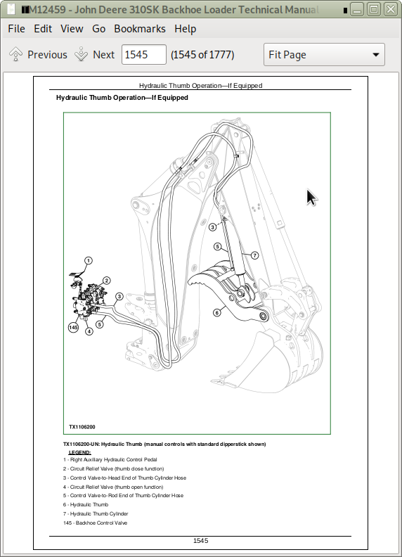
Hydraulic Thumb Operation—If Equipped
Group 15: Diagnostic Information
Hydraulic System Schematic
Hydraulic System Component Location
Slow Steering Hydraulics
No Steering Hydraulics, Loader Hydraulics OK
Hard Steering, Loader Hydraulics OK
Steering Valve Does Not Return to Neutral
No Response When Steering Wheel is Turned, Loader Hydraulics OK
Machine Turns in Opposite Direction
Excessive Vibration of the Steering Wheel
Machine Turns When Steering Valve is in Neutral
Steering Wheel Kickback
Excessive Steering Wheel Turns to Steer Machine
Erratic (“Spongy”) Steering
Steering Wheel "Locks" Up
Poor Centering of Steering Wheel (Wheels Continue to Move After Steering Wheel is Stopped)
Steering Wheel or Front Wheels Slowly Turn by Themselves When Using Backhoe or Loader
Steering Wheel Turns Apply Rear Axle Service Brakes
Steering Wheel Turns Freely With No Resistance or Action On Steered Wheels
Steering Wheel Turns With Slight Resistance and No Action On Steered Wheels
Wander—Machine Will Not Stay in a Straight Line
No Loader or Steering Hydraulics
No Loader Hydraulics
Low Loader Hydraulic Power
Low Hydraulic Power
Engine Pulls Down Excessively During Loader Operation
Engine Pulls Down Excessively During Backhoe Operation
Slow Hydraulic Functions
Backhoe Operates Slowly in One Function
Loader Operates Slowly in One Function
No Backhoe Power in One Function
No Loader Power in One Function
No Stabilizer Hydraulics
Slow Loader and Backhoe Hydraulics
Low Hydraulic Power (Low Hydraulic Pressure)
Hydraulic Function Makes "Chattering" Noise
Functions Drift
Control Valve Sticks or Works Hard
Hydraulic Oil Overheats
Foaming Oil
Hydraulic Pump Leaking
Excessive Pump Noise
Attachment Coupler Not Working
Group 20: Adjustments
Backhoe Control Lever to Valve Linkage (Two Lever) Adjustment
Backhoe Control Lever to Valve Linkage (Four Lever) Adjustment—If Equipped
Auxiliary Selective Flow Control Valve Adjustment—If Equipped
Pilot Control Pressure Adjustment
Pilot Enable and Pattern Select Valve Accumulator Discharge Procedure
Loader Bucket Self-Leveling Linkage and Return-To-Dig Switch Adjustment
Loader and Stabilizer Lever Adjustment
Ride Control Accumulator Charge Procedure
Ride Control Accumulator Charge Check Procedure
Ride Control Accumulator Hydraulic Pressure Release Procedure
Group 25: Tests
JT02156A Digital Pressure and Temperature Analyzer Kit Installation
Hydraulic Oil Warm-Up Procedure
Fluid Sampling Procedure—If Equipped
Hydraulic Oil Sampling Procedure—If Equipped
Hydraulic Circuit Pressure Release
Hydraulic Pump Flow Test
System Relief Valve Pressure Test
Hydraulic Pump Unloading Relief Valve Pressure Test
Pilot Control Pressure Test
Pilot Control Accumulator Charge Pressure Test
Hydraulic Oil Cooler Restriction Test
Circuit Relief Valve Test—With Remote Pump
Steering System Leakage Test
Steering Cylinder Leakage Test
Function Drift Test
Hydraulic Cylinder Leakage Test
Loader and Stabilizer Control Valve Lockout Leakage Test
Section 9031: Heating and Air Conditioning
Group 05: Theory of Operation
Air Conditioning System Cycle Of Operation
Group 15: Diagnostic Information
Air Conditioning and Heater System Component Location
Air Conditioning System Does Not Operate
Air Conditioner Does Not Cool Interior of Cab
Air Conditioner Runs Constantly, Too Cold
Heater System Does Not Operate
Heater Does Not Warm Interior of Cab
Interior Windows Continue to Fog
Group 25: Tests
Refrigerant Cautions and Proper Handling
R134a Refrigerant Cautions
R134a Oil Charge Capacity
R134a Refrigerant Charge Capacity
Air Conditioner and Heater Operational Checks
Air Conditioner Compressor Clutch Test
Air Conditioner High/Low Pressure Switch Test
Air Conditioner Freeze Control Switch Test
R134a Air Conditioning System Test
Operating Pressure Diagnostic Chart
Expansion Valve Test
Blower Motor Speed Switch Test
Blower Motor Resistor Test
Blower Motor Test
Air Conditioning Mode Switch Test
Air Conditioning System Leak Test
Refrigerant Hoses and Tubing Inspection
John Deere 310SK (iT4/S3B) Backhoe Loader Operation & Test Service Manual (TM12459)
![]()