
John Deere Tracks Tractors 9300T, 9320T, 9400T, 9420T, 9520T, 9620T Repair Service Manual (TM1782)
Complete Repair Service Technical Manual for John Deere Tracks Tractors 9300T, 9400T, 9320T, 9420T, 9520T, 9620T, with workshop information to maintain, repair, service like professional mechanics.
John Deere Tracks Tractors 9300T, 9400T, 9320T, 9420T, 9520T, 9620T workshop technical manual (repair) includes:
* Numbered table of contents easy to use so that you can find the information you need fast.
* Detailed sub-steps expand on repair procedure information
* Numbered instructions guide you through every repair procedure step by step.
* Bold figure number help you quickly match illustrations with instructions.
* Detailed illustrations, drawings and photos guide you through every procedure.
* Enlarged inset helps you identify and examine parts in detail.
tm1782 - John Deere 9300T, 9400T, 9320T, 9420T, 9520T and 9620T Tractors Repair Technical Manual.pdf
tm1782 - John Deere 9300T, 9400T, 9320T, 9420T, 9520T and 9620T Tractors Repair Technical Manual.epub
Total Pages: 1,629 pages
File Format: PDF/EPUB/MOBI/AZW (PC/Mac/Android/Kindle/iPhone/iPad; bookmarked, ToC, Searchable, Printable)
Language: English
MAIN SECTIONS
Notice to the Dealer
Dealer Predelivery Information Form
General Information
Safety
General Information
Engine
Component Removal and Installation
Engine Repair
Fuel, Air, and Cooling Systems
Diesel Fuel System
Air Intake and Exhaust Systems
Engine Cooling System
Oil Coolers
Electrical
Connectors
Wiring Harness Routings
Charging Circuit
Starting Circuit
Relays, Fuses, Solenoids, and Switches
Monitoring Systems and Sensors
Armrest Control
Implement and Accessory Connectors
Convenience and Accessory Components
Power Shift Transmission (PST)
Component Removal and Installation
In-Tractor Repair
Transmission Repair
Transmission Cleanup
Clutch Control
Mechanical Shift Transmission (MST)
Component Removal and Installation
Transmission Oil Filter Relief Valve Housing
Transmission Control Valve Housing
Transmission Pump
Transmission Front Cover
Hi-Lo Clutch and Brake
Hi-Lo Planetary
Spacer Housing
Traction Clutch
Transmission Gear Drives
Transmission Cleanup
Shift Levers and Linkage
Drive Systems
Component Removal and Installation
Engine Coupler
Drive Shafts
PTO Clutch
PTO Clutch Valve and Linkage
PTO Drop Box
Rear Axle Assembly
Component Removal
Outboard Planetary Final Drive
Outboard Planetary Service Brakes
Outboard Planetary Park Brake (PST Tractor S.N. -902241)
Wheel Hub and Axle Housing
Steering Differential Carrier
Differential Case Steering Gears
Differential Case Drive Gears
Input Pinion Housing
Steering and Brakes
Steering Column
Steering Wheel Position Input Assembly
Steering Pump
Steering Pump Drive Gearbox
Steering Motor
Brake Valve
Brake Components
Park Brake-9020T
Hydraulics
Hydraulic System Repair
Hydraulic Pump
Axle Lubrication Pump
Filter Housings and Control Valves
Hitch Valve, Selective Control Valves, and Couplers-9000T Series
Hitch Valve, Selective Control Valves, and Couplers-9020T Series
Hitch
Miscellaneous
Hood and Side Panels
Platform Step Assembly
Frames
Hitch Frame and Drawbar
Operator Station
Cab Removal and Installation
Heating, Ventilating, and Air Conditioning (HVAC)
Air Conditioning System
Air Suspension Seat
Cab Door and Windshield
Track Frame and Components
Tracks
Tension Cylinder and Accumulator
Track Frame
Dealer Fabricated Tools
Fabricated Tools
tm1782 - 9300T, 9400T, 9320T, 9420T, 9520T and 9620T Tractors Repair
Table of Contents
Notice to the Dealer
Dealer Predelivery Information Form
Section 10: General Information
Group 05: Safety
Follow Safety Instructions
Recognize Safety Information
Practice Safe Maintenance
Handle Fluids Safely—Avoid Fires
Prevent Battery Explosions
Prepare for Emergencies
Prevent Acid Burns
Handle Agricultural Chemicals Safely
Avoid High-Pressure Fluids
Park Machine Safely
Support Machine Properly
Wear Protective Clothing
Protect Against High Pressure Spray
Work in Clean Area
Service Machines Safely
Work In Ventilated Area
Illuminate Work Area Safely
Replace Safety Signs
Use Proper Lifting Equipment
Avoid Harmful Asbestos Dust
Avoid Heating Near Pressurized Fluid Lines
Remove Paint Before Welding or Heating
Use Proper Tools
Construct Dealer-Made Tools Safely
Dispose of Waste Properly
Live With Safety
Protect Against Noise
Service Accumulator Systems Safely
Wait Before Opening High-Pressure Fuel System
Group 10: General Information
General Specifications
Overall Dimensions
Sealants and Adhesives Cross-Reference Chart
Metric Bolt and Screw Torque Values
Unified Inch Bolt and Screw Torque Values
Identifying Zinc-Flake Coated Fasteners
Glossary of Terms
Section 20: Engine
Group 00: Component Removal and Installation
Essential or Recommended Tools
Specifications
Engine Identification
Remove and Install Engine
Group 05: Engine Repair
Repair Engine—Use CTM
Specifications
Section 30: Fuel, Air, and Cooling Systems
Group 05: Diesel Fuel System
Essential or Recommended Tools
Specifications
Fuel Tank Components
Remove and Install Left Fuel Tank
Remove and Install Right Fuel Tank
Remove and Install Center Fuel Tank
Replace Fuel Filter, Fuel Pump, and Bleed Fuel System
Group 10: Air Intake and Exhaust Systems
Specifications
Install Muffler
Air Intake Pipe Connections
Turbocharger Inlet Hose
Air Intake Pipe Installation
Inspect Air Intake System
Service Air Intake System
Group 15: Engine Cooling System
Essential or Recommended Tools
Specifications
Test Radiator and Coolant Tank
Test Radiator Cap
Remove and Install Radiator
Remove and Install Aftercooler
Remove and Install Viscous Fan Drive
Inspect Belt Tensioner
Drive Belt Routings
Group 20: Oil Coolers
Specifications
Remove and Install Axle-Transmission Oil Cooler—9000T
Remove and Install Hydraulic Oil Cooler—9000T
Remove and Install Oil Cooler—9020T
Leak Test Oil Coolers
Section 40: Electrical
Group 05: Connectors
Essential or Recommended Tools
Other Material
Use Electrical Insulating Compound
Using High-Pressure Washers
Repair AMP Connector
Remove Connector Body from Blade Terminals
Repair CINCH Connectors
Repair 32 and 48 Way CINCH Connectors
Repair CPC CPC is a trademark of AMP Incorporated Blade Type Connectors
Repair CPC CPC is a trademark of AMP Incorporated , Large MATE-N-LOC MATE-N-LOC is a trademark of AMP Incorporated and METRIMATE METRIMATE is a trademark of AMP Incorporated Pin Type Connectors
Repair DEUTSCH DEUTSCH is a trademark of Deutsch Company Connectors
Repair Small MATE-N-LOC MATE-N-LOC is a trademark of AMP Incorporated Socket Connector
Repair Small MATE-N-LOC MATE-N-LOC is a trademark of AMP Incorporated Pin Connector
Repair (Pull Type) METRI-PACK METRI-PACK is a trademark of Delphi Packard Electric Systems Connectors
Repair (Push Type) METRI-PACK METRI-PACK is a trademark of Delphi Packard Electric Systems Connectors
Repair SUMITOMO™ Connectors
Repair Weather Pack Weather Pack is a trademark of Packard Electric Connector
Repair YAZAKI™ Connectors
Group 10: Wiring Harness Routings
Wire Number and Color Codes
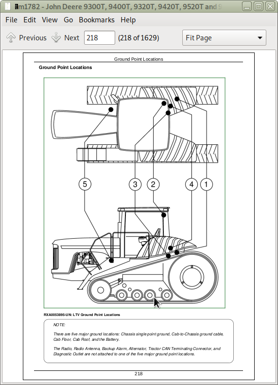
Ground Point Locations
# 1 Chassis Single Point Ground Stud
# 2 Cab-To-Chassis Ground
# 3 Cab Ground (Floor)
# 4 Cab Ground (Roof)
# 5 Battery Ground
Miscellaneous Grounds
Engine/Chassis Harness Routing and Component Identification—Front—MST
Engine/Chassis Harness Routing and Component Identification—Rear—MST
Engine/Chassis Harness Routing and Component Identification—Front—PST
Engine/Chassis Harness Routing and Component Identification—Rear—PST
Engine/Chassis Harness Routing and Component Identification—Front—European
Engine/Chassis Harness Routing and Component Identification—Rear—European
Transmission Harness Routing and Component Identification—9020T Series w/PST (S.N. —902241)
Transmission Harness Routing and Component Identification—9020T Series w/PST (S.N. 902242— )
Roof Harness Routing and Component Identification—North American
Roof Harness Routing and Component Identification—European
Cab Harness Routing and Component Identification—MST
Cab Harness Routing and Component Identification—PST
Cab Harness Routing and Component Identification—European
GREENSTAR GREENSTAR is a trademark of Deere & Company Harness Routing and Component Identification
Remote Mirror Harness Routing and Component Identification
Group 15: Charging Circuit
Disconnect Electrical Circuit
Repair Alternator—Use CTM
Exploded View—Alternator
Replace Alternator
Alternator Power Cable Routing
Replace Batteries
Group 20: Starting Circuit
Specifications
Repair Starter—Use CTM77
Remove and Install Starter
Replace Fusible Link
Remove and Install Start Circuit Relay
Group 25: Relays, Fuses, Solenoids, and Switches
Essential or Recommended Tools
Specifications
General Repair Procedures—Solenoids
Disconnect Electrical Circuit
Load Center Fuses
Load Center Relays and Diodes
Replace Starting Aid Solenoid
Replace Two-Speed Clutch Hi-Lo Solenoid—MST
Replace Solenoid Valves—PST
Replace SCV Solenoids
Replace Hitch Valve Solenoids
Replace Park Brake Valve Solenoids—9020T Series w/PST (S.N. —902241)
Replace Park Brake Valve Solenoids—9020T Series w/PST (S.N. 902242— )
Exploded View—Right Console Controls and Switches—9000T
Exploded View—Right Console Controls and Switches—9020T
Replace Right Console Switches
Replace Engine Oil Pressure Switch
Replace Starting Aid and Ignition Switch
Replace Neutral Start Switch—PST
Neutral Start Switch—MST
Replace Reverse Switches—MST
Replace Park Brake Valve Pressure Switch—9020T Series w/PST (S.N. —902241)
Replace Park Brake Valve Pressure Sensor—9020T Series w/PST (S.N. 902242— )
Replace Hand Brake Switch and Potentiometer European 9020T Series w/PST (S.N. —902241)
Replace Rear PTO Switch
Replace Dome Light Switch
Replace Cab Door Light Switch
Replace Beacon Light Switch
Replace Seat Raise/Lower Switch
Replace Operator Presence Seat Switch
Replace External Hitch Raise/Lower Switch
Replace A/C High- and Low-Pressure Switches
Replace A/C Deicing Switch and Blower Motor Resistor
Group 30: Monitoring Systems and Sensors
Essential or Recommended Tools
Other Material
Specifications
Replace Instrument Control Unit and SCV Set-up Panel
Replace Bulbs In Instrument Control Unit (ICU)
Replace Bulbs In SCV Set-up Panel (SUP)
Replace Corner Post Display and Bulbs
Replace Steering Column Module Bulbs
Replace Steering Column Module
Replace Control Units—9000T
Replace Control Units—9020T
Replace Engine Cam Speed Sensor
Replace Engine Crank Speed Sensor
Replace Engine Coolant Temperature Sensors
Replace Air Filter Restriction Sensor
Replace Fuel Level Sensor
Replace Fuel Temperature Sensor
Remove, Inspect, and Adjust Clutch Position Sensor
Replace Radar Sensor
Replace Wheel Speed Sensor—MST
Replace Transmission Oil Filter Restriction Sensor—MST
Replace Transmission Lube Oil Pressure Sensor—MST
Replace Axle Lube Filter Restriction Sensor (S.N. -902087)
Replace Axle Lube Pressure Sensor (S.N. -902087)
Replace Steering Case Pressure Sensor (S.N. 902088- )
Replace Steering Motor Speed Sensor
Replace Steering Filter Restriction Sensor
Replace Steering Oil Temperature Sensor
Replace Track Tension Pressure Sensor
Replace Hydraulic Oil Temperature Sensor
Replace Hydraulic Oil Reservoir Level Sensor
Replace Hydraulic Oil Filter Restriction Sensor
Replace Hitch Position Sensor
Replace Draft-Sensing Sensor
Adjust Draft-Sensing Sensor
CLIMATRAK CLIMATRAK is a trademark of Deere & Company Wire Harness and Component Identification
Replace Outlet Duct Temperature Sensor
Replace Cab Temperature Sensor
Replace Evaporator Temperature Sensor
Group 35: Armrest Control
Armrest Test Procedures
Exploded View—Armrest Control—9000T
Exploded View—Armrest Control—9020T
Replace Armrest Control Assembly
Replace Armrest Control Unit (ACU)
Replace Armrest Controls—9000T
Replace Armrest Controls—9020T
Exploded View—Engine Speed Control
Exploded View—Transmission Control—PST
Exploded View—Hi-Lo Clutch Control—MST
Replace Hitch Control
Exploded View—SCV Control Lever
Group 40: Implement and Accessory Connectors
Replace Seven-Terminal Outlet Socket
TouchSet Depth Control Connector
Diagnostic Program Connector
ECU Diagnostic Connector
Group 45: Convenience and Accessory Components
Specifications
Replace Circulation Blower Motor
Replace Pressurizer Blower Motor
Replace Wiper Motors
Replace Windshield Washer Pumps
Remove Radio and Speakers
Section 50: Power Shift Transmission (PST)
Group 00: Component Removal and Installation
Essential or Recommended Tools
Other Material
Specifications
Remove Transmission
Remove Components from Transmission
Install Transmission to Rollover Stand Bracket
Install Transmission
Check Transmission Oil Level
Group 05: In-Tractor Repair
Essential or Recommended Tools
Other Material
Specifications
Remove Filter Relief Valve
Disassemble and Assemble Filter Relief Valve
Remove, Repair, and Install Filter Relief Valve Housing
Remove and Install Input and Output Yokes
Repair Internal Park Brake (S.N. 902242— )
Replace Input and Output Shaft Seals
Group 10: Transmission Repair
Repair Power Shift Transmission
Group 15: Transmission Cleanup
Essential or Recommended Tools
Perform Transmission Cleanup
Group 20: Clutch Control
Repair Clutch Pedal Assembly
Section 55: Mechanical Shift Transmission (MST)
Group 00: Component Removal and Installation
Essential or Recommended Tools
Other Material
Specifications
Remove Mechanical Shift Transmission
Install Transmission on Engine Rotation Stand
Install Mechanical Shift Transmission
Check Transmission Oil Level
Group 05: Transmission Oil Filter Relief Valve Housing
Specifications
Remove Filter Relief Valve Housing
Install Filter Relief Valve Housing
Group 10: Transmission Control Valve Housing
Essential or Recommended Tools
Other Material
Specifications
Repair Clutch Pedal
Remove and Install Clutch Operating Cable
Adjust Clutch Cable
Remove Transmission Control Valve Housing
Cross-Sectional View—Transmission Control Valve
Exploded View—Transmission Control Valve
Disassemble, Inspect, and Assemble Transmission Control Valve Housing
Install Transmission Control Valve
Group 15: Transmission Pump
Specifications
Remove Transmission Pump
Cross-Sectional View—Transmission Pump and Bearing Quill
Exploded View—Transmission Pump and Bearing Quill
Disassemble, Inspect, and Assemble Transmission Pump
Install Transmission Pump
Group 20: Transmission Front Cover
Essential or Recommended Tools
Other Material
Specifications
Remove Transmission Front Cover
Remove, Inspect, and Install Front Cover Parts
Install Transmission Front Cover
Group 25: Hi-Lo Clutch and Brake
Essential or Recommended Tools
Other Material
Specifications
Cross-Sectional View—Hi-Lo Clutch and Brake
Exploded View—Hi-Lo Clutch and Brake
Remove Clutch and Brake Pack
Disassemble, Inspect, and Assemble Hi-Lo Clutch and Brake Assembly
Install Hi-Lo Clutch and Brake Assembly
Group 30: Hi-Lo Planetary
Essential or Recommended Tools
Specifications
Cross-Sectional View—Hi-Lo Planetary
Exploded View—Hi-Lo Planetary
Remove Hi-Lo Planetary Assembly
Disassemble, Inspect, and Assemble Hi-Lo Planetary
Install Hi-Lo Planetary Assembly
Group 35: Spacer Housing
Other Material
Remove, Inspect, and Install Spacer Housing and Parts
Group 40: Traction Clutch
Essential or Recommended Tools
Other Material
Specifications
Remove Traction Clutch Assembly
Cross-Sectional View—Traction Clutch
Exploded View—Traction Clutch
Disassemble, Inspect, and Assemble Traction Clutch
Remove and Inspect Traction Clutch Manifold
Install Traction Clutch Manifold
Install Traction Clutch Assembly
Group 45: Transmission Gear Drives
Essential or Recommended Tools
Service Material and Tools
Other Material
Specifications
Cross-Sectional View—Transmission Gear Drives
Remove Transmission Top Shaft, Upper Countershaft, Lower Countershaft, and Output Shaft
Cross-Sectional and Exploded Views—Top Shaft
Cross-Sectional and Exploded Views—Upper Countershaft
Cross-Sectional and Exploded Views—Lower Countershaft
Cross-Sectional and Exploded Views—Output Shaft
Disassemble and Inspect Shafts
Disassemble and Inspect Synchronizer
Assemble Synchronizer
Assemble Lower Countershaft
Assemble Upper Countershaft
Disassemble and Assemble Park Pawl Assembly
Cross-Sectional and Exploded Views—Shifter Cams
Remove and Install Shifter Cams
Adjust Neutral Start and Reverse Switches
Disassemble and Assemble Shifter Fork
Remove and Install Front Case Parts
Remove and Install Reverse Idler Gear
Install Transmission Shafts
Install Rear Case
Adjust Shaft End Play
Install Yoke Seals and Yokes
Group 50: Transmission Cleanup
Essential or Recommended Tools
Service Equipment and Tools
Perform Transmission Cleanup
Group 55: Shift Levers and Linkage
Specifications
Remove and Install Shift Lever Control Assembly
Exploded View—Shifter Lever Control Assembly Components
Disassemble, Inspect, and Assemble Shift Lever Control Assembly
Remove, Disassemble, Assemble, and Install Upper Shift Rods
Remove, Disassemble, and Assemble Shifter Bell Crank Assembly
Install Bell Crank Assembly
Remove, Disassemble, Assemble, and Install Lower Shift Rods
Adjust Lower Shift Rods
Adjust Neutral Lockout Plate
Section 56: Drive Systems
Group 00: Component Removal and Installation
Essential or Recommended Tools
Specifications
Remove and Install PTO Clutch
Replace PTO Clutch Support O-Rings
Remove and Install PTO Drop Box Assembly
Group 05: Engine Coupler
Specifications
Replace Engine Coupler
Group 10: Drive Shafts
Specifications
Inspect and Replace Universal Joints
Remove and Install Engine-to-Transmission Driveline
Remove and Install Rear Axle Driveline
Remove and Install PTO Driveline
Group 15: PTO Clutch
Essential or Recommended Tools
Other Material
Specifications
Cross-Sectional View—PTO Clutch Assembly
Exploded View—PTO Rear Cover and Brake Assembly
Exploded View—PTO Clutch Housing and Shaft
Exploded View—PTO Clutch Assembly
Disassemble, Inspect, and Assemble PTO Clutch
Group 20: PTO Clutch Valve and Linkage
Other Material
Specifications
Remove and Install
Disassemble, Inspect, and Assemble PTO Clutch Valve
Remove and Install PTO Clutch Lever
Replace PTO Clutch Operating Cable
Adjust PTO Clutch Operating Cable
Group 25: PTO Drop Box
Essential or Recommended Tools
Other Material
Specifications
Cross-Sectional View—PTO Housing Assembly
Disassemble, Inspect, and Assemble PTO Drop Box
Section 57: Rear Axle Assembly
Group 00: Component Removal
Essential or Recommended Tools
Other Material
Specifications
Remove and Install Wheel Hub/Axle Assembly
Remove and Install Park Brake Valve—9020 Series PST Tractors
Remove and Install Input Pinion Housing
Remove and Install Steering Differential Carrier
Remove and Install Differential Case Assembly
Remove and Install Axle Assembly
Group 05: Outboard Planetary Final Drive
Essential or Recommended Tools
Service Material and Tools
Other Material
Specifications
Introduction
Cross-Sectional View—Wheel Hub and Axle Shaft—9000T
Cross-Sectional View—Wheel Hub and Axle Shaft—9020T
Remove Wheel Hub Cover
Remove Outboard Planetary
Disassemble and Inspect Planetary Carrier Assembly
Assemble Planetary Carrier Assembly
Remove and Install Sun Gear/Axle Shaft
Remove and Install Outboard Planetary Ring Gear
Install Outboard Planetary
Adjust Axle Shaft Clearance
Install Wheel Hub Cover
Group 10: Outboard Planetary Service Brakes
Essential or Recommended Tools
Service Material and Tools
Specifications
Introduction
Cross-Sectional View—Outboard Planetary Service Brakes—9000T
Cross-Sectional View—Outboard Planetary Service Brakes—9020T
Remove and Install Service Brake Components
Vacuum Leakdown Test
Group 12: Outboard Planetary Park Brake (PST Tractor S.N. —902241)
Specifications
Introduction
Cross-Sectional View—Outboard Planetary Park Brake (PST Tractors S.N. —902241)
Remove and Install Park Brake Components
Group 15: Wheel Hub and Axle Housing
Essential or Recommended Tools
Service Equipment and Tools
Other Material
Specifications
Introduction
Install Wheel Hub/Axle Housing Assembly in Rollover Stand and Disassemble
Cross-Sectional View—Wheel Hub/Axle Housing Assembly
Disassemble Wheel Hub and Axle Housing
Remove, Disassemble, and Assemble Wheel Hub
Disassemble and Inspect Axle Housing
Install Wheel Hub and Brake Housing
Assemble Wheel Hub/Axle Housing Assembly
Group 20: Steering Differential Carrier
Essential or Recommended Tools
Specifications
Introduction
Cross-Sectional View—Steering Differential Carrier
Disassemble Upper Differential Carrier
Remove and Disassemble Steering Shaft
Remove and Disassemble Steering Idler Gear
Assemble and Install Steering Idler Gear
Remove Input Gear
Assemble and Install Input Gear
Assemble and Install Steering Shaft
Group 25: Differential Case Steering Gears
Essential Tools or Recommended Tools
Service Equipment and Tools
Other Material
Specifications
Introduction
Cross-Sectional View—Steering Gears
Remove Bearing Carrier and Inboard Planetary
Remove Inboard Planetary Carrier from Bearing Carrier
Disassemble and Assemble Bearing Carrier
Disassemble Planetary Carrier
Assemble Planetary Carrier
Cross-Sectional View—Steering Planetary Drive Gear Assembly
Inspect Steering Planetary Drive Gear Assembly Components
Remove and Install Planetary Drive Ring Gear
Remove and Disassemble Planetary Drive Gear
Assemble and Install Planetary Drive Gear
Install Bearing Carrier and Inboard Planetary
Group 30: Differential Case Drive Gears
Essential or Recommended Tools
Service Equipment and Tools
Other Material
Specifications
Introduction
Cross-Sectional View—Differential Case Assembly
Remove Spool/Ring Gear Assembly
Disassemble and Assemble Spool/Ring Gear Assembly
Install Spool/Ring Gear Assembly
Adjust Spool/Ring Gear Assembly Bearing Preload and Backlash
Group 35: Input Pinion Housing
Essential Tools
Service Equipment and Tools
Other Material
Specifications
Introduction
Cross-Sectional View—Input Pinion Housing Assembly
Disassemble and Inspect Input Pinion Housing Assembly
Assemble Input Pinion Housing Assembly
Determine Input Pinion Shaft Bearing Preload
Continue Assembly of Input Housing
Adjust Input Housing Assembly Cone Point
Remove and Install Input Yoke
Remove and Install Seal Retainer
Replace O-Ring Packing and/or Oil Seal
Replace Input Housing-to-Case O-Ring Packing
Section 60: Steering and Brakes
Group 05: Steering Column
Specifications
Repair Steering Column
Group 10: Steering Wheel Position Input Assembly
Specifications
Remove and Install Steering Wheel Position Input Assembly
Repair Steering Wheel Position Input Assembly
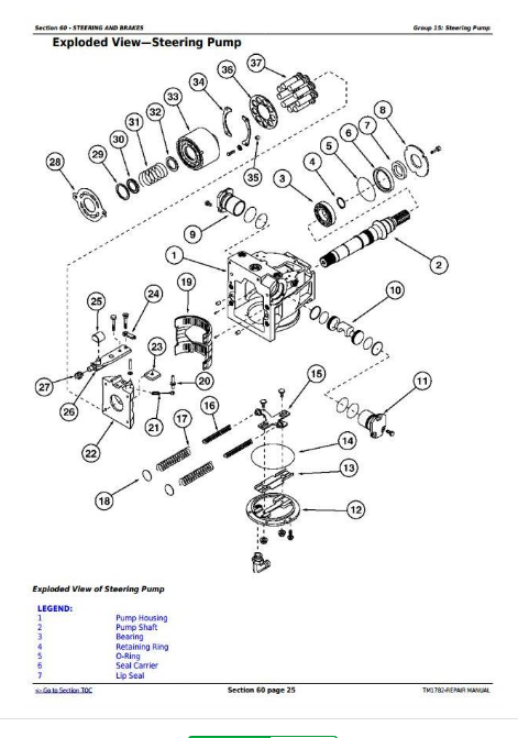
Group 15: Steering Pump
Essential or Recommended Tools
Service Parts Kits
Other Material
Specifications
Remove and Install Steering Pump
Fill Steering Pump Crankcase
Exploded View—Steering Charge Pump and Pump Control
Disassemble, Inspect, and Assemble Steering Charge Pump
Disassemble, Inspect, and Assemble Displacement Control Valve
Exploded View—Steering Pump
Disassemble, Inspect, and Assemble Hydraulic Steering Pump
Group 20: Steering Pump Drive Gearbox
Essential or Recommended Tools
Other Material
Specifications
Remove and Install Steering Pump Drive Gearbox
Disassemble, Inspect, and Assemble Steering Pump Drive Gearbox
Group 25: Steering Motor
Essential or Recommended Tools
Service Parts Kits
Specifications
Remove and Install Steering Motor
Exploded View—Steering Motor
Disassemble, Inspect, and Assemble Steering Motor
Group 30: Brake Valve
Essential or Recommended Tools
Service Parts Kits
Specifications
General Repair Procedures—Brake Valve
Remove and Install Brake Valve
Disassemble, Inspect, and Assemble Brake Valve
Adjust Brake Pedal
Bleed Brakes
Check Manual Brakes
Group 35: Brake Components
Remove and Install Brake Pressure Reducing Valve (9000t S.N. - 900548)
Exploded View—Brake Pressure Reducing Valve Manifold (9000t S.N. - 900548)
Remove and Install Brake Pressure Reducing Valve (9000t S.N. 900549 - )
Exploded View—Brake Pressure Reducing Valve Manifold (9000t S.N. 900549 - )
Group 40: Park Brake—9020T
Essential or Recommended Tools
Specifications
Remove and Install—Park Brake Valve
Exploded View—Park Brake Valve
Manual Park Brake Release 9020T Series w-PST (S. N. -902242)
Manual Park Brake Release 9020T Series w-PST (S. N. 902243-)
Secondary Brake Adjustment—9020T Series w/PST (S. N. 902243-)
Section 70: Hydraulics
Group 05: Hydraulic System Repair
Essential or Recommended Tools
Specifications
General Repair Procedures—Hydraulic Systems
Disconnect Battery Ground Cable
Use Special Wrench
Install Hydraulic Fittings
Drain and Fill Hydraulic Reservoir
Remove and Install Hydraulic Oil Reservoir
Group 10: Hydraulic Pump
Essential or Recommended Tools
Service Parts Kits
Other Material
Specifications
Pump Identification
Remove and Install Hydraulic Pump
Fill Hydraulic Pump Crankcase
Remove and Install Hydraulic Pump Controller—Vickers
Exploded View—Hydraulic Pump Controller—Vickers
Disassemble, Inspect, and Assemble Pump Controller—Vickers
Exploded View—Hydraulic Pump—Vickers
Disassemble and Inspect Hydraulic Pump—Vickers
Replace Pump Shaft Seal—Vickers
Assemble Hydraulic Pump—Vickers
Exploded View—Hydraulic Pump—Sauer
Service Hydraulic Pump Control—Sauer
Disassemble and Inspect Hydraulic Pump—Sauer
Replace Hydraulic Pump Shaft Seal—Sauer
Assemble Hydraulic Pump—Sauer
Group 15: Axle Lubrication Pump
Essential or Recommended Tools
Other Material
Service Parts Kits
Specifications
Remove and Install Axle Lubrication Pump
Exploded View—Axle Lubrication Pump
Disassemble, Inspect, and Assemble Axle Lubrication Pump
Group 20: Filter Housings and Control Valves
Service Parts Kits
Specifications
Remove, Inspect, and Install Hydraulic Filter Housing
Remove, Inspect, and Install Axle Filter Housing
Group 25: Hitch Valve, Selective Control Valves, and Couplers—9000T Series
Essential or Recommended Tools
Service Parts Kits
Specifications
Remove and Install Hitch-SCV Valve Stack
Disassemble and Assemble Hitch-SCV Valve Stack
Disassemble, Inspect, and Assemble Hitch Manifold
Remove, Inspect, and Install Hitch-SCV Solenoids
Disassemble, Inspect, and Assemble Hitch Valve
Test Surge Relief Valve
Disassemble, Inspect, and Assemble Selective Control Valve
Exploded View—Coupler
Repair SCV Couplers
Group 30: Hitch Valve, Selective Control Valves, and Couplers—9020T Series
Service Equipment and Tools
Specifications
Top Cover Identification
Exploded View—Standard End Cover
Exploded View—Deluxe End Cover
Remove and Install Hitch SCV Valve Stack
Disassemble and Assemble Hitch-SCV Valve Stack
Disassemble, Inspect, and Assemble Hitch Manifold
Disassemble, Inspect, and Assemble Hitch Valve
Disassemble, Inspect, and Assemble Selective Control Valve
Repair SCV Couplers
Group 35: Hitch
Essential or Recommended Tools
Other Material
Specifications
Remove and Install Lift Cylinder
Cross-Sectional and Exploded View—90 mm Lift Cylinder
Cross-Sectional and Exploded View—100 mm Lift Cylinder
Disassemble, Inspect, and Assemble Lift Cylinder
Repair Hitch Lift Arm Assembly
Section 80: Miscellaneous
Group 05: Hood and Side Panels
Essential Tools
Remove and Install Hood
Releasing Broken Hood Latch
Adjust Hood
Remove and Install Front Screen
Remove and Install Left Side Panel
Remove and Install Right Side Panel
Adjust Side Panel
Group 10: Platform Step Assembly
Specifications
Remove and Install Platform Step Assembly
Group 15: Frames
Essential or Recommended Tools
Specifications
Remove and Install Front Support
Remove and Install Front Side Frames
Front Side Frame Torque Sequence
Group 20: Hitch Frame and Drawbar
Essential or Recommended Tools
Specifications
Remove and Install Drawbar
Remove and Install Drawbar Support—Standard
Remove and Install Drawbar Support—Wide Swing
Repair Drawbar Roller Carriage—Wide Swing
Remove and Install Drawbar Support—3-Point Hitch
Section 90: Operator Station
Group 00: Cab Removal and Installation
Essential or Recommended Tools
Other Material
Specifications
Remove Cab
Exploded View—Cab Mounts
Install Cab
Repair Cab
Group 05: Heating, Ventilating, and Air Conditioning (HVAC)
Heater Line Routing
Remove HVAC Module
Install HVAC Module
Remove and Install Heater Core
Test Heater Core
Remove, Test, and Install Heater Control Valve—without ClimaTrak is a trademark of Deere & Company
Remove, Test, and Install Heater Control Valve—with CLIMATRAK CLIMATRAK is a trademark of Deere & Company ( S.N - 902000 )
Remove and Install Heater Control Valve With CLIMATRAK CLIMATRAK is a trademark of Deere & Company ( S.N 902001- )
Remove and Install Temperature Control Cable
Adjust Heating/Cooling Control Cable
Group 10: Air Conditioning System
Essential or Recommended Tools
Other Material
Service Parts Kits
Specifications
Hose and Tubing O-Ring Connection Torques
Diagram—Air Conditioning System
Reference Chart—Air Conditioning System Fittings
Leak Test With Dye
Discharge Air Conditioning System
Flushing, Purging, and Evacuating Information
Flush Air Conditioning System
Purge Air Conditioning System
Evacuate Air Conditioning System
Refrigerant Oil Information
Check Compressor Oil Charge
Determine Correct Refrigerant Oil Charge
Add Refrigerant Oil to System
Add Refrigerant Oil to Pressurized System
Charge Air Conditioning System
Remove and Install Compressor
Test Volumetric Efficiency
Test Shaft Seal Leakage
Disassemble and Assemble Compressor Clutch
Check Clutch Hub Clearance
Inspect Compressor Manifold
Inspect Compressor Thermal Bypass Valve
Disassemble, Inspect, and Assemble Compressor
Remove and Install Compressor Relief Valve
Replace Receiver-Dryer
Leak Test Condenser
Remove and Install Air Conditioning Condenser
Leak Test Evaporator
Remove and Install Evaporator
Remove and Install Expansion Valve
Group 15: Air Suspension Seat
Essential or Recommended Tools
Other Material
Remove and Install Seat
Repair Air System
Remove and Install Ride Zone Protector (RZP)
Repair Suspension
Repair Seat Back
Repair Control Knobs
Disassemble and Assemble Adjustable Armrest Support—Style A
Disassemble and Assemble Adjustable Armrest Support—Style B
Group 20: Cab Door and Windshield
Specifications
Door Latch Identification—Version "A" and Version "B"
Repair Cab Door Latch
Cab Door Adjustments
Cab Door Latch Adjustment—Step 1
Door Striker Adjustment—Step 2
Cab Door Latch Adjustment—Step 3
Door Latch Adjustment—Step 4
Replace Windshield Glass
Section 95: Track Frame and Components
Group 05: Tracks
Essential or Recommended Tools
Specifications
Track Tensioning and Detensioning
Remove and Install Track
Group 10: Tension Cylinder and Accumulator
Essential or Recommended Tools
Other Material
Service Parts Kits
Specifications
Remove and Install Track Tension Cylinder
Cross-Sectional and Exploded View—Track Tension Cylinder
Disassemble, Inspect, and Assemble Track Tension Cylinder
Charge Tension Accumulator
Group 15: Track Frame
Essential or Recommended Tools
Other Material
Specifications
Remove and Install Track Frame
Replace Oscillation Bearing
Remove and Install Walking Beam
Replace Walking Beam Pivot Bushing and Isolator Bushing
Repair Pillow Block
Replace Tension Link Pivot Bushings
Repair Front Idler Hubs
Remove, Repair, and Install Two Piece Mid-Roller Assembly
Remove, Repair, and Install One Piece Mid-Roller Assembly
Section 99: Dealer Fabricated Tools
Group 05: Fabricated Tools
Fabricated Tools
DFRW7—Differential Lifting Tool
DFRW20—Compressor Holding Fixture
DFRW63 - DFRW64 - DFRW65 - DFRW66 - DFRW81—Tap-Out Harnesses
DFRW92—Mounting Guide Pins
DFRW103—Yoke Holding Tool Tool may be purchased. Order JDG924.
DFRW113—Hood Supports Tool may be purchased. Order JDG1007.
DFRW116—Hydraulic Reservoir Siphon Tube
DFRW117—Transmission-Hydraulic Flusher
DFRW129—Steering Motor Sensor Gauge
DFRW139—Thermal Expansion Valve Replacement Tool
DFRW140—Engine Support Bracket
DFRW147—Screw Jack
DFRW150—SCV-Hitch Valve Stack Lifting Bracket
![]()