
John Deere 8100, 8200, 8300, 8400, 8110, 8210, 8310, 8410 Tractors Repair Service Manual (TM1575)
Complete Repair Service Technical Manual for John Deere 2WD or MFWD Tractors 8100, 8200, 8300, 8400, 8110, 8210, 8310, and 8410, with all the technical information to maintain, repair, and service like professional mechanics.
John Deere 8100, 8200, 8300, 8400, 8110, 8210, 8310, 8410 Tractors workshop technical manual (repair) includes:
* Numbered table of contents easy to use so that you can find the information you need fast.
* Detailed sub-steps expand on repair procedure information
* Numbered instructions guide you through every repair procedure step by step.
* Notes, cautions and warnings throughout each chapter pinpoint critical information.
* Bold figure number help you quickly match illustrations with instructions.
* Detailed illustrations, drawings and photos guide you through every procedure.
* Enlarged inset helps you identify and examine parts in detail.
tm1575 - 8100, 8200, 8300, 8400, 8110, 8210, 8310, and 8410 Tractors Technical Manual - Repair.pdf
tm1575 - 8100, 8200, 8300, 8400, 8110, 8210, 8310, and 8410 Tractors Technical Manual - Repair.epub
Total Pages: 1,606 pages
File Format: PDF/EPUB/MOBI/AZW (PC/Mac/Android/Kindle/iPhone/iPad; bookmarked, ToC, Searchable, Printable)
Language: English
MAIN SECTIONS
Foreword
Dealer Predelivery Service
General Information
Safety
General Information
Engine
Component Removal and Installation
Engine Repair
Fuel and Cooling Systems
Diesel Fuel System
Air Intake System
Engine Cooling System
Air Conditioning Condenser and Coolers
Electrical
Connectors
Wiring Harness Routings
Charging Circuit
Starting Circuit
Solenoids and Switches
Monitoring Systems and Sensors
Armrest Control
Implement and Accessory Connectors
Convenience and Accessory Components
Power Shift Transmission
Component Removal and Installation
Miscellaneous Repair
8100, 8200, 8300, and 8400 Transmission
8110, 8210, 8310, and 8410 Transmission
Drive Systems
Component Removal and Installation
Rear Differential and Input Quill
Final Drives
Rear PTO
Hydraulic Pump Drive
MFWD Clutch
MFWD Axle-Version “A”
MFWD Axle-Version “B”
Drivelines
Steering and Brakes
Steering Column
Steering Control Assembly
Steering Cylinders
Brake Valve
Brake Components
Trailer Brakes
Hydraulics
Component Removal and Installation
Hydraulic System Repair and Cleanup
Tandem Hydraulic Pump (Steering-Brakes-Charge)
Secondary Hydraulic Pump (Hitch-SCV)
Filter Bypass
Hitch Valve, Selective Control Valves, and Couplers
Hitch
Row Guidance
Miscellaneous
Component Removal and Installation
Front Axle (2-Wheel Drive)
Wagon and Pick-Up Hitch
Operator Station
Component Removal and Installation
Heating, Ventilating and Air Conditioning-(HVAC)
Air Conditioning System
Air Suspension Seat (8000 Series)
Air Suspension Seat (8000 TEN Series)
Armrest
Cab Door and Windshield
Dealer Fabricated Tools
Fabricated Tools
tm1575 - 8100, 8200, 8300, 8400, 8110, 8210, 8310, and 8410 Tractors
Table of Contents
Foreword
Dealer Predelivery Service
Section 10: General Information
Group 05: Safety
Recognize Safety Information
Handle Fluids Safely—Avoid Fires
Prevent Battery Explosions
Prepare for Emergencies
Prevent Acid Burns
Handle Chemical Products Safely
Avoid High-Pressure Fluids
Park Machine Safely
Support Machine Properly
Wear Protective Clothing
Work in Clean Area
Service Machines Safely
Work In Ventilated Area
Illuminate Work Area Safely
Replace Safety Signs
Use Proper Lifting Equipment
Avoid Harmful Asbestos Dust
Avoid Heating Near Pressurized Fluid Lines
Remove Paint Before Welding or Heating
Use Proper Tools
Construct Dealer-Made Tools Safely
Dispose of Waste Properly
Live With Safety
Group 10: General Information
General Specifications
Overall Dimensions
Sealants and Adhesives Cross-Reference Chart
Metric Bolt and Screw Torque Values
Unified Inch Bolt and Screw Torque Values
Glossary of Terms
Section 20: Engine
Group 00: Component Removal and Installation
Essential or Recommended Tools
Specifications
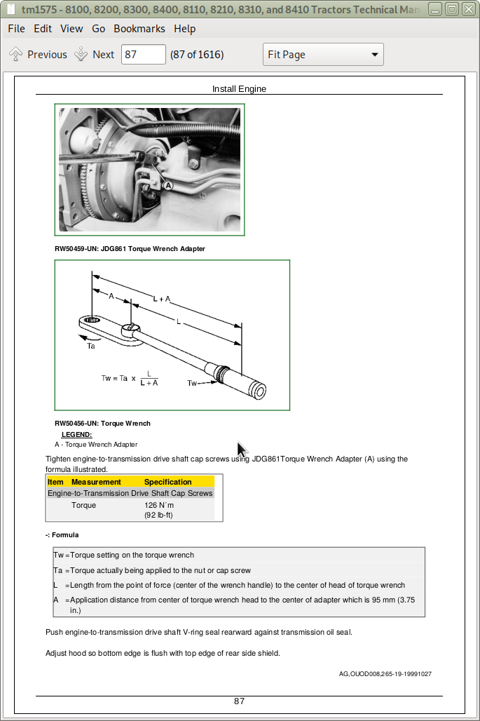
Remove Engine
Install Engine
Remove Front Frame
Install Front Frame
Group 05: Engine Repair
Specifications
Engine Repair—Use CTM42 or CTM86
Access to Front Crankshaft Seal
Access to Rear Crankshaft Seal
Access to Camshaft
Access to Timing Gear Cover
Remove and Install Flywheel Balance Weight—7.6 L Engine
Section 30: Fuel and Cooling Systems
Group 05: Diesel Fuel System
Remove Fuel Tank
Install Fuel Tank
Replace Fuel Filter, Fuel Pump, and Bleed Fuel System
Group 10: Air Intake System
Service Air Intake System
Group 15: Engine Cooling System
Essential or Recommended Tools
Specifications
Test Radiator and Coolant Tank Cap
Remove and Install Radiator/Aftercooler
Auxiliary Drive Belt Routing
Inspect Auxiliary Belt Tensioner
Inspect Fan Belt Tensioner (S. N. 010000— )
Viscous Drive Identification
Remove and Install Viscous Fan Drive
Remove and Disassemble Gear-Driven Fan Drive Assembly
Assemble and Install Gear-Driven Fan Drive Assembly
Remove and Disassemble Belt-Driven Fan Drive Assembly
Assemble and Install Belt-Driven Fan Drive Assembly
Group 20: Air Conditioning Condenser and Coolers
Essential or Recommended Tools
Other Material
Specifications
Remove Fuel-Hydraulic Oil Cooler/Air Conditioning Condenser
Install Fuel-Hydraulic Oil Cooler/Air Conditioning Condenser
Leak Test Fuel-Hydraulic Oil Cooler
Section 40: Electrical
Group 05: Connectors
Essential or Recommended Tools
Other Material
Use Electrical Insulating Compound
Using High-Pressure Washers
Repair Weather Pack Weather Pack is a trademark of Packard Electric Connector
Remove Connector Body from Blade Terminals
Repair (Pull Type) METRI-PACK METRI-PACK is a trademark of Delphi Packard Electric Systems Connectors
Repair (Push Type) METRI-PACK METRI-PACK is a trademark of Delphi Packard Electric Systems Connectors
Repair CPC CPC is a trademark of AMP Incorporated , Large MATE-N-LOC MATE-N-LOC is a trademark of AMP Incorporated and METRIMATE METRIMATE is a trademark of AMP Incorporated Pin Type Connectors
Repair CPC CPC is a trademark of AMP Incorporated Blade Type Connectors
Repair Small MATE-N-LOC MATE-N-LOC is a trademark of AMP Incorporated Socket Connector
Repair Small MATE-N-LOC MATE-N-LOC is a trademark of AMP Incorporated Pin Connector
Repair DEUTSCH DEUTSCH is a trademark of Deutsch Company Connectors
Repair CINCH Connectors
Group 10: Wiring Harness Routings
Ground Point Locations—8000 Series
Ground Point Locations—8000 TEN Series
Main Chassis Harness Routing and Component Identification
Cab Harness Routing—North American
Cab Harness Routing—European
Roof Harness Routing and Component Identification
8000 Series Transmission Harness Routing and Component Identification (Serial No. —019999)
8000 Series Transmission Harness Routing and Component Identification (Serial No. 020000— )
8000 TEN Series Transmission Harness Routing and Component Identification
Starter and Battery Cable Routings
Alternator Power Cable Routing
Wire Number and Color Codes
Load Center Fuses
Load Center Relays and Diodes—North American
Load Center Relays and Diodes—European
Group 15: Charging Circuit
Repair Alternator—Use CTM
Exploded View—Alternator
Replace Alternator
Group 20: Starting Circuit
Essential or Recommended Tools
Specifications
Repair Starter—Use CTM
Remove and Install Starter Motor (Serial No. —009999)
Remove and Install Starter Motor (Serial No. 010000— )
Replace Fusible Link
Replace Starter Circuit Relay
Replace Neutral Start Switch
Group 25: Solenoids and Switches
Essential or Recommended Tools
Other Material
Specifications
General Repair Procedures—Solenoids
Replace Fuel Shut-Off Solenoid
Replace Starting Aid Solenoid
Replace Electro-Hydraulic Shift Valve Solenoids
Replace Park Brake Release Solenoid
Replace PTO Solenoid
Replace MFWD Solenoid
Replace Differential Lock Solenoid
Replace SCV Solenoids
Replace Hitch Valve Solenoids
Replace Engine Oil Pressure Switch
Replace Air Filter Restriction Switch
Replace Transmission Manifold Electrical Switches
Replace Differential Lock Switch
Exploded View—Right Console Controls and Switches
Replace Right Console Switches
Replace Dome Light Switch
Replace Cab Door Light Switch
Replace Beacon Light Switch
Replace Starting Aid and Ignition Switch
Replace Seat Raise/Lower Switch
Replace Operator Presence Seat Switch
Replace Brake Switch
Hand Brake Switch/Harness
Replace Hydraulic Oil Filter Restriction Switch
Replace Hydraulic Clean-Oil Level Switch
Replace External Hitch Raise/Lower Switches
Replace A/C High and Low Pressure Switches
Replace A/C Deicing Switch and Blower Motor Resistor
CLIMATRAK CLIMATRAK is a trademark of Deere & Company Wire Harness and Component Identification
Replace Outlet Duct Temperature Sensor
Replace Cab Temperature Sensor
Replace Fresh Air Temperature Sensor
Replace Evaporator Temperature Sensor
Group 30: Monitoring Systems and Sensors
Essential or Recommended Tools
Other Material
Replace Instrument Control Unit and SCV Setup Panel
Replace Bulbs and Gauges in Instrument Control Unit (ICU)
Replace Bulbs In SCV Set-Up Panel (SUP)
Replace Corner Post Display and Bulbs
Replace Steering Column Module Bulbs
Replace Steering Column Module
Control Units and Component Identification
Replace Control Units
Replace EPROMS EPROMS—Electrically Programmable Read-Only Memory In Control Units
Remove EPROM
Install Replacement EPROM
Replace Engine Coolant Temperature Sensor
Replace Secondary Engine Speed Sensor
Replace Fuel Level Sensor
Replace Fuel Temperature Sensor
Replace Air Intake Temperature Sensor
Replace Foot Throttle Sensor
Replace Wheel Speed Sensor
Replace PTO Speed Sensor (Standard PTO)
Replace PTO Speed Sensor (Optional PTO)
Replace Radar Speed Sensor
Hand Brake Reservoir Level Sensor
Replace Hydraulic Oil Temperature Sensor
Replace Hitch Position Sensor
Replace Draft Sensing Sensor
Adjust Draft Sensing Sensor
Group 35: Armrest Control
Armrest Test Procedures
Replace Armrest Control Assembly
Replace Armrest Control Unit (ACU)
Exploded View—Armrest Control
Replace Armrest Controls
Replace Hitch Control
Exploded View—Transmission Control
Exploded View—Engine Speed Control
Exploded View—SCV Control Lever
Group 40: Implement and Accessory Connectors
Replace Seven-Terminal Outlet Socket
Replace Nine-Pin Terminal Connector (Electro-Hydraulic Depth Control)
Replace Three-Pin Accessory Outlets
Diagnostic/Program, Row Guidance Display, and Front PTO Control Unit Connector
Replace and Adjust Field Lights
Group 45: Convenience and Accessory Components
Specifications
Replace Circulation Blower Motor
Replace Heating, Ventilating and Air Conditioning (HVAC) Pressurizer Blower Motor
Replace Wiper Motors
Replace Windshield Washer Pumps
Test Ground Fault Circuit Interrupter
Replace Hydraulic Charge Pump Auxiliary Heater
Replace Transmission Auxiliary Heater
Replace Seat Air Compressor Motor
Replace Seat Ride Zone Protector
Remove Radio and Speakers
Row Guidance Component Identification
Replace Row Guidance Coupler Position Sensor
Remove and Install Row Guidance Probe Angle Position Sensor and Probe Raise/Lower Motor Relay
Remove Row Guidance Probe Motor
Wagon Tilt Electrical Components
Section 50: Power Shift Transmission
Group 00: Component Removal and Installation
Essential or Recommended Tools
Other Material
Specifications
Remove Transmission
Install Transmission
Remove Scavenge Pump
Install Scavenge Pump
Remove Ground-Driven Pump
Install Ground-Driven Pump
Group 05: Miscellaneous Repair
Essential or Recommended Tools
Other Material
Specifications
Disengage Park Brake
Repair Clutch Pedal
Replace Clutch Cable
Replace Transmission Input Shaft Front Seal
Replace Auxiliary Drive Pulley
Replace Transmission Input Shaft Rear Seal Transmission in Tractor
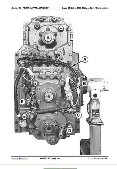
Group 10: 8100, 8200, 8300, and 8400 Transmission
Essential or Recommended Tools
Other Material
Specifications
General Repair Procedures—Power Shift Transmission
Clutch Cover Plate Orientation
Install Transmission In Repair Stand
Cross-Sectional View—Transmission Assembly
Disassemble Transmission
Disassemble and Assemble Switch Isolator Block—(Serial No. —019999)
Exploded View—Manifold Valves
Remove and Install Manifold Valves—(Serial No. —019999)
Remove and Install Manifold Valves—(Serial No. 020000— )
Cleaning Procedures—Manifold, Rear Cover and Valves
Disassemble and Assemble Manifold
Inspect, Clean, Disassemble, and Assemble Electro-Hydraulic Valves—(Serial No. —019999)
Inspect and Clean Electro-Hydraulic Valves—(Serial No. 020000— )
Disassemble and Assemble Manifold
Disassemble and Assemble Transmission Rear Cover
Replace Transmission Rear Cover
Cross-Sectional View—Transmission Input Shaft
Disassemble Input Shaft
Assemble Input Shaft Gear/Clutch Assemblies
Assemble Input Shaft
Cross-Sectional View—Transmission Countershaft
Disassemble Countershaft
Assemble Countershaft Gear/Clutch Assemblies
Assemble Countershaft
Cross-Sectional View— Transmission Output Shaft Assembly
Disassemble Output Shaft Assembly
Disassemble, Inspect, and Assemble Planetary Carrier
Inspect Clutch Disks
Assemble Output Shaft Assembly
Assemble Transmission
Remove Transmission From Repair Stand
Group 15: 8110, 8210, 8310, and 8410 Transmission
Essential or Recommended Tools
Other Material
Specifications
General Repair Procedures—Power Shift Transmission
Clutch Cover Plate Orientation
Install Transmission In Repair Stand
Cross-Sectional View—Transmission Assembly
Disassemble Transmission
Exploded View—Manifold Valves
Remove and Install Manifold Valves
Cleaning Procedures—Manifold, Rear Cover and Valves
Disassemble and Assemble Manifold
Inspect and Clean Electro-Hydraulic Valve
Disassemble and Assemble Manifold
Disassemble and Assemble Transmission Rear Cover
Cross-Sectional View—Transmission Input Shaft
Disassemble Input Shaft
Assemble Input Shaft Gear/Clutch Assemblies
Assemble Input Shaft
Cross-Sectional View—Transmission Countershaft
Disassemble Countershaft
Assemble Countershaft Gear/Clutch Assemblies
Assemble Countershaft
Cross-Sectional View—Transmission Output Shaft Assembly
Disassemble Output Shaft Assembly
Disassemble, Inspect, and Assemble Planetary Carrier
Inspect Clutch Disks
Assemble Output Shaft Assembly
Assemble Transmission
Remove Transmission From Repair Stand
Section 56: Drive Systems
Group 00: Component Removal and Installation
Essential or Recommended Tools
Other Material
Specifications
General Repair Procedures—Sealing Instructions
MFWD Axle Identification—Version "A" and Version "B"
Remove MFWD Clutch
Install MFWD Clutch
Remove MFWD Axle
Install MFWD Axle
Remove Pump Drive Housing
Install Pump Drive Housing
Remove Final Drive
Install Final Drive
Group 05: Rear Differential and Input Quill
Essential or Recommended Tools
Other Material
Specifications
General Repair Procedures—Rear Differential and Input Quill
Remove Differential
Cross-Sectional View—Rear Differential
Disassemble, Inspect, and Assemble Differential
Remove Input Quill Assembly
Cross-Sectional View—Input Quill
Disassemble, Inspect, and Assemble Input Quill
Determine Differential Drive Shaft Cone Point Shim Pack
Assemble and Install Differential Drive Shaft
Install Input Quill Assembly
Install Differential
Side Quill Adjustment Information
Measure End Play and Adjust Differential Preload
Adjust Differential Backlash
Group 10: Final Drives
Essential or Recommended Tools
Specifications
General Repair Procedures—Final Drive
Cross-Sectional View—Final Drive
Disassemble Final Drive
Disassemble, Inspect, and Assemble Planet Pinion Carrier
Remove Axle Housing
Disassemble and Assemble Axle Housing
Disassemble, Inspect, and Assemble Axle Shaft
Install Axle Housing
Adjust Axle Bearings
Group 15: Rear PTO
Essential or Recommended Tools
Other Material
Specifications
General Repair Procedures—PTO Gear Train
Remove and Install PTO Output Housing
Cross-Sectional View—PTO Clutch Assembly
Remove PTO Clutch
Disassemble and Assemble PTO Clutch
Install PTO Clutch
Remove, Inspect, and Install PTO Clutch Valves
Cross-Sectional View—Standard PTO Output Assembly
Disassemble and Assemble Standard PTO Output Housing
Cross-Sectional View—Optional PTO Output Assembly
Disassemble Optional PTO Output Housing Assembly
Assemble Optional PTO Output Housing Assembly
Remove 540/1000 PTO Adapter Assembly
Disassemble and Assemble 540/1000 PTO Adapter Assembly
Install 540/1000 PTO Adapter Assembly
Group 20: Hydraulic Pump Drive
Essential or Recommended Tools
Specifications
General Repair Procedures—Hydraulic Pump Drive
Repair Hydraulic Pump Drive
Cross-Sectional View—Pump Drive Gear Train
Disassemble and Assemble Hydraulic Pump Hypoid Pinion Drive Shaft
Disassemble Hypoid Input Gear Quill Assembly
Assemble Hypoid Input Gear Quill
Set Cone Point—Hypoid Pinion Drive Shaft
Set Cone Point—Hypoid Pinion Drive Gear
Verify Gear Set Backlash
Adjust Hypoid Pinion Drive Shaft End Play
Group 25: MFWD Clutch
Essential or Recommended Tools
Specifications
General Repair Procedures—MFWD Clutch Assembly
Cross-Sectional View—MFWD Clutch Assembly
Disassemble Clutch
Assemble Clutch
Group 30: MFWD Axle—Version “A”
Essential or Recommended Tools
Other Material
Specifications
General Repair Procedures—MFWD Axle
MFWD Axle Identification—Version "A" and Version "B"
Cross-Sectional View—Planetary Carrier, Wheel Hub, and Knuckle Spindle With Early Seal Design
Cross-Sectional View—Planetary Carrier, Wheel Hub, and Knuckle Spindle With Later Seal Design
Remove and Disassemble Planetary Carrier
Replace Wheel Hub Bearings, Bushings, and Seals (Early Seal Design)
Replace Wheel Hub Bearings, Bushings, and Seals (Later Seal Design)
Replace Knuckle Spindle Bushings and Seals (Early Seal Design)
Replace Knuckle Spindle Bushing and Seals (Later Seal Design)
Assemble and Install Planetary Carrier
Remove and Install Axle Housing
Remove Knuckle Spindle Assembly
Disassemble and Assemble Axle Shaft and U-Joint Assembly (Early Seal Design)
Disassemble and Assemble Axle Shaft and U-Joint Assembly (Later Seal Design)
Replace Axle Housing Bushings and Seals (Early Seal Design)
Replace Axle Housing Bushings and Seals (Later Seal Design)
Replace Kingpin Bearing Cups and Seals
Install Axle Shaft and Knuckle Spindle Assembly (Early Seal Design)
Install Axle Shaft and Knuckle Spindle Assembly (Later Seal Design)
Determine Kingpin Shim Pack
Install Differential Housing in Rollover Stand
Remove Differential Assembly
Cross-Sectional View—Differential Assembly
Disassemble Differential
Assemble Differential
Remove and Install Ring Gear
Cross-Sectional View—Input Gear Train
Disassemble Input Gear Train
Determine Differential Drive Shaft Cone Point Shim Pack
Assemble Input Gear Train
Adjust Differential Drive Shaft
Install Differential
Differential Housing Assembly Bearing Adjustment
Adjust Differential Backlash
Disassemble, Inspect, and Assemble Secondary Brakes
Bleed Secondary Hydraulic Brake
Check Secondary Brake Operation
Cross-Sectional View—Oscillating Supports
Repair Front Support
Repair Rear Support
Group 35: MFWD Axle—Version “B”
Essential or Recommended Tools
Other Material
Specifications
General Repair Procedures—MFWD Axle
MFWD Axle Identification—Version "A" and Version "B"
CROSS-SECTIONAL VIEW—PLANETARY CARRIER AND WHEEL HUB
Remove And Disassemble Planetary Carrier And Wheel Hub
Assemble and Install Planetary Carrier and Wheel Hub
Cross-Sectional View—Knuckle Spindle Assembly
Disassemble, Inspect, and Assemble Knuckle Spindle Assembly
Replace Kingpin Bearings and Seals
Remove and Install Planetary Carrier Assembly
Determine Kingpin Shim Pack
Install MFWD Axle In Rollover Stand
Remove Differential
Cross-Sectional View—Differential Housing—North American
Cross-Sectional View—Differential Housing—European
Repair Differential
Assemble Differential
Cross-Sectional View—Input Gear Train
Disassemble Input Gear Train
Determine Pinion Shaft Cone Point Shim Pack
Assemble Input Gear Train
Adjust Pinion Shaft
Disassemble Axle Housing
Check Ring Gear Backlash and Determine Differential Case Bearing Cup Shim Pack
Adjust Backlash
BACKLASH SHIM PACK EXAMPLE AND WORKSHEET
Inspect Oil Dam—European Tractors
Install Differential Case Bearing Cup and Shim Pack
Determine Axle Housing Bearing Cup Shim Pack
Bearing Cup Shim Procedure
PRELOAD SHIM PACK EXAMPLE AND WORKSHEET
Install Axle Housing
Cross-Sectional View—Secondary Brake (European Tractors)
Disassemble, Inspect, and Assemble Secondary Brake
Test Secondary Brake
Bleed Secondary Hydraulic Brake
Check Secondary Brake Operation
Group 40: Drivelines
Specifications
Replace MFWD Drive Shaft
Cross-Sectional View—Mid-Frame Drive Shafts
Repair Mid-Frame Drive Shafts
Section 60: Steering and Brakes
Group 05: Steering Column
Repair Steering Column
Group 10: Steering Control Assembly
Essential or Recommended Tools
Other Material
Service Parts Kits
Specifications
Remove and Install Steering Control Assembly
Exploded View—Steering Control Valve
Disassemble, Inspect, and Assemble Steering Valve
Disassemble, Inspect, and Assemble Priority Valve
Group 15: Steering Cylinders
Other Material
Service Parts Kits
Specifications
Remove and Install Steering Cylinder
Cross-Sectional and Exploded View—Steering Cylinder Two-Wheel Drive
Cross-Sectional and Exploded View—Steering Cylinder MFWD
Group 20: Brake Valve
Service Parts Kits
Specifications
General Repair Procedures—Brake Valve
Remove and Install Brake Valve
Remove and Install Secondary Brake Valve
Disassemble, Inspect, and Assemble Brake Valve
Bleed Brakes
Check Manual Brakes
Group 25: Brake Components
Specifications
Remove, Inspect, and Install Brake Pistons, Plates, and Disks
Group 30: Trailer Brakes
Specifications
Remove, Repair, and Install Hydraulic Trailer Brake Valve
Trailer Brake Line Routings
Bleed Hydraulic Trailer Brake
Repair Air Trailer Brakes
Section 70: Hydraulics
Group 00: Component Removal and Installation
Essential or Recommended Tools
Other Material
Specifications
Remove and Install Tandem Pump Assembly
Remove and Install Secondary Pump
Remove and Install Hitch-SCV Valve Stack
Remove and Install Hitch Frame
Group 05: Hydraulic System Repair and Cleanup
Essential or Recommended Tools
General Repair Procedures—Hydraulic Systems
Install Hydraulic Fittings
Drain Hydraulic System
Fill Hydraulic System
Prelubricate Pump Drive
Conditions Requiring Hydraulic System Cleanup
Hydraulic Cleanup Procedure
Flush the Clean-Oil Reservoir
Clean Priority Valve
Clean Differential Housing
Clean Transmission Housing
Clean Pump Drive Housing
Flush Transmission Manifold
Group 10: Tandem Hydraulic Pump (Steering-Brakes-Charge)
Essential or Recommended Tools
Other Material
Service Parts Kits
Specifications
Exploded View—Tandem Hydraulic Pump
Disassemble, Inspect, and Assemble Tandem Pump
Group 15: Secondary Hydraulic Pump (Hitch-SCV)
Essential or Recommended Tools
Other Material
Service Parts Kits
Specifications
Pump Identification
Exploded View—45 cm3 Secondary Hydraulic Pump
Exploded View—57 cm3 Secondary Hydraulic Pump
Service 45 cm3 Secondary Hydraulic Pump Control
Exploded View—45 cm3 Secondary Pump Controller
Disassemble, Inspect, and Assemble Pump Controller
Service 57 cm3 Secondary Hydraulic Pump Control
Disassemble and Inspect Secondary Hydraulic Pump
Replace Secondary Pump Shaft Seal
Assemble 45 cm3 Secondary Hydraulic Pump
Adjust Yoke Bearing Preload 45 cm3 Hydraulic Pump
Adjust Shaft Bearing Preload 45 cm3 Hydraulic Pump
Assemble 57 cm3 Secondary Hydraulic Pump
Group 20: Filter Bypass
Service Parts Kits
Specifications
Remove, Inspect, and Install Hydraulic Filter Bypass
Group 25: Hitch Valve, Selective Control Valves, and Couplers
Essential or Recommended Tools
Service Parts Kits
Specifications
Disassemble and Assemble Hitch-SCV Valve Stack
Remove, Inspect, and Install Hitch and SCV Solenoids
Disassemble, Inspect, and Assemble Hitch Valve
Test Surge Relief Valve
Disassemble, Inspect, and Assemble Selective Control Valve
Exploded View—Coupler
Repair Couplers
Group 30: Hitch
Essential or Recommended Tools
Other Material
Specifications
Remove and Install Lift Cylinder
Cross-Sectional and Exploded View—Lift Cylinder, 80 and 90 mm
Cross-Sectional and Exploded View—Lift Cylinder, 100 mm
Disassemble, Inspect, and Assemble Lift Cylinder
Replace Rockshaft Bushings—Bolt Version
Replace Rockshaft Bushings—Snap Ring Version
Repair Draft Sensing
Group 35: Row Guidance
Service Parts Kits
Specifications
Remove and Install Probe Module
Repair Row Guidance Cylinder
Exploded View—Row Guidance Cylinder
Section 80: Miscellaneous
Group 00: Component Removal and Installation
Essential or Recommended Tools
Specifications
Remove Front Axle
Install Front Axle
Group 05: Front Axle (2-Wheel Drive)
Essential or Recommended Tools
Specifications
Other Material
Check Pivot Support Bushing Wear
Replace Pivot Support Bushings
Replace Front Axle Pivot Pins
Replace Knee Bushings
Replace Wheel Bearings
Replace Axle Pivot Pins
Group 10: Wagon and Pick-Up Hitch
Specifications
Repair Wagon Hitch
Adjust Wagon Hitch Release
Repair Pick-Up Hitch
Section 90: Operator Station
Group 00: Component Removal and Installation
Essential or Recommended Tools
Remove Cab
Install Cab
Repair Cab
Group 05: Heating, Ventilating and Air Conditioning—(HVAC)
Heater Line Routing
Remove HVAC Module
Install HVAC Module
Remove and Install Heater Core
Remove and Install Heater Control Valve (Without ClimaTrak ClimaTrak is a trademark of Deere & Company )
Remove and Install Heater Control Valve (With ClimaTrak ClimaTrak is a trademark of Deere & Company )
Leak Test Heater Control Valve
Install Heater Control Valve
Remove and Install Control Cable
Adjust Heating/Cooling Controls
Group 10: Air Conditioning System
Essential or Recommended Tools
Other Material
Specifications
Service Parts Kits
Hose and Tubing O-Ring Connection Torques
Diagram—Air Conditioning System
Air Conditioning System Fittings—Reference Chart
Leak Test With Dye
Discharge Air Conditioning System
Remove and Install Compressor
Test Volumetric Efficiency
Test Shaft Seal Leakage
Disassemble and Assemble Compressor Clutch
Check Clutch Hub Clearance
Inspect Compressor Manifold
Disassemble, Inspect, and Assemble Compressor
Remove and Install Compressor Relief Valve
Replace Receiver-Dryer
Remove and Install Expansion Valve
Remove Fuel-Hydraulic Oil Cooler/Air Conditioning Condenser
Leak Test Condenser
Install Fuel-Hydraulic Oil Cooler/Air Conditioning Condenser
Leak Test Evaporator
Remove and Install Evaporator
System Information
Flush Air Conditioning System
Purge Air Conditioning System
Evacuate Air Conditioning System
Refrigerant Oil Information
Check Compressor Oil Charge
Determine Correct Refrigerant Oil Charge
Add Refrigerant Oil to System
Add Refrigerant Oil to Pressurized System
Charge Air Conditioning System
Group 15: Air Suspension Seat (8000 Series)
Other Material
Remove Seat and Swivel Plate From Suspension
Disassemble, Inspect, and Assemble Air Suspension Assembly
Group 20: Air Suspension Seat (8000 TEN Series)
Essential or Recommended Tools
Other Material
Specifications
Remove and Install Seat
Repair Air System
Remove And Install Ride Zone Protector (RZP)
Repair Suspension
Repair Seat Back
Repair Control Knobs
Group 25: Armrest
Remove and Install Armrest
Disassemble and Assemble Armrest Adjustment Assembly
Group 30: Cab Door and Windshield
Specifications
Repair Cab Door Latch
Cab Door Adjustment—Step 1
Cab Door Adjustment—Step 2
Cab Door Adjustment—Step 3
Cab Door Adjustment—Step 4
Cab Door Adjustment—Step 5
Replace Windshield Glass or Seal
Section 99: Dealer Fabricated Tools
Group 05: Fabricated Tools
Fabricated Tools
DF1057—Axle Adjusting Tool
DFRW2—Needle Valve Test Hose Assembly
DFRW4—Axle Wheel Hub Tool
DFRW11—Differential Side Bevel Gear End Play Tool
DFRW12—Wheel Hub and Ring Gear Clamp
DFRW20—Compressor Holding Fixture
DFRW30—Axle Jacking Tool
DFRW60 - DFRW61 - DFRW62—Extension Harnesses
DFRW63 - DFRW64 - DFRW65 - DFRW66 - DFRW81—Tap-Out Harnesses
DFRW89—Transmission Shaft and Clutch Holding Fixture Tool may be purchased. Order JT07203
DFRW90—Transmission Support Plate Tool may be purchased. Order JT07204
DFRW91—Transmission Rear Cover and Manifold Guide Pins Tool may be purchased. Order JT07204
DFRW92—Mounting Guide Pins Tool may be purchased. Order JT07204
DFRW93—Auxiliary Drive Support Bracket Tool may be purchased. Order JT07204
DFRW94—Rear Axle Support Stand Tool may be purchased. Order JT07204
DFRW95—MFWD Clutch Plate Compressor Tool may be purchased. Order JT07204
DFRW96—Rear Axle Lifting Tool Tool may be purchased. Order JT07204
DFRW97—Transmission Countershaft Rotation Screw
DFRW98—Rear Axle Guide Pin Tool may be purchased. Order JT07204
DFRW99—540/1000 PTO Adapter Assembly Bearing Installer
DFRW100—Fan Drive Hub Holding Tool Tool may be purchased. Order JT07204
DFRW101—Fan Drive Bearing Installer
DFRW105—Secondary Brake Bleed Hose
DFRW106—Front Axle Rear Pivot Pin Tool
DFRW107—Front Axle Front Pivot Pin Tool
DFRW111—Flushing Wand
DFRW112—Transmission Flushing Shift Valves
DFRW117—Transmission-Hydraulic Flusher
DFRW132—Differential Side Bevel Gear End Play Tool
DFRW137—Pump Drive Housing Lifting Bracket
DFRW139—Thermal Expansion Valve Replacement Tool
John Deere 8100, 8200, 8300, 8400, 8110, 8210, 8310, 8410 Tractors Repair Service Manual (TM1575)
![]()