
John Deere Tractors 8110, 8210, 8310, 8410 Diagnosis and Tests Service Technical Manual (TM1796)
Complete Diagnosis & Tests Technical Manual with electrical wiring diagrams for John Deere 2WD or MFWD Tractors 8110, 8210, 8310 and 8410, with workshop information to maintain, diagnose, and rebuild like professional mechanics.
John Deere 8110, 8210, 8310 and 8410 Tractors workshop Diagnosis & Tests technical manual includes:
* Numbered table of contents easy to use so that you can find the information you need fast.
* Detailed sub-steps expand on repair procedure information
* Numbered instructions guide you through every repair procedure step by step.
* Troubleshooting and electrical service procedures are combined with detailed wiring diagrams for ease of use.
* Notes, cautions and warnings throughout each chapter pinpoint critical information.
* Bold figure number help you quickly match illustrations with instructions.
* Detailed illustrations, drawings and photos guide you through every procedure.
* Enlarged inset helps you identify and examine parts in detail.
TM1796 - John Deere Tractors 8110, 8210, 8310, 8410 Technical Manual (Diagnosis and Tests).pdf
TM1796 - John Deere Tractors 8110, 8210, 8310, 8410 Technical Manual (Diagnosis and Tests).epub
PRODUCT DETAILS:
Total Pages: 1,117 pages
File Format: PDF/EPUB/MOBI/AZW (PC/Mac/Android/Kindle/iPhone/iPad; bookmarked, ToC, Searchable, Printable)
Language: English
MAIN SECTIONS
Foreword
GENERAL
Safety
SERVICE CODES
ACU Code Diagnostics
AMS Code Diagnostics
CCU Code Diagnostics
ECU Code Diagnostics
HCU Code Diagnostics
ICU Code Diagnostics
JdL Code Diagnostics
PCU Code Diagnostics
SCU Code Diagnostics
SCo Code Diagnostics
SSU Code Diagnostics
SUP Code Diagnostics
OBSERVABLE SYMPTOMS
Axles
Brakes Observable Symptoms
Electrical
Ag Management Solutions (AMS)
Hitch
Heating, Ventilation And Air Conditioning (Standard)
Heating, Ventilation And Air Conditioning - CLIMATRAK™ (ATC)
Operator Station
Power Take-Off
Selective Control Valve
Steering
Transmission
Hydraulics
SYSTEM DIAGNOSIS
Transmission
Steering and Brakes System
Hydraulic System
tm1796 - 8110, 8210, 8310 and 8410 Tractors
Table of Contents
Foreword
Section 210: GENERAL
Group 05: Safety
Recognize Safety Information
Prevent Machine Runaway
Handle Fluids Safely—Avoid Fires
Prevent Battery Explosions
Prepare for Emergencies
Handle Starting Fluid Safely
Prevent Acid Burns
Service Cooling System Safely
Handle Chemical Products Safely
Avoid High-Pressure Fluids
Park Machine Safely
Stay Clear of Rotating Drivelines
Support Machine Properly
Wear Protective Clothing
Service Machines Safely
Work In Ventilated Area
Work in Clean Area
Remove Paint Before Welding or Heating
Avoid Heating Near Pressurized Fluid Lines
Illuminate Work Area Safely
Replace Safety Signs
Use Proper Lifting Equipment
Keep ROPS Installed Properly
Service Tires Safely
Avoid Harmful Asbestos Dust
Protect Against High Pressure Spray
Practice Safe Maintenance
Use Proper Tools
Dispose of Waste Properly
Live With Safety
Section 211: SERVICE CODES
Group ACU: ACU Code Diagnostics
Specifications
ACU 002 - SCV Lever Calibration Failure
ACU 003 - Throttle and Hitch Controls Calibration Failure
ACU 027 - Calibration Not Successful
ACU 028 - Calibration Not Performed
ACU 030 - Engine Throttle Control Failure
ACU 040 - Transmission Shift Lever Failure
ACU 041 - Start in Gear Error
ACU 042 - Transmission Lever Park Position Switch Conflict
ACU 049 - Hitch Raise/Lower Rocker Switch On at Start-up
ACU 053 - Hitch Load/Depth Control Potentiometer
ACU 054 - Hitch Control Lever Potentiometer
ACU 056 - Hitch Raise/Limit Control Potentiometer
ACU 057 - Hitch Rate-of-Drop Control Potentiometer
ACU 070 - IMS Switch Error
ACU 071 - Auto-Shift Resume Switch Error
ACU 110 - SCV No. 1 Control Switch Voltage
ACU 111 - SCV No. 1 Control Switch Status
ACU 120 - SCV No. 2 Control Switch Voltage
ACU 121 - SCV No. 2 Control Switch Status
ACU 130 - SCV No. 3 Control Switch Voltage
ACU 131 - SCV No. 3 Control Switch Status
ACU 140 - SCV No. 4 Control Switch Voltage
ACU 141 - SCV No. 4 Control Switch Status
ACU 150 - SCV No. 5 Control Switch Voltage
ACU 151 - SCV No. 5 Control Switch Status
Group AMS: AMS Code Diagnostics
20 - CAN Bus Problem
21 - CAN Bus Problem
22 - Language Selection Problem
30 - CAN Bus Problem
31 - CAN Bus Problem
33 - Internal Error
40 - Parallel Tracking Problem
41 - Parallel Tracking Problem
44 - Parallel Tracking Problem
45 - Parallel Tracking Problem
46 - Parallel Tracking Problem
47 - Device Address Change
48 - CAN Bus Problem
49 - CAN Bus Problem
50 - Automatic Steering Problem
52 - CAN Bus Problem
53 - CCD Bus Problem
54 - CAN Bus Problem
55 - AutoTrac Problem
60 - Flash Erase Failed
61 - Contour Write Error
100 - KeyCard Problem
110 - Check Wiring (CAN Bus)
111 - Check Wiring (CCD)
126 - AutoTrac disabled
128 - Software not compatible
150 - PC Data Card Problem
151 - PC Data Card Problem
152 - PC Data Card Problem
155 - KeyCard Problem
156 - KeyCard Problem
157 - Invalid Key
158 - KeyCard Problem
200 - CAN Bus Problem
201 - CAN Bus Problem
210 - CAN Bus Problem
211 - CAN Bus Problem
213 - Internal Error
220 - Parallel Tracking Problem
221 - Parallel Tracking Problem
224 - Parallel Tracking Problem
225 - Parallel Tracking Problem
226 - Parallel Tracking Problem
227 - Automatic Steering Problem
230 - Display Address Change
231 - CAN Bus Problem
232 - CAN Bus Problem
233 - Language Selection Problem
234 - CAN Bus Problem
235 - CAN Bus Problem
236 - AutoTrac Problem
280 - Mobile Processor Problem
281 - Mobile Processor Problem
282 - Mobile Processor Problem
301 - STARFIRE STARFIRE is a trademark of Deere & Company Receiver Problem
302 - STARFIRE STARFIRE is a trademark of Deere & Company Receiver Problem
303 - STARFIRE STARFIRE is a trademark of Deere & Company Receiver Problem
304 - STARFIRE STARFIRE is a trademark of Deere & Company Receiver Problem
305 - STARFIRE STARFIRE is a trademark of Deere & Company Receiver Problem
306 - STARFIRE STARFIRE is a trademark of Deere & Company Receiver Problem
308 - RTK Problem
000956.16 - Roll Sensor Out Of Range
002028.12 - No STARFIRE STARFIRE is a trademark of Deere & Company Communication
002146.13 - Terrain Compensation Module Not Calibrated
002146.14 - Temperature Sensor Out Of Range
523309.07 - Yaw Sensor Not Responding
523309.16 - Yaw Sensor Out Of Range
523310.02 - Memory Error
523319.18 - Low Switched Voltage
523342.31 - No STARFIRE STARFIRE is a trademark of Deere & Company Fore/Aft Setting
523441.31 - No STARFIRE STARFIRE is a trademark of Deere & Company Height Setting
523572.31 - Unsafe Shutdown - Parameters Not Stored
523773.03 - STARFIRE STARFIRE is a trademark of Deere & Company CAN Voltage Out Of Range
523773.04 - STARFIRE STARFIRE is a trademark of Deere & Company CAN Voltage Out Of Range
523774.03 - STARFIRE STARFIRE is a trademark of Deere & Company CAN Voltage Out Of Range
523774.04 - STARFIRE STARFIRE is a trademark of Deere & Company CAN Voltage Out Of Range
523792.01 - No Unswitched Voltage
523792.18 - Low Unswitched Voltage
Group CCU: CCU Code Diagnostics
Specifications
CCU 001 - Fuel Level Sensor Circuit
CCU 005 - Engine Oil Pressure Sensor Circuit
CCU 007 - Incorrect ECU For Tractor
CCU 010 - Engine Coolant Temperature High
CCU 011 - Engine Coolant Temperature Very High
CCU 012 - Coolant Temperature Sensor Circuit Open
CCU 013 - Coolant Temperature Sensor Circuit Shorted To Ground
CCU 015 - Hydraulic Oil Temperature High
CCU 016 - Hydraulic Oil Temperature Very High
CCU 017 - Hydraulic Oil Temperature Sensor Circuit Open
CCU 018 - Hydraulic Oil Temperature Sensor Circuit Short To Ground
CCU 019 - Hydraulic Oil Temperature Low
CCU 020 - Engine Oil Pressure Low
CCU 021 - Engine Oil Pressure Low by Switch
CCU 022 - Engine Oil Pressure Sensor Circuit Open
CCU 023 - Engine Speed Sensor Signal Is Missing
CCU 024 - Clean Oil Reservoir Level Switch Circuit Open
CCU 026 - Transmission Oil Pressure Low
CCU 027 - Park Brake Pressure Sensor Circuit Open
CCU 030 - Engine Air Filter Restricted
CCU 045 - System Voltage Low (Above 512 RPM)
CCU 046 - System Voltage Too Low (Above 1500 RPM)
CCU 047 - System Voltage Too High (Above 512 RPM)
CCU 049 - System Voltage Very High (Above 512 RPM)
CCU 050 - Hydraulic Oil Filter Restricted
CCU 056 - CAN Data Bus Error
CCU 062 - Clean Oil Reservoir Low
CCU 063 - Clean Oil Reservoir Low Too Long
CCU 067 - Sensor Power Source (12 VDC) Missing Fuse F14
CCU 068 - PTO Over Speed
CCU 069 - In 4R Or 5R Trying To Engage Rear PTO
CCU 070 - Operator Seat Vacant With PTO On
CCU 071 - PTO Disabled
CCU 072 - PTO Switch Conflict
CCU 073 - PTO Solenoid Circuit Fault
CCU 075 - PTO Speed Low
CCU 076 - PTO Is Not Calibrated
CCU 080 - Differential Lock Switch Stuck On
CCU 081 - Differential Lock Solenoid Circuit Fault With Differential Lock Open
CCU 085 - MFWD Switch Error
CCU 086 - MFWD Circuit Fault
CCU 088 - Intake Manifold Air Temperature High (Less Than 5 Minutes)
CCU 089 - Intake Manifold Air Temperature Too High
CCU 090 - Intake Manifold Air Temperature Sensor Circuit Open
CCU 091 - Intake Manifold Air Temperature Signal Short To Ground
CCU 092 - Intake Manifold Air Temperature High (Greater Than 5 Minutes)
CCU 095 - Hand Throttle Command From ACU Missing
CCU 096 - Foot Throttle Input Voltage Out-Of-Range Low
CCU 097 - Foot Throttle Input Voltage Out-Of-Range High
CCU 098 - Engine Oil Pressure Sensor Failed
CCU 100 - Park Brake Pressure Sensor Failed Or Transmission In Tow Mode With Park Brake Pumped Off
CCU 107 - IMS Hitch Control Unit Not Responding
CCU 108 - Sensor Supply Out Of Range (+5V)
CCU 125 - Turn Signal Switch Conflict
Group ECU: ECU Code Diagnostics
ECU 019 - Engine Coolant Temperature Invalid
ECU 021 - Sensor Supply Voltage High
ECU 022 - Sensor Supply Voltage Low
ECU 026 - Manifold Air Temperature Invalid
ECU 027 - CAN Throttle Invalid
ECU 028 - ECU Error
ECU 031 - Rack Position Error With Engine OFF
ECU 034 - Rack Position Error
ECU 035 - Rack Position Voltage High
ECU 036 - Rack Position Voltage Low
ECU 037 - Fuel Temperature Input Voltage High
ECU 038 - Fuel Temperature Input Voltage Low
ECU 041 - Start Signal Missing
ECU 042 - Engine Overspeed
ECU 044 - Engine Speed Input Noise
ECU 046 - Start Signal Always Active
ECU 048 - Fuel Shut-Off Circuit Fault
ECU 049 - Engine Shutdown Signal Invalid
ECU 052 - Auxiliary Engine Shutdown Switch Active
ECU 053 - Rack Instability
ECU 054 - Intermittent Loss of ECU Power Supply
ECU 055 - CAN Error
ECU 061 - Engine Coolant Level Low
ECU 062 - Engine Coolant Temperature Moderately High
ECU 063 - Engine Coolant Temperature Extremely High
ECU 066 - Manifold Air Temperature Moderately High
ECU 067 - Engine Shutdown
ECU 068 - Fuel Derate
ECU 075 - Rack Actuation Circuit Open
ECU 076 - Rack Actuation Circuit Grounded
ECU 077 - Rack Actuation Circuit Shorted to Power
ECU 081 - Fuel Temperature Moderately High
ECU 083 - Auxiliary Engine Shutdown Switch Active
ECU 085 - Engine Speed Circuit Open
ECU 086 - Engine Speed Input Voltage Low
ECU 087 - Engine Speed Input Voltage High
Group HCU: HCU Code Diagnostics
Specifications
HCU 022 - Battery Voltage Out of Range
HCU 027 - Calibration Not Successful
HCU 028 - Calibration Memory Failure
HCU 029 - Calibration Selected for Less Than 30 Seconds (also recalls “EOC” message)
HCU 041 - Pressure Valve Solenoid Circuit
HCU 042 - Return Valve Solenoid Circuit
HCU 043 - Pressure Valve Solenoid Circuit - Uncalibrated
HCU 044 - Return Valve Solenoid Circuit - Uncalibrated
HCU 045 - Sensor Supply Voltage Out of Range
HCU 049 - Raise/Lower Rocker Switch Circuit
HCU 050 - Internal HCU Failure
HCU 052 - Draft Sensor Circuit
HCU 053 - Load/Depth Control Potentiometer Circuit
HCU 054 - Hitch Control Lever Potentiometer
HCU 055 - Hitch Position Feedback Sensor Circuit
HCU 056 - Raise Limit Control Potentiometer
HCU 057 - Rate-of-Drop Control Potentiometer
HCU 058 - External Raise/Lower Switch Circuit
HCU 060 - CCD Communication Line Failure
HCU 090 - Hitch Raise Disabled Due to Low Oil Level
Group ICU: ICU Code Diagnostics
Specifications
ICU 094 - Vehicle Monitor Touch Switch Stuck
ICU 095 - Not Receiving CCD Data
ICU 096 - Low Air Brake Pressure
ICU 097 - Hand Brake Low Oil Level
ICU 098 - Transmission in Come Home Mode
ICU 099 - ICU Memory Failure
Group JdL: JdL Code Diagnostics
JdL 000629.12 - Control Unit Fault
JdL 000964.13 - Invalid Time/Date
JdL 001542.04 - Control Unit Voltage Low
JdL 298872.31 - Machine Data Configuration Fault 5
JdL 298873.31 - Machine Data Configuration Fault 4
JdL 298874.31 - Machine Data Configuration Fault 3
JdL 298875.31 - Machine Data Configuration Fault 2
JdL 298876.31 - Machine Data Configuration Fault 1
JdL 298877.31 - Modem Fault
JdL 298878.31 - Line Busy
JdL 298879.31 - Cellular Signal Weak or No Service
JdL 298880.31 - Call Unanswered
JdL 298881.18 - GPS Lock Lost
JdL 298882.31 - GPS Lock Fault
JdL 298883.31 - CAN Bus Fault
JdL 298884.31 - CCD Bus Fault
JdL 298885.31 - Control Unit Memory Capacity Exceeded
JdL 298886.31 - Control Unit Power Limit Exceeded
JdL 298887.31 - Control Unit Configuration and Machine PIN Conflict
JdL 299613.31 - Data Download Fault
JdL 299614.31 - Data Upload Fault
JdL 299615.31 - Cellular Bit Error Rate too High
JdL 299616.31 - Call Disconnected
JdL 299617.31 - Data Exchange Fault
JdL 299618.31 - Communications Service Identification Module Fault
JdL 299619.31 - Cellular Personal Identification Number Blocked
JdL 299620.31 - GPS Antenna/Cable Fault
JdL 299630.12 - Calibration Memory Fault
JdL 299639.14 - JdL CAN Error Limit Exceeded
JdL 299841.12 - GPS Fault
JdL 299841.31 - GPS Not Available
Group PCU: PCU Code Diagnostics
Specifications
PCU 005 - Fuel Flow Signal From ECU Missing
PCU 006 - Downshifting with Engine Overspeed
PCU 008 - No Load Fuel Flow (NLFF) Not Calibrated
PCU 011 - Engine Speed Too Low for Wheel Speed
PCU 012 - Shifting Above 14F with Hydraulic Oil Temperature At Or Below 0°C (32°F)
PCU 013 - Engaging Park But Park Brake Pressure High
PCU 014 - Shifting Above 13F or 3R with Clutch Engaged Circuit Open
PCU 015 - Clutch Engage Sensor Circuit Open
PCU 016 - Clutch Engage Sensor Open for More Than 5 Minutes
PCU 017 - Operator Seat Vacant with Transmission in NEUTRAL
PCU 018 - CC or DC Clutches Slipping Too Long
PCU 019 - Park Brake Pressure Sensor Failed Open
PCU 020 - Seat Switch Failed Closed
PCU 021 - Clutch Engaged Switch Failed Closed
PCU 022 - Excessive Load on Engine in 4R or 5R
PCU 024 - Park Brake Previously Failed-May Not Hold
PCU 025 - Park Brake Engaged But Tractor Moving
PCU 026 - Shifted to Park While Tractor was Moving Too Fast
PCU 027 - Transmission Not Calibrated
PCU 028 - AB Or BC Clutch Slipping
PCU 029 - Low Park Brake Pressure
PCU 030 - Clutch Engage and Clutch Disengage Circuit Conflict
PCU 031 - Clutch Slipping-Damage May Occur
PCU 032 - C1 Valve Circuit Fault
PCU 033 - C2 Valve Circuit Fault
PCU 034 - C3 Valve Circuit Fault
PCU 035 - C4 Valve Circuit Fault
PCU 036 - AB Valve Circuit Fault
PCU 037 - BC Valve Circuit Fault
PCU 038 - PCU Fault
PCU 039 - Reverse Enable Circuit Fault
PCU 040 - Forward Enable Circuit Fault
PCU 041 - Forward and Reverse Enable Circuit Conflict (Both Enabled)
PCU 042 - Reverse Commanded/Forward Enabled
PCU 043 - Forward Commanded/Reverse Enabled
PCU 044 - Forward or Reverse Commanded/Transmission NOT Enabled
PCU 045 - Neutral or Park Commanded/Transmission Is Enabled
PCU 046 - Neutral or Park Commanded/Forward or Reverse Enabled
PCU 048 - System Voltage Low
PCU 049 - Auto Purge Complete
PCU 050 - No Tractor Motion with Engine OFF
PCU 051 - No Tractor Motion with Engine Running
PCU 053 - CC Valve Circuit Fault
PCU 054 - DC Valve Circuit Fault
PCU 055 - CR Valve Circuit Fault
PCU 056 - Park Brake Valve Circuit Fault
PCU 058 - Tractor Moved During Calibration
PCU 060 - Tractor Startup in Gear
PCU 062 - Operator Seat Vacant when Shifted into Gear
PCU 063 - PCU Shift Table Fault
PCU 065 - PCU Self test Fault
PCU 067 - Transmission Enable Circuit Fault
PCU 069 - Calibration Failure (Calibration Value Out of Spec)
PCU 070 - Missing Gear Command from ACU
PCU 072 - PCU RAM Memory Fault
PCU 073 - PCU EEPROM Failure
PCU 074 - PCU Software Failure
PCU 075 - PCU Oscillator Failure
PCU 076 - Rear PTO Not Calibrated
Group SCU: SCU Code Diagnostics
Specifications
SCU 022 - Battery Voltage Out of Range—Fuse F5
SCU 023 - Battery Voltage Out of Range—Fuse F6
SCU 027 - Calibration Not Successful
SCU 028 - Calibration Memory Failure
SCU 029 - Calibration Selected for Less Than 30 Seconds (also recalls “EOC” message)
SCU 048 - Remote Position Feedback Sensor (TSDC)
SCU 060 - CCD Communication Line Failure
SCU 090 - SCV Function Disabled Due To Low Oil Level
SCU 098 - Option Pin Configuration Invalid at Start-Up
SCU 099 - TSDC Option Connector Installed or Removed with Key Switch ON
SCU 100 - Operator Seat Vacant With SCV in Detented Flow and Transmission in Neutral
SCU 101 - Remote Sensor 1 Voltage Fault
SCU 102 - Remote Sensor 2 Voltage Fault
SCU 110 - SCV No. 1 Control Circuit
SCU 111 - SCV No. 1 Extend Valve Circuit
SCU 112 - SCV No. 1 Retract Valve Circuit
SCU 113 - SCV No. 1 Extend Valve Circuit (During CAL)
SCU 114 - SCV No. 1 Retract Valve Circuit (During CAL)
SCU 120 - SCV No. 2 Control Circuit
SCU 121 - SCV No. 2 Extend Valve Circuit
SCU 122 - SCV No. 2 Retract Valve Circuit
SCU 123 - SCV No. 2 Extend Valve Circuit (During CAL)
SCU 124 - SCV No. 2 Retract Valve Circuit (During CAL)
SCU 130 - SCV No. 3 Control Circuit
SCU 131 - SCV No. 3 Extend Valve Circuit
SCU 132 - SCV No. 3 Retract Valve Circuit
SCU 133 - SCV No. 3 Extend Valve Circuit (During CAL)
SCU 134 - SCV No. 3 Retract Valve Circuit (During CAL)
Group SCo: SCo Code Diagnostics
Specifications
SCo 022 - Battery Voltage Out of Range
SCo 027 - Calibration Not Successful
SCo 028 - Calibration Memory Failure
SCo 029 - Calibration Selected for Less Than 30 Seconds (also recalls “EOC” message)
SCo 060 - CCD Communication Line Failure
SCo 090 - SCV Function Disabled Due to Low Oil Level
SCo 098 - Option Pin Configuration Invalid at Start-Up
SCo 099 - TSDC Option Connector Installed or Removed with Key Switch ON
SCo 100 - Operator Seat Vacant With SCV in Detented Flow and Transmission in Neutral
SCo 140 - SCV No. 4 Control Circuit
SCo 141 - SCV No. 4 Extend Valve Circuit
SCo 142 - SCV No. 4 Retract Valve Circuit
SCo 143 - SCV No. 4 Extend Valve Circuit (During CAL)
SCo 144 - SCV No. 4 Retract Valve Circuit (During CAL)
SCo 150 - SCV No. 5 Control Circuit
SCo 151 - SCV No. 5 Extend Valve Circuit
SCo 152 - SCV No. 5 Retract Valve Circuit
SCo 153 - SCV No. 5 Extend Valve Circuit (During CAL)
SCo 154 - SCV No. 5 Retract Valve Circuit (During CAL)
Group SSU: SSU Code Diagnostics
Specifications
SSU 001 - Control Unit Fault
SSU 002 - Control Unit Fault
SSU 004 - Vehicle Mismatch
SSU 008 - Activation Code Invalid
SSU 020 - SSU Not Calibrated
SSU 021 - Steering Valve Supply Voltage Low
SSU 029 - SSU EOL Data Fault
SSU 030 - SSU Supply Voltage Fault
SSU 031 - Sensor Supply Voltage Fault
SSU 041 - Steering Wheel Position Sensor 1 Supply Voltage Fault
SSU 042 - Steering Wheel Position Sensor 1 Current Fault
SSU 043 - Steering Wheel Position Sensor 1 Signal Fault
SSU 045 - Steering Wheel Position Sensor 1 Signal Mismatch
SSU 051 - Steering Wheel Position Sensor 2 Supply Voltage Fault
SSU 052 - Steering Wheel Position Sensor 2 Current Fault
SSU 053 - Steering Wheel Position Sensor 2 Signal Fault
SSU 055 - Steering Wheel Position Sensor 2 Signal Mismatch
SSU 065 - Steering Movement Occurred w/No Steering Wheel Signal Detected
SSU 066 - Steering Input Device Calibration Fault
SSU 100 - Operator Presence Switch Circuit Fault
SSU 101 - Operator Presence Switch Circuit Fault
SSU 111 - Steering Valve Fault
SSU 153 - Steering Angle Sensor Calibration Fault
SSU 156 - Steering Angle Sensor Circuit Fault
SSU 158 - Steering Angle Sensor Low or No Motion
SSU 159 - Steering Direction Signal Conflict
SSU 182 - Steering System Fault
SSU 196 - Steering Valve Deadband Calibration Fault
SSU 197 - Steering Valve Command Low
SSU 198 - Steering Valve Command High
SSU 199 - Steering System Output Fault
SSU 201 - Wheel Speed Signal Missing
SSU 203 - Transmission Signal Missing
SSU 205 - Hydraulic Oil Temperature Signal Missing
SSU 206 - Resume Switch Signal Missing
SSU 208 - GREENSTAR GREENSTAR is a trademark of Deere & Company Display Message Fault w/AutoTrac Active or Enabled
SSU 209 - TCM Message Missing
Group SUP: SUP Code Diagnostics
SUP 010 - Communication From SCU Missing
SUP 011 - Communication From SCo Missing
SUP 020 - Setup Panel Controller Failure
Section 212: OBSERVABLE SYMPTOMS
Group 05: Axles
Specifications
Axle Will Not Transmit Power
MFWD Axle Disengages
Differential Lock Won't Engage / Disengage
Group 10: Brakes Observable Symptoms
Brake System Diagnosis
Group 15: Electrical
Specifications
Vehicle Horn Malfunctions
Start Motor Will Not Crank
Convenience Outlet Problem
Charging System Problem
Radar Diagnostics
Seven Pin Outlet Malfunction—(N.A.)
Seven Pin Outlet Malfunction—(European)
Hazard Lights Malfunction (NA)
Hazard Lights Malfunction (EUR)
Dome Light Malfunction
Roof Beacon Light Malfunction
Lighting System Malfunction (NA)
Lighting System Malfunction (EUR)
Touchset Depth Control Does Not Function
Turn Signal Lights Malfunction (NA)
Turn Signal Lights Malfunction (EUR)
Group 16: Ag Management Solutions (AMS)
GREENSTAR GREENSTAR Is A Trademark Of Deere & Company System Problem
Loss Of Power At Implement Breakaway Connector
JDLINK JDLINK Is A Trademark Of Deere & Company System Problem
AUTOTRAC System Problem
GREENSTAR™FIELD DOC FIELD DOC Is A Trademark Of Deere & Company Diagnostics
Group 20: Hitch
Specifications
Hitch Won't Raise And / Or Lower
Hitch Raise / Lower Speed Incorrect
Hitch Cycles Up And Down
Group 25: Heating, Ventilation And Air Conditioning (Standard)
Specifications
Air Conditioning Not Cooling Or Cooling Inadequate (Standard)
Heating Inadequate (Standard)
Low Or No Air Flow From Air Ducts (Standard)
Group 26: Heating, Ventilation And Air Conditioning - CLIMATRAK™ (ATC)
Specifications
CLIMATRAK CLIMATRAK is a trademark of Deere & Company (ATC) Trouble Light Flashing
Diagnostic Trouble Lamp Does Not Light, CLIMATRAK CLIMATRAK is a trademark of Deere & Company (ATC)
Compressor Clutch Does Not Engage (No Cooling), CLIMATRAK CLIMATRAK is a trademark of Deere & Company (ATC)
Circulation Blower Inoperative Or Slow, CLIMATRAK CLIMATRAK is a trademark of Deere & Company (ATC)
Pressurizer Motor Inoperative Or Slow, CLIMATRAK CLIMATRAK is a trademark of Deere & Company (ATC)
Group 30: Operator Station
Dust In Cab
Operator Seat Problem
Warning Horn Does Not Operate
Turn Signals Do Not Work
Display Units Not Operational
Windshield Wiper / Washer Malfunctioning
Power Mirror Malfunction
Group 40: Power Take-Off
Specifications
PTO Slips Under Load
PTO Engages Aggressively
PTO Will Not Stop Turning
Group 45: Selective Control Valve
Specifications
Hose Ejects From SCV Coupler
Implement Settles
Pressure Does Not Build in Top SCV or Power Beyond
SCV(S) Does Not Work
Group 50: Steering
Specifications
AutoTrac System - Accuracy Unacceptable
Loss Of Power Steering And Brakes
Loss Of Power Steering (Brakes Are Normal)
Loss Of Manual Steering Or Secondary Steering Is Poor With Tractor Moving
Steering Capacity Low Or Stalls Under Load
Front Wheels Wander Or Drift
Intermittent Drag When Turning Steering Wheel
Steering Is Slow, Sluggish, Or Hard To Turn (Tractor In Motion)
Group 55: Transmission
Specifications
Tractor Won't Move
Transmission Calibration Fails And "F" Error Message is Displayed After Repair and Following Reassembly
Transmission Does Not Shift Correctly
Tractor Creeps In Neutral
Group 70: Hydraulics
Optional SCV Software Troubleshooting
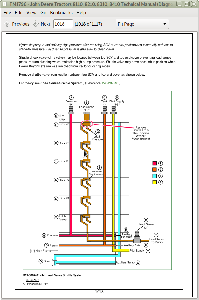
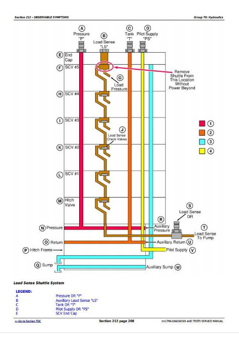
Pump Pressure Slowly Returns to Stand-by after SCV Returned to Neutral
Section 213: SYSTEM DIAGNOSIS
Group 50: Transmission
Specifications
Transmission System Diagnosis
Group 60: Steering and Brakes System
Specifications
Steering / Brake System Diagnosis
AutoTrac Steering System Diagnosis
Group 70: Hydraulic System
Specifications
Hydraulic System Diagnosis
John Deere Tractors 8110, 8210, 8310, 8410 Diagnosis and Tests Service Technical Manual (TM1796)
![]()