
John Deere PowerTech 4.5L & 6.8L Diesel Engines Level 12 Electronic Fuel System Component Technical Manual (CTM331)
Complete Component Technical Manual with electrical wiring diagrams for John Deere PowerTech 4.5L & 6.8L Diesel Engines Level 12 Electronic Fuel System with Stanadyne DE10 Pump, with all the shop information to maintain, diagnose, repair, and rebuild like professional mechanics.
John Deere PowerTech 4.5L & 6.8L Diesel Engines Level 12 Electronic Fuel System with Stanadyne DE10 Pump workshop CTM includes:
* Numbered table of contents easy to use so that you can find the information you need fast.
* Detailed sub-steps expand on repair procedure information
* Numbered instructions guide you through every repair procedure step by step.
* Troubleshooting and electrical service procedures are combined with detailed wiring diagrams for ease of use.
* Notes, cautions and warnings throughout each chapter pinpoint critical information.
* Bold figure number help you quickly match illustrations with instructions.
* Detailed illustrations, drawings and photos guide you through every procedure.
* Enlarged inset helps you identify and examine parts in detail.
ctm331 - PowerTech 4.5L & 6.8L Diesel EnginesLevel 12 Electronic Fuel System With Stanadyne DE10 Pump - (Worldwide Edition) Technical Manual.pdf
CTM331 (09APR02) (ENGLISH) - John Deere PowerTech 4.5L & 6.8L Diesel Engines - John Deere Level 12 Electronic Fuel System with Stanadyne DE10 Pump Technical Manual.pdf
CTM331 (15FEB11) (ENGLISH) - John Deere PowerTech 4.5L & 6.8L Diesel Engines - John Deere Level 12 Electronic Fuel System with Stanadyne DE10 Pump Technical Manual.pdf
ctm332 - Motores diésel PowerTech™ de 4.5 l y 6.8 l Sistema de combustible electrónico Nivel 12 con bomba Stanadyne DE10 -: (Edición mundial).pdf
ctm333 - Moteurs diesel PowerTech™ 4,5 l et 6,8 l Circuit d'alimentation électronique, niveau 12, avec pompe Stanadyne DE10 -: (Édition mondiale).pdf
ctm334 - PowerTech™ 4,5-l- und 6,8-l-Dieselmotoren Elektronisches Kraftstoffsystem der Stufe 12 mit Stanadyne-Pumpe DE10 -: (Weltweite Ausgabe).pdf
ctm335 - Motori diesel PowerTech™ da 4,5 e 6,8 l Sistema di iniezione elettronica Livello 12 con pompa Stanadyne DE10 -: (Edizione universale).pdf
ctm339 - Motores Diesel PowerTech™ 4.5L e 6.8L Sistema Eletrônico de Combustível Nível 12 com Bomba Stanadyne DE10 -: (Edição Mundial).pdf
ctm614 - PowerTech™ 4.5 升和 6.8 升柴油发动机 配备 Stanadyne DE10 喷油泵 12 级电子燃油系统 -: (世界通用机型).pdf
ctm618 - Дизельные двигатели PowerTech™ объемом 4,5 л и 6,8 л Электронная топливная система уровня 12 с насосом Stanadyne DE10 -: (Исполнение для всех стран).pdf
Total Pages: 556 pages
File Format: PDF/EPUB/MOBI/AZW (PC/Mac/Android/Kindle/iPhone/iPad; bookmarked, ToC, Searchable, Printable)
Language: English Spanish Russian Chinese Portuguese Italian French German
MAIN SECTIONS
Section 01—General Information
Group 000—Safety
Group 001—Engine Identification
Group 002—Fuels
Section 02—Repair and Adjustments
Group 090—Electronic Fuel System Repair and Adjustments
Group 110—Electrical Engine Control Repair and Adjustment
Section 03—Theory of Operation
Group 130—Electronic Fuel System Operation
Group 140—Electronic Control System Operation
Section 04—Diagnostics
Group 150—Observable Diagnostics and Tests
Group 160—Trouble Code Diagnostics and Tests
Section 05—Tools and Other Materials
Group 170—Electronic Fuel/Control System Repair Tools and Other Materials
Group 180—Diagnostic Service Tools
Section 06—Specifications
Group 200—Repair Specifications
Group 210—Diagnostic Specifications
...
TABLE OF CONTENTS......1
Section 01: General Information......16
Group 000: Safety......16
Handle Fluids Safely—Avoid Fires......18
Handle Starting Fluid Safely......19
Prepare for Emergencies......20
Avoid High-Pressure Fluids......21
Avoid Static Electricity Risk When Refueling......22
Wear Protective Clothing......24
Service Machines Safely......25
Work In Ventilated Area......26
Work in Clean Area......27
Remove Paint Before Welding or Heating......28
Avoid Heating Near Pressurized Fluid Lines......29
Illuminate Work Area Safely......30
Construct Dealer-Made Tools Safely......31
Practice Safe Maintenance......32
Use Proper Tools......34
Decommissioning — Proper Recycling and Disposal of Fluids and Components......35
Live With Safety......36
Group 001: Engine Identification......16
Engine Model Designation......39
Engine Serial Number Plate Information......41
OEM Engine Option Code Label......44
Information Relative to Emissions Regulations......45
Group 002: Fuels......16
Lubricants and Coolant......47
Diesel Fuel......48
Lubricity of Diesel Fuel......50
Testing Diesel Fuel......51
BioDiesel Fuel......52
Diesel Fuel Additive Products......54
Section 02: Repair and Adjustments......55
Group 090: Electronic Fuel System Repair and Adjustments......55
Fuel System — General Information......58
Relieve Fuel System Pressure......59
Remove and Install Final Fuel Filter/Water Bowl and/or Pre-Filter/Water Bowl Base......60
Fuel Pre-Filter/Water Bowl Assembly (Optional)......62
Final Fuel Filter Assembly......64
Replace Final Fuel Filter/Water Bowl and Pre-Filter/Water Bowl......66
Remove Fuel Supply Pump......68
Install Fuel Supply Pump......70
Injection Pump Static Timing......71
Remove Injection Pump......72
Fuel Injection Pump — Repair......75
Inspect Injection Pump Drive Gear ID and Shaft OD......79
Install Injection Pump......80
Remove Fuel Injection Nozzles......85
Clean Fuel Injection Nozzle Bore......87
Clean Fuel Injection Nozzles......88
Fuel Injection Nozzle Test......89
Disassemble Fuel Injection Nozzles......92
Adjust Fuel Injection Nozzle......93
Install Seals on Fuel Injection Nozzle......95
Install Fuel Injection Nozzles......96
Group 110: Electrical Engine Control Repair and Adjustment......55
Engine Control Unit (ECU)......165
Remove and Install Engine Coolant Temperature Sensor......100
Remove and Install Loss of Coolant Temperature Sensor......101
Replace Crankshaft Position Sensor......102
Remove and Install Oil Pressure Sensor......103
Remove and Install Manifold Air Temperature Sensor......104
Remove and Install Fuel Temperature Sensor......105
Remove and Install Fuel Heater......106
Connectors......107
Use Electrical Insulating Compound......108
Using High-Pressure Washer......109
Repair Weather Pack Connector......110
Remove Blade Terminals from Connector Body......113
Repair (Pull Type) Metri-Pack Connectors......114
Repair (Push Type) Metri-Pack Connectors......117
Repair DEUTSCH Connectors......120
Repair AMP Connector......123
Section 03: Theory of Operation......126
Group 130: Electronic Fuel System Operation......129
About this Group......128
Fuel System Operation......129
Fuel Supply Pump Operation......131
Final Fuel Filter Operation......133
Fuel Injection Pump Operation......135
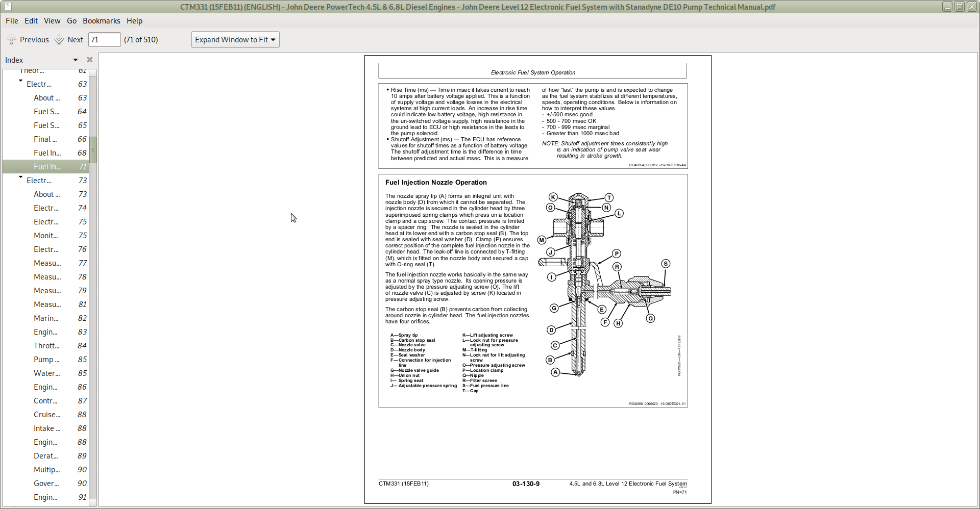
Fuel Injection Nozzle Operation......139
Group 140: Electronic Control System Operation......145
About This Group......142
Electronic Control System Terminology......143
Electronic Control System Operation......145
Monitoring Engine Parameters......146
Electronic Control System Overview......147
Measuring Temperature......149
Measuring Pressure......152
Measuring Throttle Position......153
Measuring Engine Speed......156
Marine Throttle Control Options......157
Engine Synchronization Throttle Control......159
Throttle Control Location Transfer......161
Pump Solenoid......163
Water in Fuel (WIF) Sensor......164
Engine Control Unit (ECU)......165
Controller Area Network (CAN)......167
Cruise Control Operation......168
Intake Air Heater Operation......169
Engine Protection......170
Derate Programs......171
Multiple Torque Curve Selection......172
Governor Droop Mode Selection......173
Engine Control Unit (ECU) Self-Diagnosis......174
Section 04: Diagnostics......176
Group 150: Observable Diagnostics and Tests......176
About This Group of the Manual......186
E1 - Engine Cranks/Won't Start......176
E2 - Engine Misfires/Runs Irregularly......176
E3 - Engine Does Not Develop Full Power......176
E4 - Engine Emits Excessive White Exhaust Smoke......176
E5 - Engine Emits Excessive Black Or Gray Smoke......176
E6 - Engine Will Not Crank......176
E7 - Engine Idles Poorly......176
E8 - Abnormal Engine Noise......176
E9 - Analog Throttle (B) Does Not Respond......176
F1 - Fuel Supply System Check......176
F2 - Excessive Fuel Consumption......176
F3 - Fuel in Oil......176
F5 - Fuel Injection Nozzle Check......176
F6 - Excessive Fuel Filter Replacement......230
D1 - ECU Does Not Communicate with the DST or SERVICE ADVISOR......233
D1 - ECU Does Not Communicate With the DST or Service ADVISOR™......176
D2 - Diagnostic Gauge (Earlier Model) Does Not Communicate With ECU......240
D2 - Diagnostic Gauge (Earlier Model) Does Not Communicate With ECU......240
D3 - Diagnostic Gauge (Later Model) Does Not Communicate With ECU......247
D3 - Diagnostic Gauge (Later Model) Does Not Communicate With ECU......247
A1 - Intake Air Heater Check......253
A1 - Intake Air Heater Check - Continued......254
A1 - Intake Air Heater Check......253
Check Fuel Supply Quality......260
Test for Fuel Drain Back......262
Test for Air in Fuel......263
Check Fuel Supply Pressure......264
Bench Test Fuel Supply Pump......265
Bleed the Fuel System......267
Test for Cylinder Misfire (Engine Running)......270
Load Profile Information Test — Instructions......271
Group 160: Trouble Code Diagnostics and Tests......177
About this Group of the Manual......276
Electrical Concepts......277
Using a Digital Multimeter......278
Electrical Circuit Malfunctions......279
Troubleshooting Circuit Malfunctions......282
Connecting to Diagnostic Scan Tool (DST) or Service ADVISOR......286
Viewing Active DTCs on Diagnostic Gauge (Earlier Model)......291
Viewing Stored DTCs on Diagnostic Gauge (Earlier Model)......292
Clearing Stored DTCs on Diagnostic Gauge (Earlier Model)......293
Engine Configuration Parameters on Diagnostic Gauge (Earlier Model)......295
Viewing Active DTCs on Diagnostic Gauge (Later Model)......298
Viewing Stored DTCs on Diagnostic Gauge (Later Model)......301
Clearing Stored DTCs on Diagnostic Gauge (Later Model)......303
Blinking DTCs......304
Data Parameter Description......305
Engine Test Instructions - Excavator Torque Curve Change Test......309
Engine Control Unit (ECU) — Level Identification......310
Engine Control Unit (ECU) — Donating this Engine’s ECU to be Used Elsewhere......311
Engine Control Unit (ECU) — Replacing Current ECU with Another ECU......315
Engine Control Unit (ECU) — Replacing Current ECU with Another ECU — Cannot Communicate with Current ECU......317
Engine Control Unit (ECU) — Reprogramming Current ECU......319
Engine Control Unit (ECU) — Reprogramming Instructions......320
Software and Hardware Verification......322
Diagnostic Trouble Codes (DTCs)......325
Listing of Diagnostic Trouble Codes (DTCs) on ECU......326
Diagnostic Procedure......332
Intermittent Fault Diagnostics......333
T1 - Multi-state Throttle Input High......334
T1 - Multi-state Throttle Input High......334
T2 - Multi-state Throttle Input Low......338
T2 - Multi-state Throttle Input Low......338
T3 - Analog Throttle (A) Input High......342
T3 - Analog Throttle (A) Input High......342
T4 - Analog Throttle (A) Input Low......347
T4 - Analog Throttle (A) Input Low......347
T5 - Analog Throttle (B) Input High......352
T5 - Analog Throttle (B) Input High......352
T6 - Analog Throttle (B) Input Low......357
T6 - Analog Throttle (B) Input Low......357
T7 - CAN Throttle Invalid......362
T7 - CAN Throttle Invalid......362
T11 - Excavator Throttle Reference Voltage High......366
T11 - Excavator Throttle Reference Voltage High......366
T12 - Excavator Throttle Reference Voltage Low......370
T12 - Excavator Throttle Reference Voltage Low......370
T13 - Excavator Throttle Ground Voltage High......374
T13 - Excavator Throttle Ground Voltage High......374
T14 - Excavator Throttle Ground Voltage Low......378
T14 - Excavator Throttle Ground Voltage Low......378
T15 - Excavator Throttle Input Voltage High......382
T15 - Excavator Throttle Input Voltage High......382
T16 - Excavator Throttle Input Voltage Low......386
T16 - Excavator Throttle Input Voltage Low......386
T17 - Analog Throttle (C) Input High......390
T17 - Analog Throttle (C) Input High......390
T18 - Analog Throttle (C) Input Low......394
T18 - Analog Throttle (C) Input Low......394
T19 - Throttle Not Calibrated Properly......178
T20 - Throttle Input Voltage Below Lower Calibration Limit......178
T21 - Throttle Calibration Aborted......178
T22 - Analog Throttle (A) Input Voltage Out of Range......178
T23 - Multi-state Throttle Input Voltage Out of Range......178
000028.03 - Throttle Voltage High......178
000028.04 - Throttle Voltage Low......179
000029.03 - Throttle Voltage High......179
000029.04 - Throttle Voltage Low......179
000029.14 - Throttle Voltage Out of Range......179
000084.31 — Vehicle Speed Mismatch......179
000084.31 - Vehicle Speed Mismatch......179
000091.03 - Throttle Voltage High......179
000091.04 - Throttle Voltage Low......179
000091.07 - Throttle Calibration Invalid......179
000091.09 - Throttle CAN message Missing......179
000091.10 - Throttle Voltage Low......179
000091.13 - Throttle Calibration Aborted......179
000091.14 - Throttle Voltage Out of Range......179
000094.01 — Fuel Pressure Extremely Low......179
000094.01 - Fuel Pressure Extremely Low......179
000094.03 — Fuel Pressure Input Voltage High......179
000094.03 - Fuel Pressure Input Voltage High......179
000094.04 — Fuel Pressure Input Voltage Low......179
000094.04 - Fuel Pressure Input Voltage Low......179
000094.18 — Fuel Pressure Moderately Low......179
000094.18 - Fuel Pressure Moderately Low......179
000097.00 — Water in Fuel Continuously Detected......179
000097.00 - Water in Fuel Continuously Detected Diagnostic Procedure......332
000097.03 — Water in Fuel Signal Voltage High......179
000097.03 - Water in Fuel Signal Voltage High......179
000097.04 — Water in Fuel Signal Voltage Low......179
000097.04 - Water in Fuel Signal Voltage Low......179
000097.16 — Water in Fuel Detected......179
000097.16 - Water in Fuel Detected......179
000097.31 — Water in Fuel Detected (750J Crawler Only)......179
000097.31 - Water in Fuel Detected (750J Crawler Only)......179
000100.01 — Engine Oil Pressure Extremely Low......179
000100.01 - Engine Oil Pressure Extremely Low......179
000100.03 — Engine Oil Pressure Input Voltage High......180
000100.03 - Engine Oil Pressure Input Voltage High......180
000100.04 — Engine Oil Pressure Input Voltage Low......180
000100.04 - Engine Oil Pressure Input Voltage Low......180
000100.16 - Engine Oil Pressure High, Moderately Severe Level......180
000100.16 - Engine Oil Pressure High, Moderately Severe Level Incorrect Reading Diagnostic Procedure......332
000100.18 — Engine Oil Pressure Moderately Low......180
000100.18 - Engine Oil Pressure Moderately Low......180
000100.31 — Engine Oil Pressure Detected with Engine Stopped......180
000100.31 - Engine Oil Pressure Detected with Engine Stopped......180
000105.00 — Manifold Air Temperature Extremely High......180
000105.00 - Manifold Air Temperature Extremely High......180
000105.03 — Manifold Air Temperature Input Voltage High......180
000105.03 - Manifold Air Temperature Input Voltage High......180
000105.04 — Manifold Air Temperature Input Voltage Low......180
000105.04 - Manifold Air Temperature Input Voltage Low......180
000105.16 — Manifold Air Temperature Moderately High......180
000105.16 - Manifold Air Temperature Moderately High......180
000107.00 — Air Filter Restriction Switch Activated......180
000107.00 - Air Filter Restriction Switch Activated......180
000110.00 — Engine Coolant Temperature Extremely High......180
000110.00 - Engine Coolant Temperature Extremely High......180
000110.03 — Engine Coolant Temperature Input Voltage High......180
000110.03 - Engine Coolant Temperature Input Voltage High......180
000110.04 — Engine Coolant Temperature Input Voltage Low......180
000110.04 - Engine Coolant Temperature Input Voltage Low......180
000110.15 — Engine Coolant Temperature High Least Severe......180
000110.15 - Engine Coolant Temperature High Least Severe......180
000110.16 — Engine Coolant Temperature Moderately High......180
000110.16 - Engine Coolant Temperature Moderately High......180
000111.00 — Loss of Coolant Temperature Extremely High......180
000111.00 - Loss of Coolant Temperature Extremely High......180
000111.03 — Loss of Coolant Temperature Input Voltage High......181
000111.03 - Loss of Coolant Temperature Input Voltage High......181
000111.04 — Loss of Coolant Temperature Input Voltage Low......181
000111.04 - Loss of Coolant Temperature Input Voltage Low......181
000158.17 — ECU Power Down Error......181
000158.17 - ECU Power Down Error......181
000160.02 — Wheel Speed Input Noise......181
000160.02 - Wheel Speed Input Noise......181
000171.03 — Ambient Air Temperature Input Voltage Out Of Range High (750J Crawlers only)......181
000171.03 - Ambient Air Temperature Input Voltage Out Of Range High (750J Crawlers only)......181
000171.04 — Ambient Air Temperature Input Voltage Out Of Range Low (750J Crawlers Only)......181
000171.04 - Ambient Air Temperature Input Voltage Out Of Range Low (750J Crawlers Only)......181
000174.00 — Fuel Temperature Extremely High......181
000174.00 - Fuel Temperature Extremely High......181
000174.03 — Fuel Temperature Input Voltage High......181
000174.03 - Fuel Temperature Input Voltage High......181
000174.04 — Fuel Temperature Input Voltage Low......181
000174.04 - Fuel Temperature Input Voltage Low......181
000174.16 — Fuel Temperature High Moderately Severe......181
000174.16 - Fuel Temperature High Moderately Severe......181
000189.00 - Engine Speed Derate......181
000190.00 - Engine Overspeed Extreme......181
000190.01 - Engine Overload Moderate......181
000190.01 - Engine Speed Below Normal Operational Range, Most Severe Level......181
000190.16 - Engine Overspeed Moderate......181
000190.18 - Engine Overload Severe......181
000523.09 - Current Gear Selection Invalid or Not Received (J-series Loaders Only)......181
000620.03 — Sensor Supply Voltage High......181
000620.03 - Sensor Supply Voltage High......181
000620.04 — Sensor Supply Voltage Low......181
000620.04 - Sensor Supply Voltage Low......181
000629.13 - ECU Error......181
000637.02 — Crank Position Input Noise......181
000637.02 - Crank Position Input Noise......182
000637.08 — Crank Position Input Missing......182
000637.08 - Crank Position Input Missing......182
000637.10 — Crank Position Input Pattern Error......182
000637.10 - Crank Position Input Pattern Error......182
000639.13 — CAN Bus Error......182
000639.13 - CAN Bus Error......182
000644.02 - External Speed Command Input (OEM, Marine Only)......182
000729.03 — Inlet Air Heater Signal High......182
000729.03 - Inlet Air Heater Signal High......182
000729.05 — Inlet Air Heater Signal Low......182
000729.05 - Inlet Air Heater Signal Low......182
000898.09 - Vehicle Speed or Torque Message Invalid......182
000970.31 - Auxiliary Engine Shutdown Switch Active......182
000971.31 - External Engine Derate Switch Active......182
001069.09 — Tire Size Invalid......182
001069.09 - Tire Size Invalid......182
001069.31 — Tire Size Error......182
001069.31 - Tire Size Error......182
001076.00 — Pump Control Valve Closure Too Long......182
001076.00 - Pump Control Valve Closure Too Long......182
001076.01 — Pump Control Valve Closure Too Short......182
001076.01 - Pump Control Valve Closure Too Short......182
001076.03 — Pump Solenoid Current High......182
001076.03 - Pump Solenoid Current High......182
001076.05 — Pump Solenoid Circuit Open......182
001076.05 - Pump Solenoid Circuit Open......182
001076.06 — Pump Solenoid Circuit Severely Shorted......182
001076.06 - Pump Solenoid Circuit Severely Shorted......182
001076.07 — Pump Control Valve Closure Not Detected......182
001076.07 - Pump Control Valve Closure Not Detected......182
001076.10 — Pump Solenoid Circuit Moderately Shorted......182
001076.10 - Pump Solenoid Circuit Moderately Shorted......182
001076.13 — Pump Current Decay Time Invalid......183
001076.13 - Pump Current Decay Time Invalid......183
001079.03 — Sensor Supply Voltage High......183
001079.03 - Sensor Supply Voltage High......183
001079.04 — Sensor Supply Voltage Low......183
001079.04 - Sensor Supply Voltage Low......183
001109.31 - Engine Protection Shutdown Warning......183
001110.31 - Engine Protection Shutdown......183
001568.02 — Torque Curve Selection Invalid or Missing (750J Crawler Only)......183
001569.31 - Fuel Derate......183
002000.06 - Internal ECU Failure......183
002006.06 - Internal ECU Failure......183
002000.13 - Security Violation......183
Section 05: Tools and Other Materials......658
Group 170: Electronic Fuel/Control System Repair Tools and Other Materials......658
Fuel System Repair and Adjustment Essential Tools......661
Fuel System Repair and Adjustment Service Equipment and Tools......663
Fuel System Repair and Adjustment Other Materials......664
Control System Repair and Adjustment Essential Tools......665
Control System Repair and Adjustment Other Materials......671
Group 180: Diagnostic Service Tools......658
ic Fuel System Diagnostic Tools......676
Section 06: Specifications......680
Group 200: Repair Specifications......680
Unified Inch Bolt and Screw Torque Values......684
Metric Bolt and Screw Torque Values......686
General OEM Engine Specifications......688
Electronic Fuel System Repair and Adjustment Specifications......689
Electronic Engine Control Repair and Adjustment Specifications......690
Group 210: Diagnostic Specifications......680
Group 150/160 Electronic Fuel System Diagnostic Specifications......692
Application Specifications......693
Backhoes - Sensor Specifications......695
Backhoes - Torque Curve Selection......696
Backhoes - Governor Mode Selection......697
Backhoes - ECU Terminal Identification......698
Crawlers - Sensor Specifications......699
Crawlers - Torque Curve Selection......701
Crawlers - Governor Mode Selection......702
Crawlers - ECU Terminal Identification......703
Excavators - Sensor Specifications......704
Excavators - Torque Curve Selection......705
Excavators - Governor Mode Selection......706
Excavators - ECU Terminal Identification......707
Forwarders - Sensor Specifications......708
Forwarders - Torque Curve Selection......710
Forwarders - Governor Mode Selection......711
Forwarders - ECU Terminal Identification......712
Harvesters - Sensor Specifications......713
Harvesters - Torque Curve Selection......715
Harvesters - Governor Mode Selection......716
Harvesters - ECU Terminal Identification......717
OEM Engines - Sensor Specifications......718
OEM Engines - Torque Curve Selection......720
OEM Engines - Governor Mode Selection With OC03038 Software or Later......721
OEM Engines - Governor Mode Selection With OC03033 Software or Earlier......722
OEM Engines - ECU Terminal Identification......723
OEM Engines - Electronic Control System Wiring Diagram - Base ECUs......724
OEM Engines - Electronic Control System Wiring Diagram - Extended ECUs (Early)......725
OEM Engines - Electronic Control System Wiring Diagram - Extended ECUs (Later)......726
OEM Engines - 4.5L OEM Engines - 4.5L & 6.8L Instrument Panel/Engine Start Components Electrical Wiring Diagram 681 6.8L Instrument Panel/Engine Start Components Electrical Wiring Diagram......727
Skidders - Sensor Specifications......728
Skidders - Torque Curve Selection......730
Skidders - Governor Mode Selection......731
Skidders - ECU Terminal Identification......732
Telehandlers - Sensor Specifications......733
Telehandlers - Torque Curve Selection......735
Telehandlers - Governor Mode Selection......736
Telehandlers - ECU Terminal Identification......737
Tractors - Sensor Specifications......738
Tractors - Torque Curve Selection......740
Tractors - Governor Mode Selection......741
Tractors - ECU Terminal Identification......742
John Deere PowerTech 4.5L & 6.8L Diesel Engines Level 12 Electronic Fuel System Component Technical Manual (CTM331)
![]()