
John Deere Tractors Models 7405 Diagnosis and Tests Service Technical Manual (TM6015)
Complete Diagnosis & Tests Technical Manual with electrical wiring diagrams for John Deere Tractors Models 7405 (2WD or MFWD), with all the workshop information to maintain, diagnose, repair, adn rebuild like professional mechanics.
John Deere 2WD or MFWD Tractors Models 7405 workshop Diagnosis & Tests technical manual includes:
* Numbered table of contents easy to use so that you can find the information you need fast.
* Detailed sub-steps expand on repair procedure information
* Numbered instructions guide you through every repair procedure step by step.
* Troubleshooting and electrical service procedures are combined with detailed wiring diagrams for ease of use.
* Notes, cautions and warnings throughout each chapter pinpoint critical information.
* Bold figure number help you quickly match illustrations with instructions.
* Detailed illustrations, drawings and photos guide you through every procedure.
* Enlarged inset helps you identify and examine parts in detail.
TM6015 - John Deere Tractors Models 7405 Technical Manual (Diagnosis and Tests).pdf
TM6015 - John Deere Tractors Models 7405 Technical Manual (Diagnosis and Tests).epub
PRODUCT DETAILS:
Total Pages: 622 pages
File Format: PDF/EPUB/MOBI/AZW (PC/Mac/Android/Kindle/iPhone/iPad; bookmarked, ToC, Searchable, Printable)
Language: English
MAIN SECTIONS
Foreword
Safety
Safety Precautions
Engine
Dynamometer Test
Fuel, Air Intake and Cooling Systems
System Diagnosis
System Tests
Fuel System
Air Intake System
Cooling System
Cold Weather Starting Aids
Electrical System
System Information
System Diagrams
Sub-System Diagnostics Lights
Component Tests
PowrQuad Transmission
Operational Checks
System Diagnosis
Adjustments
Theory of Operation - PowrQuad Transmission
Drive Systems
Operational Checks
System Diagnosis
System Tests
Front Wheel Drive Clutch
Differential
Final Drives
Rear PTO Options
Steering and Brakes
Operational Checks
System de Diagnosis
System Tests
Theory of Operation (Complete System)
Hydrostatic Steering
Brakes
Hydraulic System
Operational Checks
System Diagnosis in Hydraulic System
System Tests
Hydraulic Circuits
Hydraulic System and Components
tm6015 - 7405 tractor
Table of Contents
Foreword
Section 210: Safety
Group 05: Safety Precautions
Safety Information
“Important” - Information
“Note” - Information
Handle Fluids Safely-Avoid Fires
Prevent Battery Explosions
Prepare for Emergencies
Prevent Acid Burns
Avoid High-Pressure Fluids
Park Machine Safely
Support Machine Properly
Wear Protective Clothing
Work in Clean Area
Service Machines Safely
Work in Ventilated Area
Illuminate Work Area Safely
Replace Safety Signs
Use Proper Lifting Equipment
Avoid Heating Near Pressurized Fluid Lines
Remove Paint Before Welding or Heating
Keep Rops Installed Properly
Service Tires Safely
Practice Safe Maintenance
Use Proper Tools
Dispose of Waste Properly
Live With Safety
Service Front-Wheel Drive Tractor Safely
Section 220: Engine
Group 10: Dynamometer Test
Engine Operation and Test
Preliminary Engine Test
Dynamometer Test
Section 230: Fuel, Air Intake and Cooling Systems
Group 10: System Diagnosis
Fuel System
Cooling System
Group 15: System Tests
Special or Essential Tools
Specifications
Testing Air Intake System
Testing Low-Pressure Switch in Air Intake System
Testing Cooling System for Leaks
CHecking Expansion Tank Cap
Group 20A: Fuel System
General Information
Description
Fuel Filter - Theory Operation
Group 20B: Air Intake System
Air Cleaner -Theory of Operation
Group 20C: Cooling System
General Information
Description of Radiator
Viscous Fan Drive - Theory of Operation
Group 20D: Cold Weather Starting Aids
General Information
Electrical Starting Aid - Theory of Operation
Fuel Preheater - Theory of Operation
Section 240: Electrical System
Group 05: System Information
Special or Essential Tools
Special Tools
Using Electrical Section
Battery Operation
Troubleshooting Battery
Procedure for Testing Batteries
Battery Specifications
CHecking Battery Electrolyte Level and Terminals
Electrical Circuit Malfunctions
Open Circuit
Grounded Circuit
Shorted Circuit
How to Read a Functional Schematic
How to Read a Wiring and Harness Diagram
Symbols in Functional Schematic, Wiring and Harness Diagrams
Symbols in Functional Schematic, Wiring and Harness Diagrams
Group 10: System Diagrams
Load Center
Section Designations in Functional Schematic
Functional Schematic (Complete Tractor)
Functional Schematic (Complete Tractor) - Contd.
Functional Schematic (Complete Tractor) - Contd.
Functional Schematic (Complete Tractor) - Contd.
Functional Schematic (Complete Tractor) Contd.
Functional Schmetic (Complete Tractor) - Cont.
Functional Schematic (Complete Tractor) Contd.
System Diagram/Main Harness Wiring (Engine)
Group 15: Sub-System Diagnostics Lights
Special Essential Tools
Starting Circuit (SE1)
Starting Circuit Operational Information
Starting Circuit Theory of Operation
Power Supply (SE1 + SE5)
Power Circuit Operational Information
Power Circuit Theory of Operation
Charging System Operational Information
SE1-Starting Motor and Charging Circuit
Charging Circuit Theory of Operation
Power Supply (SE1+SE5)
SE2-Rear PTO
SE3-Mechanical Front Wheel Drive
SE3-Front Wheel Drive
SE4-Differential Lock
SE4-Differential Lock - Theory of Operation
SE6-Lighting and Warning Flasher
SE6-Lights
Lighting Circuit Operation
SE6-Hazard Warning Flasher and Turn Signal Lights
SE7- Instrumentation
SE7- Instrument Unit and Lighting
SE8 - Power Outlet Socket
SE8-Terminal Power Outlet Socket, 7-Terminal Socket
SE9 - Electronic Rockshaft Control
Group 25: Component Tests
Special or Essential Tools
Specifications
Specifications
SE1- SE5 Starting Motor and Charging Circuit
SE7-Instrument Unit
Voltage Checks
SE2-Rear PTO
Voltage Checks
SE3-Front Wheel Drive
Voltage Checks
SE10-Differential Lock
Voltage Checks
SE6-Lights
Voltage Checks
Voltage Checks
Section 255: PowrQuad Transmission
Group 05: Operational Checks
Group 10: System Diagnosis
Use Step-By-Step Hydraulic Diagnostic Charts
Special Essential Tools
Other Material
Observe Safety Precautions
Avoid High-Pressure Fluids
Adjust for Correct Pressure and Temperature References
Shortened Diagnostic Procedure
Major System Checks
Other Malfunctions
Group 15: Adjustments
Adjusting Shift Linkage
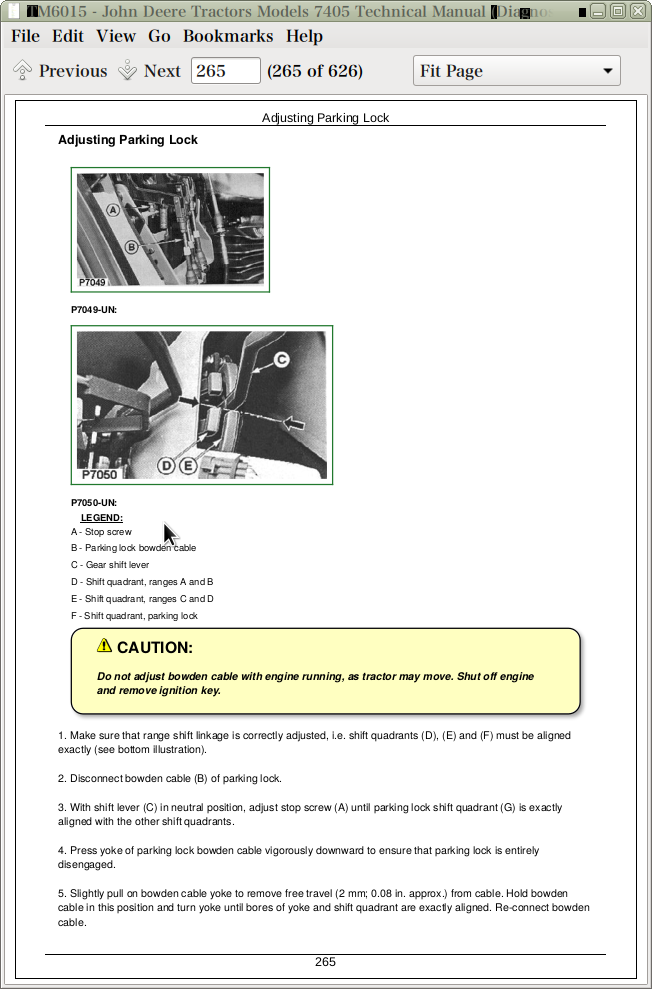
Adjusting Parking Lock
Adjusting Reverse Drive Linkage
Group 20: Theory of Operation - PowrQuad Transmission
PowrQuad Transmission Schematic-Early Version (Component Identification)
Guide to PowrQuad Transmission Theory
PowrQuad Transmission
Planetary Operation
Test Port and Sensor Identification
Air Pump
Transmission Oil Pump
Clutch Oil Manifold
Reverse Brake Housing
Filter Relief Valve
Pressure Regulating Valve
Speed Control Circuit
EOV Circuit (With Mechanical Reverser Control)
Shift Lever Moved From Forward or Reverse to Neutral:
Traction Clutch Cooling Oil Components
Oil Cooler System
Low-Pressure Clutch Cooling Valve
FWD-REV Cooling Control Valve
High-Pressure Clutch Cooling Valve
Clutch Pedal Control of Cooling Flow:
Cooler and Lube Circuits
Module Lube
Module Lube Flow Paths
Clutch Cooling Circuit Operation
Oil Cooler
Creeper Transmission Operation
Range Box
PowrQuad Transmission (Symbols)
Section 256: Drive Systems
Group 05: Operational Checks
Checking Rear PTO
Group 10: System Diagnosis
Mechanical Front Wheel Drive
Differential
Final Drives
Rear PTO
Group 15: System Tests
Safety Precautions
Special or Essential Tools
Specifications
Heating up Hydraulic Oil
Testing System Pressure of MFWD Clutch
Testing System Pressure of Hydraulic Differential Lock
Testing Rear PTO
Testing Lube Pressure of FWD Clutch, Differential Lock and PTO
Group 20A: Front Wheel Drive Clutch
Layout
Oil and Power Flows With Front Wheel Drive Engaged
Oil and Power Flows With Front Wheel Drive Disengaged
Group 20B: Differential
Layout
Power Flow When Moving Straight Ahead
Power Flow When Cornering
Oil Flow With Differential Locked Engaged
Oil Flow Differential Lock Disengaged
Group 20C: Final Drives
Final Drive Operation
Group 20D: Rear PTO Options
Description of Rear PTO Options
PTO Modulating Valve and Solenoid Valve
PTO Clutch and Brake
Lube Cut-Off Valve
PTO Power Flow (540/1000 RPM, Reversible)
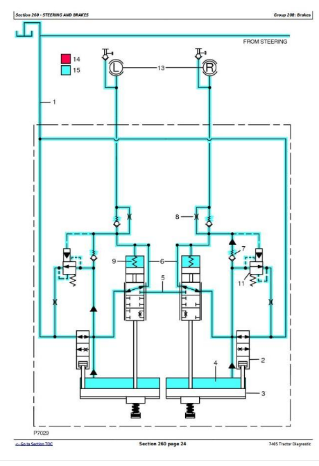
Section 260: Steering and Brakes
Group 05: Operational Checks
Checking Steering
CHecking Brakes
CHecking Handbrake
Group 10: System de Diagnosis
Hydrostatic Steering
Hydraulic Brakes
Group 15: System Tests
Special or Essential Tools
Checking Steering System for External Leakage
CHecking Steering System for Internal Leakage
Testing Leaf Springs of Steering Valve
Checking Steering Valve for Leakage
Steering Valve Hydraulic Connections
Testing and Adjusting Shock Valves
Checking Brake System
CHecking Brakes for Air in the System
CHecking Brakes for External Leakage
Checking Brake Valve for Internal Leakage
Checking Brakes
Bleeding Brakes
Group 20: Theory of Operation (Complete System)
Description
Group 20A: Hydrostatic Steering
Description of Steering Valve
Operation of Metering Unit
Oil Flow in Steering System
Oil Flow - Neutral Position
Oil Flow - Emergency Steering
Various Types of Steering Valve
Group 20B: Brakes
Brake Pistons, Plates and Disks Operation
Steering and Brakes Theory of Operation/Brakes Released
Steering and Brakes Theory of Operation/Brakes Released
Steering and Brakes Theory of Operation/Braking Prefill
Steering and Brakes Theory of Operation/Braking Prefill
Steering and Brakes Theory of Operation/Braking Engaging
Steering and Brakes Theory of Operation/Braking Engaging
Section 270: Hydraulic System
Group 05: Operational Checks
Explanation of Operational Checks
Safety Precautions
Operational Checks on Rockshaft Control
Group 11: System Diagnosis in Hydraulic System
Explanation of System Diagnosis
Safety Precautions
Special or Essential Tools
Connecting Testers to Test Ports
Heating up Hydraulic Oil
Specifications
Test Sequence
System Diagnosis in Hydraulic Circuit
Information on System Diagnosis
Hydraulic System Response to a Missing Shuttle Valve
Measuring Flow Rate of Hydraulic Pump
Test Result Table
Group 15: System Tests
Explanation of the Hydraulic Tests
Safety Precautions
Special or Essential Tools
Heating up Hydraulic Oil
CHecking and Adjusting (Calibrating) Rockshaft Control
Checking withTthe Performance Monitor
Abbreviations Used in the Display
Designation of Controls
Test Sequence
Error Code List
Error Code List (Continued)
Error Code List (Continued)
Diagnostic Mode List
Diagnostic Mode List
Identification of Electronic Control Unit (HCU)
Calibration Program
Additional Checks
Checking and Adjusting Draft Sensor
Group 20: Hydraulic Circuits
Hydraulic Symbols
Description of Hydraulic System
Hydraulic Circuit - Theory of Operation
Hydraulic System and Components/Operation of Hydraulic System
Hydraulic System and Components/Operation of Hydraulic System
Description of Hydraulic Pump* Constant flow pump
Layout of Oil Lines
Hydraulic Pump - Theory of Operation
Hydraulic Oil Filter With Filter Relief Valve
Oil Cooler
Primary Filter
Shuttle Valves - Theory of Operation
Main Block With Inlet Priority Valve and By-Pass Valve
Inlet Priority Valve and By-Pass Valve - Theory of Operation
Hitch Control Valve
Pressure and Return Solenoid Valves On (No Signal from HCU)
Pressure and Return Solenoid Valves Off (Signal from HCU)
Hitch Control Valve - Neutral Position
Pressure Compensator Valve
Load Check Valve
Surge Relief Valve
Hitch Load-Sense Check Valve
Hitch Operation-Raising
Hitch Operation-Raised
Hitch Operation-Stopped
Hitch Operation-Lower
Hitch OperationFull Lower
Three Point Hitch Hydraulic Operation
Hitch Controls
Electro-Hydraulic Hitch Circuit
Electro-Hydraulic Hitch Circuit-Continued
Hitch Control Unit (HCU)
Operator Controls
Hitch Control Lever
Load/Depth Control Potentiometer
Rate-of-Drop Control Potentiometer
Raise Limit Control Potentiometer
Console Raise/Lower Rocker Switch
Hitch Sensing Devices
Hitch Position Feedback Sensor
Load/Draft Sensor
Group 25: Hydraulic System and Components
Selective Control Valves
101 Series Selective Control Valve-Neutral Position
101 Series SCV - Extend
101 Series SCV - Retract
101 Series SCV - Float Position
301 Series Selective Control Valve-Neutral
301 Series Selective Control Valve - Extend
301 Series Selective Control Valve-Retract
301 Series Selective Control Valve-Float
Quick Couplers
John Deere Tractors Models 7405 Diagnosis and Tests Service Technical Manual (TM6015)
![]()