
John Deere Tractors 7130 Premium, 7230 Premium, 7330 Premium, 7430 Premium, 7530 Premium Diagnosis and Tests Service Technical Manual (TM400019)

Complete Diagnosis & Tests Technical Manual with electrical wiring diagrams for John Deere 2WD or MFWD Tractors 7130, 7230, 7330, 7430 & 7530 Premium (North American Edition), with all the shop information to maintain, diagnose, and rebuild like professional mechanics.
John Deere 7130, 7230, 7330, 7430 & 7530 Premium Tractors workshop Diagnosis & Tests technical manual includes:
* Numbered table of contents easy to use so that you can find the information you need fast.
* Detailed sub-steps expand on repair procedure information
* Numbered instructions guide you through every repair procedure step by step.
* Troubleshooting and electrical service procedures are combined with detailed wiring diagrams for ease of use.
* Notes, cautions and warnings throughout each chapter pinpoint critical information.
* Bold figure number help you quickly match illustrations with instructions.
* Detailed illustrations, drawings and photos guide you through every procedure.
* Enlarged inset helps you identify and examine parts in detail.
tm400019 - 7130—7530 Premium Tractors Diagnostics - (North American Edition) Technical Manual.pdf
tm400019 - 7130—7530 Premium Tractors Diagnostics - (North American Edition) Technical Manual.epub
Total Pages: 8,482 pages
File Format: PDF/EPUB/MOBI/AZW (PC/Mac/Android/Kindle/iPhone/iPad; bookmarked, ToC, Searchable, Printable)
Language: English
MAIN SECTIONS
Foreword
Serial Number Break 2008
General Information
Safety Measures
General References
Diagnostic Trouble Codes
ATC Control Unit
BCU Control Unit
BIF Control Unit
DSM Control Unit
DTI Control Unit
ECU Control Unit
EPC Control Unit
ETC Control Unit
JDL Control Unit
PLC Control Unit
SIC Control Unit
SSU Control Unit
TCU Control Unit
TEC Control Unit
TEI Control Unit
TSC Control Unit
UIC Control Unit
UIM Control Unit
VTI Control Unit
Observable Symptoms
Electrical System
Electronic Control Units
AutoPowr/IVT Transmission
PowrQuad Transmission
Drive Train (without Transmission)
Steering and Brakes
Hydraulic System
Miscellaneous
Operator`s Cab
System Diagnostics
Electronic Control Units
PowrQuad Transmission
Hydraulic System
JDL - System Diagnostics
VTI (GreenStar) - System Diagnostics
Engine
General Information
Operational Checks
Tests and Adjustments
Fuel, Air Intake and Cooling Systems
Tests and Adjustments
Fuel System
Air Intake System
Cooling System
Cold-Weather Starting Aids
Electrical System
Starting Motor and Charging Circuit
Fuel Preheater
Electrical Starting Aid
BIF Control Unit (Basic Informator)
Horn
Operator`s Seat and Cigarette Lighter
Lights
Connector for Accessories
Radio Light, Dome Light, Console Light and Access Step Lights
ATC/ETC/HTC Control Units (Air Conditioning, Fan and Heater)
3- and 7-Terminal Power Outlet Sockets
BCU Control Unit (Electronic Hitch Control)
BCU Control Unit (Basic Functions)
Signal Socket and Service Socket
TSC Control Unit (Suspension)
SIC Control Unit (Selective Control Valves)
CAN BUS Terminating Resistor
Level 14 ECU Control Unit (Electronic Engine Control) for 4-Valve Engine with HPCR
Level 16 ECU Control Unit (Electronic Engine Control) for 2-Valve Engine with HPCR
TCU Control Unit (Transmission Control with AutoPowr/IVT Transmission)
EPC Control Unit (Transmission Control with PowrQuad Plus or AutoQuad Plus Transmission)
UIC Control Unit (Transmission Control with AutoPowr/IVT Transmission)
PLC Control Unit (Electronic Park Lock with AutoPowr/IVT Transmission)
Electrical Outside Mirrors
JDL Control Unit (JDLink)
TEC Control Unit (ISOBUS)
GreenStar (AMS)
SSU Control Unit (AutoTrac)
UIM/VTI Control Units (GreenStar Display)
Electro-Hydraulic Pick-Up Hitch
PC6 Power Module (HF)
PC0 Power Module
PC5 Power Module
DTI Control Unit (CommandCenter)
Component Information - Connectors and Contacts
Component Information - Connectors (X001 to X249)
Component Information - Connectors (X250 to X499)
Component Information - Connectors (X500 to X749)
Component Information - Connectors (X750 to X999)
Component Information - Connectors (XGND)
Component Information - Wiring Harnesses
Component Information - Electrical Parts/Components
Component Information - Electrical Parts/Components (Actuators)
Component Information - Electrical Parts/Components (Sensors/Switches/Potentiometers)
Component Information - Electrical Parts/Components (Fuses/Relays/Diodes)
Component Information - Electrical Parts/Components (Headlamps/Lights)
Component Information - Electrical Parts/Components (Other)
Component Information - Ground Connections
Component Information - CAN BUS Systems
Electronic Control Units
Operation and General Information on Diagnostics
Interactive Tests
Interactive Calibrations
Information on How to Reprogram Control Units
Data BUS Systems
ATC Control Unit
BCU Control Unit
BIF Control Unit
DSM Control Unit
DTI Control Unit
ECU Control Unit
EPC Control Unit
ETC Control Unit
JDL Control Unit
PC0 Power Module
PC5 Power Module
PC6 Power Module (HF)
PLC Control Unit
SIC Control Unit
SSU Control Unit
TCU Control Unit
TEC Control Unit
TSC Control Unit
UIC Control Unit
UIM Control Unit
VTI Control Unit
AutoPowr/IVT Transmission
Operational Checks
Tests and Adjustments
Theory of Operation
PowrQuad Transmission
Operational Checks
Tests and Adjustments
Theory of Operation
Drive Train (without Transmission)
Operational Checks
Tests and Adjustments
Front-Wheel Drive Clutch
Differential
Final Drives
Rear PTO Options
Steering and Brakes
Introductory Checks
Operational Checks
Tests and Adjustments
Hydrostatic Steering
Brake Valve
Rear Brakes
AutoTrac
Hydraulic System
Operational Checks
Tests and Adjustments
Theory of Operation
Oil Filter, Charge Pump and Hydraulic Pump
Hitch
Selective control valves (SCVs)
Independent Control Valves (ICVs)
Hydraulic block
Miscellaneous
Functional Tests
Tests and Settings
Operation
Operator`s Cab
Functional Tests
Tests and Settings
Ventilation/Heating
Air-conditioning system
ClimaTrak
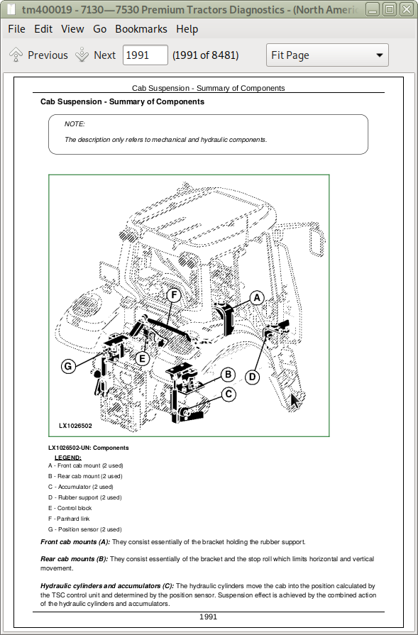
Cab Suspension
Special Tools
Special Tools (Dealer-Fabricated)
Special Tools (Available as Spare Parts)
tm400019 - 7130—7530 Premium TractorsDiagnostics -: (North American Edition)
Table of Contents
Foreword
Serial Number Break 2008
Section 210: General Information
Group 05: Safety Measures
Safety Information
Recognize Safety Information
”Important” Information
”Note” Information
Prevent Machine Runaway
Handle Fluids Safely—Avoid Fires
Prevent Battery Explosions
Prepare for Emergencies
Prevent Acid Burns
Avoid High-Pressure Fluids
Service Cooling System Safely
Remove Paint Before Welding or Heating
Avoid Heating Near Pressurized Fluid Lines
Work In Ventilated Area
Wear Protective Clothing
Practice Safe Maintenance
Park Machine Safely
Use Proper Lifting Equipment
Construct Dealer-Made Tools Safely
Support Machine Properly
Work in Clean Area
Illuminate Work Area Safely
Service Machines Safely
Use Proper Tools
Service Tires Safely
Service Front-Wheel Drive Tractor Safely
Safety Information - Air Brake System
Avoid Eye Contact With Radar
Keep ROPS Installed Properly
Replace Safety Signs
Dispose of Waste Properly
Live With Safety
Safety Measures on Electronic Control Units
Safety Instructions for Replacing a Halogen Bulb
Safety Instructions for Replacing Xenon (HID) Bulbs and Ballast Units
Group 10: General References
General Information - General References, Summary of References
General Information - Trademarks
General Information - Transmission and Hydraulic System, Introductory Checks
General Information - Inch Bolt and Cap Screws, Torque Values
General Information - Metric Bolt and Cap Screws, Torque Values
General Information - Hydraulic System Inch Fittings, Torque Values
General Information - Hydraulic System Metric Fittings, Torque Values
General Information - Electrical System, Component Identification Table
General Information - Electrical System, How to Read a Diagnostic Schematic
General Information - Electrical System, Lead Numbers and Color Codes
General Information - Electrical System, Symbols in Schematic, Wiring and Harness Diagrams
General Information - Electrical System, Approach to Tabular Diagnostic Procedures
General Information - Electrical System, Troubleshooting Unsolved Problems
General Information - Electrical System, Worksheet for Circuit/Harness Test
General Information - Electrical System, Visual Check
General Information - Electrical System, Electrical Circuit Malfunctions
General Information - Electrical System, Seven-Step Test Procedure
General Information - Hydraulic System, Symbols in Circuit Diagrams
General Information - Check the Oil Sight-Glass (when the Tire Combination has been Changed)
General Information - Country Version
Section 211: Diagnostic Trouble Codes
Group ATC: ATC Control Unit
ATC 000168.03 - Control Unit, Supply Voltage Too High
ATC 000168.04 - Control Unit, Supply Voltage Too Low
ATC 000170.03 - B127 - Sensor for Inside Air Temperature, Voltage Too High
ATC 000170.04 - B127 - Sensor for Inside Air Temperature, Voltage Too Low
ATC 000628.12 - Control Unit Internal Fault
ATC 000630.02 - Control Unit Internal Fault
ATC 000639.14 - Vehicle CAN BUS, Very High Error Rate
ATC 000871.03 - B130 - Sensor for Refrigerant Pressure, Voltage Too High
ATC 000871.04 - B130 - Sensor for Refrigerant Pressure, Voltage Too Low
ATC 000871.13 - B130 - Sensor for Refrigerant Pressure, Refrigerant Pressure Out of Valid Range Low
ATC 000876.00 - M02 - Compressor Clutch, Current Overload Protection Active at Power Module (HF) PC6
ATC 000876.01 - M02 - Compressor Clutch, Power Supply Fault at Power Module (HF) PC6
ATC 000876.04 - M02 - Compressor Clutch On, Current Too High at Power Module (HF) PC6
ATC 000876.05 - M02 - Compressor Clutch On, No Current Present at Power Module (HF) PC6
ATC 000876.09 - M02 - Compressor Clutch, Incorrect CAN BUS Message from ATC (Power Module (HF) PC6)
ATC 000876.12 - M02 - Compressor Clutch Off, Current Present at Power Module (HF) PC6
ATC 000876.19 - M02 - Compressor Clutch, Incorrect CAN BUS Message (Power Module (HF) PC6)
ATC 000923.00 - M07/M10 - Fan Motor, Current Overload Protection Active at Power Module (HF) PC6
ATC 000923.01 - M07/M10 - Fan Motor, Power Supply Fault at Power Module (HF) PC6
ATC 000923.04 - M07/M10 - Fan Motor On, Current Too High at Power Module (HF) PC6
ATC 000923.09 - M07/M10 - Fan Motor, Incorrect CAN BUS Message from ATC (Power Module (HF) PC6)
ATC 000923.12 - M07/M10 - Fan Motor Off, Current Present at Power Module (HF) PC6
ATC 000923.19 - M07/M10 - Fan Motor, Incorrect CAN BUS Message (Power Module (HF) PC6)
ATC 001079.03 - 5-volt Power Supply, Voltage Too High
ATC 001079.04 - 5-volt Power Supply, Voltage Too Low
ATC 001546.03 - B131 - Heater Valve (Potentiometer), Voltage Too High
ATC 001546.04 - B131 - Heater Valve (Potentiometer), Voltage Too Low
ATC 001547.03 - B129 - Sensor for Evaporator Core Temperature, Voltage Too High
ATC 001547.04 - B129 - Sensor for Evaporator Core Temperature, Voltage Too Low
ATC 001548.03 - B128 - Sensor for Outlet Temperature, Voltage Too High
ATC 001548.04 - B128 - Sensor for Outlet Temperature, Voltage Too Low
ATC 001549.03 - B131 - Heater Valve (Adjusting Motor), Voltage Too High
ATC 001549.04 - B131 - Heater Valve (Adjusting Motor), Voltage Too Low
ATC 001549.07 - B131 - Heater Valve, Fault
ATC 001549.13 - B131 - Heater Valve, Not Calibrated
ATC 001552.03 - Temperature Control, Voltage Too High
ATC 001552.04 - Temperature Control, Voltage Too Low
ATC 001553.03 - Fan Speed Control, Voltage Too High
ATC 001553.04 - Fan Speed Control, Voltage Too Low
ATC 002000.09 - Incorrect CAN BUS Message, Coolant Temperature from ECU
ATC 002156.09 - Incorrect CAN BUS Message, Information from Power Module (HF) PC6
ATC 522343.00 - R17 - Resistor at Heated Rear Window, Current Overload Protection Active at Power Module (HF) PC6
ATC 522343.01 - R17 - Resistor at Heated Rear Window, Power Supply Fault at Power Module (HF) PC6
ATC 522343.04 - R17 - Resistor at Heated Rear Window On, Current Too High at Power Module (HF) PC6
ATC 522343.05 - R17 - Resistor at Heated Rear Window On, No Current Present at Power Module (HF) PC6
ATC 522343.09 - R17 - Resistor at Heated Rear Window, Incorrect CAN BUS Message from ATC (Power Module (HF) PC6)
ATC 522343.12 - R17 - Resistor at Heated Rear Window Off, Current Present at Power Module (HF) PC6
ATC 522343.19 - R17 - Resistor at Heated Rear Window, Incorrect CAN BUS Message (Power Module (HF) PC6)
ATC 523848.03 - B132 - Adjusting Motor for Air Distribution (Potentiometer), Voltage Too High
ATC 523848.04 - B132 - Adjusting Motor for Air Distribution (Potentiometer), Voltage Too Low
ATC 523848.05 - B132 - Adjusting Motor for Air Distribution, Current Too Low
ATC 523848.06 - B132 - Adjusting Motor for Air Distribution, Current Too High
ATC 523848.07 - B132 - Adjusting Motor for Air Distribution, Fault
ATC 523848.13 - B132 - Adjusting Motor for Air Distribution, Not Calibrated
ATC 523979.05 - S139 - Switch for Heated Rear Window, Current Too Low
ATC 523979.07 - S139 - Switch for Heated Rear Window, Fault
ATC 524202.03 - B126 - Sensor for Ambient Air Temperature (at Rear), Voltage Too High
ATC 524202.04 - B126 - Sensor for Ambient Air Temperature (at Rear), Voltage Too Low
ATC 524203.03 - B125 - Sensor for Ambient Air Temperature (at Front), Voltage Too High
ATC 524203.04 - B125 - Sensor for Ambient Air Temperature (Front), Voltage Too Low
ATC 524219.02 - B143 - Defog Sensor, Frequency out of Valid Range
ATC 524219.03 - B143 - Defog Sensor, Voltage Too High
ATC 524219.04 - B143 - Defog Sensor, Voltage Too Low
ATC 600006.13 - Diagnostic Trouble Code Not Known
Group BCU: BCU Control Unit
BCU 000084.02 - B09/B35 - Wheel Speed Sensor, Out of Range
BCU 000096.03 - B176 - Fuel Level Sensor, Voltage Too High
BCU 000096.04 - B176 - Fuel Level Sensor, Voltage Too Low
BCU 000096.17 - Fuel Level Too Low
BCU 000115.31 - G02 - Alternator, Malfunction
BCU 000168.03 - Control Unit, Supply Voltage Too High
BCU 000168.04 - Control Unit, Supply Voltage Too Low
BCU 000168.16 - Control Unit, Supply Voltage Too High
BCU 000168.17 - Control Unit, Supply Voltage Too Low (Engine Speed Above 1500 rpm)
BCU 000168.18 - Control Unit, Supply Voltage Too Low (Engine Speed Above 500 rpm)
BCU 000177.18 - Transmission Oil Temperature Too Low During Calibration
BCU 000186.02 - B06 - Sensor for Rear PTO Speed, Open Circuit
BCU 000186.15 - B06 - Rear PTO Speed Sensor, Speed Present Despite Rear PTO Being Switched Off
BCU 000186.17 - B06 - Rear PTO Speed Sensor, Speed Not Present
BCU 000190.02 - B72 - Crankshaft Speed Sensor, Open Circuit
BCU 000237.02 - VIN Information, Mismatch
BCU 000237.14 - VIN Information, System Deactivated
BCU 000237.31 - VIN Information, Incorrect
BCU 000629.12 - Control Unit Internal Fault
BCU 000639.12 - Vehicle CAN BUS, High Error Rate
BCU 000639.14 - Vehicle CAN BUS, Very High Error Rate
BCU 000746.31 - Y05 - Differential Lock Solenoid Valve, Fault
BCU 000980.07 - S21 - Rear PTO Switch, Fault
BCU 001058.18 - INFORMATION FOR OPERATOR: Pressure Switch for Air-Brake System Is Not Activated (Pressure Too Low)
BCU 001079.03 - B41 - Draft Sensor, Voltage Too High
BCU 001079.04 - B41 - Draft Sensor, Voltage Too Low
BCU 001504.14 - INFORMATION FOR OPERATOR: Operator Presence Switch Not Activated While HMS Plus is Selected
BCU 001873.03 - B21 - Hitch Position Sensor, Voltage Too High
BCU 001873.04 - B21 - Hitch Position Sensor, Voltage Too Low
BCU 001873.15 - B21 - Hitch Position Sensor, Voltage Too High During Calibration
BCU 001873.17 - B21 - Hitch Position Sensor, Voltage Too Low During Calibration
BCU 001882.02 - B58 - Sensor for Front PTO Speed, Open Circuit
BCU 001882.15 - B58 - Front PTO Speed Sensor, Speed Present Despite Front PTO Being Switched Off
BCU 001882.17 - B58 - Front PTO Speed Sensor, Speed Not Present
BCU 001883.31 - Rear PTO Speed Too High
BCU 001890.03 - B179 - PTO Shaft Spline Identifier Switch, Voltage Too High
BCU 001890.04 - B179 - PTO Shaft Spline Identifier Switch, Supply Voltage Too Low
BCU 001890.31 - B179 - PTO Shaft Spline Identifier Switch, Fault
BCU 001893.07 - S06 - Front PTO Switch, Fault
BCU 001894.13 - Proportional Solenoid Valve for Rear PTO Not Calibrated
BCU 001894.31 - INFORMATION FOR OPERATOR: Rear PTO Switch was On When Engine was Started
BCU 001896.14 - INFORMATION FOR OPERATOR: Rear PTO Switch On Although Preselection of Rear PTO Speed Was in Neutral
BCU 001896.31 - INFORMATION FOR OPERATOR: Do Not Change Preselection of Rear PTO Speed Repeatedly
BCU 002000.09 - Incorrect CAN BUS Message, Information from ECU
BCU 002003.09 - Incorrect CAN BUS Message, Information from EPC/TCU
BCU 002005.09 - Incorrect CAN BUS Message, Information from UIC
BCU 002023.09 - Incorrect CAN BUS Message, Information from BIF
BCU 002040.09 - Incorrect CAN BUS Message, Information from DTI
BCU 002155.09 - Incorrect CAN BUS Message, Information from Power Module PC5 (Transmission)
BCU 002221.09 - Incorrect CAN BUS Message, Information from PLC
BCU 002240.09 - Incorrect CAN BUS Message, Information from TEC
BCU 002246.09 - Incorrect CAN BUS Message, Information from DSM
BCU 002354.00 - E09 - Front Corner Worklights, Current Overload Protection Active at Power Module (HF) PC6
BCU 002354.01 - E09 - Front Corner Worklights, Power Supply Fault at Power Module (HF) PC6
BCU 002354.04 - E09 - Front Corner Worklights On, Current Too High at Power Module (HF) PC6
BCU 002354.05 - E09 - Front Corner Worklights On, No Current Present at Power Module (HF) PC6
BCU 002354.09 - E09 - Front Corner Worklights, Incorrect CAN BUS Message from BCU (Power Module (HF) PC6)
BCU 002354.12 - E09 - Front Corner Worklights Off, Current Present at Power Module (HF) PC6
BCU 002354.19 - E09 - Front Corner Worklights, Incorrect CAN BUS Message (Power Module (HF) PC6)
BCU 002360.00 - E15 - Rear-Facing Worklights on Rear Fenders, Current Overload Protection Active at Power Module (HF) PC6
BCU 002360.01 - E15 - Rear-Facing Worklights on Rear Fenders, Power Supply Fault at Power Module (HF) PC6
BCU 002360.04 - E15 - Rear-Facing Worklights on Rear Fenders On, Current Too High at Power Module PC6
BCU 002360.05 - E15 - Rear-Facing Worklights on Fenders On, No Current Present at Power Module PC6
BCU 002360.09 - E15 - Rear-Facing Worklights on Fenders, Incorrect CAN BUS Message from BCU (Power Module (HF) PC6)
BCU 002360.12 - E15 - Rear-Facing Worklights on Rear Fenders Off, Current Present at Power Module (HF) PC6
BCU 002360.19 - E15 - Rear-Facing Worklights on Fenders, Incorrect CAN BUS Message (Power Module (HF) PC6)
BCU 002386.00 - E27 - Beacon Light, Current Overload Protection Active at Power Module (HF) PC6
BCU 002386.01 - E27 - Beacon Light, Power Supply Fault at Power Module PC6
BCU 002386.04 - E27 - Beacon Light On, Current Too High at Power Module PC6
BCU 002386.05 - E27 - Beacon Light On, No Current Present at Power Module PC6
BCU 002386.09 - E27 - Beacon Light, Incorrect CAN BUS Message from BCU (Power Module (HF) PC6)
BCU 002386.12 - E27 - Beacon Light Off, Current Present at Power Module (HF) PC6
BCU 002386.19 - E27 - Beacon Light, Incorrect CAN BUS Message (Power Module (HF) PC6)
BCU 002392.31 - H67 - Back-up Alarm, Malfunction
BCU 002818.31 - INFORMATION FOR OPERATOR: Operator Presence Switch Not Activated
BCU 002876.07 - S127 - Multi-Function Lever, Fault (Turn Signal)
BCU 003353.14 - G02 - Alternator, Malfunction
BCU 303053.03 - B26 - Sensitivity Potentiometer, Signal Voltage Too High
BCU 303053.04 - B26 - Sensitivity Potentiometer, Signal Voltage Too Low
BCU 303054.03 - B27 / B98 - Hitch-Height Control Potentiometer, Signal Voltage Too High
BCU 303054.04 - B27 / B98 - Hitch-Height Control Potentiometer, Signal Voltage Too Low
BCU 303056.03 - B27 - Raise-Limit Potentiometer, Signal Voltage Too High
BCU 303056.04 - B27 - Raise-Limit Potentiometer, Signal Voltage Too Low
BCU 303057.03 - B27 - Rate-of-Drop Potentiometer, Signal Voltage Too High
BCU 303057.04 - B27 - Rate-of-Drop Potentiometer, Signal Voltage Too Low
BCU 522451.03 - Non-Existent Function Activated
BCU 522451.04 - Non-Existent Function Activated
BCU 522451.14 - Non-Existent Function Activated
BCU 522507.31 - Control Unit Not Calibrated
BCU 523438.02 - Control Unit Internal Fault
BCU 523652.02 - Controller Connected to Wrong Wiring Harness Connector
BCU 523689.31 - S22 - Differential Lock Switch, Fault
BCU 523690.02 - S23/S68 - Switches for Remote Control of Rockshaft (Right/Left), Fault
BCU 523691.00 - Lower Worklights on Cab Frame, Current Overload Protection Active at Power Module (HF) PC6
BCU 523691.01 - Lower Worklights on Cab Frame, Incorrect Supply Voltage at Power Module (HF) PC6
BCU 523691.04 - Lower Worklights on Cab Frame On, Current Too High at Power Module (HF) PC6
BCU 523691.05 - Lower Worklights on Cab Frame On, No Current Present at Power Module (HF) PC6
BCU 523691.09 - Lower Worklights on Cab Frame, Incorrect CAN BUS Message from BCU (Power Module (HF) PC6)
BCU 523691.12 - Lower Worklights on Cab Frame Off, Current Present at Power Module (HF) PC6
BCU 523691.19 - Lower Worklights on Cab Frame, Incorrect CAN BUS Message (Power Module (HF) PC6)
BCU 523692.00 - Upper Worklights on Cab Frame, Current Overload Protection Active at Power Module PC0
BCU 523692.01 - Upper Worklights on Cab Frame, Power Supply Fault at Power Module PC0
BCU 523692.04 - Upper Worklights on Cab Frame On, Current Too High at Power Module PC0
BCU 523692.05 - Upper Worklights on Cab Frame On, No Current Present at Power Module PC0
BCU 523692.09 - Upper Worklights on Cab Frame, Incorrect CAN BUS Message from BCU (Power Module PC0)
BCU 523692.12 - Upper Worklights on Cab Frame Off, Current Present at Power Module PC0
BCU 523692.19 - Upper Worklights on Cab Frame, Incorrect CAN BUS Message (Power Module PC0)
BCU 523701.05 - M08 - Stepper Motor for Hitch (Coil 2), Open Circuit
BCU 523701.06 - M08 - Stepper Motor for Hitch (Coil 2), Current Too High
BCU 523702.14 - VIN Information, System De-Activated
BCU 523702.31 - VIN Information, Incorrect
BCU 523703.02 - B19 - Right Draft Sensor, Distorted Signal During Calibration
BCU 523703.03 - B19 - Right Draft Sensor, Voltage Too High During Calibration
BCU 523703.04 - B19 - Right Draft Sensor, Voltage Too Low During Calibration
BCU 523703.15 - B19 - Right Draft Sensor, Voltage Too High
BCU 523703.17 - B19 - Right Draft Sensor, Voltage Too Low
BCU 523704.02 - B20 - Left Draft Sensor, Distorted Signal During Calibration
BCU 523704.03 - B20 - Left Draft Sensor, Voltage Too High During Calibration
BCU 523704.04 - B20 - Left Draft Sensor, Voltage Too Low During Calibration
BCU 523704.15 - B20 - Left Draft Sensor, Voltage Too High
BCU 523704.17 - B20 - Left Draft Sensor, Voltage Too Low
BCU 523714.31 - Y71 - Solenoid Valve for Draft Link Stabilizer, Fault
BCU 523715.31 - Y72 - Solenoid Valve for Draft Link Stabilizer, Fault
BCU 523745.31 - S100 - HMS Plus Program Selector Switch, Fault
BCU 523746.31 - Control Unit Internal Fault
BCU 523749.31 - INFORMATION FOR OPERATOR: Rear PTO Not Operating. Switch Rear PTO Off and On Again
BCU 523751.05 - M08 - Stepper Motor for Hitch (Coil 1), Open Circuit
BCU 523751.06 - M08 - Stepper Motor for Hitch (Coil 1), Current Too High
BCU 523753.16 - M08 - Stepper Motor for Hitch, Raising Deadband Too High During Calibration
BCU 523753.18 - M08 - Stepper Motor for Hitch, Raising Deadband Too Low During Calibration
BCU 523756.16 - M08 - Stepper Motor for Hitch, Lowering Deadband Too High During Calibration
BCU 523756.18 - M08 - Stepper Motor for Hitch, Lowering Deadband Too Low During Calibration
BCU 523758.11 - S121 - Remote Control Switch for Rear PTO (Right), Fault
BCU 523759.11 - S44 - Remote Control Switch for Rear PTO (Left), Fault
BCU 523760.04 - Turn Signal/Hazard Flasher System, Supply Voltage Too Low
BCU 523760.31 - Turn-Signal/Hazard Flasher System, Fault
BCU 523806.00 - Y75 - Solenoid for PTO Speed 3, Current Overload Protection Active at Power Module PC5
BCU 523806.01 - Y75 - Solenoid for PTO Speed 3, Power Supply Fault at Power Module PC5
BCU 523806.04 - Y75 - Solenoid for PTO Speed 3 On, Current Too High at Power Module PC5
BCU 523806.05 - Y75 - Solenoid for PTO Speed 3 On, No Current Present at Power Module PC5
BCU 523806.09 - Y75 - Solenoid for PTO Speed 3, Incorrect CAN BUS Message from BCU (Power Module PC5)
BCU 523806.12 - Y75 - Solenoid for PTO Speed 3 Off, Current Present at Power Module PC5
BCU 523806.19 - Y75 - Solenoid for PTO Speed 3, Incorrect CAN BUS Message (Power Module PC5)
BCU 523811.00 - Y73 - Solenoid for PTO Speed 1, Current Overload Protection Active at Power Module PC5
BCU 523811.01 - Y73 - Solenoid for PTO Speed 1, Power Supply Fault at Power Module PC5
BCU 523811.04 - Y73 - Solenoid for PTO Speed 1 On, Current Too High at Power Module PC5
BCU 523811.05 - Y73 - Solenoid for PTO Speed 1 On, No Current Present at Power Module PC5
BCU 523811.09 - Y73 - Solenoid for PTO Speed 1, Incorrect CAN BUS Message from BCU (Power Module PC5)
BCU 523811.12 - Y73 - Solenoid for PTO Speed 1 Off, Current Present at Power Module PC5
BCU 523811.19 - Y73 - Solenoid for PTO Speed 1, Incorrect CAN BUS Message (Power Module PC5)
BCU 523812.00 - Y74 - Solenoid for PTO Speed 2, Current Overload Protection Active at Power Module PC5
BCU 523812.01 - Y74 - Solenoid for PTO Speed 2, Power Supply Fault at Power Module PC5
BCU 523812.04 - Y74 - Solenoid for PTO Speed 2 On, Current Too High at Power Module PC5
BCU 523812.05 - Y74 - Solenoid for PTO Speed 2 On, No Current Present at Power Module PC5
BCU 523812.09 - Y74 - Solenoid for PTO Speed 2, Incorrect CAN BUS Message from BCU (Power Module PC5)
BCU 523812.12 - Y74 - Solenoid for PTO Speed 2 Off, Current Present at Power Module PC5
BCU 523812.19 - Y74 - Solenoid for PTO Speed 2, Incorrect CAN BUS Message (Power Module PC5)
BCU 523813.00 - Y73 - Solenoid for PTO Speed 1, Current Overload Protection Active at Power Module PC5
BCU 523813.01 - Y73 - Solenoid for PTO Speed 1, Power Supply Fault at Power Module PC5
BCU 523813.04 - Y73 - Solenoid for PTO Speed 1 On, Current Too High at Power Module PC5
BCU 523813.05 - Y73 - Solenoid for PTO Speed 1 On, No Current Present at Power Module PC5
BCU 523813.09 - Y73 - Solenoid for PTO Speed 1, Incorrect CAN BUS Message from BCU (Power Module PC5)
BCU 523813.12 - Y73 - Solenoid for PTO Speed 1 Off, Current Present at Power Module PC5
BCU 523813.19 - Y73 - Solenoid for PTO Speed 1, Incorrect CAN BUS Message (Power Module PC5)
BCU 523814.00 - Y74 - Solenoid for PTO Speed 2, Current Overload Protection Active at Power Module PC5
BCU 523814.01 - Y74 - Solenoid for PTO Speed 2, Power Supply Fault at Power Module PC5
BCU 523814.04 - Y74 - Solenoid for PTO Speed 2 On, Current Too High at Power Module PC5
BCU 523814.05 - Y74 - Solenoid for PTO Speed 2 On, No Current Present at Power Module PC5
BCU 523814.09 - Y74 - Solenoid for PTO Speed 2, Incorrect CAN BUS Message from BCU (Power Module PC5)
BCU 523814.12 - Y74 - Solenoid for PTO Speed 2 Off, Current Present at Power Module PC5
BCU 523814.19 - Y74 - Solenoid for PTO Speed 2, Incorrect CAN BUS Message (Power Module PC5)
BCU 523815.00 - Y75 - Solenoid for PTO Speed 3, Current Overload Protection Active at Power Module PC5
BCU 523815.01 - Y75 - Solenoid for PTO Speed 3, Power Supply Fault at Power Module PC5
BCU 523815.04 - Y75 - Solenoid for PTO Speed 3 On, Current Too High at Power Module PC5
BCU 523815.05 - Y75 - Solenoid for PTO Speed 3 On, No Current Present at Power Module PC5
BCU 523815.09 - Y75 - Solenoid for PTO Speed 3, Incorrect CAN BUS Message from BCU (Power Module PC5)
BCU 523815.12 - Y75 - Solenoid for PTO Speed 3 Off, Current Present at Power Module PC5
BCU 523815.19 - Y75 - Solenoid for PTO Speed 3, Incorrect CAN BUS Message (Power Module PC5)
BCU 523826.03 - Non-Existent Function Activated
BCU 523826.04 - Non-Existent Function Activated
BCU 523834.03 - B27 - Depth-Setting Potentiometer, Voltage Too High
BCU 523834.04 - B27 - Depth-Setting Potentiometer, Voltage Too Low
BCU 523839.14 - INFORMATION FOR OPERATOR: Handbrake is On and a Gear is Selected
BCU 523839.31 - INFORMATION FOR OPERATOR: Handbrake Activated While Wheel Speed is Recognized
BCU 523843.02 - S24 - Quick Withdrawal Switch, Switch Status out of Valid Range
BCU 523843.03 - S24 - Quick Withdrawal Switch, Voltage Too High
BCU 523843.04 - S24 - Quick Withdrawal Switch, Voltage Too Low
BCU 523904.31 - INFORMATION FOR OPERATOR: Operator Presence Switch Not Activated While Front PTO is Engaged
BCU 523905.31 - Y01 - Front PTO Solenoid Valve, Fault
BCU 523908.14 - INFORMATION FOR OPERATOR: Remote Control Switch for Rear PTO is Activated
BCU 523908.31 - INFORMATION FOR OPERATOR: Rear PTO Can Now Be Switched On at Rear PTO Remote Control Switch
BCU 523919.00 - E18/1 - Inner Worklights on Front of Roof, Current Overload Protection Active at Power Module PC0
BCU 523919.01 - E18/1 - Inner Worklights on Front of Roof, Power Supply Fault at Power Module PC0
BCU 523919.04 - E18/1 - Inner Worklights on Front of Roof On, Current Too High at Power Module PC0
BCU 523919.05 - E18/1 - Inner Worklights on Front of Roof On, No Current Present at Power Module PC0
BCU 523919.09 - E18/1 - Inner Worklights on Front of Roof, Incorrect CAN BUS Message from BCU (Power Module PC0)
BCU 523919.12 - E18/1 - Inner Worklights on Front of Roof Off, Current Present at Power Module PC0
BCU 523919.19 - E18/1 - Inner Worklights on Front of Roof, Incorrect CAN BUS Message (Power Module PC0)
BCU 523920.00 - E18/2 - Outer Worklights on Front of Roof, Current Overload Protection Active at Power Module PC0
BCU 523920.01 - E18/2 - Outer Worklights on Front of Roof, Power Supply Fault at Power Module PC0
BCU 523920.04 - E18/2 - Outer Worklights on Front of Roof On, Current Too High at Power Module PC0
BCU 523920.05 - E18/2 - Outer Worklights on Front of Roof On, No Current Present at Power Module PC0
BCU 523920.09 - E18/2 - Outer Worklights on Front of Roof, Incorrect CAN BUS Message from BCU (Power Module PC0)
BCU 523920.12 - E18/2 - Outer Worklights on Front of Roof Off, Current Present at Power Module PC0
BCU 523920.19 - E18/2 - Outer Worklights on Front of Roof, Incorrect CAN BUS Message (Power Module PC0)
BCU 523921.00 - E11/2 /E31R - Worklights on Rear of Roof, Current Overload Protection Active at Power Module PC0
BCU 523921.01 - E11/2 /E31R - Worklights on Rear of Roof, Power Supply Fault at Power Module PC0
BCU 523921.04 - E11/2 /E31R - Worklights on Rear of Roof On, Current Too High at Power Module PC0
BCU 523921.05 - E11/2 /E31R - Worklights on Rear of Roof On, No Current Present at Power Module PC0
BCU 523921.09 - E11/2 /E31R - Worklights on Rear of Roof, Incorrect CAN BUS Message from BCU (Power Module PC0)
BCU 523921.12 - E11/2 /E31R - Worklights on Rear of Roof Off, Current Present at Power Module PC0
BCU 523921.19 - E11/2 /E31R - Worklights on Rear of Roof, Incorrect CAN BUS Message (Power Module PC0)
BCU 523924.00 - E31-L - Left Xenon (HID) Worklight on Rear of Roof, Current Overload Protection Active at Power Module PC0
BCU 523924.01 - E31-L - Left Xenon (HID) Worklight on Rear of Roof, Power Supply Fault at Power Module PC0
BCU 523924.04 - E31-L - Left Xenon (HID) Worklight on Rear of Roof, Current Too High at Power Module PC0
BCU 523924.05 - E31-L - Left Xenon (HID) Worklight on Rear of Roof Switched On, No Current Present at Power Module PC0
BCU 523924.09 - E31-L - Left Xenon (HID) Worklight on Rear of Roof, Incorrect CAN BUS Message from BCU
BCU 523924.12 - E31-L - Left Xenon (HID) Worklight on Rear of Roof Switched Off, Current Present at Power Module PC0
BCU 523924.19 - E31-L - Left Xenon (HID) Worklight on Rear of Roof, Incorrect CAN BUS Message (Power Module PC0)
BCU 524055.11 - Control Unit Internal Fault
BCU 524055.31 - Control Unit Not Calibrated
BCU 524216.02 - INFORMATION FOR OPERATOR: Switch Off the Front PTO Switch
BCU 524216.14 - INFORMATION FOR OPERATOR: Switch On the Front PTO Switch.
BCU 524216.31 - INFORMATION FOR OPERATOR: Front PTO was Switched On When Engine Was Started
BCU 524224.02 - INFORMATION FOR OPERATOR: Switch Off the Rear PTO Switch
BCU 524224.14 - INFORMATION FOR OPERATOR: Switch On the Rear PTO Switch.
BCU 524224.31 - INFORMATION FOR OPERATOR: Rear PTO Was Switched On When Engine Was Started
BCU 524235.31 - Y03 - Front-Wheel Drive Solenoid Valve, Fault
BCU 524252.31 - Y04/Y81 - Solenoid Valve (Proportional Solenoid Valve) for Rear PTO, Fault
BCU 600006.31 - Diagnostic Trouble Code Not Known
Group BIF: BIF Control Unit
BIF 000168.16 - Control Unit, Supply Voltage Too High
BIF 000168.18 - Control Unit, Supply Voltage Too Low
BIF 000639.14 - Vehicle CAN BUS, Very High Error Rate
BIF 002000.09 - Incorrect CAN BUS Message, Sensor for Coolant Temperature from ECU
BIF 002003.09 - Incorrect CAN BUS Message, AutoQuad Information from EPC
BIF 002005.09 - Incorrect CAN BUS Message, Information from UIC
BIF 002033.09 - Incorrect CAN BUS Message, Information from BCU
BIF 002034.09 - Incorrect CAN BUS Message, Information from SIC (E-ICV/E-SCV Stepper Motors)
BIF 002040.09 - Incorrect CAN BUS Message, Lighting Information from DTI
BIF 002150.09 - Incorrect CAN BUS Message, Information from Power Module PC0
BIF 002156.09 - Incorrect CAN BUS Message, Information from Power Module (HF) PC6
BIF 002348.00 - E07/E08 - Headlights on Cab Frame (Full Beam), Current Overload Protection Active at Power Module PC0
BIF 002348.01 - E07/E08 - Headlights on Cab Frame (Full Beam), Power Supply Fault at Power Module PC0
BIF 002348.04 - E07/E08 - Headlights on Cab Frame (Full Beam) On, Current Too High at Power Module PC0
BIF 002348.05 - E07/E08 - Headlights on Cab Frame (Full Beam) On, No Current Present at Power Module PC0
BIF 002348.09 - E07/E08 - Headlights on Cab Frame (Full Beam), Incorrect CAN BUS Message from BIF (Power Module PC0)
BIF 002348.12 - E07/E08 - Headlights on Cab Frame (Full Beam) Off, Current Present at Power Module PC0
BIF 002348.19 - E07/E08 - Headlights on Cab Frame (Full Beam), Incorrect CAN BUS Message
BIF 002863.02 - S128 - Switch for Windshield and Rear Window Wipers, Fault at Windshield
BIF 002865.02 - S128 - Switch for Windshield and Rear Window Wipers, Fault at Rear Window
BIF 002873.31 - INFORMATION FOR OPERATOR: Switch Off Worklights while Driving on Road
BIF 002876.02 - S127 - Turn-Signal Lever, Fault
BIF 522426.00 - K06/05 or K02/05 - Relay for Rear Window Wiper, Current Overload Protection Active at Power Module (HF) PC6
BIF 522426.01 - K06/05 or K02/05 - Relay for Rear Window Wiper, Power Supply Fault at Power Module (HF) PC6
BIF 522426.04 - K06/05 or K02/05 - Relay for Rear Window Wiper On, Current Too High at Power Module (HF) PC6
BIF 522426.09 - K06/05 or K02/05 - Relay for Rear Window Wiper, Incorrect CAN BUS Message from BIF (Power Module (HF) PC6)
BIF 522426.12 - K06/05 or K02/05 - Relay for Rear Window Wiper Off, Current Present at Power Module (HF) PC6
BIF 522426.19 - K06/05 or K02/05 - Relay for Rear Window Wiper, Incorrect CAN BUS Message (Power Module (HF) PC6)
BIF 522427.00 - K06/04 or K02/04 - Relay for Windshield Wiper, Current Overload Protection Active at Power Module PC0
BIF 522427.01 - K06/04 or K02/04 - Relay for Windshield Wiper, Power Supply Fault at Power Module PC0
BIF 522427.04 - K06/04 or K02/04 - Relay for Windshield Wiper On, Current Too High at Power Module PC0
BIF 522427.09 - K06/04 or K02/04 - Relay for Windshield Wiper, Incorrect CAN BUS Message from BIF
BIF 522427.12 - K06/04 or K02/04 - Relay for Windshield Wiper Off, Current Present at Power Module PC0
BIF 522427.19 - K06/04 or K02/04 - Relay for Windshield Wiper, Incorrect CAN BUS Message
BIF 522434.00 - M03 - Windshield Wiper (Switch Set to Slow Wipe), Current Overload Protection Active at Power Module PC0
BIF 522434.01 - M03 - Windshield Wiper (Switch Set to Slow Wipe), Power Supply Fault at Power Module PC0
BIF 522434.04 - M03 - Windshield Wiper On (Switch Set to Slow), Current Too High at Power Module PC0
BIF 522434.05 - M03 - Windshield Wiper On (Switch Set to Slow Wipe), No Current Present at Power Module PC0
BIF 522434.09 - M03 - Windshield Wiper (Switch Set to Slow Wipe), Incorrect CAN BUS Message from BIF
BIF 522434.12 - M03 - Windshield Wiper (Slow Position) Off, Current Present at Power Module PC0
BIF 522434.19 - M03 - Windshield Wiper (Set to Slow Wipe), CAN BUS Message Faulty
BIF 522435.00 - M03 - Windshield Wiper (Set to Fast Wipe), Current Overload Protection Active at Power Module PC0
BIF 522435.01 - M03 - Windshield Wiper (Switch Set to Fast Wipe), Power Supply Fault at Power Module PC0
BIF 522435.04 - M03 - Windshield Wiper (Set to Fast Wipe), Switched Current Too High at Power Module PC0
BIF 522435.05 - M03 - Windshield Wiper (Set to Fast Wipe), Switched Current Not Present at Power Module PC0
BIF 522435.09 - M03 - Windshield Wiper (Switch Set to Fast Wipe), Incorrect CAN BUS Message from BIF
BIF 522435.12 - M03 - Windshield Wiper (Fast Position) Off, Current Present at Power Module PC0
BIF 522435.19 - M03 - Windshield Wiper (Set to Fast Wipe), CAN BUS Message Faulty
BIF 523438.02 - Control Unit Internal Fault
BIF 523900.00 - E07 - Left Headlight on Cab Frame (Dipped Beam), Current Overload Protection Active at Power Module PC0
BIF 523900.01 - E07 - Left Headlight on Cab Frame (Dipped Beam), Faulty Supply Voltage at Power Module PC0
BIF 523900.04 - E07 - Left Headlight on Cab Frame (Dipped Beam), Switched Current Too High at Power Module PC0
BIF 523900.05 - E07 - Left Headlight on Cab Frame (Dipped Beam), No Switched Current Present at Power Module PC0
BIF 523900.09 - E07 - Left Headlight on Cab Frame (Dipped Beam), Incorrect CAN BUS Message from BIF
BIF 523900.12 - E07 - Left Headlight on Cab Frame (Dipped Beam) Off, Current Present at Power Module PC0
BIF 523900.19 - E07 - Left Headlight on Cab Frame (Dipped Beam), Incorrect CAN BUS Message
BIF 523909.00 - E08 - Right Headlight on Cab Frame (Dipped Beam), Current Overload Protection Active at Power Module PC0
BIF 523909.01 - E08 - Right Headlight on Cab Frame (Dipped Beam), Power Supply Fault at Power Module PC0
BIF 523909.04 - E08 - Right Headlight on Cab Frame (Dipped Beam), Switched Current Too High at Power Module PC0
BIF 523909.05 - E08 - Right Headlight on Cab Frame (Dipped Beam), No Switched Current Present at Power Module PC0
BIF 523909.09 - E08 - Right Headlight on Cab Frame (Dipped Beam), Incorrect CAN BUS Message from BIF
BIF 523909.12 - E08 - Right Headlight on Cab Frame (Dipped Beam) Off, Current Present at Power Module PC0
BIF 523909.19 - E08 - Right Headlight on Cab Frame (Dipped Beam), Incorrect CAN BUS Message
BIF 600006.31 - Diagnostic Trouble Code Not Known
Group DSM: DSM Control Unit
DSM000168.03 - Control Unit, Supply Voltage Too High
DSM000168.04 - Control Unit, Supply Voltage Too Low
DSM000628.02 - Control Unit Internal Fault
DSM000629.12 - Control Unit Internal Fault
DSM000639.14 - Vehicle CAN BUS, Very High Error Rate
DSM523523.10 - Hotkey 13, Fault
DSM523524.10 - Hotkey for Raise Limit, Fault
DSM523525.10 - Hotkey for Load/Depth Adjustment, Fault
DSM523526.10 - Hotkey for Rate-of Drop, Fault
DSM523527.10 - Engine Hotkey, Fault
DSM523528.10 - Hotkey for Rear PTO Speed, Fault
DSM523529.10 - Transmission Hotkey, Fault
DSM523530.10 - Key for Engaging/Disengaging Front-Wheel Drive, Fault
DSM523531.10 - Hotkey for HMS, Fault
DSM523532.10 - Key for Engaging/Disengaging Front-Wheel Drive Automatic Mode, Fault
DSM523533.10 - Transport Lock Button (E-ICVs), Fault
DSM523534.10 - Hotkey for Selective Control Valves, Fault
DSM523535.10 - Transport Lock Button (E-SCVs), Fault
DSM523536.10 - Confirm Button, Fault
DSM523537.10 - Abort Button, Fault
DSM523538.10 - Main Menu Button, Fault
DSM523609.10 - Hotkey 15, Fault
DSM523610.10 - Hotkey 14, Fault
DSM523910.02 - Control Unit Internal Fault
DSM 600006.13 - Diagnostic Trouble Code Not Known
Group DTI: DTI Control Unit
DTI000158.03 - Control Unit, Supply Voltage (ELX) Too High
DTI000158.04 - Control Unit, Supply Voltage (ELX) Too Low
DTI 000168.03 - Control Unit, Supply Voltage (BAT) Too High
DTI 000168.04 - Control Unit, Supply Voltage (BAT) Too Low
DTI 000442.00 - Control Unit, Inside Temperature of CommandCenter (DTI) Too High
DTI 000442.01 - Control Unit, Inside Temperature of CommandCenter (DTI) Too Low
DTI 000444.03 - Control Unit, Supply Voltage Too High (RTC)
DTI 000444.04 - Control Unit, Supply Voltage Too Low (RTC)
DTI 000628.12 - Control Unit Internal Fault
DTI 000916.14 - INFORMATION FOR OPERATOR: Service
DTI 001491.11 - Background Lighting of CommandCenter (DTI), Fault
DTI 002000.09 - Incorrect CAN BUS Message, Information from ECU
DTI 002003.09 - Incorrect CAN BUS Message, Information from EPC or TCU
DTI 002005.09 - Incorrect CAN BUS Message, Information from UIC
DTI 002023.09 - Incorrect CAN BUS Message, Information from BIF
DTI 002025.09 - Incorrect CAN BUS Message, Information from ATC, ETC or HTC
DTI 002033.09 - Incorrect CAN BUS Message, Information from BCU
DTI 002034.09 - Incorrect CAN BUS Message, Information from SIC
DTI 002047.09 - Incorrect CAN BUS Message, Information from TSC
DTI 002246.09 - Incorrect CAN BUS Message, Information from DSM
DTI 523436.14 - Control Unit Internal Fault
DTI 523438.02 - Control Unit Internal Fault
DTI 523773.03 - Vehicle CAN BUS, CAN+ Voltage Too High
DTI 523773.04 - Vehicle CAN BUS, CAN+ Voltage Too Low
DTI 523774.03 - Vehicle CAN BUS, CAN- Voltage Too High
DTI 523774.04 - Vehicle CAN BUS, CAN- Voltage Too Low
DTI 524050.12 - Display for Date and Clock Time, Fault
DTI 524076.10 - Hotkey 5, Fault
DTI 524077.10 - Hotkey 4, Fault
DTI 524078.10 - Hotkey 3, Fault
DTI 524080.10 - Hotkey 2, Fault
DTI 524082.10 - Hotkey 1, Fault
DTI 524215.03 - ISOBUS, CAN+ Voltage Too High
DTI 524215.04 - ISOBUS, CAN+ Voltage Too Low
DTI 524217.03 - ISOBUS, CAN- Voltage Too High
DTI 524217.04 - ISOBUS, CAN- Voltage Too Low
DTI 600006.31 - Diagnostic Trouble Code Not Known
Group ECU: ECU Control Unit
ECU 000084.31 - Incorrect CAN BUS Message, Wheel Speed from BCU
ECU 000097.03 - Water-in-fuel-filter signal voltage high
ECU 000097.04 - Water-in-fuel-filter signal voltage low
ECU 000097.16 - Water In Fuel Detected
ECU 000100.01 - Engine Oil Pressure Extremely Low
ECU 000100.03 - Input voltage of engine oil pressure high
ECU 000100.04 - Input Voltage of Engine Oil Pressure Sensor Too Low
ECU 000100.18 - Engine Oil Pressure Moderately Low
ECU 000100.31 - Engine Oil Pressure Invalid
ECU 000102.02 - Manifold Air Pressure Invalid
ECU 000102.03 - Input Voltage of Manifold Air Pressure Sensor Too High
ECU 000102.04 - Input Voltage of Manifold Air Pressure Sensor Too Low
ECU 000103.00 - Turbocharger Overspeed (most severe)
ECU 000103.05 - Turbocharger Speed Sensor Current Too Low
ECU 000103.06 - Turbocharger Speed Sensor Current Too High
ECU 000103.08 - Turbocharger Speed Invalid
ECU 000103.31 - Turbocharger Speed Missing
ECU 000105.00 - Mixed Air Temperature of Exhaust Gas Recirculation (EGR) Extremely High
ECU 000105.03 - Input Voltage Too High for Mixed Air Temperature Sensor of Exhaust Gas Recirculation (EGR)
ECU 000105.04 - Input Voltage Too High for Mixed Air Temperature Sensor in Exhaust Gas Recirculation (EGR)
ECU 000105.15 - Exhaust Gas Recirculation (EGR) Mixed Air Temperature Slightly High
ECU 000105.16 - Mixed Air Temperature of Exhaust Gas Recirculation (EGR) is Moderately High
ECU 000107.00 - Engine Air Filter Restricted
ECU 000108.02 - Barometric Air Pressure Invalid
ECU 000110.00 - Engine Coolant Temperature Extremely High
ECU 000110.03 - Input Voltage of Engine Coolant Temperature Too High
ECU 000110.04 - Input Voltage of Engine Coolant Temperature Too Low
ECU 000110.15 - Engine Coolant Temperature Slightly High
ECU 000110.16 - Engine Coolant Temperature Moderately High
ECU 000110.17 - Engine Coolant Temperature Low (Least Severe Level)
ECU 000157.03 - Input Voltage Too High in Sensor for Fuel Rail Pressure
ECU 000157.04 - Fuel Rail Pressure Sensor Input Voltage Too Low
ECU 000157.10 - Fuel Rail Pressure Loss Detected
ECU 000157.17 - Fuel Rail Pressure Not Sufficient
ECU 000158.17 - ECU Power Down Error
ECU 000160.02 - Wheel Speed Signal Incorrect
ECU 000174.00 - Fuel Temperature Extremely High
ECU 000174.03 - Input voltage of fuel temperature is too high
ECU 000174.04 - Input voltage of fuel temperature is too low
ECU 000174.16 - Fuel Temperature Moderately High
ECU 000189.00 - Engine speed derate
ECU 000190.00 - Engine Overspeed Extreme
ECU 000190.16 - Engine Overspeed Moderate
ECU 000237.02 - VIN Information, Mismatch
ECU 000237.13 - VIN Information, Option Code Invalid
ECU 000237.31 - VIN Information, Incorrect
ECU 000412.00 - Exhaust Gas Recirculation (EGR) Exhaust Temperature Extremely High
ECU 000412.03 - Exhaust Gas Recirculation (EGR) Exhaust Temperature Sensor Input Voltage Too High
ECU 000412.04 - Exhaust Gas Recirculation (EGR) Exhaust Temperature Sensor Input Voltage Too Low
ECU 000412.15 - EGR Temperature Signal Slightly High
ECU 000412.16 - Exhaust Gas Recirculation (EGR) Exhaust Temperature Moderately High
ECU 000611.03 - Electronic Injector Wiring Shorted To Power Source
ECU 000611.04 - Electronic Injector Wiring Shorted To Ground
ECU 000627.01 - Electronic Injector Supply Voltage Lower than Expected
ECU 000629.12 - ECU Error (EEPROM)
ECU 000629.13 - ECU Error
ECU 000636.02 - Input Noise in Pump Position Sensor for Camshaft Speed
ECU 000636.05 - Current Too Low for Camshaft Speed Sensor
ECU 000636.06 - Pump position sensor too high
ECU 000636.08 - Pump Position Sensor Input Missing
ECU 000636.10 - Pattern Error in Input Signal for Camshaft Speed Sensor
ECU 000637.02 - Input Noise in Crankshaft Speed
ECU 000637.05 - Current Too Low for Crankshaft Speed Sensor
ECU 000637.06 - Current in pump position sensor too high
ECU 000637.07 - Crank Position/Pump Position Timing Moderately Out of Sync
ECU 000637.08 - Crank Sensor Signal Input Missing
ECU 000637.10 - Crank Sensor Input Pattern Error
ECU 000641.04 - Turbocharger Actuator Error
ECU 000641.05 - Current for Turbocharger Actuator too Low
ECU 000641.12 - ECU/Turbocharger Actuator Communication Error
ECU 000641.13 - Turbocharger Actuator Learned Value Error
ECU 000641.16 - Turbocharger Actuator Temperature Moderately High
ECU 000651.02 - Cylinder No.1 Electronic Injector Part Number Invalid
ECU 000651.05 - Cylinder No.1 Electronic Injector Circuit Open
ECU 000651.06 - Short-Circuit in Electronic Injector for Cylinder No. 1
ECU 000651.07 - Cylinder No.1 Electronic Injector Mechanical Failure
ECU 000651.13 - Cylinder No.1 Electronic Injector QR Code Invalid
ECU 000652.02 - Invalid Part Number of Electronic Injector for Cylinder No. 2
ECU 000652.05 - Open Circuit in Electronic Injector for Cylinder No.2
ECU 000652.06 - Short-Circuit in Electronic Injector for Cylinder No. 2
ECU 000652.07 - Cylinder No.2 Electronic Injector Mechanical Failure
ECU 000652.13 - Invalid QR Code of Electronic Injector for Cylinder No. 2
ECU 000653.02 - Invalid Part Number of Electronic Injector for Cylinder No. 3
ECU 000653.05 - Open Circuit in Electronic Injector for Cylinder No. 3
ECU 000653.06 - Short-Circuit in Electronic Injector for Cylinder No. 3
ECU 000653.07 - Mechanical Failure of Electronic Injector for Cylinder No. 3
ECU 000653.13 - Cylinder No.3 Electronic Injector QR Code Invalid
ECU 000654.02 - Cylinder No.4 Electronic Injector Part Number Invalid
ECU 000654.05 - Open Circuit in EUI for Cylinder #4
ECU 000654.06 - Short-Circuit in Electronic Injector for Cylinder No. 4
ECU 000654.07 - Mechanical Failure of Electronic Injector for Cylinder No. 4
ECU 000654.13 - Invalid QR Code in Electronic Injector for Cylinder No. 4
ECU 000655.02 - Cylinder No. 5 Electronic Injector Part Number Invalid
ECU 000655.05 - Cylinder No. 5 Electronic Injector Circuit Open
ECU 000655.06 - Cylinder No. 5 Electronic Injector Circuit Shorted
ECU 000655.07 - Cylinder No. 5 Electronic Injector Mechanical Failure
ECU 000655.13 - Cylinder No. 5 Electronic Injector QR Code Invalid
ECU 000656.02 - Cylinder No. 6 Electronic Injector Part Number Invalid
ECU 000656.05 - Cylinder No. 6 Electronic Injector Circuit Open
ECU 000656.06 - Cylinder No. 6 Electronic Injector Circuit Shorted
ECU 000656.07 - Cylinder No. 6 Electronic Injector Mechanical Failure
ECU 000656.13 - Cylinder No. 6 Electronic Injector QR Code Invalid
ECU 000676.03 - Glow Plug Relay Voltage Too High
ECU 000676.05 - Glow Plug Relay Voltage Too Low
ECU 001069.31 - Tire Size Error
ECU 001136.00 - ECU Temperature Extremely High
ECU 001136.16 - ECU Temperature Moderately High
ECU 001172.03 - Turbocharger Compressor Inlet Temperature Sensor Input Voltage Too High
ECU 001172.04 - Turbocharger Compressor Inlet Temperature Sensor Input Voltage Too Low
ECU 001180.00 - Turbocharger Turbine Inlet Temperature Extremely High
ECU 001180.16 - Turbocharger Turbine Inlet Temperature Moderately High
ECU 001347.03 - Pump Control Valve Current High
ECU 001347.05 - Pump Control Valve Current Mismatch
ECU 001347.07 - Fuel Rail Pressure Control Error
ECU 001569.31 - Fuel derate
ECU 002003.09 - Incorrect CAN BUS Message, CAN Message from EPC or TCU
ECU 002005.09 - Incorrect CAN BUS Message, CAN Message from UIC
ECU 002033.09 - Incorrect CAN BUS Message, CAN Message from BCU
ECU 002033.14 - Communication problem between ECU and BCU
ECU 002033.19 - Communication Problem between ECU and BCU
ECU 002630.00 - Exhaust Gas Recirculation (EGR) Fresh Air Temperature Extremely High
ECU 002630.03 - Exhaust Gas Recirculation (EGR) Fresh Air Temperature Sensor Input Voltage Too High
ECU 002630.04 - Exhaust Gas Recirculation (EGR) Fresh Air Temperature Sensor Input Voltage Too Low
ECU 002630.15 - Exhaust Gas Recirculation (EGR) Fresh Air Temperature Slightly High
ECU 002630.16 - Exhaust Gas Recirculation (EGR) Fresh Air Temperature Moderately High
ECU 002659.02 - Exhaust Gas Recirculation (EGR) Flow/Temperature Mismatch
ECU 002659.15 - Exhaust Gas Recirculation (EGR) Flow Rate Slightly High
ECU 002659.17 - Exhaust Gas Recirculation (EGR) Flow Rate Slightly Low
ECU 002790.16 - Turbocharger Compressor Outlet Temperature Moderately High
ECU 002791.02 - Exhaust Gas Recirculation (EGR) Valve Position Invalid
ECU 002791.03 - Exhaust Gas Recirculation (EGR) Valve Signal Out Of Range High (OORH)
ECU 002791.04 - Exhaust Gas Recirculation (EGR) Valve Signal Out Of Range Low (OORL)
ECU 002791.07 - Exhaust Gas Recirculation (EGR) Valve Control Error
ECU 002791.13 - Exhaust Gas Recirculation (EGR) Valve Out of Calibration
ECU 002791.14 - Exhaust Gas Recirculation (EGR) Valve Shut Down
ECU 002791.31 - Exhaust Gas Recirculation (EGR) Calibration Error
ECU 002795.07 - Turbocharger Actuator Position Mismatch
ECU 003509.03 - Sensor Supply 1 Voltage Too High
ECU 003509.04 - Sensor Supply 1 Voltage Low
ECU 003510.03 - Sensor Supply #2 Voltage High
ECU 003510.04 - Sensor Supply #2 Voltage Low
ECU 003513.03 - Sensor Supply Voltage 5 Too High
ECU 003513.04 - Sensor Supply Voltage 5 Too Low
ECU 523752.31 - Injector Calibration in Progress
Group EPC: EPC Control Unit
EPC 000084.07 - Wheel Speed Detected During Calibration of Transmission
EPC 000084.14 - B09/B35 - Wheel Speed Sensor, Fault
EPC 000084.19 - Incorrect CAN BUS Message, Wheel Speed from BCU
EPC 000091.03 - B79 - Accelerator Pedal Potentiometer, Voltage Too High
EPC 000091.04 - B79 - Accelerator Pedal Potentiometer, Voltage Too Low
EPC 000091.07 - Incorrect CAN BUS message, Accelerator pedal position from ECU
EPC 000091.19 - Incorrect CAN BUS Message, Engine Speed from ECU
EPC 000092.19 - Incorrect CAN BUS Message, Engine Load from ECU
EPC 000126.16 - Transmission Oil Filter Restricted
EPC 000127.01 - Transmission Oil Pressure Too Low
EPC 000158.03 - Control Unit, Supply Voltage Too High
EPC 000158.04 - Control Unit, Supply Voltage Too Low
EPC 000177.00 - Transmission Oil Temperature Very High
EPC 000177.03 - B60 - Sensor for Transmission Oil Temperature, Voltage Too High
EPC 000177.04 - B60 - Sensor for Transmission Oil Temperature, Voltage Too Low
EPC 000177.16 - Transmission Oil Temperature High
EPC 000190.08 - Engine Speed Signal Incorrect
EPC 000190.19 - Incorrect CAN BUS Message, Engine Speed from ECU
EPC 000191.00 - Transmission Speed During Calibration Too High
EPC 000191.17 - Transmission Speed Too Low
EPC 000237.02 - VIN Information, Mismatch
EPC 000237.14 - VIN Information, System De-Activated
EPC 000237.31 - VIN Information, Incorrect
EPC 000598.02 - S72 - Clutch Pedal Switch, Fault
EPC 000628.02 - Control Unit Internal Fault
EPC 000628.12 - Control Unit Internal Fault
EPC 000628.13 - Control Unit Internal Fault
EPC 000629.12 - Control Unit Internal Fault
EPC 000630.14 - Incorrect Calibration Value
EPC 000639.12 - Power Train CAN BUS, High Error Rate
EPC 000734.05 - Y33 - Forward Solenoid Valve, Current Too Low
EPC 000735.05 - Y36 - Reverse Solenoid Valve, Current Too Low
EPC 000736.05 - Y40 - Gear Selector Solenoid Valve K1, Current Too Low
EPC 000737.05 - Y39 - Gear Selector Solenoid Valve K2, Current Too Low
EPC 000974.03 - B96 - Hand Throttle Potentiometer, Voltage Too High
EPC 000974.04 - B96 - Hand Throttle Potentiometer, Voltage Too Low
EPC 001079.02 - 5-volt Power Supply, Fault
EPC 001079.03 - 5-volt Power Supply, Voltage Too High
EPC 001079.04 - 5-volt Power Supply, Voltage Too Low
EPC 001666.03 - S102/S158 - Auto-Mode Switch, Voltage Too High
EPC 001713.02 - B111 - Sensor for Hydraulic Oil Filter, Fault
EPC 001713.15 - Hydraulic Oil Filter Dirty
EPC 001713.16 - Hydraulic Oil Filter Restricted
EPC 002000.09 - Incorrect CAN BUS Message, Information from ECU
EPC 002033.09 - Incorrect CAN BUS Message, Information from BCU
EPC 002408.19 - Incorrect CAN BUS Message, Rear PTO Engagement from BCU
EPC 522506.04 - A82 - Reverse Drive Lever, Neutral Switch Opened by Mistake
EPC 522506.31 - INFORMATION FOR OPERATOR: Neutral Switch Closed During Start-Up
EPC 523652.02 - Control Unit Connected to Wrong Wiring Harness Connector
EPC 523677.02 - S158 - Declutch Switch on Range Shift Lever Faulty
EPC 523677.03 - S158 - Declutch Switch on Range Shift Lever, Signal Voltage too High
EPC 523677.04 - S158 - Declutch Switch on Range Shift Lever, Signal Voltage too Low
EPC 523677.07 - S158 - Declutch Switch on Range Shift Lever, Voltage Too High During Start-Up
EPC 523677.14 - INFORMATION FOR OPERATOR: Declutch Switch on Range Shift Lever Deactivated
EPC 523677.31 - S158 - Declutch Switch on Range Shift Lever Deactivated, No Operator Present
EPC 523961.07 - INFORMATION FOR OPERATOR: Reverse Drive Lever Not in Neutral Position while Park Lock is Engaged
EPC 523966.31 - INFORMATION FOR OPERATOR: Come-Home Mode Activated
EPC 523969.11 - S102/S158 - Gear Selector Switch, Voltage Too High During Start-Up
EPC 524020.31 - INFORMATION FOR OPERATOR: Reverse Drive Lever Not in Neutral Position During Start-Up
EPC 524023.31 - A82 - Reverse Drive Lever, Forward Switch or Reverse Switch Closed, But Not-Neutral Switch Open
EPC 524024.31 - A82 - Reverse Drive Lever, Forward and Reverse Switches Actuated At Same Time
EPC 524025.31 - A82 - Reverse Drive Lever, Forward Switch or Reverse Switch Open, But Not-Neutral Switch Closed
EPC 524029.02 - B65 - Clutch Pedal Potentiometer, Voltages at Channel 1 and Channel 2 not in the Correct Ratio
EPC 524029.03 - B65 - Clutch Pedal Potentiometer, Voltage at Channel 1 Too High
EPC 524029.04 - B65 - Clutch Pedal Potentiometer, Voltage at Channel 1 Too Low
EPC 524173.02 - B65 - Clutch Pedal Potentiometer, Voltages at Channel 1 and Channel 2 not in the Correct Ratio
EPC 524173.03 - B65 - Clutch Pedal Potentiometer, Voltage at Channel 1 Too High
EPC 524173.04 - B65 - Clutch Pedal Potentiometer, Voltage at Channel 1 Too Low
EPC 524173.07 - Clutch Pedal Depressed While There is a Fault at the Clutch Pedal Switch
EPC 524230.03 - Y38 - Proportional Solenoid Valve for Transmission Enable Stuck in Open Position
EPC 524230.04 - Y38 - Proportional Solenoid Valve for Transmission Enable Stuck in Closed Position
EPC 524230.05 - Y38 - Proportional Solenoid Valve for Transmission Enable, Fault
EPC 524234.03 - B105 - Sensor for Enable Pressure, Voltage Too High
EPC 524234.04 - B105 - Sensor for Enable Pressure, Voltage Too Low
EPC 600006.31 - Diagnostic Trouble Code Not Known
Group ETC: ETC Control Unit
ETC 000168.03 - Control Unit, Supply Voltage Too High
ETC 000168.04 - Control Unit, Supply Voltage Too Low
ETC 000628.12 - Control Unit Internal Fault
ETC 000630.02 - Control Unit Internal Fault
ETC 000639.14 - Vehicle CAN BUS, Very High Error Rate
ETC 000871.03 - B130 - Sensor for Refrigerant Pressure, Voltage Too High
ETC 000871.04 - B130 - Sensor for Refrigerant Pressure, Voltage Too Low
ETC 000871.13 - B130 - Sensor for Refrigerant Pressure, Refrigerant Pressure Out of Valid Range Low
ETC 000876.00 - M02 - Compressor Clutch, Current Overload Protection Active at Power Module (HF) PC6
ETC 000876.01 - M02 - Compressor Clutch, Power Supply Fault at Power Module (HF) PC6
ETC 000876.04 - M02 - Compressor Clutch On, Current Too High at Power Module (HF) PC6
ETC 000876.05 - M02 - Compressor Clutch On, No Current Present at Power Module (HF) PC6
ETC 000876.09 - M02 - Compressor Clutch, Incorrect CAN BUS Message from ETC (Power Module (HF) PC6)
ETC 000876.12 - M02 - Compressor Clutch Off, Current Present at Power Module (HF) PC6
ETC 000876.19 - M02 - Compressor Clutch, Incorrect CAN BUS Message (Power Module (HF) PC6)
ETC 000923.00 - M07/M10 - Fan Motor, Current Overload Protection Active at Power Module (HF) PC6
ETC 000923.01 - M07/M10 - Fan Motor, Power Supply Fault at Power Module (HF) PC6
ETC 000923.04 - M07/M10 - Fan Motor On, Current Too High at Power Module (HF) PC6
ETC 000923.09 - M07/M10 - Fan Motor, Incorrect CAN BUS Message from ETC (Power Module (HF) PC6)
ETC 000923.12 - M07/M10 - Fan Motor Off, Current Present at Power Module (HF) PC6
ETC 000923.19 - M07/M10 - Fan Motor, Incorrect CAN BUS Message (Power Module (HF) PC6)
ETC 001079.03 - 5-volt Power Supply, Voltage Too High
ETC 001079.04 - 5-volt Power Supply, Voltage Too Low
ETC 001546.03 - B131 - Heater Valve (Potentiometer), Voltage Too High
ETC 001546.04 - B131 - Heater Valve (Potentiometer), Voltage Too Low
ETC 001547.03 - B129 - Sensor for Evaporator Core Temperature, Voltage Too High
ETC 001547.04 - B129 - Sensor for Evaporator Core Temperature, Voltage Too Low
ETC 001549.03 - B131 - Heater Valve (Adjusting Motor), Voltage Too High
ETC 001549.04 - B131 - Heater Valve (Adjusting Motor), Voltage Too Low
ETC 001549.07 - B131 - Heater Valve, Fault
ETC 001549.13 - B131 - Heater Valve, Not Calibrated
ETC 001552.03 - Temperature Control, Voltage Too High
ETC 001552.04 - Temperature Control, Voltage Too Low
ETC 001553.03 - Fan Speed Control, Voltage Too High
ETC 001553.04 - Fan Speed Control, Voltage Too Low
ETC 002000.09 - Incorrect CAN BUS Message, Coolant Temperature from ECU
ETC 002156.09 - Incorrect CAN BUS Message, Information from Power Module (HF) PC6
ETC 522343.00 - R17 - Resistor at Heated Rear Window, Current Overload Protection Active at Power Module (HF) PC6
ETC 522343.01 - R17 - Resistor at Heated Rear Window, Power Supply Fault at Power Module (HF) PC6
ETC 522343.04 - R17 - Resistor at Heated Rear Window On, Current Too High at Power Module (HF) PC6
ETC 522343.05 - R17 - Resistor at Heated Rear Window On, No Current Present at Power Module (HF) PC6
ETC 522343.09 - R17 - Resistor at Heated Rear Window, Incorrect CAN BUS Message from ETC (Power Module (HF) PC6)
ETC 522343.12 - R17 - Resistor at Heated Rear Window Off, Current Present at Power Module (HF) PC6
ETC 522343.19 - R17 - Resistor at Heated Rear Window, Incorrect CAN BUS Message (Power Module (HF) PC6)
ETC 523848.03 - B132 - Adjusting Motor for Air Distribution (Potentiometer), Voltage Too High
ETC 523848.04 - B132 - Adjusting Motor for Air Distribution (Potentiometer), Voltage Too Low
ETC 523848.05 - B132 - Adjusting Motor for Air Distribution, Current Too Low
ETC 523848.06 - B132 - Adjusting Motor for Air Distribution, Current Too High
ETC 523848.07 - B132 - Adjusting Motor for Air Distribution, Fault
ETC 523848.13 - B132 - Adjusting Motor for Air Distribution, Not Calibrated
ETC 523979.05 - S139 - Switch for Heated Rear Window, Current Too Low
ETC 523979.07 - S139 - Switch for Heated Rear Window, Fault
ETC 524203.03 - Non-Existent Function Activated
ETC 600006.13 - Diagnostic Trouble Code Not Known
Group JDL: JDL Control Unit
JdL 000237.02 - JdL not registered properly, invalid PIN/VIN
JdL 000237.13 - JdL has not received PIN/VIN information
JdL 000237.19 - JdL PIN/VIN does not match the JDLink web PIN/VIN
JdL 000629.00 - JdL processing capacity exceeded
JdL 000629.13 - JdL is not completely configured
JdL 000639.09 - JdL not detecting CAN bus messages. Check wiring connections
JdL 000964.13 - JdL clock not set properly
JdL 002850.05 - JdL GPS/Cellular antenna fault detected
JdL 002853.09 - JdL controllers not communicating. Link status not operational
JdL 002856.09 - JdL cellular communication issue
JdL 003372.09 - JdL data transfer issue
JdL 523310.02 - JdL memory fault
JdL 523310.00 - JdL data storage exceeded
JdL 523821.13 - JdL not registered properly, PIN/VIN not unique
JdL 523821.31 - JdL registration does not match machine
Group PLC: PLC Control Unit
PLC 000629.12 - Control Unit Internal Fault
PLC 000639.12 - Control Unit Internal Fault
PLC 000639.13 - Power Train CAN BUS, High Error Rate
PLC 000639.19 - Power Train CAN BUS, Very High Error Rate
PLC 328010.31 - B84 - Wheel Speed Sensor, Voltage Too Low
PLC 328012.31 - B84 - Wheel Speed Sensor, Voltage Too High
PLC 328016.31 - B90 - Park Lock Pressure Sensor, Voltage Too High
PLC 328017.31 - B90 - Park Lock Pressure Sensor, Voltage Too Low
PLC 328020.31 - Y15/2 - Park Lock Solenoid Valve 2, Shorted to Ground or Shorted Circuit
PLC 328021.31 - Y15/2 - Park Lock Solenoid Valve 2, Open Circuit
PLC 328030.31 - Incorrect CAN BUS Message, Information from TCU
PLC 328040.31 - Control Unit, Supply Voltage Too Low
PLC 328050.31 - K07/02 or K03/02 - Park Lock Alarm, Open Circuit or Shorted Circuit at Supply Lead
PLC 328051.31 - K07/02 or K03/02 - Park Lock Alarm, Shorted Circuit
PLC 328061.31 - S80 - Reverse Drive Lever, Signal does Not Match CAN BUS Message from TCU
PLC 328101.31 - B90 - Park Lock Pressure Sensor, Supply Voltage Too Low
PLC 328102.31 - B90 - Park Lock Pressure Sensor, Supply Voltage Too High
PLC 328106.31 - Control Unit Internal Fault
PLC 328240.31 - Control Unit Connected to Wrong Wiring Harness Connector
Group SIC: SIC Control Unit
SIC 000158.03 - Control Unit, Supply Voltage Too High
SIC 000158.04 - Control Unit, Supply Voltage Too Low
SIC 000177.01 - Hydraulic Oil Temperature Too Low
SIC 000628.12 - Control Unit Internal Fault
SIC 000629.12 - Control Unit Internal Fault
SIC 000630.13 - Control Unit Not Calibrated
SIC 000639.14 - Vehicle CAN BUS, Very High Error Rate
SIC 001079.03 - 5-Volt Power Supply Too High
SIC 001079.04 - 5-Volt Power Supply Too Low
SIC 002000.09 - Incorrect CAN BUS Message, Information from ECU
SIC 002003.09 - Incorrect CAN BUS Message, Information from EPC or TCU
SIC 002033.09 - Incorrect CAN BUS Message, Information from BCU
SIC 002155.09 - Incorrect CAN BUS Message, Information from Power Module (PC5)
SIC 002240.09 - Incorrect CAN BUS Message, Information from TEC
SIC 002246.09 - Incorrect CAN BUS Message, Information from DSM
SIC 003598.04 - S64 - Multi-Function Lever, Power Supply for Functions 4 and 5 Too Low
SIC 003598.04 - S64 - Multi-Function Lever, Power Supply for Functions 4 and 5 Too Low
SIC 523438.02 - Control Unit Internal Fault
SIC 523652.02 - Control Unit Internal Fault
SIC 523790.00 - E-ICV, Current Overload Protection Active at Power Module PC5
SIC 523790.01 - E-ICV, Power Supply Fault at Power Module PC5
SIC 523790.03 - E-ICVs Off, Voltage Present at Power Module PC5
SIC 523790.04 - E-ICV, (Switched) Current Too High at Power Module PC5
SIC 523790.05 - E-ICV On, Current Too Low at Power Module PC5
SIC 523790.09 - E-ICV, Incorrect CAN BUS Message from SIC (Power Module PC5)
SIC 523790.11 - Control Unit Internal Fault
SIC 523790.12 - E-ICVs Off, Current Present at Power Module PC5
SIC 523790.19 - E-ICV, Incorrect CAN BUS Message (Power Module PC5)
SIC 523794.00 - E-SCV, Current Overload Protection Active at Power Module PC5
SIC 523794.01 - E-SCV, Power Supply Fault at Power Module PC5
SIC 523794.03 - E-SCV On, Voltage Too High at Power Module PC5
SIC 523794.04 - E-SCV, (Switched) Current Too High at Power Module PC5
SIC 523794.05 - E-SCV On, Current Too Low at Power Module PC5
SIC 523794.09 - E-SCV, Incorrect CAN BUS Message from SIC (Power Module PC5)
SIC 523794.11 - Control Unit Internal Fault
SIC 523794.12 - E-SCV, Unswitched Current Present at Power Module PC5
SIC 523794.19 - E-SCV, Incorrect CAN BUS Message (Power Module PC5)
SIC 523816.03 - S64 - Multi-Function Lever, Activation Switch for E-ICVs, Voltage Too High
SIC 523816.04 - S64 - Multi-Function Lever, Activation Switch for E-ICVs, Voltage Too Low
SIC 523816.07 - S64 - Multi-Function Lever, Activation Switch for E-ICVs Faulty
SIC 523816.08 - S64 - Multi-Function Lever, Activation Switch for E-ICVs Faulty
SIC 523817.09 - A39 - Stepper Motor E-SCV 4, No Response
SIC 523817.14 - A39 - Stepper Motor E-SCV 4, Incorrect CAN BUS Message from SIC
SIC 523818.09 - A38 - Stepper Motor E-SCV 3, No Response
SIC 523818.14 - A38 - Stepper Motor E-SCV 3, Incorrect CAN BUS Message from SIC
SIC 523819.09 - A37 - Stepper Motor E-SCV 2, No Response
SIC 523819.14 - A37 - Stepper Motor E-SCV 2, Incorrect CAN BUS Message from SIC
SIC 523825.09 - A36 - Stepper Motor E-SCV 1, No Response
SIC 523825.14 - A36 - Stepper Motor E-SCV 1, Incorrect CAN BUS Message from SIC
SIC 523827.09 - M14 - Stepper Motor E-ICV 3, No Response
SIC 523827.14 - M14 - Stepper Motor E-ICV 3, Incorrect CAN BUS Message from SIC
SIC 523828.09 - M13 - Stepper Motor E-ICV 2, No Response
SIC 523828.14 - M13 - Stepper Motor E-ICV 2, Incorrect CAN BUS Message from SIC
SIC 523829.09 - M12 - Stepper Motor E-ICV 1, No Response
SIC 523829.14 - M12 - Stepper Motor E-ICV 1, Incorrect CAN BUS Message from SIC
SIC 523831.07 - S140 - E-ICV Remote Control Switch, Fault
SIC 523835.07 - S134/152 - E-SCV Remote Control Switch, Fault
SIC 523838.03 - S64 - Multi-Function Lever (Potentiometer) E-ICV 3, Voltage Too High
SIC 523838.04 - S64 - Multi-Function Lever (Potentiometer) E-ICV 3, Voltage Too Low
SIC 523838.31 - S64 - Multi-Function Lever (Potentiometer or Switch) E-ICV 3, Faulty
SIC 523845.03 - S64 - Multi-Function Lever (Potentiometer) E-ICV 2, Voltage Too High
SIC 523845.04 - S64 - Multi-Function Lever (Potentiometer) E-ICV 2, Voltage Too Low
SIC 523845.31 - S64 - Multi-Function Lever (Potentiometer or Switch) E-ICV 2, Faulty
SIC 523846.03 - S64 - Multi-Function Lever (Potentiometer) E-ICV 1, Voltage Too High
SIC 523846.04 - S64 - Multi-Function Lever (Potentiometer) E-ICV 1, Voltage Too Low
SIC 523846.31 - S64 - Multi-Function Lever (Potentiometer or Switch) E-ICV 1, Faulty
SIC 523869.03 - M12 - E-ICV 1 Stepper Motor, Temperature Too High
SIC 523869.04 - M12 - Stepper Motor E-ICV 1, Temperature Too Low
SIC 523869.18 - M12 - Stepper Motor E-ICV 1, Hydraulic Oil Temperature and Supply Voltage Too Low
SIC 523870.03 - M13 - E-ICV 2 Stepper Motor, Temperature Too High
SIC 523870.04 - M13 - Stepper Motor E-ICV 2, Temperature Too Low
SIC 523870.18 - M13 - Stepper Motor E-ICV 2, Hydraulic Oil Temperature and Supply Voltage Too Low
SIC 523871.03 - M14 - E-ICV 3 Stepper Motor, Temperature Too High
SIC 523871.04 - M14 - E-ICV 3 Stepper Motor, Temperature Too Low
SIC 523871.18 - M14 - Stepper Motor E-ICV 3, Hydraulic Oil Temperature and Supply Voltage Too Low
SIC 523884.00 - M12 - Stepper Motor E-ICV 1, Supply Voltage Out of Valid Range High
SIC 523884.01 - M12 - Stepper Motor E-ICV 1, Supply Voltage Out of Valid Range Low
SIC 523885.00 - M13 - Stepper Motor E-ICV 2, Supply Voltage Out of Valid Range High
SIC 523885.01 - M13 - Stepper Motor E-ICV 2, Supply Voltage Out of Valid Range Low
SIC 523886.00 - M14 - Stepper Motor E-ICV 3, Supply Voltage Out of Valid Range High
SIC 523886.01 - M14 - Stepper Motor E-ICV 3, Supply Voltage Out of Valid Range Low
SIC 523887.03 - A36 - E-SCV 1 Stepper Motor, Temperature Too High
SIC 523887.04 - A36 - Stepper Motor E-SCV 1, Temperature Too Low
SIC 523887.18 - A36 - Stepper Motor E-SCV 1, Hydraulic Oil Temperature and Supply Voltage Too Low
SIC 523888.03 - A37 - E-SCV 2 Stepper Motor, Temperature Too High
SIC 523888.04 - A37 - Stepper Motor E-SCV 2, Temperature Too Low
SIC 523888.18 - A37 - Stepper Motor E-SCV 2, Hydraulic Oil Temperature and Supply Voltage Too Low
SIC 523889.03 - A38 - E-SCV 3 Stepper Motor, Temperature Too High
SIC 523889.04 - A38 - E-SCV 3 Stepper Motor, Temperature Too Low
SIC 523889.18 - A38 - Stepper Motor E-SCV 3, Hydraulic Oil Temperature and Supply Voltage Too Low
SIC 523890.00 - A36 - Stepper Motor E-SCV 1, Supply Voltage Out of Valid Range High
SIC 523890.01 - A36 - Stepper Motor E-SCV 1, Supply Voltage Out of Valid Range Low
SIC 523891.00 - A37 - Stepper Motor E-SCV 2, Supply Voltage Out of Valid Range High
SIC 523891.01 - A37 - Stepper Motor E-SCV 2, Supply Voltage Out of Valid Range Low
SIC 523892.00 - A38 - Stepper Motor E-SCV 3, Supply Voltage Out of Valid Range High
SIC 523892.01 - A38 - Stepper Motor E-SCV 3, Supply Voltage Out of Valid Range Low
SIC 523893.03 - A39 - E-SCV 4 Stepper Motor, Temperature Too High
SIC 523893.04 - A39 - E-SCV 4 Stepper Motor, Temperature Too Low
SIC 523893.18 - A39 - Stepper Motor E-SCV 4, Hydraulic Oil Temperature and Supply Voltage Too Low
SIC 523894.00 - A39 - Stepper Motor E-SCV 4, Supply Voltage Out of Valid Range High
SIC 523894.01 - A39 - Stepper Motor E-SCV 4, Supply Voltage Out of Valid Range Low
SIC 523895.03 - S91 - Control Lever (Potentiometer) for E-SCV 1, Voltage Too High
SIC 523895.04 - S91 - Control Lever (Potentiometer) for E-SCV 1, Voltage Too Low
SIC 523895.31 - S91 - Control Lever (Potentiometer or Switch) for E-SCV 1, Faulty
SIC 523896.03 - S97 - Control Lever (Potentiometer) for E-SCV 2, Voltage Too High
SIC 523896.04 - S97 - Control Lever (Potentiometer) for E-SCV 2, Voltage Too Low
SIC 523896.31 - S97 - Control Lever (Potentiometer or Switch) for E-SCV 2, Faulty
SIC 523897.03 - S98 - Control Lever (Potentiometer) for E-SCV 3, Voltage Too High
SIC 523897.04 - S98 - Control Lever (Potentiometer) for E-SCV 3, Voltage Too Low
SIC 523897.31 - S98 - Control Lever (Potentiometer or Switch) for E-SCV 3, Faulty
SIC 523898.03 - S99 - Control Lever (Potentiometer) for E-SCV 4, Voltage Too High
SIC 523898.04 - S99 - Control Lever (Potentiometer) for E-SCV 4, Voltage Too Low
SIC 523898.31 - S99 - Control Lever (Potentiometer or Switch) for E-SCV 4, Faulty
SIC 524087.14 - INFORMATION FOR OPERATOR: Selection for Front Loader Attachment or Front-End Implements Changed
SIC 600006.31 - Diagnostic Trouble Code Not Known
Group SSU: SSU Control Unit
SSU 000084.09 - Incorrect CAN BUS Message, Travel Speed from BCU
SSU 000162.02 - SSU Control Unit, Two Transmission Types Identified
SSU 000162.09 - Incorrect CAN BUS Message, Transmission Type from EPC or TCU
SSU 000168.03 - Supply Voltage Too High
SSU 000168.04 - Supply Voltage Too Low
SSU 000177.09 - Incorrect CAN BUS Message, Hydraulic Oil Temperature from EPC or TCU
SSU 000237.02 - Incorrect CAN BUS Message, Vehicle Identification Number (VIN) from BCU
SSU 000517.09 - Incorrect CAN BUS Message, Travel Speed from StarFire ITC Receiver
SSU 000524.09 - Incorrect CAN BUS Message, Gear Selection from EPC
SSU 000628.02 - Control Unit Internal Fault
SSU 000629.12 - Control Unit Internal Fault
SSU 000630.13 - Control Unit Not Calibrated
SSU 000639.12 - Vehicle CAN BUS, High Error Rate
SSU 000639.13 - Vehicle CAN BUS, Very High Error Rate
SSU 000639.14 - Vehicle CAN BUS, Incorrect Message
SSU 001079.03 - B139 - Steering Angle Sensor, Voltage Too High
SSU 001079.04 - B139 - Steering Angle Sensor, Voltage Too Low
SSU 001504.07 - S40 - Operator Presence Switch, Signal Invalid
SSU 001504.09 - S40 - Operator Presence Switch, Signal Not Received
SSU 001504.14 - S40 - Operator Presence Switch, No-one on Operator's Seat While AutoTrac is Running
SSU 001504.31 - S40 - Operator Presence Switch, No-one on Operator's Seat While AutoTrac is Running
SSU 001807.02 - B138 - Steering Wheel Position Sensor, Calibration Error
SSU 001807.03 - B138 - Steering Wheel Position Sensor, Supply Voltage in Channel 1 Too High
SSU 001807.04 - B138 - Steering Wheel Position Sensor, Supply Voltage in Channel 1 Too Low
SSU 001807.05 - B138 - Steering Wheel Position Sensor, Current in Channel 1 Too Low
SSU 001807.06 - B138 - Steering Wheel Position Sensor, Current in Channel 1 Too High
SSU 001807.10 - B138 - Steering Wheel Position Sensor, Values in Channel 1 and Channel 2 Not in Correct Ratio
SSU 001807.14 - B138 - Steering Wheel Position Sensor, Fault in Channel 1
SSU 522273.00 - Y49 - Steering Control Valve, Control Signal Out of Valid Range High
SSU 522273.01 - Y49 - Steering Control Valve, Control Signal Out of Valid Range Low
SSU 522387.07 - Expected Steering Movement of Front Wheels is Not Detected
SSU 522394.09 - Incorrect CAN BUS Message, Information from Terrain Compensation Module (TCM)
SSU 522451.00 - B139 - Steering Angle Sensor, Voltage in Channel 2 Too High
SSU 522451.01 - B139 - Steering Angle Sensor, Voltage in Channel 2 Too Low
SSU 522451.14 - B139 - Wheel Angle Sensor, Voltages in Channel 1 and Channel 2 Not in Correct Ratio
SSU 523651.02 - Control Unit Internal Fault
SSU 523652.02 - Control Unit Connected to Wrong Wiring Harness Connector
SSU 523698.09 - Incorrect CAN BUS Message, Information from StarFire ITC Receiver
SSU 523766.02 - Invalid Entry for System Activation
SSU 523767.02 - S123/2 or S142 - AutoTrac Resume Switch, Fault in the Engagement Signal
SSU 523767.14 - S123/2 or S142 - AutoTrac Resume Switch, Engagement Signal Activated Too Long
SSU 523795.02 - Y49 - Steering Control Valve, Fault during Calibration
SSU 523795.11 - Y49 - Steering Control Valve, Error Identification
SSU 523795.12 - Y49 - Steering Control Valve, Error Identification
SSU 523795.13 - Y49 - Steering Control Valve, Calibration Error
SSU 523810.00 - Control Unit, Current Too High
SSU 523810.01 - Control Unit, Current Too Low
SSU 523824.03 - B138 - Steering Wheel Position Sensor, Supply Voltage in Channel 2 Too High
SSU 523824.04 - B138 - Steering Wheel Position Sensor, Supply Voltage in Channel 2 Too Low
SSU 523824.05 - B138 - Steering Wheel Position Sensor, Current in Channel 2 Too Low
SSU 523824.06 - B138 - Steering Wheel Position Sensor, Current in Channel 2 Too High
SSU 523824.10 - B138 - Steering Wheel Position Sensor, Voltage in Channel 1 and Channel 2 Not in Correct Ratio
SSU 523824.14 - B138 - Steering Wheel Position Sensor, Fault in Channel 2
SSU 523826.00 - B139 - Steering Angle Sensor, Voltage in Channel 1 Too High
SSU 523826.01 - B139 - Steering Angle Sensor, Voltage in Channel 1 Too Low
SSU 523826.02 - B139 - Steering Angle Sensor, Fault during Calibration
SSU 523826.07 - B139 - Steering Angle Sensor, Control Unit Recognizes No Signals
SSU 523826.10 - B139 - Steering Angle Sensor, Signals from Steering Wheel Position Sensor (B138) Not Recognized
SSU 523826.12 - B139 - Steering Angle Sensor, Faulty Signal during Calibration
SSU 523826.13 - B139 - Steering Angle Sensor Not Calibrated
SSU 523826.14 - B139 - Steering Angle Sensor Recognizes No Movement
SSU 524194.09 - Incorrect CAN BUS Message, Position of Reverse Drive Lever from EPC or UIC
SSU 524221.09 - Incorrect CAN BUS Message, Fault in StarFire ITC Receiver
SSU 600006.31 - Diagnostic Trouble Code Not Known
Group TCU: TCU Control Unit
TCU 000126.00 - Dirty Transmission Oil Filter
TCU 000127.01 - Transmission Oil Pressure Too Low
TCU 000161.00 - Transmission Input Speed Too High
TCU 000161.02 - B61 - Sensor for Transmission Input Speed, Implausible Drop in Speed
TCU 000161.03 - B61 - Sensor for Transmission Input Speed, Voltage Too High
TCU 000161.04 - B61 - Sensor for Transmission Input Speed, Voltage Too Low
TCU 000161.11 - Sensor for Transmission Input Speed, Signal does Not Match Engine Speed
TCU 000168.00 - Control Unit, Supply Voltage Too High
TCU 000168.01 - Control Unit, Supply Voltage Too Low
TCU 000168.02 - Internal Transmission Power Supply (VPS), Incorrect
TCU 000177.00 - Transmission Oil Temperature Very High
TCU 000177.03 - Sensor for Transmission Oil Temperature, Voltage Too High
TCU 000177.04 - Sensor for Transmission Oil Temperature, Voltage Too Low
TCU 000190.19 - Incorrect CAN BUS Message, Engine Speed from ECU
TCU 000191.00 - Transmission Output Speed Too High
TCU 000191.02 - B63 - Sensor for Transmission Output Speed, Signal Does Not Match the CAN BUS Message of the PLC
TCU 000191.03 - B63 - Sensor for Transmission Output Speed, Voltage at Channel 1 Too High
TCU 000191.04 - B63 - Sensor for Transmission Output Speed, Voltage at Channel 1 Too Low
TCU 000191.08 - B63 - Sensor for Transmission Output Speed, Speed in Channel 1 Lower than in Channel 2
TCU 000191.11 - B63 - Sensor for Transmission Output Speed, Signal does Not Match the Signal from the PLC
TCU 000237.02 - VIN Information, Mismatch
TCU 000237.31 - VIN Information, Incorrect
TCU 000598.02 - S72 - Clutch Pedal Switch, Fault
TCU 000598.03 - S72 - Clutch Pedal Switch, Voltage Too High
TCU 000604.02 - Transmission Enable Signal Faulty
TCU 000604.03 - Transmission Enable Signal, Voltage Too High
TCU 000630.13 - Control Unit Not Calibrated
TCU 002000.09 - Incorrect CAN BUS Message, Information from ECU
TCU 002005.09 - Incorrect CAN BUS Message, Information from UIC
TCU 002221.09 - Incorrect CAN BUS Message, Information from PLC
TCU 522367.12 - Control Unit, Wrong Input Value
TCU 522379.03 - Y15/1 - Park Lock Solenoid Valve 1, Voltage Too High
TCU 522379.04 - Y15/1 - Park Lock Solenoid Valve 1, Voltage Too Low
TCU 522379.05 - Y15/1 - Park Lock Solenoid Valve 1, Current Too Low
TCU 522379.11 - Y15/2 - Park Lock Solenoid Valve 2, Fault
TCU 522389.03 - C4 - Solenoid Valve for Clutch 4, Voltage Too High
TCU 522389.04 - C4 - Solenoid Valve for Clutch 4, Voltage Too Low
TCU 522389.05 - C4 - Solenoid Valve for Clutch 4, Current Too Low
TCU 522392.03 - C3 - Solenoid Valve for Clutch 3, Voltage Too High
TCU 522392.04 - C3 - Solenoid Valve for Clutch 3, Voltage Too Low
TCU 522392.05 - C3 - Solenoid Valve for Clutch 3, Current Too Low
TCU 522395.03 - C2 - Solenoid Valve for Clutch 2, Voltage Too High
TCU 522395.04 - C2 - Solenoid Valve for Clutch 2, Voltage Too Low
TCU 522395.05 - C2 - Solenoid Valve for Clutch 2, Current Too Low
TCU 522399.03 - C1 - Solenoid Valve for Clutch 1, Voltage Too High
TCU 522399.04 - C1 - Solenoid Valve for Clutch 1, Voltage Too Low
TCU 522399.05 - C1 - Solenoid Valve for Clutch 1, Current Too Low
TCU 522976.02 - Control Unit Internal Fault
TCU 523438.02 - Control Unit Internal Fault
TCU 523652.11 - Control Unit Connected to Wrong Wiring Harness Connector
TCU 523700.07 - Signals from Transmission Speed Sensors do not Match
TCU 523917.03 - B62 - Hydrostatic Speed Sensor, Voltage in Channel 2 Too High
TCU 523917.04 - B62 - Hydrostatic Speed Sensor, Voltage in Channel 2 Too Low
TCU 523917.08 - B62 - Sensor for Hydrostatic Speed, Speed in Channel 2 Lower than in Channel 1
TCU 524107.03 - Y2 - Proportional Solenoid Valve 2 for Hydrostatic Unit, Voltage Too High
TCU 524107.04 - Y2 - Proportional Solenoid Valve 2 for Hydrostatic Unit, Voltage Too Low
TCU 524107.05 - Y2 - Proportional Solenoid Valve 2 for Hydrostatic Unit, Current Too Low
TCU 524108.03 - Y1 - Proportional Solenoid Valve 1 for Hydrostatic Unit, Voltage Too High
TCU 524108.04 - Y1 - Proportional Solenoid Valve 1 for Hydrostatic Unit, Voltage Too Low
TCU 524108.05 - Y1 - Proportional Solenoid Valve 1 for Hydrostatic Unit, Current Too Low
TCU 524109.10 - B84 - Wheel Speed Sensor, Fault
TCU 524110.03 - B63 - Sensor for Transmission Output Speed, Voltage at Channel 2 Too High
TCU 524110.04 - B63 - Sensor for Transmission Output Speed, Voltage at Channel 2 Too Low
TCU 524110.08 - B63 - Sensor for Transmission Output Speed, Speed in Channel 2 Lower than in Channel 1
TCU 524153.03 - BG - Solenoid Valve for Disk Brake, Voltage Too High
TCU 524153.04 - BG - Solenoid Valve for Disk Brake, Voltage Too Low
TCU 524153.05 - BG - Solenoid Valve for Disk Brake, Current Too Low
TCU 524154.03 - CF - Proportional Solenoid Valve for Forward Clutch, Voltage Too High
TCU 524154.04 - CF - Proportional Solenoid Valve for Forward Clutch, Voltage Too Low
TCU 524154.05 - CF - Proportional Solenoid Valve for Forward Clutch, Current Too Low
TCU 524155.03 - CR - Proportional Solenoid Valve for Reverse Clutch, Voltage Too High
TCU 524155.04 - CR - Proportional Solenoid Valve for Reverse Clutch, Voltage Too Low
TCU 524155.05 - CR - Proportional Solenoid Valve for Reverse Clutch, Current Too Low
TCU 524156.07 - Amperage at Hydrostatic Unit does not Match the Registered Speed
TCU 524158.02 - Control Unit, Incorrect Software Version
TCU 524161.19 - Incorrect CAN BUS Message, Desired Acceleration from UIC
TCU 524165.19 - Incorrect CAN BUS Message, Clutch Torque from UIC
TCU 524167.19 - Incorrect CAN BUS Message, Desired Transmission Ratio from UIC
TCU 524170.19 - Incorrect CAN BUS Message, Park Lock Condition from UIC
TCU 524171.19 - Incorrect CAN BUS Message, Direction of Travel from UIC
TCU 524172.19 - Incorrect CAN BUS Message, Clutch Pedal Information from UIC
TCU 524174.19 - Incorrect CAN BUS Message, Park Lock Activation from UIC
TCU 524175.19 - Incorrect CAN BUS Message, Transmission Output Speed from PLC
TCU 524176.19 - Incorrect CAN BUS Message, Status of Park Lock Pressure Sensor from PLC
TCU 524177.19 - Incorrect CAN BUS Message, Transmission Output Speed from PLC
TCU 524178.19 - Incorrect CAN BUS Message, Transmission Output Speed from PLC
TCU 524179.19 - Incorrect CAN BUS Message, Status of Park Lock Solenoid Valve 2 from PLC
TCU 524180.19 - Incorrect CAN BUS Message, Status of Come-Home Mode from UIC
TCU 524181.19 - Incorrect CAN BUS Message, Desired Acceleration from UIC
TCU 524182.19 - Incorrect CAN BUS Message, Transmission Shift Monitor from UIC
TCU 524183.19 - Incorrect CAN BUS Message, Change of Direction of Travel from UIC
TCU 524218.12 - Park Lock Engaged during Power Zero
TCU 524218.31 - Power Zero Signal is Transmitted by the UIC for Too Long
TCU 524227.07 - Filter By-Pass Valve (Cold-weather Starting) is Closed by Mistake
TCU 524227.12 - Filter By-Pass Valve (Cold-weather Starting) is Opened by Mistake
TCU 524233.03 - B62 - Hydrostatic Speed Sensor, Voltage in Channel 1 Too High
TCU 524233.04 - B62 - Hydrostatic Speed Sensor, Voltage in Channel 1 Too Low
TCU 524233.08 - B62 - Sensor for Hydrostatic Speed, Speed in Channel 1 Lower than in Channel 2
TCU 600006.31 - Diagnostic Trouble Code Not Known
Group TEC: TEC Control Unit
TEC 000628.12 - Control Unit Internal Fault
TEC 000629.12 - Control Unit Internal Fault
TEC 000630.02 - Control Unit Internal Fault
TEC 000639.12 - ISOBUS, High Error Rate
TEC 000639.14 - ISOBUS, Very High Error Rate
TEC 001231.12 - Vehicle CAN BUS, High Error Rate
TEC 001231.14 - Vehicle CAN BUS, Very High Error Rate
TEC 522550.14 - Implement Connected to ISOBUS is Not Compatible with ISO
TEC 523652.02 - Controller Connected to Wrong Wiring Harness Connector
TEC 600006.31 - Diagnostic Trouble Code Not Known
Group TEI: TEI Control Unit
TEI 000628.12 - Control Unit Internal Fault
TEI 000629.12 - Control Unit Internal Fault
TEI 000630.02 - Control Unit Internal Fault
TEI 000639.12 - ISOBUS, High Error Rate
TEI 000639.14 - ISOBUS, Very High Error Rate
TEI 001231.12 - Vehicle CAN BUS, High Error Rate
TEI 001231.14 - Vehicle CAN BUS, Very High Error Rate
TEI 522550.14 - Implement Connected to Implement CAN BUS is Not Compatible with ISO
TEI 523652.02 - Control Unit Connected to Wrong Wiring Harness Connector
TEI 600006.31 - Diagnostic Trouble Code Not Known
Group TSC: TSC Control Unit
TSC 000084.15 - Wheel Speed Detected During Calibration (Cab Suspension or TLS)
TSC 000084.19 - Incorrect CAN BUS Message, Wheel Speed from BCU
TSC 000168.03 - Control Unit, Supply Voltage Too High
TSC 000168.04 - Control Unit, Supply Voltage Too Low
TSC 000190.17 - Incorrect CAN BUS Message, Engine Speed from ECU Too Low
TSC 000190.19 - Incorrect CAN BUS Message, Engine Speed from ECU (While Stationary)
TSC 000190.31 - Incorrect CAN BUS Message, Engine Speed from ECU (While in Motion)
TSC 000597.19 - Incorrect CAN BUS Message, Brake Pedal Signal from BCU
TSC 000628.12 - Control Unit Internal Fault
TSC 000629.12 - Control Unit Internal Fault
TSC 000639.14 - Vehicle CAN BUS, Very High Error Rate
TSC 001079.03 - 5-volt Power Supply to TLS Sensors, Voltage Too High
TSC 001079.04 - 5-volt Power Supply to TLS Sensors, Voltage Too Low
TSC 001080.03 - 5-volt Power Supply to Cab Suspension Sensor, Voltage Too High
TSC 001080.04 - 5-volt Power Supply to Cab Suspension Sensor, Voltage Too Low
TSC 001881.19 - Incorrect CAN BUS Message, Draft Sensor from BCU
TSC 002000.09 - Incorrect CAN BUS Message, Information from ECU
TSC 002033.09 - Incorrect CAN BUS Message, Information from BCU
TSC 002246.09 - Incorrect CAN BUS Message, Information from DSM
TSC 003509.03 - 5-volt Supply Voltage to TLS Sensors, Voltage Too High
TSC 003509.04 - 5-volt Supply Voltage to TLS Sensors, Voltage Too Low
TSC 003510.03 - 5-volt Power Supply to Cab Suspension Sensor, Voltage Too High
TSC 003510.04 - 5-volt Power Supply to Cab Suspension Sensor, Voltage Too Low
TSC 522285.05 - Y43 - Solenoid Valve for Raising Cab Suspension, Current Too Low
TSC 522285.06 - Y43 - Solenoid Valve for Raising Cab Suspension, Current Too High
TSC 522286.05 - Y42 - Solenoid Valve for Lowering Cab Suspension, Current Too Low
TSC 522286.06 - Y42 - Solenoid Valve for Lowering Cab Suspension, Current Too High
TSC 523438.02 - Control Unit Internal Fault
TSC 523652.02 - Control Unit Connected to Wrong Wiring Harness Connector
TSC 523847.05 - Y69 - Solenoid Valve for Building Up Pressure (TLS), Current Too Low
TSC 523847.06 - Y69 - Solenoid Valve for Building Up Pressure (TLS), Current Too High
TSC 523929.02 - Calibration (Cab Suspension), Cab Moves in Wrong Direction
TSC 523929.03 - Pressure Relief (Cab Suspension), Bottom Position is Not Reached
TSC 523929.13 - Cab Suspension, Fault During Calibration
TSC 523929.14 - Cab Suspension, Not Calibrated
TSC 523929.31 - Bleeding (Cab Suspension), Level Position is Not Reached
TSC 523948.05 - Y66 - Solenoid Valve for Lowering (TLS), Current Too Low
TSC 523948.06 - Y66 - Solenoid Valve for Lowering (TLS), Current Too High
TSC 523949.05 - Y67 - Solenoid Valve for Raising (TLS), Current Too Low
TSC 523949.06 - Y67 - Solenoid Valve for Raising (TLS), Current Too High
TSC 523951.02 - Calibration (TLS), Front Axle Moves in Wrong Direction
TSC 523951.13 - TLS Front-Wheel Drive Axle, Fault During Calibration
TSC 523951.14 - TLS Front-Wheel Drive Axle, Not Calibrated
TSC 523951.15 - Pressure Relief (TLS), Bottom Position is Not Reached
TSC 523964.05 - Y68 - Solenoid Valve for Reducing Pressure (TLS), Current Too Low
TSC 523964.06 - Y68 - Solenoid Valve for Reducing Pressure (TLS), Current Too High
TSC 523965.31 - Activation of Manual Mode has Failed
TSC 523972.03 - Cab Suspension All the Way Down, Voltage Too High (During Calibration)
TSC 523972.04 - Cab Suspension All the Way Up, Voltage Too Low (During Calibration)
TSC 523972.13 - Cab Suspension in Level Position, Voltage Out of Range (During Calibration)
TSC 523973.03 - B110 - Sensor for Cab Position, Voltage Too High
TSC 523973.04 - B110 - Sensor for Cab Position, Voltage Too Low
TSC 523973.31 - Cab Suspension does Not Reach Level Position in Target Time
TSC 523974.02 - Pressure Changes in the Wrong Direction (During TLS Pressure Sensor Test)
TSC 523974.03 - B167 - Sensor for Oil Pressure (TLS), Voltage Too High
TSC 523974.04 - B167 - Sensor for Oil Pressure (TLS), Voltage Too Low
TSC 523974.14 - Commanded Standard Pressure Could Not Be Achieved
TSC 523974.16 - Commanded Minimum Pressure Could Not Be Achieved
TSC 523974.18 - Commanded Maximum Pressure Could Not Be Achieved
TSC 523975.03 - TLS Axle All the Way Down, Voltage Too High (During Calibration)
TSC 523975.04 - TLS Axle All the Way Up, Voltage Too Low (During Calibration)
TSC 523975.13 - TLS Axle in Level Position, Voltage Out of Range (During Calibration)
TSC 523976.03 - B53 - Sensor for TLS Position, Voltage Too High
TSC 523976.04 - B53 - Sensor for TLS Position, Voltage Too Low
TSC 523976.31 - TLS Axle Does Not Reach Level Position in Target Time (During Calibration)
TSC 600006.31 - Diagnostic Trouble Code Not Known
Group UIC: UIC Control Unit
UIC 000091.02 - B79 - Accelerator Pedal Potentiometer, Voltages at Channel 1 and Channel 2 Not in the Correct Ratio
UIC 000091.03 - B79 - Accelerator Pedal Potentiometer, Voltage at Channel 1 Too High
UIC 000091.04 - B79 - Accelerator Pedal Potentiometer, Voltage at Channel 1 Too Low
UIC 000191.19 - Incorrect CAN BUS Message, Transmission Output Speed from TCU
UIC 000237.02 - VIN Information, Mismatch
UIC 000237.14 - VIN Information, System De-Activated
UIC 000237.31 - VIN Information, Incorrect
UIC 000587.31 - Control Unit, Wrong Input Value
UIC 000598.31 - S72 - Clutch Pedal Switch, Signal Not Plausible
UIC 000606.16 - Engine Speed Too High
UIC 000628.02 - Control Unit Internal Fault
UIC 000629.12 - Control Unit Internal Fault
UIC 000639.12 - Power Train CAN BUS, High Error Rate
UIC 000639.14 - Power Train CAN BUS, Very High Error Rate
UIC 000974.02 - B78 - Hand Throttle Potentiometer, Voltages at Channel 1 and Channel 2 Not in the Correct Ratio
UIC 000974.03 - B78 - Hand Throttle Potentiometer, Voltage at Channel 1 Too High
UIC 000974.04 - B78 - Hand Throttle Potentiometer, Voltage at Channel 1 Too Low
UIC 001079.02 - 5-Volt Components, Power Supply Fault
UIC 001079.03 - 5-Volt Components, Supply Voltage Too High
UIC 001079.04 - 5-Volt Components, Supply Voltage Too Low
UIC 001504.30 - S40 - Operator Presence Switch, Faulty Signal
UIC 001504.31 - INFORMATION FOR OPERATOR: Power Zero is preselected without there being a valid signal indicating operator presence
UIC 001713.15 - Hydraulic Oil Filter Dirty
UIC 001713.16 - Hydraulic Oil Filter Restricted
UIC 002000.09 - Incorrect CAN BUS Message, Information from ECU
UIC 002003.07 - Incorrect CAN BUS Message, Transmission Input Speed (TCU) and/or Engine Speed (ECU)
UIC 002003.09 - Incorrect CAN BUS Message, Information from TCU
UIC 002033.09 - Incorrect CAN BUS Message, Information from BCU
UIC 002240.09 - Incorrect CAN BUS Message, Information from TEC
UIC 520283.14 - Tractor-Implement Automation Deactivated
UIC 522431.11 - Control Unit Internal Fault
UIC 523438.02 - Control Unit Internal Fault
UIC 523652.02 - Control Unit Connected to Wrong Wiring Harness Connector
UIC 523953.02 - B67 - Potentiometer of Speed Control Lever, Voltages at Channel 1 and Channel 2 not in the Correct Ratio
UIC 523953.03 - B67 - Potentiometer of Speed Control Lever, Voltage at Channel 1 Too High
UIC 523953.04 - B67 - Potentiometer of Speed Control Lever, Voltage at Channel 1 Too Low
UIC 523954.11 - S108 - Sensor Unit for Speed Control Lever (Speed Wheel), Output Signals do Not Match
UIC 523956.31 - INFORMATION FOR OPERATOR: Engine Has Stopped - Reverse Drive Lever Still in Position for a Direction of Travel
UIC 523957.31 - INFORMATION FOR OPERATOR: Tractor Start-up with Reverse Drive Lever Not in Neutral or Corner Park
UIC 523959.31 - Fault at Transmission
UIC 523960.31 - INFORMATION FOR OPERATOR: Travel speed is preselected without there being a valid signal indicating operator presence
UIC 523961.02 - Park Lock cannot be Disengaged
UIC 523961.07 - Park Lock, Fault
UIC 523961.12 - Park Lock, Fault (Travel Speed Detected with Park Lock Engaged)
UIC 523962.31 - B89 - Front-Wheel Drive Axle Speed Sensor, Signal does Not Match Transmission Output Speed
UIC 523966.11 - Tractor in Come-Home Mode - INFORMATION FOR OPERATOR: Restart
UIC 523966.14 - Tractor in Come-Home Mode - INFORMATION FOR OPERATOR: Select a Direction of Travel
UIC 523966.31 - Tractor in Come-Home Mode - INFORMATION FOR OPERATOR: Move Reverse Drive Lever To Neutral or Park Position
UIC 523967.02 - S108 - Sensor Unit for Speed Control Lever, Fault in Set Speed 1
UIC 523967.04 - S108 - Sensor Unit for Speed Control Lever, Fault in Set Speed 2
UIC 524014.31 - S80 - Reverse Drive Lever, Faulty Signal from Park Lock Switch
UIC 524017.14 - S80 - Reverse Drive Lever, Faulty Signals
UIC 524017.31 - S80 - Reverse Drive Lever, Power Supply Fault
UIC 524018.31 - S80 - Reverse Drive Lever, Park Lock Switch and Neutral Switch or Power Zero Switch are Actuated Simultaneously for Too Long a Period
UIC 524019.31 - S80 - Reverse Drive Lever, Power-Zero Switch, Tractor Movement Switch and either the Forward or Reverse Switch are Activated Simultaneously for Too Long a Period
UIC 524020.31 - INFORMATION FOR OPERATOR: Reverse Drive Lever is in the Position for Forward or Reverse Travel During Start-up Procedure
UIC 524021.31 - S80 - Reverse Drive Lever, Switches are Actuated Simultaneously
UIC 524022.31 - S80 - Reverse Drive Lever, No Switch Signal
UIC 524024.31 - S80 - Reverse Drive Lever, Forward and Reverse Switches Actuated At Same Time
UIC 524025.31 - S80 - Reverse Drive Lever, Forward Switch or Reverse Switch has been Opened by Mistake
UIC 524027.31 - S80 - Reverse Drive Lever, Forward or Reverse Switch is Actuated Simultaneously with the Park Lock Switch
UIC 524030.31 - S80 - Reverse Drive Lever, Faulty Signal from Reverse Switch
UIC 524031.31 - S80 - Reverse Drive Lever, Faulty Signal from Forward Switch
UIC 524032.01 - S80 - Reverse Drive Lever, Tractor Movement Switch or Power Zero Switch has been Opened by Mistake
UIC 524032.04 - S80 - Reverse Drive Lever, Faulty Signal from Tractor Movement Switch
UIC 524036.01 - S80 - Reverse Drive Lever, Faulty Signal from Neutral Switch or Power Zero Switch
UIC 524036.31 - S80 - Reverse Drive Lever, Faulty Signal from Neutral Switch
UIC 524109.19 - Incorrect CAN BUS Message, Transmission Output Speed from TCU and PLC
UIC 524166.02 - B88 - Sensor Unit for Brake Pedal, Fault at Right Pedal
UIC 524166.03 - B88 - Sensor Unit for Brake Pedal (Potentiometer), Voltage Too High at Right Pedal
UIC 524166.04 - B88 - Sensor Unit for Brake Pedal (Potentiometer), Voltage Too Low at Right Pedal
UIC 524166.30 - B88 - Sensor Unit for Brake Pedal (Potentiometer), Adjustment Error at Right Pedal
UIC 524169.02 - B88 - Sensor Unit for Brake Pedal, Fault at Left Pedal
UIC 524169.03 - B88 - Sensor Unit for Brake Pedal (Potentiometer), Voltage Too High at Left Pedal
UIC 524169.04 - B88 - Sensor Unit for Brake Pedal (Potentiometer), Voltage Too Low at Left Pedal
UIC 524169.30 - B88 - Sensor Unit for Brake Pedal (Potentiometer), Adjustment Error at Left Pedal
UIC 524173.02 - B65 - Clutch Pedal Potentiometer, Voltages at Channel 1 and Channel 2 not in the Correct Ratio
UIC 524173.03 - B65 - Clutch Pedal Potentiometer, Voltage at Channel 1 Too High
UIC 524173.04 - B65 - Clutch Pedal Potentiometer, Voltage at Channel 1 Too Low
UIC 524173.07 - B65 - Clutch Pedal Potentiometer, Adjustment Error
UIC 524180.07 - Tractor in Come-Home Mode - INFORMATION FOR OPERATOR: Press Clutch Pedal to Stop
UIC 524180.14 - Tractor in Come-Home Mode - INFORMATION FOR OPERATOR: Depress the Clutch Pedal Fully
UIC 524180.31 - Tractor in Come-Home Mode - INFORMATION FOR OPERATOR: Release the Clutch Pedal
UIC 524188.01 - Control Unit Internal Fault
UIC 524190.14 - INFORMATION FOR OPERATOR: Anti-Jack-Knife Control Activated
UIC 524193.14 - INFORMATION FOR OPERATOR: Transmission Warm-up Routine is Active
UIC 524193.31 - INFORMATION FOR OPERATOR: Transmission Warm-up Routine cannot be Activated, Park Lock should be Engaged
UIC 524254.31 - K06/03 or K02/03 - Transmission Enable Relay, Fault
UIC 524264.02 - Control Unit Internal Fault
UIC 600006.31 - Diagnostic Trouble Code Not Known
Group UIM: UIM Control Unit
UIM 000168.03 - Supply Voltage (ELX) Too High
UIM 000168.04 - Supply Voltage (ELX) Too Low
UIM 000628.02 - Control Unit Internal Fault
UIM 000629.12 - Control Unit Internal Fault
UIM 000639.14 - ISOBUS, Very High Error Rate
UIM 523526.10 - Button J Defective
UIM 523527.10 - Button I Defective
UIM 523528.10 - Button H Defective
UIM 523529.10 - Button G Defective
UIM 523530.10 - Button F Defective
UIM 523531.10 - Button E Defective
UIM 523532.10 - Button D Defective
UIM 523533.10 - Button C Defective
UIM 523534.10 - Button B Defective
UIM 523535.10 - Button A Defective
UIM 523536.10 - Menu Button Defective
UIM 523537.10 - Button ”Cancel” Defective
UIM 523538.10 - Button ”Confirm” Defective
UIM 523910.02 - Control Unit Internal Fault
Group VTI: VTI Control Unit
VTI 000158 .03 - Control Unit, Supply Voltage (ELX) Too High
VTI 000158 .04 - Control Unit, Supply Voltage (ELX) Too Low
VTi 000168 .03 - Control Unit, Supply Voltage Too High
VTi 000168 .04 - Control Unit, Supply Voltage Too Low
VTi 001079.02 - Output Voltage of Control Unit (5 volts), out of Valid Range
VTi 001386.00 - Display Unit, Temperature Too High
VTi 001386.01 - Display Unit, Temperature Too Low
VTi 001542.02 - Output Voltage of Control Unit (1.5 volts), out of Valid Range
VTi 001543.02 - Output Voltage of Control Unit (3.3 volts), out of Valid Range
VTi 003597.02 - Output Voltage of Control Unit (5 volts), out of Valid Range
VTi 003598.02 - Output Voltage of Control Unit (1.5 volts), out of Valid Range
VTi 003599.02 - Output Voltage of Control Unit (3.3 volts), out of Valid Range
VTi 523310.12 - Control Unit Internal Fault
VTi 523319.03 - Control Unit, Supply Voltage (ELX) Too High
VTi 523319.04 - Control Unit, Supply Voltage (ELX) Too Low
VTi 523773.03 - Vehicle CAN BUS, CAN BUS Voltage Too High (CAN+)
VTi 523773.04 - Vehicle CAN BUS, CAN BUS Voltage Too Low (CAN+)
VTi 523774.03 - Vehicle CAN BUS, CAN BUS Voltage Too High (CAN-)
VTi 523774.04 - Vehicle CAN BUS, CAN BUS Voltage Too Low (CAN-)
VTi 523792.03 - Control Unit, Supply Voltage Too High
VTi 523792.04 - Control Unit, Supply Voltage Too Low
VTi 524050.12 - Control Unit Internal Fault
VTi 524215.03 - ISOBUS, CAN BUS Voltage Too High (CAN+)
VTi 524215.04 - ISOBUS, CAN BUS Voltage Too Low (CAN+)
VTi 524217.03 - ISOBUS, CAN BUS Voltage Too High (CAN-)
VTi 524217.04 - ISOBUS, CAN BUS Voltage Too Low (CAN-)
Section 212: Observable Symptoms
Group 40: Electrical System
Control Unit(s) not Displayed
Diagnostic mode cannot be entered or connection problems with service ADVISOR
Problems While Reprogramming Control Units
ISOBUS Problems
Starting motor and charging circuit problems
Problem with the Battery
Problems with the Horn
Problems with the Cigarette Lighter
Problems with the Electrical Cooling Compartment
Problems with the Operator's Seat
Problem with the Lighting System
Problems with the Front Loader (X37)
Problems with the Accessories (X37-3)
Radio Problems
Problems with the Electrical Outside Mirrors
Group 45: Electronic Control Units
Problems when Programming the Control Unit (ATC, BIF, DSM, ETC, HTC, JDL, SIC, SSU, TEC or TSC)
Problems when Programming the BCU Control Unit
Problems when Programming the DTI Control Unit
Problems when Programming the ECU Control Unit
Problems when Programming the EPC or UIC Control Units
Problem with the ATC Control Unit
Problem with the BCU Control Unit
Problem with the BIF Control Unit
Problem with the DSM Control Unit
Problem with the DTI Control Unit
Problem with the EPC Control Unit
Problem with the ETC Control Unit
Problem with the PLC Control Unit
Problem with the SIC Control Unit
Problem with the SSU Control Unit
Problem with the TCU Control Unit
Problem with the TEC Control Unit
Problem with the TSC Control Unit
Problem with the UIC Control Unit
Group 53: AutoPowr/IVT Transmission
AutoPowr/IVT Transmission - Noise/Vibration Problem
Problem with AutoPowr/IVT Transmission
AutoPowr/IVT Transmission - Problem with Calibrating the Transmission
Group 55: PowrQuad Transmission
Problems with the PowrQuad Plus or AutoQuad Plus Transmission
Problems When Shifting Gears on the M-ICV Multi-Function Lever
Group 56: Drive Train (without Transmission)
Problem with the Front-Wheel Drive
Problem with the Differential Lock
Problem with Rear PTO Equipped with Solenoid Valve (Y04)
Problem with Rear PTO Equipped with Proportional Solenoid Valve (Y81)
Problem with Rear PTO Equipped with Power-Assisted PTO Shifting (PAPTOS)
Problem with Calibration of Rear PTO
Problem with the Front PTO
Group 60: Steering and Brakes
Problems with the Steering
Problems with AutoTrac
Problems with the Brakes
Group 70: Hydraulic System
Problem with the Hitch
Problem with the PFC Hydraulic System (E-SCV/E-ICV)
Problem with the PFC Hydraulic System (M-SCV)
Problem with E-SCV 1 Control Lever
Problem with E-SCV 2 Control Lever
Problem with E-SCV 3 Control Lever
Problem with E-SCV 4 Control Lever
Problem with Multi-Function Lever (E-ICV), Function 1
Problem with Multi-Function Lever (E-ICV), Function 2
Problem with Multi-Function Lever (E-ICV), Function 3
Group 80: Miscellaneous
Problems at Front-Wheel Drive Axle with TLS
Group 90: Operator's Cab
Problem with Automatic Air-Conditioning (ClimaTrak)
Problem with Air-Conditioning System and/or Heater
Problems with Cab Suspension
Section 213: System Diagnostics
Group 45: Electronic Control Units
Check for vehicle CAN BUS
Check for Power Train CAN BUS
Check the ISOBUS
Check for E-SCV/E-ICV CAN BUS
CAN BUS check via CommandCenter (DTI)
VIN Security Fault Diagnosis
Group 55: PowrQuad Transmission
Preliminary Test on Shift Elements and Vehicle Clutch/Brake in Off-Load Condition (for EPC software version numbers up to 2.01)
Preliminary Test on Shift Elements and Vehicle Clutch/Brake in Off-Load Condition (for EPC software version numbers 5.01 or higher)
Group 70: Hydraulic System
Hitch Control Check
Group JDL: JDL - System Diagnostics
JDL Control Unit (JDLink) Diagnostics
Group VTI: VTI (GreenStar) - System Diagnostics
VTI Control Unit (GreenStar Display) Diagnosis
Section 220: Engine
Group 05: General Information
Information on Engine
Group 10: Operational Checks
Engine - Operational Check-Out, Summary of References
Engine - Safety Measures
Engine - Preliminary Engine Tests
Group 15: Tests and Adjustments
Engine - Tune-Up, Summary of References
Engine - Measure PTO Power Output
Engine - Engine Tests with Service ADVISOR
Section 230: Fuel, Air Intake and Cooling Systems
Group 15: Tests and Adjustments
Fuel, Air Intake and Cooling Systems - Tests and Adjustments, Summary of References
Fuel, Air Intake and Cooling Systems - General Information
Fuel, Air Intake and Cooling Systems - Explanation of Checks
Fuel, Air Intake and Cooling Systems - Safety Measures
Fuel, Air Intake and Cooling Systems - Special Tools, Summary of References
Fuel, Air Intake and Cooling Systems - Specifications
Air Intake System - System Check
Cooling System - Fill/Bleed the System
Cooling System - Leak Test
Cooling System - Test Thermostat Opening Temperature
Cooling System - Flow Testing in the Low-Temperature Circuit
Cooling System - Check the Viscous Fan Drive
Fuel System - Check the Fuel Transfer Pump
Group 20A: Fuel System
Fuel System - Theory of Operation, Summary of References
Fuel System - Theory of Operation
Fuel System - Fuel Cooler, Component Information
Fuel System - Fuel Transfer Pump, Component Information
Group 20B: Air Intake System
Air Intake System - Theory of Operation, Summary of References
Air Intake System - Theory of Operation
Group 20C: Cooling System
Cooling System - Summary of References
Cooling System - Coolant Circuit, Description
Cooling System - Radiator Description, Component Information
Cooling System - Intercooler, Component Information
Cooling System - Transmission Oil Cooler, Component Information
Cooling System - Mechanical Coolant Pump
Cooling System - Viscous Fan Drive, Theory of Operation
Cooling System - Automatic Drive Belt Tensioner, Theory of Operation
Group 20D: Cold-Weather Starting Aids
Cold-Weather Starting Aids - Summary of References
Cold-Weather Starting Aids - General Information
Cold-Weather Starting Aids - Electrical Heating Elements - Component Information
Section 240: Electrical System
Group SE01: Starting Motor and Charging Circuit
SE01 - Starting Motor and Charging Circuit - Summary of References
Diagnostic Schematic, SE01 - Starting Motor and Charging Circuit (PowrQuad Transmission) up to Serial Number Break 2008
Diagnostic Schematic, SE01 - Starting Motor and Charging Circuit (PowrQuad Transmission) from Serial Number Break 2008
Diagnostic Schematic, SE01 - Starting Motor and Charging Circuit (AutoPowr/IVT Transmission) up to Serial Number Break 2008
Diagnostic Schematic, SE01 - Starting Motor and Charging Circuit (AutoPowr/IVT Transmission) from Serial Number Break 2008
Group SE01A: Fuel Preheater
SE01A - Fuel Preheater - Summary of References
Diagnostic Schematic, SE01A - Fuel Preheater up to Serial Number Break 2008
Diagnostic Schematic, SE01A - Fuel Preheater from Serial Number Break 2008
Group SE01B: Electrical Starting Aid
SE01B - Electrical Starting Aid - Summary of References
Diagnostic Schematic, SE01B - Electrical Starting Aid up to Serial Number Break 2008
Diagnostic Schematic, SE01B - Electrical Starting Aid from Serial Number Break 2008
Group SE02: BIF Control Unit (Basic Informator)
SE02 - BIF Control Unit (Basic Informator) - Summary of References
Diagnostic Schematic, SE02 - BIF Control Unit (Basic Informator) up to Serial Number Break 2008
Diagnostic Schematic, SE02 - BIF Control Unit (Basic Informator) from Serial Number Break 2008
Test Procedure in the Event of Occasional Malfunctions in the BIF Circuits (BIF Beep Mode)
M05 - Windshield Washer Pump, Circuit/Harness Test
M06 - Rear Window Washer Pump, Circuit/Harness Test
S17 - Windshield Wiper Shut-off Switch, Circuit/Harness Test
S20 - Rear Window Wiper Shut-off Switch, Circuit/Harness Test
S128 - Switch for Windshield and Rear Window Wipers, Circuit/Harness Test
Group SE03: Horn
SE03 - Horn - Summary of References
Diagnostic Schematic, SE03 - Horn up to Serial Number Break 2008
Diagnostic Schematic, SE03 - Horn from Serial Number Break 2008
Horn, Circuit/Harness Test
Group SE04: Operator's Seat and Cigarette Lighter
SE04 - Operator's Seat and Cigarette Lighter - Summary of References
Diagnostic Schematic, SE04 - Operator's Seat and Cigarette Lighter up to Serial Number Break 2008
Diagnostic Schematic, SE04 - Operator's Seat and Cigarette Lighter from Serial Number Break 2008
A29 - Operator's Seat with Compressor and Heater, Circuit/Harness Test
A77 - Electrical Cooling Compartment, Circuit/Harness Test
E05 - Cigarette Lighter, Circuit/Harness Test
Group SE06: Lights
SE06 - Lights - Summary of References
Diagnostic Schematic, SE06 - Lights up to Serial Number Break 2008
Diagnostic Schematic, SE06 - Lights from Serial Number Break 2008
S127 - Multi-Function Lever, Circuit/Harness Test
S137 - Light Switch, Circuit/Harness Test
S138 - Switch for Lights on Cab Frame, Circuit/Harness Test
Group SE08: Connector for Accessories
SE08 - Connector for Accessories - Summary of References
Diagnostic Schematic, SE08 - Plug for Accessories up to Serial Number Break 2008
Diagnostic Schematic, SE08 - Plug for Accessories from Serial Number Break 2008
Group SE09: Radio Light, Dome Light, Console Light and Access Step Lights
SE09 - Radio, Dome Light, Console Light and Access Step Light - Summary of References
Diagnostic Schematic, SE09 - Radio, Dome Light, Console Light and Access Step Light up to Serial Number Break 2008
Diagnostic Schematic, SE09 - Radio, Dome Light, Console Light and Access Step Light from Serial Number Break 2008
B28 (LH/RH) - Switches for Dome Light (Left/Right), Circuit/Harness Test
Group SE10: ATC/ETC/HTC Control Units (Air Conditioning, Fan and Heater)
SE10 - ATC/ETC/HTC Control Unit (Air-Conditioning, Fan and Heater) - Summary of References
Diagnostic Schematic, SE10A - Automatic Air-Conditioning Control (ATC) (ClimaTrak) up to Serial Number Break 2008
Diagnostic Schematic, SE10A - Automatic Air-Conditioning Control (ATC) (ClimaTrak) from Serial Number Break 2008
Diagnostic Schematic, SE10B - Air-Conditioning and Fan ETC/HTC up to Serial Number Break 2008
Diagnostic Schematic, SE10B - Air-Conditioning and Fan ETC/HTC from Serial Number Break 2008
Test Procedure in the Event of Occasional Malfunctions in the ATC Circuits (ATC Beep Mode)
Test Procedure in the Event of Occasional Malfunctions in the ETC/HTC Circuits (ETC and HTC Beep Mode)
B125 - Sensor for Ambient Air Temperature (at Front), Circuit/Harness Test
B126 - Sensor for Ambient Air Temperature (at Rear), Circuit/Harness Test
B127 - Sensor for Inside Air Temperature, Circuit/Harness Test
B128 - Sensor for Outlet Air Temperature, Circuit/Harness Test
B129 - Sensor for Evaporator Core Temperature, Circuit/Harness Test
B130 - Sensor for Refrigerant Pressure, Circuit/Harness Test
B131 - Heater Valve, Circuit/Harness Test
B143 - Defog Sensor, Circuit/Harness Test
B132 - Adjusting Motor for Air Distribution, Circuit/Harness Test
S139 - Switch for Heated Rear Window, Circuit/Harness Test
5-volt Supply Voltage, Circuit/Harness Test
Group SE14: 3- and 7-Terminal Power Outlet Sockets
SE14 - 3- and 7-Terminal Power Outlet Sockets - Summary of References
Diagnostic Schematic, SE14A - 3- and 7-Terminal Power Outlet Sockets (SAE) up to Serial Number Break 2008
Diagnostic Schematic, SE14A - 3- and 7-Terminal Power Outlet Sockets (SAE) from Serial Number Break 2008
Diagnostic Schematic, SE14B - 3- and 7-Terminal Power Outlet Sockets (ECE) up to Serial Number Break 2008
Diagnostic Schematic, SE14B - 3- and 7-Terminal Power Outlet Sockets (ECE) from Serial Number Break 2008
Group SE15: BCU Control Unit (Electronic Hitch Control)
SE15 - BCU Control Unit (Electronic Hitch Control) - Summary of References
Diagnostic Schematic, SE15 - BCU Control Unit (Electronic Hitch Control) up to Serial Number Break 2008
Diagnostic Schematic, SE15 - BCU Control Unit (Electronic Hitch Control) from Serial Number Break 2008
Test Procedure in the Event of Occasional Malfunctions in the BCU Circuits (Electronic Hitch Control) (BCU Beep Mode)
B19 - R.h. Draft Sensor, Circuit/Harness Test
B20 - L.h. Draft Sensor, Circuit/Harness Test
B21 - Sensor for Hitch Position, Circuit/Harness Test
B27 - Depth-Setting Potentiometer, Circuit/Harness Test
B41 - Draft Sensor, Circuit/Harness Test
B98 - Depth-Setting Potentiometer, Circuit/Harness Test
M08 - Stepper Motor for Hitch, Circuit/Harness Test
S23 - Switch for Remote Control of Hitch (Right), Circuit/Harness Test
S24 - Switch for Quick Withdrawal, Circuit/Harness Test
S24 A - Switch for Quick Withdrawal (Tractors with CommandArm Only), Circuit/Harness Test
S68 - Switch for Remote Control of Hitch (Left), Circuit/Harness Test
Y71 - Solenoid Valve for Draft Link Stabilizer, Circuit/Harness Test
Y72 - Solenoid Valve for Draft Link Stabilizer, Circuit/Harness Test
Group SE16: BCU Control Unit (Basic Functions)
SE16 - BCU Control Unit (Basic Functions) - Summary of References
Diagnostic Schematic, SE16 - BCU Control Unit (Basic Functions) with PowrQuad Transmission up to Serial Number Break 2008
Diagnostic Schematic, SE16 - BCU Control Unit (Basic Functions) with PowrQuad Transmission from Serial Number Break 2008
Diagnostic Schematic, SE16 - BCU Control Unit (Basic Functions) with AutoPowr/IVT Transmission up to Serial Number Break 2008
Diagnostic Schematic, SE16 - BCU Control Unit (Basic Functions) with AutoPowr/IVT Transmission from Serial Number Break 2008
Test Procedure in the Event of Occasional Malfunctions in the BCU Circuits (Basic Functions) (BCU Beep Mode)
B06 - Sensor for Rear PTO Speed, Circuit/Harness Test
B09 - Wheel Speed Sensor on Tractors 7130 to 7230, Circuit/Harness Test
B09 - Wheel Speed Sensor on Tractors 7330 to 7530, Circuit/Harness Test
B35 - Travel Speed Sensor, Circuit/Harness Test
B39 - Travel Speed Sensor (Radar), Circuit/Harness Test
B88 - Brake Pedal Sensor Unit (AutoPowr/IVT), Circuit/Harness Test
B112 - Brake Pedal Sensor Unit, Circuit/Harness Test
B176 - Fuel Level Sensor, Circuit/Harness Test
B179 - PTO Shaft Spline Identifier Switch, Circuit/Harness Test
H67 - Back-up Alarm, Circuit/Harness Test
R18 - Resistor for Emergency Power Supply to Brake Pedal, Circuit/Harness Test
S21 - Rear PTO Switch, Circuit/Harness Test
S22 - Differential Lock Switch, Circuit/Harness Test
S40 - Operator Presence Switch, Circuit/Harness Test
S66 - Hazard Warning Light Switch, Circuit/Harness Test
S100 - HMS Program Selector Switch, Circuit/Harness Test
S143 - HMS Program Selector Switch, Circuit/Harness Test
Y03 - Solenoid Valve for Front-Wheel Drive, Circuit/Harness Test
Y04 - Solenoid Valve for Rear PTO, Circuit/Harness Test
Y05 - Solenoid Valve for Differential Lock, Circuit/Harness Test
Y81 - Proportional Solenoid Valve for Rear PTO, Circuit/Harness Test
Group SE17: Signal Socket and Service Socket
SE17 - Signal Socket and Service Socket - Summary of References
Diagnostic Schematic, SE17 - Signal Socket and Service Socket (PowrQuad Transmission) up to Serial Number Break 2008
Diagnostic Schematic, SE17 - Signal Socket and Service Socket (AutoPowr/IVT Transmission) up to Serial Number Break 2008
Diagnostic Schematic, SE17 - Signal Socket and Service Socket from Serial Number Break 2008
Group SE20: TSC Control Unit (Suspension)
SE20 - TSC Control Unit (Suspension) - Summary of References
Diagnostic Schematics, SE20B and SE20C - Front-Wheel Drive Axle with TLS and TSC Cab Suspension up to Serial Number Break 2008
Diagnostic Schematics, SE20B and SE20C - Front-Wheel Drive Axle with TLS and TSC Cab Suspension from Serial Number Break 2008
Test Procedure in the Event of Occasional Malfunctions in the TSC Circuits (TSC Beep Mode)
B53 - Sensor for TLS Position, Circuit/Harness Test
B110 - Cab Position Sensor, Circuit/Harness Test
B167 - TLS Oil Pressure Sensor, Circuit/Harness Test
Y42 - Solenoid Valve for Lowering Cab Suspension, Circuit/Harness Test
Y43 - Solenoid Valve for Raising Cab Suspension, Circuit/Harness Test
Y66 - Solenoid Valve for Lowering (TLS), Circuit/Harness Test
Y67 - Solenoid Valve for Raising (TLS), Circuit/Harness Test
Y68 - Solenoid Valve for Pressure Reduction (TLS), Circuit/Harness Test
Y69 - Solenoid Valve for Pressure Increase (TLS), Circuit/Harness Test
5-volt Power Supply to TLS Sensors, Circuit/Harness Test
5-volt Power Supply to Cab Suspension Sensor, Circuit/Harness Test
Group SE21: SIC Control Unit (Selective Control Valves)
SE21 - SIC Control Unit (Selective Control Valves) - Summary of References
Diagnostic Schematic, SE21 and SE21C - Electronic Actuation of SCVs (SIC) up to Serial Number Break 2008
Diagnostic Schematic, SE21A - Stepper Motor Drivers for Electronic Independent Control Valves (E-ICV) up to Serial Number Break 2008
Diagnostic Schematic, SE21B - Stepper Motor Drivers for Electronic Selective Control Valves (E-SCV) up to Serial Number Break 2008
Diagnostic Schematic, SE21 and SE21C - Electronic Actuation of SCVs (SIC) from Serial Number Break 2008
Diagnostic Schematic, SE21A - Stepper Motor Drivers for Electronic Independent Control Valves (E-ICV) from Serial Number Break 2008
Diagnostic Schematic, SE21B - Stepper Motor Drivers for Electronic Selective Control Valves (E-SCV) from Serial Number Break 2008
Test Procedure in the Event of Occasional Malfunctions in the SIC Circuits (SIC Beep Mode)
A36 - Stepper Motor E-SCV 1, Circuit/Harness Test
A37 - Stepper Motor E-SCV 2, Circuit/Harness Test
A38 - Stepper Motor E-SCV 3, Circuit/Harness Test
A39 - Stepper Motor E-SCV 4, Circuit/Harness Test
M12 - Stepper Motor E-ICV 1, Circuit/Harness Test
M13 - Stepper Motor E-ICV 2, Circuit/Harness Test
M14 - Stepper Motor E-ICV 3, Circuit/Harness Test
S64 - Multi-Function Lever (E-ICV), Activation Switch, Circuit/Harness Test
S64 - Multi-Function Lever (E-ICV), Function 1, Circuit/Harness Test
S64 - Multi-Function Lever (E-ICV), Function 2, Circuit/Harness Test
S64 - Multi-Function Lever (E-ICV), Function 3, Circuit/Harness Test
S64 - Multi-Function Lever (E-ICV), Functions 4 and 5, Circuit/Harness Test
S91 - Control Lever for E-SCV 1, Circuit/Harness Test
S97 - Control Lever for E-SCV 2, Circuit/Harness Test
S98 - Control Lever for E-SCV 3, Circuit/Harness Test
S99 - Control Lever for E-SCV 4, Circuit/Harness Test
5-volt Power Supply to SIC Components, Circuit/Harness Test
Group SE22: CAN BUS Terminating Resistor
SE22 - CAN BUS Terminating Resistor - Summary of References
Diagnostic Schematic, SE22 - CAN BUS Terminating Resistor (PowrQuad Transmission) up to Serial Number Break 2008
Diagnostic Schematic, SE22 - CAN BUS Terminating Resistor (AutoPowr/IVT Transmission) up to Serial Number Break 2008
Diagnostic Schematic, SE22 - CAN BUS Terminating Resistor from Serial Number Break 2008
Group SE23A: Level 14 ECU Control Unit (Electronic Engine Control) for 4-Valve Engine with HPCR
SE23A - Level 14 ECU (Electronic Engine Control) for 4-Valve Engine with HPCR - Summary of References
Diagnostic Schematic, SE23A - Level 14 ECU (Electronic Engine Control) (PowrQuad Transmission) up to Serial Number Break 2008
Diagnostic Schematic, SE23A - Level 14 ECU (Electronic Engine Control) (PowrQuad Transmission) from Serial Number Break 2008
Diagnostic Schematic, SE23A - Level 14 ECU (Electronic Engine Control) (AutoPowr/IVT Transmission) up to Serial Number Break 2008
Diagnostic Schematic, SE23A - Level 14 ECU (Electronic Engine Control) (AutoPowr/IVT Transmission) from Serial Number Break 2008
B02 - Air Cleaner Restriction Sensor, Circuit/Harness Test
B79 - Accelerator Pedal Potentiometer, Circuit/Harness Test
B96 - Hand Throttle Potentiometer, Circuit/Harness Test
K02PLB/01 - Relay for Electrical Starting Aid, Circuit/Harness Test
Group SE23B: Level 16 ECU Control Unit (Electronic Engine Control) for 2-Valve Engine with HPCR
SE23B - Level 16 ECU (Electronic Engine Control) for 2-Valve Engine with HPCR - Summary of References
Diagnostic Schematic, SE23B - Level 16 ECU (Electronic Engine Control) (PowrQuad Transmission) up to Serial Number Break 2008
Diagnostic Schematic, SE23B - Level 16 ECU (Electronic Engine Control) (PowrQuad Transmission) from Serial Number Break 2008
B02 - Switch for Air Cleaner Restriction Warning Light, Circuit/Harness Test
K02/01 - Glow Plug Relay, Circuit/Harness Test
Group SE26: TCU Control Unit (Transmission Control with AutoPowr/IVT Transmission)
SE26 - TCU Control Unit (Transmission Control with AutoPowr/IVT Transmission) - Summary of References
Diagnostic Schematic, SE26 - TCU Control Unit (Transmission Control with AutoPowr/IVT Transmission) up to Serial Number Break 2008
Diagnostic Schematic, SE26 - TCU Control Unit (Transmission Control with AutoPowr/IVT Transmission) from Serial Number Break 2008
Test Procedure in the Event of Occasional Malfunctions in the TCU Circuits (TCU Beep Mode)
B61 - Sensor for Transmission Input Speed, Circuit/Harness Test
B62 - Hydrostatic Speed Sensor, Circuit/Harness Test
B63 - Sensor for Transmission Output Speed, Circuit/Harness Test
B87 - Pressure Switch for Filter Bypass Valve, Circuit/Harness Test
BG - Disk Brake Solenoid Valve, Circuit/Harness Test
K06/03 or K02/03 - Transmission Enable Relay and S72 - Clutch Pedal Switch, Circuit/Harness Test
C1 - Clutch 1 Solenoid Valve, Circuit/Harness Test
C2 - Clutch 2 Solenoid Valve, Circuit/Harness Test
C3 - Clutch 3 Solenoid Valve, Circuit/Harness Test
C4 - Clutch 4 Solenoid Valve, Circuit/Harness Test
CR - Reverse Clutch Proportional Solenoid Valve, Circuit/Harness Test
CF - Forward Clutch Proportional Solenoid Valve, Circuit/Harness Test
S73 - Transmission Oil Filter Pressure Switch, Circuit/Harness Test
S74 - Transmission Oil Pressure Switch, Circuit/Harness Test
Y1 - Proportional Solenoid Valve 1, Circuit/Harness Test
Y2 - Proportional Solenoid Valve 2, Circuit/Harness Test
Y15/1 - Park Lock Solenoid Valve 1, Circuit/Harness Test
Sensor for Transmission Oil Temperature, Circuit/Harness Test
Group SE26A: EPC Control Unit (Transmission Control with PowrQuad Plus or AutoQuad Plus Transmission)
SE26A - EPC Control Unit (Transmission Control with PowrQuad Plus or AutoQuad Plus Transmission) - Summary of References
Diagnostic Schematic, SE26A - EPC Control Unit (Transmission Control with PowrQuad Plus or AutoQuad Plus Transmission) up to Serial Number Break 2008
Diagnostic Schematic, SE26A - EPC Control Unit (Transmission Control with PowrQuad Plus or AutoQuad Plus Transmission) from Serial Number Break 2008
Test Procedure in the Event of Occasional Malfunctions in the EPC Circuits (EPC Beep Mode)
A82 - Reverse Drive Lever, Circuit/Harness Test
B07 - Pressure Switch for Transmission Oil Filter, Circuit/Harness Test
B31 - Pressure Switch for Transmission Oil, Circuit/Harness Test
B60 - Sensor for Transmission Oil Temperature, Circuit/Harness Test
B65 - Clutch Pedal Potentiometer, Circuit/Harness Test
B79 - Accelerator Pedal Potentiometer, Circuit/Harness Test
B96 - Hand Throttle Potentiometer, Circuit/Harness Test
B104 - Sensor for Transmission Speed, Circuit/Harness Test
B105 - Sensor for Enable Pressure, Circuit/Harness Test
B111 - Sensor for Hydraulic Oil Filter, Circuit/Harness Test
B172 - Sensor for Transmission Speed, Circuit/Harness Test
K07/04 or K03/04 - Connector for Come Home Mode, Circuit/Harness Test
S72 - Clutch Pedal Switch, Circuit/Harness Test
S102 - Switch for Gear Selector and Auto Mode, Circuit/Harness Test
S114 - Park Lock Switch, Circuit/Harness Test
S158 - Switch for Gear Selector, Auto Mode and Clutch, Circuit/Harness Test
Y33 - Forward Solenoid Valve, Circuit/Harness Test
Y36 - Reverse Solenoid Valve, Circuit/Harness Test
Y38 - Proportional Solenoid Valve for Transmission Enable, Circuit/Harness Test
Y39 - Gear Selector Solenoid Valve K2, Circuit/Harness Test
Y40 - Gear Selector Solenoid Valve K1, Circuit/Harness Test
5-volt Supply Voltage, Circuit/Harness Test
Group SE27: UIC Control Unit (Transmission Control with AutoPowr/IVT Transmission)
SE27 - UIC Control Unit (Transmission Control with AutoPowr/IVT Transmission) - Summary of References
Diagnostic Schematic, SE27 - UIC Control Unit (Transmission Control with AutoPowr/IVT Transmission) up to Serial Number Break 2008
Diagnostic Schematic, SE27 - UIC Control Unit (Transmission Control with AutoPowr/IVT Transmission) from Serial Number Break 2008
Test Procedure in the Event of Occasional Malfunctions in the UIC Circuits (UIC Beep Mode)
B65 - Clutch Pedal Potentiometer, Circuit/Harness Test
B67 - Potentiometer of Speed Control Lever, Circuit/Harness Test
B78 - Hand Throttle Potentiometer, Circuit/Harness Test
B79 - Accelerator Pedal Potentiometer, Circuit/Harness Test
B88 - Brake Pedal Sensor Unit (Switch), Circuit/Harness Test
B88 - Brake Pedal Sensor Unit (Potentiometer), Circuit/Harness Test
B89 - Sensor for Front-Wheel Drive Axle Speed, Circuit/Harness Test
B111 - Sensor for Hydraulic Oil Filter, Circuit/Harness Test
S40 - Operator Presence Switch, Circuit/Harness Test
S80 - Reverse Drive Lever (Switches for Neutral, Corner and Center Park Positions), Circuit/Harness Test
S80 - Reverse Drive Lever (Switches for Forward Travel, Tractor Movement and Power Zero), Circuit/Harness Test
S80 - Reverse Drive Lever (Switches for Reverse Travel, Tractor Movement and Power Zero), Circuit/Harness Test
S108 - Sensor Unit for Speed Control Lever (Speed Wheel), Circuit/Harness Test
S108 - Sensor Unit for Speed Control Lever (Speed Range Switch), Circuit/Harness Test
Supply voltage for 5-volt components, Circuit/Harness test
Group SE28: PLC Control Unit (Electronic Park Lock with AutoPowr/IVT Transmission)
SE28 - PLC Control Unit (Electronic Park Lock with AutoPowr/IVT Transmission) - Summary of References
Diagnostic Schematic, SE28 - PLC Control Unit (Electronic Park Lock with AutoPowr/IVT Transmission) up to Serial Number Break 2008
Diagnostic Schematic, SE28 - PLC Control Unit (Electronic Park Lock with AutoPowr/IVT Transmission) from Serial Number Break 2008
Test Procedure in the Event of Occasional Malfunctions in the PLC Circuits (PLC Beep Mode)
B84 - Wheel Speed Sensor, Circuit/Harness Test
B90 - Sensor for Park Lock Pressure, Circuit/Harness Test
K07/02 or K03/02 - Park Lock Alarm, Circuit/Harness Test
S80 - Reverse Drive Lever (Switches for Neutral, Center Park Position and Entire Park Lock Range), Circuit/Harness Test
Y15/2 - Park Lock Solenoid Valve 2, Circuit/Harness Test
5-volt Power Supply for Park Lock Pressure Sensor (B90), Circuit/Harness Test
Group SE29: Electrical Outside Mirrors
SE29 - Electrical Outside Mirrors - Summary of References
Diagnostic Schematic, SE29 - Electrical Outside Mirrors up to Serial Number Break 2008
Diagnostic Schematic, SE29 - Electrical Outside Mirrors from Serial Number Break 2008
Left Electrical Outside Mirror, Circuit/Harness Test
Right Electrical Outside Mirror, Circuit/Harness Test
Group SE30: JDL Control Unit (JDLink)
SE30 - JDL Control Unit (JDLink) - Summary of References
Diagnostic Schematic, SE30 - JDL Control Unit (JDLink) up to Serial Number Break 2008
Diagnostic Schematic, SE30 - JDL Control Unit (JDLink) from Serial Number Break 2008
Test Procedure in the Event of Occasional Malfunctions in the JDL Circuits (JDL Beep Mode)
Group SE32: TEC Control Unit (ISOBUS)
SE32 - TEC Control Unit (ISOBUS) - Summary of References
Diagnostic Schematic, SE32E - ISOBUS Socket with TEC Control Unit (PowrQuad Transmission) up to Serial Number Break 2008
Diagnostic Schematic, SE32E - ISOBUS Socket with TEC Control Unit (AutoPowr/IVT Transmission) up to Serial Number Break 2008
Diagnostic Schematic, SE32F - ISOBUS Socket without TEC Control Unit up to Serial Number Break 2008
Diagnostic Schematic, SE32E - ISOBUS Socket with TEC Control Unit from Serial Number Break 2008
Diagnostic Schematic, SE32F - ISOBUS Socket without TEC Control Unit from Serial Number Break 2008
Test Procedure in the Event of Occasional Malfunctions in the TEC Circuits (TEC Beep Mode)
A90 - ISOBUS Socket at Rear, Circuit/Harness Test
A91 - ISOBUS Socket at Front, Circuit/Harness Test
K03PLB/01 - Power Supply Relay for ISOBUS Socket at Rear, Circuit/Harness Test
K03PLB/02 - Power Supply Relay for Implement Control Units (ISOBUS Socket) at Rear, Circuit/Harness Test
K47 - Power Supply Relay for Implement Control Units (ISOBUS) at Rear (Field Installation Kit), Circuit/Harness Test
K46 - Relay for Power Supply to Rear ISOBUS Socket (Field Installation Kit), Circuit/Harness Test
K51 - Timer Relay, Circuit/Harness Test
K55 - Relay for GreenStar Display, Circuit/Harness Test
K60 - ISOBUS Relay, Circuit/Harness Test
Group SE33: GreenStar (AMS)
SE33 - GreenStar (AMS) - Summary of References
Diagnostic Schematic, SE33 - GreenStar (PowrQuad Transmission) up to Serial Number Break 2008
Diagnostic Schematic, SE33 - GreenStar (AutoPowr/IVT Transmission) up to Serial Number Break 2008
Diagnostic Schematic, SE33 - GreenStar from Serial Number Break 2008
Group SE35: SSU Control Unit (AutoTrac)
SE35 - SSU Control Unit (AutoTrac) - Summary of References
Diagnostic Schematic, SE35 - SSU Control Unit (AutoTrac) up to Serial Number Break 2008
Diagnostic Schematic, SE35 - SSU Control Unit (AutoTrac) from Serial Number Break 2008
Test Procedure in the Event of Occasional Malfunctions in the SSU Circuits (SSU Beep Mode)
B138 - Steering Wheel Position Sensor, Circuit/Harness Test
B139 - Steering Angle Sensor, Circuit/Harness Test
Y49 - Steering Control Valve, Circuit/Harness Test
S123/2 - AutoTrac Resume Switch, Circuit/Harness Test
S142 - AutoTrac Resume Switch, Circuit/Harness Test
Group SE36: UIM/VTI Control Units (GreenStar Display)
SE36 - UIM/VTI Control Units (GreenStar Display) - Summary of References
Diagnostic Schematic, SE36 - UIM/VTI Control Units (GreenStar Display) up to Serial Number Break 2008
Diagnostic Schematic, SE36 - Selection of Speed Sensor and External Monitor up to Serial Number Break 2008
Diagnostic Schematic, SE36A - UIM/VTI Control Units (GreenStar Display) with Cab without Panorama Door from Serial Number Break 2008
Diagnostic Schematic, SE36B - UIM/VTI Control Units (GreenStar Display) with Cab with Panorama Door from Serial Number Break 2008
Test Procedure in the Event of Occasional Malfunctions in the UIM Circuits (UIM Beep Mode)
Test Procedure in the Event of Occasional Malfunctions in the VTI Circuits (VTI Beep Mode)
Group SE37: Electro-Hydraulic Pick-Up Hitch
SE37 - Electro-Hydraulic Pick-Up Hitch - Summary of References
Diagnostic Schematic, SE37 - Electro-Hydraulic Pick-up Hitch up to Serial Number Break 2008
Diagnostic Schematic, SE37 - Electro-Hydraulic Pick-up Hitch from Serial Number Break 2008
Electro-Hydraulic Pick-Up Hitch, Circuit/Harness Test
Group SE39: PC6 Power Module (HF)
SE39 - PC6 Power Module (HF) - Summary of References
Diagnostic Schematic, SE39 - PC6 Power Module (HF) up to Serial Number Break 2008
Diagnostic Schematic, SE39 - PC6 Power Module (HF) from Serial Number Break 2008
E09L/R - Front Corner Worklights (Left/Right), Circuit/Harness Test
E15 - Rear-Facing Worklight on Rear Fender, Circuit/Harness Test
E20L - Worklights on Cab Frame (Left), Circuit/Harness Test
E20R - Worklights on Cab Frame (Right), Circuit/Harness Test
E27 - Beacon Light, Circuit/Harness Test
E36-L - Xenon (HID) Worklights on Cab Frame (Left), Circuit/Harness Test
E36-R - Xenon (HID) Worklights on Cab Frame (Right), Circuit/Harness Test
K02/05 or K06/05 - Relay for Rear Window Wiper, Circuit/Harness Test
M02 - Compressor Clutch, Circuit/Harness Test
M04 - Rear Window Wiper, Circuit/Harness Test
M07/M10 - Fan Motor, Circuit/Harness Test
R17 - Resistor for Heated Rear Window, Circuit/Harness Test
Group SE40: PC0 Power Module
SE40 - PC0 Power Module - Summary of References
Diagnostic Schematic, SE40 - PC0 Power Module up to Serial Number Break 2008
Diagnostic Schematic, SE40 - PC0 Power Module from Serial Number Break 2008
E07 - Headlight on Left of Cab Frame, Circuit/Harness Test
E08 - Headlight on Right of Cab Frame, Circuit/Harness Test
E11/2 L/R - Outer Worklights on Rear of Roof, Circuit/Harness Test
E18/1 L/R - Inner Worklights on Front of Roof, Circuit/Harness Test
E18/2 L/R - Outer Worklights on Front of Roof, Circuit/Harness Test
E31L/R - Xenon (HID) Worklights on Rear of Roof, Circuit/Harness Test
E35L/R - Worklights on Cab Frame, Circuit/Harness Test
M03 - Windshield Wiper, Circuit/Harness Test
Group SE41: PC5 Power Module
SE41 - PC5 Power Module - Summary of References
Diagnostic Schematic, SE41 - PC5 Power Module up to Serial Number Break 2008
Diagnostic Schematic, SE41 - PC5 Power Module from Serial Number Break 2008
Y73 - Solenoid for PTO Speed 1, Circuit/Harness Test
Y74 - Solenoid for PTO Speed 2, Circuit/Harness Test
Y75 - Solenoid for PTO Speed 3, Circuit/Harness Test
Group SE42: DTI Control Unit (CommandCenter)
SE42 - DTI Control Unit (CommandCenter) - Summary of References
Diagnostic Schematic, SE42 - DTI Control Unit (CommandCenter) up to Serial Number Break 2008
Diagnostic Schematic, SE42 - DTI Control Unit (CommandCenter) from Serial Number Break 2008
Test Procedure in the Event of Occasional Malfunctions in the DSM Circuits (DSM Beep Mode)
Test Procedure in the Event of Occasional Malfunctions in the DTI Circuits (DTI Beep Mode)
A76 - DSM Control Unit, Circuit/Harness Test
A85 - DTI Control Unit, Circuit/Harness Test
Group 105A: Component Information - Connectors and Contacts
F01PLB - Fuses
F02PLB - Fuses
F02 - Fuses (PowrQuad Transmission)
F03 - Fuses (PowrQuad Transmission)
F04 - Fuses (PowrQuad Transmission)
F05 - Fuses (PowrQuad Transmission)
F06 - Fuses (PowrQuad Transmission)
F07 - Fuses (PowrQuad Transmission)
F08 - Fuses (PowrQuad Transmission)
F02 - Fuses (AutoPowr/IVT Transmission)
F03 - Fuses (AutoPowr/IVT transmission)
F04 - Fuses (AutoPowr/IVT Transmission)
F05 - Fuses (AutoPowr/IVT Transmission)
F06 - Fuses (AutoPowr/IVT Transmission)
F07 - Fuses (AutoPowr/IVT Transmission)
F08 - Fuses (AutoPowr/IVT Transmission)
F27 - Fuse for Battery Voltage (with Battery Cut-Off Switch)
G01 - Terminal with Ring for Battery
G02 - Terminal with Ring for Alternator
G02-1 - Terminal with Ring for Alternator
H92 - Leads for Right Extra-Wide Vehicle Warning Light (ECE)
H93 - Leads for Left Extra-Wide Vehicle Warning Light (ECE)
K01PLB - Starting Motor Relay
K02PLB - Relay for Electrical Starting Aid
K03PLB - Relay
K01 - Relays (PowrQuad Transmission)
K02 - Relays / Diodes (PowrQuad Transmission)
K03 - Relays (PowrQuad Transmission)
K06 - Relays / Diodes (PowrQuad Transmission)
K07 - Relays (PowrQuad Transmission)
K08 - Relays / Diodes (PowrQuad Transmission)
K01 - Relays (AutoPowr/IVT transmission)
K02 - Relays / Diodes (AutoPowr/IVT Transmission)
K03 - Relays (AutoPowr/IVT Transmission)
K06 - Relays / Diodes (AutoPowr/IVT Transmission)
K07 - Relays (AutoPowr/IVT Transmission)
K08 - Relays / Diodes (AutoPowr/IVT Transmission)
K51 - Connector of Timer Relay
K55 - Connector of Relay for GreenStar Display
K56 - Connections for Battery Cut-Off Relay
K57 - Connector of Relay for Battery Cut-Off Switch
M01-50 - Terminal for Starting Motor
R18 - Resistor for Emergency Power Supply to Brake Pedal
R31 - Load Resistor for Air Filter Restriction Indicator
S01F - Connector of Main (Key) Switch
S01F-1 - Terminal for Main (Key) Switch
S17 - Windshield Wiper Shut-off Switch
S72-1 - Clutch Pedal Switch
Group 105B: Component Information - Connectors (X001 to X249)
X02F - Connecting Point between Harnesses W51 and W79
X02M - Connecting Point between Harnesses W79 and W51
X05 - Connector of 7-Terminal Power Outlet Socket (ECE) at Rear
X06 - Connector of 3-Terminal Power Outlet Socket
X14 - Leads for Quick Raise/Lower Switch, Depth-Setting Potentiometer, HMS Plus Program Selector Switch and AutoTrac Resume Switch
X23 - Leads of 7-Pin Power Outlet Socket (SAE)
X30 - Prewiring or Connector of Ground Speed Sensor (Radar)
X34F - Connector of Switch for Hitch Remote Control (Right) or Connecting Point Between Harnesses W21 and W93
X34M - Connecting Point between Harnesses W93 and W21
X34F-1 - Connector of Switch for Hitch Remote Control (Right)
X35F - Connector of Switch for Hitch Remote Control (Left) or Connecting Point Between Harnesses W21 and W93
X35M - Connecting Point between Harnesses W93 and W21
X35F-1 - Connector of Switch for Hitch Remote Control (Left)
X37F - Connector of Front Loader or Connecting Point between Harnesses W21 and W82
X37M - Connecting Point between Harnesses W82 and W12
X37F-1 - Connector of Front Loader
X37F-2 (X264F) - Connector for Additional Front-Loader Functions
X37F-3 - Connector for Accessories
X38F - Connector of Windshield Wiper
X38F-2 - Connecting Point of Diode for Windshield Wiper
X38M-2 - Connecting Point of Diode for Windshield Wiper
X43F - Connector of Rear Wiper
X44F - Connector of Rear Window Washer Pump
X46F - Connector of Fan Motor
X47F - Connector of Fan Motor
X66F - Connector of Horn
X67F - Connector of Right Headlight
X68F - Connector of Left Headlight
X69F-1 - Connector of Left Front Corner Worklight
X69F-2 - Connector of Right Front Corner Worklight
X70F - Connector of Air Cleaner Restriction Sensor
X71F - Connector of Draft Sensor
X78F - Connector of Engine Oil Pressure Switch
X79F - Connector of Heating Element of Fuel Preheater
X80M - Connector of Transmission Oil Filter Pressure Switch
X83M - Connector of Transmission Oil Pressure Switch
X87F - Connector of Differential Lock Solenoid Valve
X88F - Connector of Wheel Speed Sensor (PowrQuad Transmission)
X88M-1 - Connector of Wheel Speed Sensor (PowrQuad Transmission)
X88M-2 - Connector of Wheel Speed Sensor (PowrQuad Transmission)
X89F - Connector of Left Draft Sensor
X90F - Connector of Right Draft Sensor
X91F - Connector of Front-Wheel Drive Solenoid Valve
X92F - Connector of Stepper Motor for Hitch
X94F - Connector of Rear PTO Speed Sensor
X95F - Connecting Point between Harnesses W63 and W78
X95M - Connecting Point between Harnesses W78 and W63
X95F-1 - Connector of Rear PTO Solenoid Valve
X96F - Connector of Hitch Position Sensor
X106F - Connector of Right Tail, Brake and Turn Signal Lights or Connecting Point Between Harnesses W21 and W16
X106M - Connecting Point between Harnesses W16 and W21
X106F-1 - Connector of Right Tail, Brake and Turn Signal Lights
X107F - Connector of Left Tail, Brake and Turn Signal Lights or Connecting Point Between Harnesses W21 and W16
X107M - Connecting Point between Harnesses W16 and W21
X107F-1 - Connector of Left Tail, Brake and Turn Signal Lights
X108F - Connector of Right Turn Signal and Clearance Lights
X109F - Connector of Left Turn Signal and Clearance Lights
X110F - Connector of Left Headlight or Left Worklight on Cab Frame
X111F - Connector of Left Headlight on Cab Frame
X113F - Connector of License Plate Light or Worklight on Right Fender
X113F-1 - Connector of License Plate Light or Worklight on Left Fender
X113F-2 - Connector of License Plate Light or Worklight on Right Fender or Connecting Point between Harnesses W21 and W99
X113M-2 - Connecting Point between Harnesses W99 and W21
X114-1F1 - Connector of Inner Worklight on Rear of Roof (Right)
X114-1F2 - Connector of Outer Worklight on Rear of Roof (Right)
X114-2F1 - Connector of Inner Worklight on Rear of Roof (Left)
X114-2F2 - Connector of Outer Worklight on Rear of Roof (Left)
X115F - Connector of Right Headlight or Right Worklight on Cab Frame
X116F - Connector of Right Headlight on Cab Frame
X121F - Connector of Dome Light and Console Light
X122F - Connector of Differential Lock Switch
X125M - Connector of Rear PTO Switch
X126M - Connector of Hazard Warning Lights
X127M - Connector of Front PTO Switch
X128F-1 - Connector of Cigarette Lighter
X130F - Connector of A/C Compressor Clutch
X132 - Leads for Signal Socket
X133F - Connector of UIC Control Unit
X142-1 - Prewiring for Beacon Light
X142-2 - Terminal with Ring for Beacon Light Ground Connection
X158M-1 - Connector of Radio Antenna Ground Connection
X160M - Connector of Left Front Turn Signal Light in Roof (SAE) (Cab)
X161M - Connector of Right Front Turn Signal Light in Roof (SAE) (Cab)
X162F-1 - Connector of Left Worklight on Cab Frame
X162F-2 - Connector of Right Worklight on Cab Frame
X163M - Connector of Left Rear Turn Signal Light in Roof (SAE) (Cab)
X164M - Connector of Right Rear Turn Signal Light in Roof (SAE) (Cab)
X166F - Connector of Front PTO Solenoid Valve
X167F - Connector of Front PTO Speed Sensor
X171F-1 - Connecting Point of Rear Fender Worklights
X171F-2 - Connecting Point of License Plate Light
X171M-1 - Connecting Point of License Plate Light or Worklight on Right Fender
X171M-2 - Connecting Point of License Plate Light or Worklight on Left Fender
X174F - Connector of Switch for Rear PTO Remote Control (Left) or Connecting Point Between Harnesses W21 and W93
X174M - Connecting Point between Harnesses W93 and W21
X174F-1 - Connector of Switch for Rear PTO Remote Control (Left)
X185M - Plug of Back-Up Alarm Horn
X205F - Connecting Point between Harnesses W51 and W72
X205M - Connecting Point between Harnesses W72 and W51
X209F - Plug of TLS Position Sensor
X219M - Plug of Multi-Function Lever (E-ICV)
X220M - Plug of Multi-Function Lever (E-ICV)
X230F - Plug of Operator Presence Switch
X234F - Connecting Point between Harnesses W07 and W63
X234M - Connecting Point between Harnesses W63 and W07
X235F - Plug of Handbrake Monitor Switch
X239F - Connecting Point between Harnesses W21 and W04 or W05
X239F-1 - Connecting Point between Harnesses W21 and W04 or W05
X239F-2 - Connecting Point between Harnesses W21 and W04 or W05 or W06
X239F-3 - Connecting Point between Harnesses W05 and W04
X239M-1 - Connecting Point between Harnesses W05 and W21
X239M-2 - Connecting Point between Harnesses W04 and W05
X239M-4 - Connecting Point between Harnesses W06 and W05
X249F-3 - Plug of Gear Selector Switch
Group 105C: Component Information - Connectors (X250 to X499)
X251F - Plug of Stepper Motor for E-ICV 2
X252F - Plug of Stepper Motor for E-ICV 3
X261F - Plug of Coolant Temperature Sensor
X283F - Connecting Point between Harnesses W96/1 and W96/2
X283M - Connecting Point between Harnesses W96/2 and W96/1
X283F-1 - Plug of Left Speaker
X283F-2 - Plug of Left Speaker
X284F - Connecting Point between Harnesses W96/1 and W96/2
X284M - Connecting Point between Harnesses W96/2 and W96/1
X284F-1 - Plug of Right Speaker
X284F-2 - Plug of Right Speaker
X285F - Plug of Windshield Washer Pump
X301F - Plug of Intake Air Temperature Sensor
X304 - 3-Terminal Power Outlet Socket Strip
X305F - Plug of Radiator Ground Connection
X307F - Plug of Transmission Oil Temperature Sensor
X318F - Plug of Stepper Motor for E-ICV 1
X322F - Connecting Point between Harnesses W22 and W27
X322M - Connecting Point between Harnesses W27 and W22
X324F - Plug of Brake Pedal Sensor Unit (PowrQuad Transmission)
X324F - Plug of Brake Pedal Sensor Unit (AutoPowr/IVT Transmission)
X328F - Plug of Clutch Pedal Potentiometer
X334F - Plug of Sensor Unit for Speed Control Lever
X336F - Connector of Transmission Output Speed Sensor
X337F - Plug of Transmission Oil Filter Pressure Switch
X338F - Plug of Transmission Oil Pressure Switch
X339F - Connector of Hydrostatic Speed Sensor
X340F-1 - Connector of Park Lock Solenoid Valve 1
X340F-2 - Connector of Park Lock Solenoid Valve 2
X341F - Connector of Transmission Input Speed Sensor
X349F - Plug of Speed Control Lever Potentiometer
X356F - Plug of Crankshaft Speed Sensor
X358F - Plug of Engine Oil Pressure Sensor
X359F - Plug of Camshaft Speed Sensor (Pump Position)
X370F - Plug of Hand Throttle Potentiometer (AutoPowr/IVT Transmission)
X371F - Plug of Accelerator Pedal Potentiometer (PowrQuad Transmission)
X371F - Plug of Accelerator Pedal Potentiometer (AutoPowr/IVT Transmission)
X375F - Connector of Wheel Speed Sensor (AutoPowr/IVT Transmission)
X382F - Plug of PLC Control Unit
X397F - Plug of Pressure Switch for Filter Bypass Valve
X401F - Connecting Point between Harnesses W23 and W95
X401M - Connecting Point between Harnesses W95 and W23
X410F - Plug of Front-Wheel Drive Axle Speed Sensor
X411F - Connecting Point between Harnesses W51 and W11
X411M - Connecting Point between Harnesses W11 and W51
X413F - Plug of Park Lock Pressure Sensor
X422F - Connecting Point between Harnesses W21 and W71 (PowrQuad Transmission)
X422F - Connecting Point between Harnesses W21 and W71 or W26 (AutoPowr/IVT Transmission)
X422M - Connecting Point between Harnesses W71 and W21
X422M - Connecting Point between Harnesses W26 and W21
X423F - Connecting Point between Harnesses W21 and W74
X423M - Connecting Point between Harnesses W74 and W21
X428F - Connecting Point between Harnesses W74 and W75 or W26
X428M - Connecting Point between Harnesses W75 and W74
X428M - Connecting Point between Harnesses W26 and W74
X430F - Connecting Point between Harnesses W63 and W21
X430M - Connecting Point between Harnesses W21 and W63 (PowrQuad Transmission)
X430M - Connecting Point between Harnesses W21 and W63 (AutoPowr/IVT Transmission)
X433F - Connecting Point between Harnesses W23 and W13
X433M - Connecting Point between Harnesses W13 and W23
X434F - Connecting Point between Harnesses W23 and W13
X434M - Connecting Point between Harnesses W13 and W23
X436F - Plug of Control Lever for E-SCV 1
X437F - Plug of Control Lever for E-SCV 2
X438F - Plug of Control Lever for E-SCV 3
X439F - Plug of Control Lever for E-SCV 4
X442F - Connecting Point between Harnesses W23 and W12
X442M - Connecting Point between Harnesses W12 and W23
X443F - Connecting Point between Harnesses W23 and W12
X443M - Connecting Point between Harnesses W12 and W23
X452-1F1 - Plug of Inner Worklight on Front of Roof (Right)
X452-1F2 - Plug of Outer Worklight on Front of Roof (Right)
X452-2F1 - Plug of Inner Worklight on Front of Roof (Left)
X452-2F2 - Plug of Outer Worklight on Front of Roof (Left)
X459F-2 - Plug of Enable Pressure Sensor
X460F - Plug of Hand Throttle Potentiometer (PowrQuad Transmission)
X462F - Connecting Point between Harnesses W62 and W77
X462M - Connecting Point between Harnesses W77 and W62
X464F - Plug of Stepper Motor for E-SCV 1
X465F - Plug of Stepper Motor for E-SCV 2
X466F - Plug of Stepper Motor for E-SCV 3
X467F - Plug of Stepper Motor for E-SCV 4
X468M - Plug of Depth-Setting Potentiometer
X470M - Plug of Quick Raise/Lower Switch
X471M - Plug of HMS Plus Program Selector Switch
X473F - Connecting Point between Harnesses W01 and W21
X473M - Connecting Point between Harnesses W21 and W01
X475F - Connecting Point between Harnesses W23 and W14
X475M - Connecting Point between Harnesses W14 and W23
X475M-1 - Connecting Point between Harnesses W16 and W23
X475F-2 - Connecting Point between Harnesses W16 and W14
X481F - Connecting Point between Harnesses W61 and W21
X481M - Connecting Point between Harnesses W21 and W61
X482F - Connecting Point between Harnesses W62 and W21 (PowrQuad Transmission)
X482M - Connecting Point between Harnesses W21 and W62 (PowrQuad Transmission)
X482F - Connecting Point between Harnesses W62 and W21 (AutoPowr/IVT Transmission)
X482M - Connecting Point between Harnesses W21 and W62 (AutoPowr/IVT Transmission)
X482F-1 - Plug of Valve Block A24 (AutoPowr/IVT Transmission)
X484F - Connecting Point between Harnesses W21 and W25 or W26
X484M - Connecting Point between Harnesses W25 and W21
X484M - Connecting Point between Harnesses W26 and W21
X488F - Plug of Seat with Compressor and Heater
X493F - Plug of Forward Solenoid Valve
X494F - Plug of Reverse Solenoid Valve
X495F - Plug of Proportional Solenoid Valve for Transmission Enable
X499F - Plug of Transmission Speed Sensor
Group 105D: Component Information - Connectors (X500 to X749)
X500F - Connecting Point between Harnesses W61 and W21
X500M - Connecting Point between Harnesses W21 and W61
X503M - Plug of Park Lock Switch
X522F - Connecting Point between Harnesses W21 and W42
X522M - Connecting Point between Harnesses W42 and W21
X524F - Plug of Solenoid Valve for Lowering (Cab Suspension)
X525F - Plug of Solenoid Valve for Raising (Cab Suspension)
X526F - Plug of Cab Position Sensor
X529F - Plug of JDL Control Unit
X530F - Connecting Point between Harnesses W23 and W84
X530M - Connecting Point between Harnesses W84 and W23
X532F - Plug for Heated Rear Window
X535F - Connecting Point between Harnesses W42 and W43
X535M - Connecting Point between Harnesses W43 and W42
X535F - Connecting Point between Harnesses W21 and W43
X535M - Connecting Point between Harnesses W43 and W21
X538F - Plug for GreenStar Mobile Processor
X539F - Plug for GreenStar Display
X542F-1 - Plug of Left Xenon (HID) Worklight at Rear of Roof
X542F-2 - Plug of Right Xenon (HID) Worklight at Rear of Roof
X543F-1 - Connecting Point between Harnesses W42 and W41
X543M-2 - Connecting Point between Harnesses W41 and W42
X543F-1 - Connecting Point between Harnesses W21 and W41
X543M-2 - Connecting Point between Harnesses W41 and W21
X546F - Plug of Hydraulic Oil Filter Sensor
X547F - Connecting Point between Harnesses W51 and W01
X547M - Connecting Point between Harnesses W01 and W51
X550F - Plug of Fuel Temperature Sensor
X556M-1 - Plug for Heated Electric Outside Mirror (Left)
X556M-2 - Plug for Heated Electric Outside Mirror (Right)
X557F - Plug for Mirror Adjusting Switch (Connecting Point between Harnesses W95 and W98)
X558F - Plug of Mirror Arm Adjustment Switch (Connecting Point between Harnesses W95 and W98)
X559F - Plug for Mirror Heater Switch
X565F - Plug of StarFire ITC Receiver
X566F - Plug of Suction Control Valve
X567F - Plug of Water-in-Fuel Sensor
X568F - Plug of Injection Valves (4-Cylinder, 4-Valve Engine with HPCR)
X571M - Service Socket (CAN BUS)
X574F - Plug for Implement Switch
X575M - Plug of Fuel Pump
X583F - Connecting Point between Harnesses W22 and W91
X583M - Connecting Point between Harnesses W91 and W22
X583M-2 - Connecting Point between Harnesses W91 and W22 (Prewiring for Plug X583M)
X583M-3 - Connecting Point between Harnesses W91 and W22 (Prewiring for Plug X583M)
X591F - CAN BUS Adapter Plug (ISOBUS)
X591M - CAN BUS Adapter Plug (ISOBUS)
X594F - Plug of Rear Outside Temperature Sensor
X597F - Plug of ATC/ETC/HTC Control Unit
X598F - Plug of Evaporator Core Temperature Sensor
X600F - Plug of Refrigerant Pressure Sensor
X601F - Plug of Outlet Temperature Sensor
X602F - Plug of Inside Air Temperature Sensor
X602F-1 - Connecting Point between Harnesses W21 and W97
X602M-1 - Connecting Point between Harnesses W97 and W21
X604F - Plug of Front Outside Temperature Sensor
X605F - Plug of Adjusting Motor for Air Distribution
X606F-1 - Plug of Right Access Step Light
X606F-2 - Plug of Left Access Step Light
X612F - Plug for Speaker Connection on Radio
X613F - Plug for Power Supply for Radio
X614F-1 - Plug of Terminating Resistor (A61) (Vehicle CAN BUS)
X615F - Plug of Terminating Resistor (A62) (Vehicle CAN BUS)
X615F-1 - Plug of Terminating Resistor A62 (Vehicle CAN BUS) or Connecting Point between Harnesses W22 and W42
X615F-2 - Plug of Terminating Resistor (A62) (Vehicle CAN BUS)
X615M-1 - Connecting Point between Harnesses W42 and W22
X619F - Plug of Terminating Resistor (A63) (E-SCV/E-ICV CAN BUS)
X622F - Plug of Terminating Resistor (A65) (E-SCV/E-ICV CAN BUS)
X623F - Plug of Switch for Rear PTO Remote Control (Right) or Connecting Point between Harnesses W21 and W93
X623M - Connecting Point between Harnesses W93 and W21
X623F-1 - Plug of Switch for Remote Control of Rear PTO (Right)
X625F - Plug of Rail Pressure Sensor
X627F - Plug of Right Extra-Wide Vehicle Warning Light (SAE)
X628F - Plug of Left Extra-Wide Vehicle Warning Light (SAE)
X630F - Plug for Heating Element of Electrical Starting Aid or Connecting Point between Harnesses W01 and W08
X630M - Connecting Point between Harnesses W08 and W01
X631F-1 - Plug of SSU Control Unit
X631F-2 - Plug of SSU Control Unit
X631F-3 - Plug of SSU Control Unit
X632F-1 - Plug of Steering Wheel Position Sensor
X632F-2 - Plug of Steering Wheel Position Sensor
X633F - Connector of Steering Angle Sensor
X635F - Plug of Steering Control Valve
X636F - Connecting Point between Harnesses W42 and W71 or W50
X636M - Connecting Point between Harnesses W71 and W42
X636M - Connecting Point between Harnesses W50 and W42
X636F - Connecting Point between Harnesses W21 and W71 or W50
X636M - Connecting Point between Harnesses W71 and W21
X636M - Connecting Point between Harnesses W50 and W21
X636F-2 - Plug of AutoTrac Resume Switch
X637M - Connecting Point between Harnesses W94 and W45
X637F-1 - Connecting Point between Harnesses W45 and W94
X641F - Connecting Point between Harnesses W42 and W45
X641M - Connecting Point between Harnesses W45 and W42
X641F - Connecting Point between Harnesses W21 and W45
X641M - Connecting Point between Harnesses W45 and W21
X642F - Plug of Solenoid Valve for Electro-Hydraulic Pick-Up Hitch
X643F - Plug of Solenoid Valve for Electro-Hydraulic Pick-Up Hitch
X644F-1 - Connecting Point between Harnesses W82 and W83
X644M - Connecting Point between Harnesses W83 and W82
X645M - Plug of Switch for Electro-Hydraulic Pick-Up Hitch
X651F - Plug of Switch for Gear Selector and Auto Mode
X652F - Plug of Defog Sensor
X655F - Plug of Heater Valve
X656F - Plug for VTI and UIM Control Units (Connecting Point between Harnesses W42 and W47)
X656F - Plug for VTI and UIM Control Units (without Panorama Door)
X656M - Connecting Point between Harnesses W47 and W42
X665F - Plug for Ground Connection on Evaporator
X689F - Plug for Power Supply to External Display
X690F - Connecting Point between Harnesses W21 and W42
X690M - Connecting Point between Harnesses W42 and W21
X696F - Plug of Battery Cut-Off Switch
X697F - Connecting Point between Harnesses W03 and W02
X697M - Connecting Point between Harnesses W02 and W03
X698F - Connecting Point between Harnesses W47 and W48
X698M - Connecting Point between Harnesses W48 and W47
X699F - Plug for Serial Interface 2
X701F - Plug of Gear Selector Solenoid Valve K2
X702F - Plug of Gear Selector Solenoid Valve K1
X708F-1 - Plug of ECU Control Unit (Level 14) (4-Cylinder Engine)
X708F-1 - Plug of ECU Control Unit (Level 14) (6-Cylinder Engine)
X708F-2 - Plug of ECU Control Unit (Level 14)
X708F-3 - Plug of ECU Control Unit (Level 14)
X711F - Connecting Point for Timer Relay
X711M - Connecting Point for Timer Relay
X712F - Plug for Serial Interface 1
X713F-1 - Plug of Power Module PC5
X713F-2 - Plug of Power Module PC5
X713F-3 - Plug of Power Module PC5
X714F - Plug for Turbo (VGT) Speed Sensor
X715F - Plug for EGR Exhaust Temperature Sensor
X716F - Plug for EGR Fresh Air Temperature Sensor
X717F - Plug for EGR Mixed Air Temperature Sensor
X714F - Plug for Manifold Air Temperature Sensor (VGT)
X721F - Plug of Manifold Air Pressure Sensor
X724F-1 - Plug of Power Module PC0
X724F-2 - Plug of Power Module PC0
X724F-3 - Plug of Power Module PC0
X725F - Plug for Power-Assisted PTO Shifting (PAPTOS)
X725F-1 - Connecting Point between Harnesses W62 and W80
X725M-1 - Connecting Point between Harnesses W80 and W62
X725F-2 - Connecting Point between Harnesses W62 and W80
X725M-2 - Connecting Point between Harnesses W80 and W62
X727F - Plug for Turbo (VGT) Actuator
X728F - Plug for EGR Actuator
X730F - Connecting Point between Harnesses W43 and W44
X730M - Connecting Point between Harnesses W44 and W43
X731F - Connecting Point between Harnesses W44 and W43
X731M - Connecting Point between Harnesses W43 and W44
X732F - Connector for Multi-Function Lever
X733F - BIF Control Unit Connector
X734F - Connector for Windshield Wiper/Rear Window Wiper Switch
X735F-1 - Connecting Point between Harnesses W22 and W28 (PowrQuad Transmission)
X735M-1 - Connecting Point between Harnesses W28 and W22 (PowrQuad Transmission)
X735F-1 - Connecting Point between Harnesses W22 and W28 (AutoPowr/IVT Transmission)
X735M-1 - Connecting Point between Harnesses W28 and W22 (AutoPowr/IVT Transmission)
X735F-2 - Connecting Point between Harnesses W22 and W28 (PowrQuad Transmission)
X735M-2 - Connecting Point between Harnesses W28 and W22 (PowrQuad Transmission)
X735F-2 - Connecting Point between Harnesses W22 and W28 (AutoPowr/IVT Transmission)
X735M-2 - Connecting Point between Harnesses W28 and W22 (AutoPowr/IVT Transmission)
X736F-1 - Connecting Point for Radio Voltage Supply (BAT)
X736F-2 - Connecting Point for Radio Voltage Supply (ACC1)
X736M-1 - Connecting Point for Radio Power Supply
X736M-2 - Connecting Point for Radio Power Supply
X738F - Plug of DSM Control Unit
X739F - Plug of Electrical Cooling Compartment
X740F-1 - Plug of BCU Control Unit
X740F-2 - Plug of BCU Control Unit (PowrQuad Transmission)
X740F-2 - Plug of BCU Control Unit (AutoPowr/IVT Transmission)
X740F-3 - Plug of BCU Control Unit (PowrQuad Transmission)
X740F-3 - Plug of BCU Control Unit (AutoPowr/IVT Transmission)
X744F-1 - Connecting Point between Harnesses W01 and W41
X744M-2 - Connecting Point between Harnesses W41 and W01
X746F-2 - Plug of SIC Control Unit
X746F-3 - Plug of SIC Control Unit
X747F - Connecting Point between Harnesses W93/2 and W93/1
X747M - Connecting Point between Harnesses W93/1 and W93/2
X747F - Plug of Left Switch for Remote Control of E-SCVs
X747F-1 - Plug of Left Switch for Remote Control of E-SCVs
X748F - Plug of Solenoid Valve for Lowering (TLS)
X749F - Plug of Solenoid Valve for Raising (TLS)
Group 105E: Component Information - Connectors (X750 to X999)
X750F - Plug of Solenoid Valve for Pressure Reduction (TLS)
X751F - Plug of Solenoid Valve for Pressure Increase (TLS)
X756F - Plug of Oil Pressure Sensor (TLS)
X760F-1 - Plug of Rear ISOBUS Socket
X760F-2 - Plug of Rear ISOBUS Socket
X761F - Connecting Point between Harnesses W21 and W25
X761M - Connecting Point between Harnesses W25 and W21
X763M - Plug of Pressure Switch for Air Brake System
X766F - Connecting Point between Harnesses W63 and W73
X766M - Connecting Point between Harnesses W73 and W63
X767F - Connector of Reverse Drive Lever (PowrQuad Transmission)
X767F - Connector of Reverse Drive Lever (AutoPowr/IVT Transmission)
X767F-1 - Connector of Neutral Start Switch (AutoPowr/IVT Transmission)
X768F - Plug of Transmission Speed Sensor
X770F - Plug of Draft Link Stabilizer Solenoid Valve
X771F - Plug of Draft Link Stabilizer Solenoid Valve
X773F - Connecting Point between Harnesses W21 and W92
X773M - Connecting Point between Harnesses W92 and W21
X774F - Connector of Light Switch
X775F - Connector of Switch for Headlights on Cab Frame
X775M - Bridging Plug (without Headlights on Cab Frame)
X777F - Plug of Terminating Resistor (A83) (Power Train CAN BUS)
X778F - Plug of Terminating Resistor (A84) (Power Train CAN BUS)
X779F - Plug of Heated Rear Window Switch
X780F - Connecting Point between Harnesses W21 and W22 (PowrQuad Transmission)
X780M - Connecting Point between Harnesses W22 and W21 (PowrQuad Transmission)
X780F - Connecting Point between Harnesses W21 and W22 (AutoPowr/IVT Transmission)
X780M - Connecting Point between Harnesses W22 and W21 (AutoPowr/IVT Transmission)
X781F - Connecting Point between Harnesses W21 and W23
X781M - Connecting Point between Harnesses W23 and W21
X782F - Connecting Point between Harnesses W51 and W21 (4-Valve Engine with HPCR)
X782F - Connecting Point between Harnesses W51 and W21 (2-Valve Engine with HPCR)
X782M - Connecting Point between Harnesses W21 and W51 (PowrQuad Transmission)
X782M - Connecting Point between Harnesses W21 and W51 (AutoPowr/IVT Transmission)
X783F-1 - CAN BUS Adapter Plug (Vehicle CAN BUS)
X783M-1 - CAN BUS Adapter Plug (Vehicle CAN BUS)
X784F - Connecting Point between Harnesses W51 and W52
X784M - Connecting Point between Harnesses W52 and W51
X786F-1 - Plug of Right Dome Light Switch
X786F-2 - Plug of Right Dome Light Switch
X786F-3 - Plug of Left Dome Light Switch
X786F-4 - Plug of Left Dome Light Switch
X786F-5 - Plug of Right Dome Light Switch (Panorama Door)
X786F-6 - Plug of Right Dome Light Switch (Panorama Door)
X787F - Connecting Point between Harnesses W01 and W62
X787M - Connecting Point between Harnesses W62 and W01
X791F-1 - Connecting Point for Radio Power Supply (BAT) with Battery Cut-Off Switch
X791F-2 - Connecting Point for Radio Power Supply (BAT) without Battery Cut-Off Switch
X791M - Connecting Point for Radio Power Supply (BAT)
X794F - Plug of DTI Control Unit
X795F - Connecting Point between Harnesses W21 and W74
X795M - Connecting Point between Harnesses W74 and W21
X795F - Connecting Point between Harnesses W93 and W74
X795M - Connecting Point between Harnesses W74 and W93
X798F-1 - Connecting Point between Harnesses W21 and W99
X798M-1 - Connecting Point between Harnesses W99 and W21
X801F - Connecting Point between Harnesses W21 and W03
X801M - Connecting Point between Harnesses W03 and W21
X802F - Connecting Point between Harnesses W43 and W42
X802M - Connecting Point between Harnesses W42 and W43
X803F - Plug of Fuel Level Sensor
X804F - Plug of Fuel Pump
X805F - Plug of Terminating Resistor A53 (ISOBUS)
X815F-1 - Plug of Power Module (HF) PC6
X815F-2 - Plug of Power Module (HF) PC6
X815F-3 - Plug of Power Module (HF) PC6
X817F - Connecting Point between Harnesses W21 and W90
X817M - Connecting Point between Harnesses W90 and W21
X818F - Connecting Point between Harnesses W21 and W90
X818M - Connecting Point between Harnesses W90 and W21
X820F-1 - Connecting Point for Light Selector (SAE)
X820F-2 - Connecting Point for Light Selector (ECE)
X820M - Connecting Point for Light Selector
X837F - Connecting Point between Harnesses W45 and W46
X837M - Connecting Point between Harnesses W46 and W45
X844F-1 - Plug of ECU Control Unit (Level 16) (4-Cylinder Engine)
X844F-1 - Plug of ECU Control Unit (Level 16) (6-Cylinder Engine)
X844F-2 - Plug of ECU Control Unit (Level 16)
X845F - Plug of Injection Valves (4-Cylinder, 2-Valve Engine with HPCR)
X845F - Plug of Injection Valves (6-Cylinder, 2-Valve Engine with HPCR)
X854F - Connecting Point between Harnesses W24 and W42
X854M - Connecting Point between Harnesses W42 and W24
X855F - Connecting Point between Harnesses W21 and W24
X855M - Connecting Point between Harnesses W24 and W21
X858 - Terminal with Ring for Battery Connection
X861 - Terminal with Ring for Alternator
X862F - Plug of Injection Valves (6-Cylinder, 4-Valve Engine with HPCR)
X866F - Plug of Left Xenon (HID) Worklight on Cab Frame
X867F - Plug of Right Xenon (HID) Worklight on Cab Frame
X871F - Plug for Proportional Solenoid Valve for Power-Assisted PTO Shifting (PAPTOS)
X872F-2 - Plug of EPC Control Unit
X872F-3 - Plug of EPC Control Unit
X874F- Plug of TEC Control Unit
X875F - Plug of TCU Control Unit
X877F-2 - Plug of TSC Control Unit
X879F - CAN BUS Adapter Plug (ISOBUS) or Connecting Point between Harnesses W43 and W49
X879M - CAN BUS Adapter Plug (ISOBUS) or Connecting Point between Harnesses W43 and W49
X879F-1 - Connecting Point between Harnesses W49 and W43
X879M-1 - CAN BUS Adapter Plug (ISOBUS) or Connecting Point between Harnesses W43 and W49
X879F-2 - CAN BUS Adapter Plug (ISOBUS) or Connecting Point between Harnesses W43 and W49
X879M-2 - Connecting Point between Harnesses W49 and W43
X880F - Connecting Point between Harnesses W24 and W29
X880M - Connecting Point between Harnesses W29 and W24
X880F - Connecting Point between Harnesses W21 and W29
X880M - Connecting Point between Harnesses W29 and W21
X882F - Connecting Point between Harnesses W93/2 and W93/1
X882M - Connecting Point between Harnesses W93/1 and W93/2
X882F - Plug of Right Switch for Remote Control of E-SCVs
X882F-1 - Plug of Right Switch for Remote Control of E-SCVs
X883 - Plug for 7-Terminal Power Outlet Socket (ECE) at Front
X884 - Plug of 3-Terminal Socket (Field Office)
X886 - Plug of 3-Terminal Socket (C Post)
X887F - Plug of ISOBUS Relay
X888F - Plug of ISOBUS Socket (in Operator's Cab)
X890M - Connecting Point for Lighting Diode (SAE)
X894F - Connecting Point between Harnesses W21 and W93/1
X894M - Connecting Point between Harnesses W93/1 and W21
X895F - Connecting Point for Lighting Diode (SAE)
X896F - Plug of Coolant Pressure Sensor
X898F - Plug Not Used
X905F - Connecting Point between Harnesses W21 and W47
X905M - Connecting Point between Harnesses W47 and W21
X906F - Connecting Point for Displayed Speed on GSD Display
X906M - Connecting Point for Displayed Speed on GSD Display
X907F - Plug of GSD2100/2600
X909F - Plug for UIM Control Unit (Panorama Door)
X910F-1 - Plug of Switch for Gear Selector and Auto Mode
X910F-2 - Plug of Switch for Manual Clutch
X922F - Connecting Point of Diode for Windshield Wiper
X922M - Connecting Point of Diode for Windshield Wiper
X927F - Plug of Front PTO Temperature Sensor
X930F - Connecting Point between Harnesses W21 and W43
X930M - Connecting Point between Harnesses W43 and W21
X959F - CAN BUS Adapter Plug (ISOBUS)
X959M - CAN BUS Adapter Plug (ISOBUS)
X960F - Plug Not Used
Group 105F: Component Information - Connectors (XGND)
XGND1A - Ground Point
XGND4A - Collective Ground Point for XGND43A (PowrQuad Transmission)
XGND4A - Collective Ground Point for XGND43A (AutoPowr/IVT Transmission)
XGND5A - Ground Point
XGND6A - Collective Ground Point for XGND43A (PowrQuad Transmission)
XGND6A - Collective Ground Point for XGND43A (AutoPowr/IVT Transmission)
XGND9 - Ground Point (4-Valve Engine with HPCR)
XGND9 - Ground Point (2-Valve Engine with HPCR)
XGND10 - Ground Point
XGND14 - Ground Point
XGND40 - Ground Point
XGND41 - Ground Point
XGND43A - Ground Point
XGND44A - Collective Ground Point for XGND5A
XGND45A - Collective Ground Point for XGND1A
XGND47A - Ground Point
XGND48A - Ground Point
XGND49A - Ground Point
XGND50A - Ground Point
XGND51H - Ground Point
XGND52A - Ground Point
XGND56 - Ground Point
XGND62 - Ground Point
XGND65A - Ground Point
Group 110: Component Information - Wiring Harnesses
Component Information - Wiring Harnesses - Summary of References
General Information
W01/1: Front Fuse Box Wiring Harness up to Serial Number Break 2008
W01/1A: Front Fuse Box Wiring Harness from Serial Number Break 2008
W02/1: Wiring Harness for Battery Cut-Off Switch (Engine) up to Serial Number Break 2008
W02/1A: Wiring Harness for Battery Cut-Off Switch (Engine) from Serial Number Break 2008
W03/1: Wiring Harness for Battery Cut-Off Switch (Cab)
W04/1: Wiring Harness for 3-Terminal Socket (ECE)
W04/2: Wiring Harness for 3-Terminal Socket (SAE)
W05/1: Wiring Harness for 3-Terminal Socket (Adapter)
W06/1: Wiring Harness for 3-Terminal Socket (Power Outlet Socket Strip)
W07/1: Wiring Harness for 7-Terminal Socket (ECE)
W07/2: Wiring Harness for 7-Terminal Socket (SAE)
W11/1: Hood Wiring Harness
W12/1: Wiring Harness for Lights on Cab Frame (ECE)
W12/2: Wiring Harness for Headlights on Cab Frame (SAE)
W13/1: Wiring Harness for 4 Roof Worklights
W13/2: Wiring Harness for 2 Roof Worklights
W13/3: Wiring Harness for Xenon (HID) Roof Worklights
W14/1: Roof Warning Light Wiring Harness (SAE)
W15/1: Wiring Harness for Xenon (HID) Worklights on Cab Frame
W16/1: Wiring Harness for Extra-Wide Vehicle Lighting (ECE)
W16/2: Wiring Harness for Extra-Wide Vehicle Lighting (SAE)
W21/1: Cab Wiring Harness (PowrQuad Transmission) up to Serial Number Break 2008
W21/1A: Cab Wiring Harness (PowrQuad Transmission) from Serial Number Break 2008
W21/2: Cab Wiring Harness (AutoPowr/IVT Transmission) up to Serial Number Break 2008
W21/2A: Cab Wiring Harness (AutoPowr/IVT Transmission) from Serial Number Break 2008
W22/1: Cowl Wiring Harness (PowrQuad Transmission)
W22/2: Cowl Wiring Harness (AutoPowr/IVT Transmission)
W23/1: Roof Wiring Harness up to Serial Number Break 2008
W23/1A: Roof Wiring Harness from Serial Number Break 2008
W24/1: CommandCenter Wiring Harness up to Serial Number Break 2008
W24/1A: CommandCenter Wiring Harness from Serial Number Break 2008
W25/1: Shifter Wiring Harness (PowrQuad Transmission) up to Serial Number Break 2008
W25/1A: Shifter Wiring Harness (PowrQuad Transmission) from Serial Number Break 2008
W25/2: Shifter Wiring Harness (AutoPowr/IVT Transmission)
W26/1: Wiring Harness for CommandARM (AutoPowr/IVT Transmission)
W27/1: Clutch Sensor Wiring Harness
W28/1: Wiring Harness for Instrument Carrier (PowrQuad Transmission)
W28/2: Wiring Harness for Instrument Carrier (AutoPowr/IVT Transmission)
W29/1: Signal Socket Wiring Harness
W41/1: Wiring Harness for ISOBUS Socket at Rear
W42/1: GreenStar Wiring Harness (in Cab)
W43/1: GreenStar Wiring Harness (in Roof) up to Serial Number Break 2008
W43/1A: GreenStar Wiring Harness (in Roof) from Serial Number Break 2008
W44/1: GreenStar Wiring Harness (GSD4) up to Serial Number Break 2008
W44/1A: GreenStar Wiring Harness (Display) from Serial Number Break 2008
W45/1: AutoTrac Wiring Harness (in Cab)
W46/1: AutoTrac Wiring Harness (Steering Wheel Position Sensor)
W47/1: GreenStar Wiring Harness (GSD2100) up to Serial Number Break 2008
W47/2A: GreenStar Wiring Harness (GSD2100/GSD2600) from Serial Number Break 2008
W47/3A: GreenStar Wiring Harness (UIM with Panorama Door) from Serial Number Break 2008
W48/1: GreenStar Wiring Harness (Serial Interface)
W49/1: Wiring Harness for ISOBUS Socket (in Cab)
W50/1: Wiring Harness for AutoTrac Resume Switch (CommandARM)
W51/1: Wiring Harness for 4-Cylinder Engine (4V-HPCR, Level 14) up to Serial Number Break 2008
W51/1A: Wiring Harness for 4-Cylinder Engine (4V-HPCR, Level 14) from Serial Number Break 2008
W51/2: Wiring Harness for 6-Cylinder Engine (4V-HPCR, Level 14) up to Serial Number Break 2008
W51/2A: Wiring Harness for 6-Cylinder Engine (4V-HPCR, Level 14) from Serial Number Break 2008 and Tractor Models 6534 (EAME) and 7130 (for North America) with 4-Cylinder Engine
W51/3: Wiring Harness for 4-Cylinder Engine (2V-HPCR, Level 16)
W51/4: Wiring Harness for 6-Cylinder Engine (2V-HPCR, Level 16) and Tractor Model 7130 (North America) with 4-Cylinder Engine
W52/1: Wiring Harness for 4-Cylinder Engine (Sensor for 4V-HPCR, Level 14) up to Serial Number Break 2008
W52/1A: Wiring Harness for 4-Cylinder Engine (Sensor for 4V-HPCR, Level 14) from Serial Number Break 2008
W52/2: Wiring Harness for 6-Cylinder Engine (Sensor for 4V-HPCR, Level 14) up to Serial Number Break 2008
W52/2A: Wiring Harness for 6-Cylinder Engine (Sensor for 4V-HPCR, Level 14) from Serial Number Break 2008
W61/1: Front Transmission Wiring Harness (PowrQuad Transmission, Tractor Models 6230-6630 (EAME Version); Tractor Models 6230-7230 (North American Version))
W61/2: Front Transmission Wiring Harness (PowrQuad Transmission, Tractor Models 6830-7530 (EAME Version); Tractor Models 7330-7530 (North American Version))
W61/5: Harness for Transmission, Front (AutoPowr/IVT Transmission, Tractor Models: EAME 6230-6630; NA 6230-7230)
W61/6: Harness for Transmission, Front (AutoPowr/IVT Transmission, Tractor Models: EAME 6830-7530; NA 7330-7530)
W62/1: Center Transmission Wiring Harness (PowrQuad Transmission)
W62/2: Center Transmission Wiring Harness (AutoPowr/IVT Transmission)
W63/1: Harness for Transmission, Rear (Tractor Models: EAME 6230-6630; NA 6230-7230)
W63/2: Harness for Transmission, Rear (Tractor Models: EAME 6830-7530; NA 7330-7530)
W71/1: Wiring Harness for Position Feedback Unit
W72/1: Wiring Harness for TLS Front-Wheel Drive Axle
W73/2: Wiring Harness for Cab Suspension and Hydraulic Draft Link Stabilizer Bars (HSB)
W74/1: Wiring Harness for SIC Control Unit (E-ICVs and E-SCVs) up to Serial Number Break 2008
W74/1A: Wiring Harness for SIC Control Unit (E-ICVs and E-SCVs) from Serial Number Break 2008
W75/1: Wiring Harness for E-SCV Control Elements
W77/1: Wiring Harness for Stepper Motors (E-SCVs and E-ICVs)
W78/1: Wiring Harness for Proportional Solenoid Valve of Rear PTO
W78/2: Wiring Harness for Solenoid Valve of Rear PTO
W79/1: Wiring Harness for Front PTO Solenoid Valve
W80/1: Wiring Harness for Power-Assisted PTO Shifting (PAPTOS)
W82/1: Harness for Electro-hydraulic Pick-up Hitch (Cab)
W83/1: Harness for Electro-hydraulic Pick-up Hitch (Valves)
W84/1: Wiring Harness for JDLink
W90/1: Fan Harness
W91/1: Wiring Harness for Windshield Switch
W91/2: Wiring Harness for Windshield Switch (Connector with Wiring Bridges)
W92/1: Wiring Harness for Rear Window Switch
W93/1: Wiring Harness for Remote Control Switches at Rear
W93/2: Wiring Harness for Rear Remote Control Switches (Remote Control of E-SCVs on Right Side) up to Serial Number Break 2008
W93/2A: Wiring Harness for Remote Control Switches at Rear (Remote Control of E-SCVs) from Serial Number Break 2008
W94/1: Wiring Harness for Steering Angle Sensor (Tractor Models 6230-6630 (EAME Version); Tractor Models 6230-7230 (North American Version))
W94/3: Wiring Harness for Steering Angle Sensor (Tractor Models 6830-7530 (EAME Version); Tractor Models 7330-7530 (North America))
W95/1: Wiring Harness for Electric Outside Mirrors
W96/1: Wiring Harness for Loudspeakers
W96/2: Wiring Harness for Loudspeakers (Adapter)
W97/1: Wiring Harness for Inside Temperature Sensor
W99/1: Wiring Harness for Backup Alarm
Group 115: Component Information - Electrical Parts/Components
Component Information - Electrical Parts/Components, Summary of References
Group 115A: Component Information - Electrical Parts/Components (Actuators)
A05 - Speaker, Left
A06 - Speaker, Right
A24 - Valve Block (AutoPowr/IVT Transmission)
A25 - UIC Control Unit
A28 - PLC Control Unit
A29 - Seat with Compressor and Heater
A36 - E-SCV 1 Stepper Motor
A37 - E-SCV 2 Stepper Motor
A38 - E-SCV 3 Stepper Motor
A39 - E-SCV 4 Stepper Motor
A51 - GreenStar Mobile Processor
A52 - StarFire ITC Receiver
A58 - ATC/HTC/ETC Control Unit
A60 - Radio
A66 - SSU Control Unit
A71 - ECU Control Unit (Level 14)
A72 - PC5 Power Module
A74 - PC0 Power Module
A75 - BCU Control Unit
A76 - DSM Control Unit
A77 - Electrical Cooling Compartment
A78 - SIC Control Unit
A85 - DTI Control Unit
A86 - ECU Control Unit (Level 16)
A87 - PC6 Power Module (HF)
A92 - EPC Control Unit
A94 - TEC Control Unit
A95 - TCU Control Unit
A97 - TSC Control Unit
B131 - Heater Valve
B132 - Adjusting Motor for Air Distribution
BG - Disk Brake Solenoid Valve
C1 - Clutch 1 Solenoid Valve
C2 - Clutch 2 Solenoid Valve
C3 - Clutch 3 Solenoid Valve
C4 - Clutch 4 Solenoid Valve
CR - Reverse Clutch Proportional Solenoid Valve
CF - Forward Clutch Proportional Solenoid Valve
M01 - Starting Motor
M02 - Compressor Clutch for Air-Conditioning
M03 - Windshield Wiper
M04 - Rear Window Wiper
M05 - Windshield Washer Pump
M06 - Rear Window Washer Pump
M07 - Fan Motor
M08 - Stepper Motor for Hitch
M10 - Fan Motor
M12 - Stepper Motor for E-ICV 1
M13 - Stepper Motor for E-ICV 2
M14 - Stepper Motor for E-ICV 3
M19 - L.h. Outside Mirror, Adjusted and Heated Electrically
M20 - R.h. Outside Mirror, Adjusted and Heated Electrically
M27 - Turbo Actuator (VGT)
M28 - EGR Actuator
M31 - Fuel Pump
P18 - JDL Control Unit
P19 - GreenStar Display
P22 - VTI control unit
P23 - UIM control unit
P25 - BIF Control Unit
Y1 - Proportional Solenoid Valve 1 for Hydrostatic Unit
Y2 - Proportional Solenoid Valve 2 for Hydrostatic Unit
Y01 - Solenoid Valve for Front PTO
Y03 - Solenoid Valve for Front-Wheel Drive
Y04 - Solenoid Valve for Rear PTO
Y05 - Solenoid Valve for Differential Lock
Y15/1 - Park Lock Solenoid Valve 1
Y15/2 - Park Lock Solenoid Valve 2
Y33 - Forward Solenoid Valve
Y36 - Reverse Solenoid Valve
Y38 - Proportional Solenoid Valve for Transmission Enable
Y39 - Gear Selector Solenoid Valve K2
Y40 - Gear Selector Solenoid Valve K1
Y42 - Solenoid Valve for Lowering Cab Suspension
Y43 - Solenoid Valve for Raising Cab Suspension
Y44 - Suction Control Valve
Y49 - Steering Control Valve
Y50 - Solenoid Valve for Electro-Hydraulic Pick-Up Hitch
Y51 - Solenoid Valve for Electro-Hydraulic Pick-Up Hitch
Y66 - Solenoid Valve for Lowering (TLS)
Y67 - Solenoid Valve for Raising (TLS)
Y68 - Solenoid Valve for Pressure Reduction (TLS)
Y69 - Solenoid Valve for Pressure Increase (TLS)
Y71 - Solenoid Valve for Draft Link Stabilizer
Y72 - Solenoid Valve for Draft Link Stabilizer
Y73 - Solenoid for PTO Speed 1
Y74 - Solenoid for PTO Speed 2
Y75 - Solenoid for PTO Speed 3
Y81 - Proportional Solenoid Valve for Power-Assisted PTO Shifting (PAPTOS)
Y82 - Injector for Cylinder 1 (4-Cylinder Engines)
Y83 - Injector for Cylinder 2 (4-Cylinder Engines)
Y84 - Injector for Cylinder 3 (4-Cylinder Engines)
Y85 - Injector for Cylinder 4 (4-Cylinder Engines)
Y86 - Injector for Cylinder 1 (6-Cylinder Engines)
Y87 - Injector for Cylinder 2 (6-Cylinder Engines)
Y88 - Injector for Cylinder 3 (6-Cylinder Engines)
Y89 - Injector for Cylinder 4 (6-Cylinder Engines)
Y90 - Injector for Cylinder 5 (6-Cylinder Engines)
Y91 - Injector for Cylinder 6 (6-Cylinder Engines)
Group 115B: Component Information - Electrical Parts/Components (Sensors/Switches/Potentiometers)
Transmission Oil Temperature Sensor (AutoPowr/IVT Transmission)
A82 - Reverse Drive Lever (PowrQuad Transmission)
B02 - Air Cleaner Restriction Sensor
B04 - Engine Oil Pressure Switch
B06 - Rear PTO Speed Sensor
B07 - Transmission Oil Filter Pressure Switch
B09 - Wheel Speed Sensor on Tractors with Creeper
B19 - Right Draft Sensor
B20 - Left Draft Sensor
B21 - Hitch Position Sensor
B27 - Depth-Setting Potentiometer
B28-LH - Dome Light Switch, Left Door
B28-RH - Dome Light Switch, Right Door
B28-RH2 - Dome Light Switch (R.h. Side, with Panorama Door)
B31 - Transmission Oil Pressure Switch
B35 - Wheel Speed Sensor on Tractors without Creeper
B37 - Handbrake Monitor Switch
B39 - Ground Speed Sensor (Radar)
B41 - Draft Sensor
B53 - Sensor for TLS Position
B56 - Coolant Temperature Sensor
B58 - Sensor for Front PTO Speed
B59 - Intake Air Temperature Sensor
B60 - Transmission Oil Temperature Sensor
B61 - Transmission Input Speed Sensor
B62 - Hydrostatic Speed Sensor
B63 - Transmission Output Speed Sensor
B65 - Clutch Pedal Potentiometer
B67 - Potentiometer for Speed Control Lever
B72 - Crankshaft Speed Sensor
B73 - Engine Oil Pressure Sensor
B74 - Pump Position Sensor
B78 - Hand Throttle Potentiometer (AutoPowr/IVT Transmission)
B79 - Accelerator Pedal Potentiometer
B84 - Wheel Speed Sensor (AutoPowr/IVT Transmission)
B87 - Pressure Switch for Filter Bypass Valve
B88 - Sensor Unit for Brake Pedal (AutoPowr/IVT Transmission)
B89 - Sensor for Front-Wheel Drive Axle Speed
B90 - Park Lock Pressure Sensor
B96 - Hand Throttle Potentiometer (PowrQuad Transmission)
B98 - Depth-Setting Potentiometer (CommandArm)
B104 - Transmission Speed Sensor
B105 - Enable Pressure Sensor
B110 - Cab Position Sensor
B111 - Hydraulic Oil Filter Sensor
B112 - Sensor Unit for Brake Pedal (PowrQuad Transmission)
B114 - Fuel Temperature Sensor
B121 - Water-in-Fuel Sensor
B125 - Sensor for Ambient Air Temperature (at Front)
B126 - Sensor for Ambient Air Temperature (at Rear)
B127 - Sensor for Inside Air Temperature
B128 - Sensor for Outlet Air Temperature
B129 - Sensor for Evaporator Core Temperature
B130 - Sensor for Refrigerant Pressure
B137 - Rail Pressure Sensor
B138 - Steering Wheel Position Sensor
B139 - Wheel Angle Sensor
B143 - Defog Sensor
B158 - Turbocharger Speed Sensor (VGT)
B159 - Exhaust Gas Temperature Sensor (EGR)
B160 - Fresh Air Temperature Sensor (EGR)
B161 - Mixed Air Temperature Sensor (EGR)
B162 - Intake Air Temperature Sensor (VGT)
B165 - Manifold Air Pressure Sensor
B167 - Oil Pressure Sensor (TLS)
B172 - Transmission Speed Sensor
B176 - Fuel Level Sensor
B179 - PTO Shaft Spline Identifier Switch
B181 - Coolant Pressure Sensor
S01 - Main (Key) Switch
S06 - Front PTO Switch
S17 - Windshield Wiper Shut-Off Switch
S20 - Rear Window Wiper Shut-Off Switch
S21 - Rear PTO Switch
S22 - Differential Lock Switch
S23 - Switch for Remote Control of Hitch (Right)
S24 - Quick Raise/Lower Switch
S24A - Quick Raise/Lower Switch (CommandArm)
S35 - Dome Light Switch
S40 - Operator Presence Switch
S44 - Switch for Remote Control of Rear PTO (Left)
S62 - Hazard Warning Light Switch (ECE)
S64 - Multi-Function Lever (E-ICV)
S66 - Hazard Warning Light Switch (SAE)
S68 - Switch for Remote Control of Hitch (Left)
S72 - Clutch Pedal Switch
S73 - Pressure Switch for Transmission Oil Filter
S74 - Pressure Switch for Transmission Oil
S79 - Neutral Start Switch
S80 - Reverse Drive Lever (AutoPowr/IVT Transmission)
S91 - Control Lever for E-SCV 1
S97 - Control Lever for E-SCV 2
S98 - Control Lever for E-SCV 3
S99 - Control Lever for E-SCV 4
S100 - HMS Plus Program Selector Switch (CommandArm)
S102 - Switch for Gear Selector and Auto Mode
S103 - Mirror Heater Switch
S104 - Mirror Adjuster Switch
S108 - Sensor Unit for Speed Control Lever
S109 - Mirror-Arm Adjuster Switch
S114 - Park Lock Switch
S121 - Switch for Remote Control of Rear PTO (Right)
S123-2 - AutoTrac Resume Switch (CommandARM)
S124 - Switch for Electro-Hydraulic Pick-Up Hitch
S125 - Gear Selector Switch
S126 - Battery Cut-Off Switch
S127 - Multi-Function Lever
S128 - Switch for Windshield and Rear Window Wipers
S134 - E-SCV Remote Control Switch (Left-Hand)
S136 - Pressure Switch for Air Brake System
S137 - Light Switch
S138 - Switch for Headlights on Cab Frame
S139 - Switch for Heated Rear Window
S142 - AutoTrac Resume Switch
S143 - HMS Plus Program Selector Switch
S152 - E-SCV Remote Control Switch (Right)
S158 - Switch for Gear Selector, Auto Mode and Clutch
Group 115C: Component Information - Electrical Parts/Components (Fuses/Relays/Diodes)
1-/3-amp Diode
10-/20-amp Relay
20-/40-amp Relay
70-amp Relay
70-/100-amp Relay
Acoustic Alarm
Park Lock Alarm
Connector for Come Home Mode
Timer Relay
D34 - Diode for Windshield Wiper
F01PLB to F02PLB - Fuses (Fuse Box in Engine Compartment) up to Serial Number Break 2008
F01PLB to F02PLB - Fuses (Fuse Box in Engine Compartment) from Serial Number Break 2008
F02 to F05 - Fuses (Fuse Box in Cab) with PowrQuad Transmission up to Serial Number Break 2008
F04 to F08 - Fuses (Fuse Box in Cab) with PowrQuad Transmission from Serial Number Break 2008
F02 to F05 - Fuses (Fuse Box in Cab) with AutoPowr/IVT Transmission up to Serial Number Break 2008
F04 to F08 - Fuses (Fuse Box in Cab) with AutoPowr/IVT Transmission from Serial Number Break 2008
F16 - Fuse for Power Supply to Rear ISOBUS Socket (Field Installation Kit)
F17 - Fuse for Power Supply to Implement Control Units (ISOBUS) (Field Installation Kit)
F27 - Fuse for Battery Voltage (with Battery Cut-Off Switch)
K01PLB to K03PLB - Relays (Fuse Box in Engine Compartment) up to Serial Number Break 2008
K01PLB to K03PLB - Relays (Fuse Box in Engine Compartment) from Serial Number Break 2008
K01 to K07 - Relays (Fuse Box in Cab) with PowrQuad Transmission up to Serial Number Break 2008
K01 to K08 - Relays (Fuse Box in Cab) with PowrQuad Transmission from Serial Number Break 2008
K01 to K07 - Relays (Fuse Box in Cab) with AutoPowr/IVT Transmission up to Serial Number Break 2008
K01 to K08 - Relays (Fuse Box in Cab) with AutoPowr/IVT Transmission from Serial Number Break 2008
K46 - Relay for Power Supply to Rear ISOBUS Socket (Field Installation Kit)
K47 - Relay for Power Supply to Implement Control Units (Rear ISOBUS Socket) (Field Installation Kit)
K51 - Timer Relay
K55 - Relay for GreenStar Display
K56 - Battery Cut-Off Relay
K57 - Relay for Battery Cut-Off Switch
K60 - ISOBUS Relay
Group 115D: Component Information - Electrical Parts/Components (Headlamps/Lights)
E01 - Right Headlight
E02 - Left Headlight
E03 - L.h. Clearance Light (ECE)
E04 - R.h. Clearance Light (ECE)
E07 - Left Headlight on Cab Frame
E08 - Right Headlight on Cab Frame
E09-L - Front Corner Worklight (Left)
E09-R - Front Corner Worklight (Right)
E11-1L - Inner Worklight on Rear of Roof (Left)
E11-1R - Inner Worklight on Rear of Roof (Right)
E11-2L - Outer Worklight on Rear of Roof (Left)
E11-2R - Outer Worklight on Rear of Roof (Right)
E12/1 - Dome Light
E12/2 - Console Light
E13 - Left Tail Light
E14 - Right Tail Light
E15 - Worklight on Rear Fender
E18-1L - Inner Worklight on Front of Roof (Left)
E18-1R - Inner Worklight on Front of Roof (Right)
E18-2L - Outer Worklight on Front of Roof (Left)
E18-2R - Outer Worklight on Front of Roof (Right)
E20-L - Worklight on Cab Frame (Left)
E20-R - Worklight on Cab Frame (Right)
E21 - License Plate Light (ECE)
E27 - Beacon Light
E31-L - Xenon (HID) Worklight on Rear of Roof (Left)
E31-R - Xenon (HID) Worklight on Rear of Roof (Right)
E35-L - Worklight on Cab Frame (Left)
E35-R - Worklight on Cab Frame (Right)
E36-L - Xenon (HID) Worklight on Cab Frame (Left)
E36-R - Xenon (HID) Worklight on Cab Frame (Right)
H32 - Left Brake Light
H33 - Right Brake Light
H34 - Front Left Turn Signal Light (ECE)
H35 - Rear Left Turn Signal Light
H42 - Front Right Turn Signal Light (ECE)
H43 - Rear Right Turn Signal Light
H44 - Front Left Turn Signal Light in Roof (SAE)
H45 - Front Right Turn Signal Light in Roof (SAE)
H46 - Rear Left Turn Signal Light in Roof (SAE)
H47 - Rear Right Turn Signal Light in Roof (SAE)
H87/1 - Right Access-step Light
H87/2 - Left Access-step Light
H90 - Right Extra-Wide Vehicle Warning Light (SAE)
H91 - Left Extra-Wide Vehicle Warning Light (SAE)
H92 - R.h. Extra-Wide Vehicle Warning Light (ECE)
H93 - L.h. Extra-Wide Vehicle Warning Light (ECE)
Group 115E: Component Information - Electrical Parts/Components (Other)
A53 - CAN BUS Terminating Resistor (ISOBUS)
A61 - CAN BUS Terminating Resistor, Vehicle CAN BUS
A62 - CAN BUS Terminating Resistor, Vehicle CAN BUS
A63 - CAN BUS Terminating Resistor, E-SCV/E-ICV CAN BUS
A65 - CAN BUS Terminating Resistor, E-SCV/E-ICV CAN BUS
A83 - CAN BUS Terminating Resistor, Power Train CAN BUS
A84 - CAN BUS Terminating Resistor, Power Train CAN BUS
A90 - Rear ISOBUS Socket
A91 - Front ISOBUS Socket
E05 - Cigarette Lighter
G01 - Battery
G02 - Alternator
H01 - Horn
H67 - Back-up Alarm
R02 - Heating Element of Fuel Preheater
R15 - Heating Element of Electrical Starting Aid (2-Valve Engine with HPCR)
R17 - Heated Rear Window
R18 - Resistor for Emergency Power Supply to Brake Pedal
R28 - Heating Element of Electrical Starting Aid (4-Valve Engine with HPCR)
R31 - Load Resistor for Air Cleaner Restriction Indicator
R33 - Protective Resistor for K01PLB
W27 - Radio Antenna
X05 - 7-Terminal Power Outlet Socket (ECE) at Rear
X06 - 3-Terminal Power Outlet Socket
X23 - 7-Terminal Power Outlet Socket (SAE)
X132 - Signal Socket
X304 - 3-Terminal Power Outlet Socket Strip
X571M - Service Socket (CAN BUS)
X883 - 7-Terminal Power Outlet Socket (ECE) at Front
X884 - 3-Terminal Socket (Field Office)
X886 - 3-Terminal Power Outlet Socket (C Post)
X888F - ISOBUS Socket (in Operator's Cab)
Group 120: Component Information - Ground Connections
Component Information - Ground Connections - Summary of References
XGND1A (PowrQuad Transmission) up to Serial Number Break 2008
XGND5A (PowrQuad Transmission) up to Serial Number Break 2008
XGND9 (PowrQuad Transmission) up to Serial Number Break 2008
XGND10 (PowrQuad Transmission) up to Serial Number Break 2008
XGND40 (PowrQuad Transmission) up to Serial Number Break 2008
XGND43A (PowrQuad Transmission) up to Serial Number Break 2008
XGND51 (PowrQuad Transmission) up to Serial Number Break 2008
XGND51H (PowrQuad Transmission) up to Serial Number Break 2008
XGND56 (PowrQuad Transmission) up to Serial Number Break 2008
XGND64 (PowrQuad Transmission) up to Serial Number Break 2008
XGND65A (PowrQuad Transmission) up to Serial Number Break 2008
XGND1A (PowrQuad Transmission) from Serial Number Break 2008
XGND5A (PowrQuad Transmission) from Serial Number Break 2008
XGND9 (PowrQuad Transmission) from Serial Number Break 2008
XGND10 (PowrQuad Transmission) from Serial Number Break 2008
XGND40 (PowrQuad Transmission) from Serial Number Break 2008
XGND43A (PowrQuad Transmission) from Serial Number Break 2008
XGND51 (PowrQuad Transmission) from Serial Number Break 2008
XGND56 (PowrQuad Transmission) from Serial Number Break 2008
XGND64 (PowrQuad Transmission) from Serial Number Break 2008
XGND65A (PowrQuad Transmission) from Serial Number Break 2008
XGND1A (AutoPowr/IVT Transmission) up to Serial Number Break 2008
XGND5A (AutoPowr/IVT Transmission) up to Serial Number Break 2008
XGND9 (AutoPowr/IVT Transmission) up to Serial Number Break 2008
XGND10 (AutoPowr/IVT Transmission) up to Serial Number Break 2008
XGND40 (AutoPowr/IVT Transmission) up to Serial Number Break 2008
XGND43A (AutoPowr/IVT Transmission) up to Serial Number Break 2008
XGND51 (AutoPowr/IVT Transmission) up to Serial Number Break 2008
XGND51H (AutoPowr/IVT Transmission) up to Serial Number Break 2008
XGND56 (AutoPowr/IVT Transmission) up to Serial Number Break 2008
XGND64 (AutoPowr/IVT Transmission) up to Serial Number Break 2008
XGND65A (AutoPowr/IVT Transmission) up to Serial Number Break 2008
XGND1A (AutoPowr/IVT Transmission) from Serial Number Break 2008
XGND5A (AutoPowr/IVT Transmission) from Serial Number Break 2008
XGND9 (AutoPowr/IVT Transmission) from Serial Number Break 2008
XGND10 (AutoPowr/IVT Transmission) from Serial Number Break 2008
XGND40 (AutoPowr/IVT Transmission) from Serial Number Break 2008
XGND43A (AutoPowr/IVT Transmission) from Serial Number Break 2008
XGND51 (AutoPowr/IVT Transmission) from Serial Number Break 2008
XGND56 (AutoPowr/IVT Transmission) from Serial Number Break 2008
XGND64 (AutoPowr/IVT Transmission) from Serial Number Break 2008
XGND65A (AutoPowr/IVT Transmission) from Serial Number Break 2008
Group 125: Component Information - CAN BUS Systems
Component Information - CAN BUS Systems - Summary of References
CAN BUS Systems (PowrQuad Transmission) up to Serial Number Break 2008
CAN BUS Systems (AutoPowr/IVT Transmission) up to Serial Number Break 2008
CAN BUS Systems (PowrQuad Transmission) from Serial Number Break 2008
CAN BUS Systems (AutoPowr/IVT Transmission) from Serial Number Break 2008
Section 245: Electronic Control Units
Group 05: Operation and General Information on Diagnostics
Operation and General Information on Diagnostics - Summary of References
Operation and General Information on Diagnostics - Special Tools
Operation and General Information on Diagnostics - Abbreviations for Control Units
Operation and General Information on Diagnostics - Procedure for Dealing with Diagnostic Trouble Codes
Operation and General Information on Diagnostics - Operation and Entering the Program Mode
Operation and General Information on Diagnostics - Operation and Entering the Program Mode using the CommandCenter (DTI)
Operation and General Information on Diagnostics - Operation and Entering the Program Mode using the Performance Monitor
Operation and General Information on Diagnostics - Access the Addresses and Diagnostic Trouble Codes
Operation and General Information on Diagnostics - Approved Software for Control Units
Operation and General Information on Diagnostics - Locations and Allocations of Control Units
Group 10A: Interactive Tests
Interactive Tests - Summary of References
Procedure in the Event of Problems with Interactive Tests
BCU: Recording in Debug Mode
BCU: Control Unit Information and Input Addresses - Summary
BCU: Engine Power Test
BCU: BCU Test
BCU: Enable Maximum Pressure for Rear PTO
ECU: Cylinder Misfire Test
ECU: Compression Test
ECU: Cylinder Cut-Out Test
ECU: Harness Diagnostic Mode Test
ECU: Internal Data Monitor (IDM)
ECU: EGR Valve Cleaning Cycle
ECU: Communication Error Test
ECU: Control Unit Information and Summary
ECU: Check Range of Movement of Turbo (VGT) Actuator
EPC: EPC Test
TCU: Hydrostatic Unit Test
TCU: Lube Oil Pressure Test
TSC: Checking the Sensor for TLS Oil Pressure (B167)
VTI: ISOBUS VT Test (GreenStar Display)
Group 10B: Interactive Calibrations
Interactive Calibrations - Summary of References
Procedure in the Event of Problems with Interactive Calibration
ATC: ATC022/023 - Calibrate the Automatic Air-Conditioning System
ETC: ETC022/023 - Calibrate the Automatic Air-Conditioning System
BCU: Calibrate the Rear PTO
BCU: Calibrate the Hitch Control
ECU: Calibrate the Electronic Fuel Injectors (Move Injectors to Different Positions or Replace Injectors, and Display Progress of Calibration)
ECU: Calibrate the Position of the Exhaust Gas Return Valve
ECU: Turbo Learn Value Reset Test
EPC: Calibrate PowrQuad Transmission
SIC: Calibration of Selective Control Valves (E-SCV and E-ICV)
SIC: Calibration of the Stepper Motor Identification
SSU: Calibrate AutoTrac
TCU: AutoPowr/IVT - Calibrate the Transmission
TSC: Calibrate the Front-Wheel Drive Axle with TLS
TSC: Calibrate the Cab Suspension
Group 15: Information on How to Reprogram Control Units
Information on How to Reprogram Control Units - Summary of References
General Information on How to Reprogram Control Units
Check and Download Tractor-Specific Software Information
Procedure When Replacing Control Units
Programming Control Units with Software Bundles
Important Notes on Programming
Procedure When Programming Control Units
Procedure in the Event of a Problem Programming Control Units Protected by VIN
Procedure in the Event of a Programming Problem
Group 20: Data BUS Systems
Data BUS Systems - Summary of References
Data BUS Systems - CAN BUS Systems
Data BUS Systems - CAN BUS Systems on Engines with Level 14 and Level 16 Control Unit (2-Valve and 4-Valve HPCR Fuel System)
Data BUS Systems - CAN BUS Systems, Plug Layout
Determining the Type of the CAN BUS Fault
Group ATC: ATC Control Unit
ATC - Summary of References
ATC - Summary of Addresses
ATC - Calibration and Input Addresses
ATC - Operational Checks on ATC Components
ATC - Theory of Operation
Calibration via the ATC Control Unit (Heater Valve and Adjusting Motor for Air Distribution/Mode Control)
Address ATC022 - Calibrating the Heater Valve
Address ATC023 - Calibrating the Adjusting Motor for Air Distribution (Mode Control)
Address ATC026 - Input Address, Sensor for Ambient Temperature (at Front), Activate/De-activate
Address ATC027 - Input Address, Sensor for Ambient Temperature (at Rear), Activate/De-activate
Address ATC028 - Input Address, Defog Sensor, Activate/De-activate
Address ATC029 - Input Address, Refrigerant Pressure Sensor, Activate/De-activate
Address ATC030 - Input Address, Compressor Clutch Shut-off (due to Engine Overheating), Activate/De-activate
Address ATC031 - Input Address, Automatic Deletion of Diagnostic Trouble Codes
Address ATC032 - Input Address, Control of Compressor Clutch
Address ATC033 - Input Address, Displayed Temperature, Configuration
Address ATC034 - Input Address, Diagnostic Trouble Codes Shown on Display
Address ATC035 - Input Address, Control of Fan Motors
Address ATC036 - Input Address, Heated Rear Window Present/Not Present
Address ATC037 - Input Address, Background Lighting
Address ATC038 - Input Address, Correction Factor for Ambient Air Temperature
Address ATC247 - Input Address, Tractor Model Designation
Address ATC248 - Input Address, Tractor Serial Number
Group BCU: BCU Control Unit
BCU - Summary of References
BCU - Summary of Addresses up to Software Version Number 14.18
BCU - Summary of Addresses from Software Version Number 15.39
BCU - Calibration and Input Addresses
BCU - Operational Checks of the BCU Components
BCU - Theory of Operation (Basic Functions)
BCU - Theory of Operation (Hitch Control)
BCU - CAN BUS Information
Address BCU020 - Input Address, Engine Speed Sensor/Pulses per Engine Revolution
Address BCU021 - Input Address, Rear PTO Speed Sensor/Pulses per PTO Revolution
Address BCU022 - Input Address, Front-Wheel Drive Control Function
Address BCU023 - Input Address, Front PTO Speed Sensor/Pulses per PTO Revolution
Address BCU024 - Input Address, Settings for Units of Measurement in Display and for Acoustic Indicator for Turn Signal
Address BCU026 - Input Address, Activate/De-activate Acoustic Signal for Turn Signals up to Software Version Number 14.18
Address BCU026 - Input Address, Configuration of HMS and of HMS Program Selector Switch from Software Version Number 15.39
Address BCU027 - Input Address, Front PTO Present/Not Present
Address BCU028 - Input Address, Rear PTO Present/Not Present
Address BCU029 - Input Address, Back-up Alarm Activated/ Not Activated
Address BCU030 - Input Address, Sensor Diagnostics
Address BCU031 - Input Address, Dimming of Background Lighting Activated/Not Activated and Xenon (HID) Beacon Light Present/Not Present
Address BCU033 - Calibration Address, Rear PTO Calibration
Address BCU034 - Input Address, Configuration of Instrument Unit and Self-Canceling Turn Signals
Address BCU035 - Vacant Input Address
Address BCU039 - Vacant Input Address
Address BCU041 - Input Address, Smooth Start-up Phase for Front PTO, Configuration
Address BCU042 - Basic Functions, Fill Pulse Time for Rear PTO
Address BCU043 - Basic Functions, Level of Current Correction for Rear PTO
Address BCU045 - Vacant Input Address
Address BCU046 - Input Address, Activate/De-activate Delayed Activation of Alternator
Address BCU047 - Input Address, Delayed Activation of Alternator, Configuration
Address BCU048 - Input Address, Parameter 1 for Front PTO Modulation
Address BCU049 - Input Address, Parameter 2 for Front PTO Modulation
Address BCU050 - Input Address, Parameter 3 for Front PTO Modulation
Address BCU051 - Input Address, Parameter 4 for Front PTO Modulation
Address BCU052 - Input Address, Parameter 5 for Front PTO Modulation
Address BCU055 - Input Address, Configuration of Acoustic Alarm
Address BCU056 - Input Address, Tire Configuration
Address BCU058 - Input Address, Sensor for Wheel Speed / Transmission Pulses per Axle Revolution
Address BCU060 - Input Address, Ground Speed Sensor (Radar), Configuration
Address BCU063 - Input Address, Activate/De-activate Draft Link Stabilizer
Address BCU065 - Vacant Input Address
Address BCU071 - Input Address, Configure Sensor for Steering Angle
Addresses BCU073 and BCU074 - Basic Functions, Configuration of Present Worklights 1 and 2
Address BCU075 - Input Address, Activate/De-activate Implement Switch
Address BCU077 - Vacant Input Address
Address BCU078 - Vacant Input Address
Address BCU088 - Input Address, Parameter 6 for Modulation of Power-Assisted Rear PTO Shifting (PAPTOS)
Address BCU089 - Input Address, Configuration of Acoustic Alarm when Activating the BCU
Address BCU090 - Input Address Not used
Address BCU091 - Vacant Input Address
Address BCU092 - Input Address, Time Setting for Solenoid Valve of Draft Link Stabilizer
Address BCU093 - Input Address, Height between Activation and De-activation of Draft Link Stabilizer
Address BCU094 - Input Address, Delayed De-activation of Draft Link Stabilizer
Address BCU097 - Input Address, Low Fuel Level Acoustic Alarm
Address BCU099 - Input Address, Automatic Deletion of Diagnostic Trouble Codes
Address BCU101 - Input Address, Leak-Off Function of Hitch Valve On or Off
Address BCU118 - Input Address, Quick Withdrawal and Hitch Dampening On or Off
Address BCU122 - Hitch Control Calibration
Address BCU138 - Input Address, Leak-off Function of Hitch Valve (Adjusting Stepper Motor Steps)
Address BCU145 - Input Address, Hitch Control On or Off
Address BCU154 - Input Address, Leak-off Function of Hitch Valve (Time Setting)
Address BCU162 - Input Address, Switching Off Hydraulic Oil Temperature Access (During Calibration)
Address BCU165 - Input Address, Raise Rate Setting
Address BCU167 - Input Address, Activate/De-activate Hitch Components
Address BCU174 - Hitch, Index for Draft Control
Address BCU247 - Tractor Model Designation
Address BCU248 - Tractor Serial Number
B06 - Rear PTO Speed Sensor, Operational Check
B09 - Wheel Speed Sensor, Operational Check
B19 - R.h. Draft Sensor, Operational Check
B20 - L.h. Draft Sensor, Operational Check
B21 - Hitch Position Sensor, Operational Check
B27 - Position Feedback Unit for Hitch Control, Operational Check
B28 (LH/RH) - Switches for Dome Light (Left/Right), Operational Check
B35 - Wheel Speed Sensor, Operational Check
B39 - Ground Speed Sensor (Radar), Operational Check
B41 - Draft Sensor, Operational Check
B58 - Front PTO Speed Sensor, Operational Check
B88/B112 - Brake Pedal Sensor Unit, Operational Check
B98 - Depth-Setting Potentiometer, Operational Check
B176 - Fuel Level Sensor, Operational Check
B179 - PTO Shaft Spline Identifier Switch, Operational Check
M08 - Stepper Motor for Hitch, Operational Check
R18 - Resistor for Emergency Power Supply to Brake Pedal, Operational Check
S06 - Front PTO Switch, Operational Check
S21 - Rear PTO Switch, Operational Check
S22 - Differential Lock Switch, Operational Check
S23 - Switch for Hitch Remote Control (Right), Operational Check
S24/S24A - Switch for Quick Withdrawal, Operational Check
S40 - Operator Presence Switch, Operational Check
S66 - Hazard Warning Light Switch, Operational Check
S68 - Switch for Hitch Remote Control (Left), Operational Check
S100/S143 - HMS Program Selector Switch, Operational Check
S127 - Multi-Function Lever (Turn-Signal Lights), Operational Check
Supply Voltage for 5-volt BCU Components, Operational Check
Group BIF: BIF Control Unit
BIF - Summary of References
BIF - Summary of Addresses
BIF - Calibration and Input Addresses
BIF - Operational Check of BIF Components
BIF - Theory of Operation
Address BIF023 - Input Address, Worklight Alarm
Address BIF025 - Input Address, Sselection of Region
Address BIF026 - Input Address, Automatic Deletion of Diagnostic Trouble Codes
Address BIF035 - Input Address, Instrument Lighting Brightness
Address BIF037 - Input Address, Selecting the Ground Speed Sensor
Address BIF040 - Input Address, Headlights on Cab Frame Present/Not Present
Address BIF050 - Input Address, Rear Window Wiper Present/Not Present
Address BIF060 - Input Address, SIC Control Unit Present/Not Present
Address BIF247 - Tractor Model Designation
Address BIF248 - Tractor Serial Number
S17 - Windshield Wiper Shut-Off Switch, Operational Check
S20 - Rear Window Wiper Shut-Off Switch, Operational Check
S127 - Multi-Function Lever, Operational Check
S128 - Switch for Windshield and Rear Window Wipers, Operational Check
S138 - Switch for Headlights on Cab Frame, Operational Check
Group DSM: DSM Control Unit
DSM - Summary of References
DSM - Summary of Addresses
DSM - Calibration and Input Addresses
DSM - Summary of Operational Checks of DSM Components
DSM - Theory of Operation
Transport Lock Button (E-SCVs), Operational Check
Hotkey for Selective Control Valves, Operational Check
Transport Lock Button (E-ICVs), Operational Check
On/Off Button for Automatic Mode of Front-Wheel Drive, Operational Check
Hotkey for HMS, Operational Check
On/Off Button for Front-Wheel Drive, Operational Check
Hotkey for Transmission, Operational Check
Hotkey for Rear PTO Speed, Operational Check
Hotkey for Engine, Operational Check
Hotkey for Load/Depth Adjustment, Operational Check
Hotkey for Raise Limit, Operational Check
Hotkey 13, Operational Check
Hotkey 14, Operational Check
Hotkey 15, Operational Check
Main Menu Button, Operational Check
Cancel Button, Operational Check
Confirm Button, Operational Check
Selection Wheel, Operational Check
Group DTI: DTI Control Unit
DTI - Summary of References
DTI - Summary of Addresses
DTI - Calibration and Input Addresses
Summary of Operational Checks
DTI - Theory of Operation
Address DTI033 - Vacant Input Address
Address DTI038 - Input Address, Synchronization of Brightness (DTI Display and BIF Instrument Unit)
Address DTI039 - Input Address, Brightness of Day Backlighting
Address DTI040 - Vacant Input Address
Address DTI041 - Input Address, Brightness of Night Backlighting
Address DTI042 - Vacant Input Address
Address DTI043 - Input Address, Volume of Internal Acoustic Alarm
Address DTI044 - Vacant Input Address
Address DTI045 - Input address, country setting
Address DTI046 - Input Address, Language Setting
Address DTI047 - Input Address, Numeric Format
Address DTI048 - Input Address, Date Format
Address DTI049 - Input Address, Time Format
Address DTI050 - Input Address, Unit Setting for Distance
Address DTI051 - Input Address, Unit Setting for Area
Address DTI052 - Input Address, Unit Setting for Volume
Address DTI053 - Input Address, Units of Measurement
Address DTI054 - Input Address, Unit Setting for Temperature
Address DTI055 - Input Address, Unit Setting for Pressure
Address DTI056 - Input Address, Unit Setting for Force
Address DTI057 - Vacant Input Address
Address DTI058 - Input Address, Date
Address DTI059 - Input Address, Time
Address DTI060 - Vacant Input Address
Address DTI061 - Vacant Input Address
Address DTI062 - Vacant Input Address
Address DTI063 - Vacant Input Address
Address DTI064 - Vacant Input Address
Address DTI065 - Vacant Input Address
Address DTI066 - Vacant Input Address
Address DTI067 - Vacant Input Address
Address DTI068 - Vacant Input Address
Address DTI069 - Vacant Input Address
Address DTI070 - Vacant Input Address
Address DTI071 - Vacant Input Address
Address DTI120 - Input Address, Present E-ICVs
Address DTI121 - Input Address, Present E-SCVs
Address DTI122 - Input Address, Configuration of Present Worklights
Address DTI123 - Input Address, Configuration of Rear PTO
Address DTI124 - Input Address, Transmission Type
Address DTI125 - Input Address, Beacon Light Present/Not Present
Address DTI126 - Vacant Input Address
Address DTI127 - Input Address, Front PTO Present/Not Present
Address DTI129 - Input Address, Suspended Front Axle Present/Not Present
Address DTI130 - Input Address, Hydraulic Draft-Link Stabilizer Present/Not Present
Address DTI131 - Input Address, Enable Sensitivity Setting via CommandCenter
Address DTI132 - Input Address, Enable Raise Limit Setting via CommandCenter
Address DTI133 - Input Address, Enable Rate-of-Drop Setting via CommandCenter
Address DTI134 - Input Address, Hydraulic Center Link Present/Not Present
Address DTI135 - Input Address, Multi-function Lever (E-ICV) Present/Not Present
Address DTI136 - Input Address, Radar Sensor Present/Not Present
Address DTI137 - Input Address Not Used
Address DTI138 - Input Address, GreenStar Display 2100/2600 Present/Not Present
Address DTI139 - Input Address, Power Increase of Engine Activate/De-activate
Address DTI141 - Input Address, Back-up Alarm Present/Not Present
Address DTI142 - Input Address, Creeper Present/Not Present
Address DTI143 - Input Address, ClimaTrak Present/Not Present
Address DTI144 - Input Address, Front-Wheel Drive Present/Not Present
Address DTI146 - Input Address, Oil Pressure Displays in CommandCenter
Address DTI147 - Vacant Input Address
Address DTI148 - Vacant Input Address
Address DTI149 - Vacant Input Address
Address DTI150 - Input Address, Configuration of Present Inner Worklights on Rear of Roof
Address DTI151 - Input Address Not Used
Address DTI152 - Input Address, Configuration of Present Inner Worklights on Front of Roof
Address DTI153 - Input Address, Configuration of Present Outer Worklights on Front of Roof
Address DTI154 - Input Address, Configuration of Present Front Corner Worklights
Address DTI155 - Input Address, Configuration of Worklights Present on Fender
Address DTI156 - Input Address, Configuration of Worklights Present on Cab Frame (above Beltline)
Address DTI157 - Input Address, Configuration of Worklights Present on Cab Frame (below Beltline)
Address DTI165 - Input Address, Fine-Tuning of Rear PTO Speed Activated/De-activated
Address DTI167 - Vacant Input Address
Address DTI168 - Input Address, Tractor-Implement Automation Activated/De-activated
Address DTI247 - Input Address, Tractor Model Designation
Address DTI248 - Input Address, Tractor Serial Number
Hotkey (Right), Operational Check
Hotkey (Second from Right), Operational Check
Hotkey (Middle), Operational Check
Hotkey (Second from Left), Operational Check
Hotkey (Left), Operational Check
Group ECU: ECU Control Unit
ECU - Summary of References
ECU - Summary of Addresses (Level 14 ECU for 4-Valve Engine with HPCR)
ECU - Summary of addresses (ECU level 16 for 2V-HPCR engine)
ECU - Calibration and Input Addresses (Level 14 ECU for 4-Valve Engine with HPCR)
ECU - Calibration and input addresses (ECU level 16 for 2V-HPCR engine)
ECU - Summary of Operational Checks
ECU - Refresh Engine Operating Hours in Service ADVISOR
ECU - Theory of Operation (Level 14 ECU for 4-Valve Engine with HPCR)
ECU - Theory of Operation (Level 16 ECU for 2-Valve Engine with HPCR)
B02 - Air Cleaner Restriction Switch, Operational Check
B96 - Hand Throttle Potentiometer, Operational Check
B79 - Accelerator Pedal Potentiometer, Operational Check
R15 - Heating Element of Electrical Starting Aid (2-Valve Engine with HPCR), Operational Check
R28 - Heating Element of Electrical Starting Aid (4-Valve Engine with HPCR), Operational Check
Group EPC: EPC Control Unit
EPC - Summary of References
EPC - Summary of Addresses
EPC - Calibration and Input Addresses
EPC - Summary of Operational Checks
EPC - Fine-Tuning
EPC - Theory of Operation
Address EPC025 - Input Address, Electrical Hand Throttle and Accelerator Pedal Present/Not Present
Address EPC026 - Input Address, Auto Mode Potentiometer Present/Not Present
Address EPC029 - Input Address, Engine Integrated Shifting (EIS)
Address EPC030 - Input Address, Pulses per Engine Revolution
Address EPC033 - Input Address, System Pressure
Address EPC035 - Input Address, Temperature Difference where other Types of Hydraulic Oils are Used instead of J20C, Configuration
Address EPC037 - Input Address, Hydraulic Oils used as an Alternative to J20C, Configuration
Address EPC038 - Calibration Address, Transmission Calibration
Address EPC040 - Input Address, Forward Clutch, Fill Pressure in kPa
Address EPC041 - Input Address, Reverse Clutch, Fill Pressure in kPa
Address EPC042 - Input Address, Forward Clutch, Fill Time in msec
Address EPC043 - Input Address, Reverse Clutch, Fill Time in msec
Address EPC047 - Input Address, Automatic Deletion of Diagnostic Trouble Codes
Address EPC048 - Input Address, Operator Presence Switch Present/Not Present
Address EPC060 - Input Address, Activate Testing of Solenoid Valves Y39 and Y40
Address EPC062 - Input Address, Activate Testing of Solenoid Valves Y33 and Y36
Address EPC064 - Input Address, Activate Testing of Proportional Solenoid Valve Y38
Address EPC134 - Input Address, Pulses at Transmission Speed Sensor
Address EPC135 - Input Address, Activate/De-activate Transmission Functions
Address EPC136 - Input Address, Automatic Gear Selection at Start-up
Address EPC156 - Input Address, Automatic Shifting in Reverse Travel Activate/De-activate
Address EPC157 - Input Address, Parameters for Automatic Speed-Matching
Address EPC158 - Input Address, Value for Automatic Shifting with Power Mode, Configuration 1
Address EPC160 - Input Address, Value for Automatic Shifting with Power Mode, Configuration 2
Address EPC162 - Input Address, Value for Automatic Shifting with ECO Mode, Configuration 1
Address EPC164 - Input Address, Value for Automatic Shifting with ECO Mode, Configuration 2
Address EPC165 - Input Address, Tractor Model Selection
Address EPC166 - Input Address, Settings for Display of Diagnostic Trouble Codes via Indicator Light
Address EPC167 - Input Address, Activation of Declutch Switch on Range-Shift Lever (Customer Level)
Address EPC168 - Input Address, Configuration of Declutch Switch on Range-Shift Lever (Service Level)
A82 - Reverse Drive Lever, Operational Check
B07 - Transmission Oil Filter Pressure Switch, Operational Check
B31 - Transmission Oil Pressure Switch, Operational Check
B60 - Transmission Oil Temperature Sensor, Operational Check
B65 - Clutch Pedal Potentiometer, Operational Check
B79 - Accelerator Pedal Potentiometer, Operational Check
B96 - Hand Throttle Potentiometer, Operational Check
B111 - Hydraulic Oil Filter Sensor, Operational Check
B104 - Transmission Speed Sensor, Operational Check
B105 - Enable Pressure Sensor, Operational Check
B172 - Transmission Speed Sensor, Operational Check
Come-Home Connector, Operational Check
S72 - Clutch Pedal Switch, Operational Check
S102 - Switch for Gear Selector and Auto Mode, Operational Check
S114 - Park Lock Switch, Operational Check
Y33 - Forward Solenoid Valve, Operational Check
Y36 - Reverse Solenoid Valve, Operational Check
Y38 - Proportional Solenoid Valve for Transmission Enable, Operational Check
Y39 - Gear Selector Solenoid Valve K2, Operational Check
Y40 - Gear Selector Solenoid Valve K1, Operational Check
Supply Voltage for 5-volt Components, Operational Check
Group ETC: ETC Control Unit
ETC - Summary of References
ETC - Summary of Addresses
ETC - Calibration and Input Addresses
ETC - Operational Check
ETC - Theory of Operation
Address ETC022 - Calibrating the Heater Valve
Address ETC023 - Calibrating the Adjusting Motor for Air Distribution (Mode Control)
Address ETC026 - Vacant Input Address
Address ETC029 - Input Address, Activate/De-activate the Refrigerant Pressure Sensor
Address ETC030 - Input Address, Activate/De-activate the Compressor Clutch Shut-off in the Event of the Engine Overheating
Address ETC031 - Input Address, Automatic Deletion of Diagnostic Trouble Codes
Address ETC032 - Input Address, Control of Compressor Clutch
Address ETC034 - Input Address, Diagnostic Trouble Codes Chown on Display
Address ETC035 - Input Address, Control of Fan Motors
Address ETC036 - Input Address, Heated Rear Window Present/Not Present
Address ETC037 - Vacant Input Address
Address ETC247 - Input Address, Tractor Model Designation
Address ETC248 - Input Address, Tractor Serial Number
Group JDL: JDL Control Unit
JDL - Summary of References
JDL - Summary of Addresses
JDL - Calibration and Input Addresses
JDL - Theory of Operation
Group PC0: PC0 Power Module
PC0 - Summary of References
PC0 - Summary of Addresses
PC0 - Theory of Operation
Group PC5: PC5 Power Module
PC5 - Summary of References
PC5 - Summary of Addresses
PC5 - Summary of Operational Checks
PC5 - Theory of Operation
Allocation of PTO Speeds to Solenoid Valves Y73, Y74 and Y75
Y73 - Solenoid for PTO Speed 1, Operational Check
Y74 - Solenoid for PTO Speed 2, Operational Check
Y75 - Solenoid for PTO Speed 3, Operational Check
Group PC6: PC6 Power Module (HF)
PC6 HF - Summary of References
PC6 HF - Summary of Addresses
PC6 HF - Theory of Operation
Group PLC: PLC Control Unit
PLC - Summary of References
PLC - Summary of Addresses
PLC - Operational Check of PLC Components
PLC - Theory of Operation
PLC - Calibration and Input Addresses
Address PLC247 - Input Address, Tractor Model Designation
Address PLC248 - Input Address, Tractor Serial Number
Group SIC: SIC Control Unit
SIC - Summary of References
SIC - Summary of Addresses
SIC - Calibration and Input Addresses
SIC - Operational Check of SIC Components
SIC - Theory of Operation
SIC - Interactive assignation of identifying names (E-ICV/E-SCV) in SIC address 40
Address SIC020 - Calibration of Selective Control Valves (E-SCV and E-ICV)
Address SIC036 - Input Address, Activating Functions 1 to 3 (E-ICV)
Address SIC037 - Input Address, Activating Functions 1 to 3 (E-SCV)
Address SIC038 - Input Address, Activating Function 4 (E-SCV)
Address SIC039 - Vacant Input Address
Address SIC040 - Calibration Address, Calibration of the Stepper Motor Identification
Address SIC040 - Calibration Address, Calibration of the Stepper Motor Identification with Service ADVISOR
Address SIC041 - Input Address, Code Numbers for Selecting Front Loader or Other Front-Mounted Implements
Address SIC043 - Input Address Not Used
Address SIC044 - Vacant Input Address
Address SIC099 - Input Address, Automatic Deletion of Diagnostic Trouble Codes
Address SIC247 - Input Address, Tractor Model Number
Address SIC248 - Input Address, Tractor Serial Number
Power Supply to SIC, Operational Check
5-volt Power Supply for SIC Components, Operational Check
S64 - Multi-Function Lever (Switch for E-ICVs 1-3), Operational Check
S64 - Multi-Function Lever (Switch for E-ICVs 4-5), Operational Check
S91 - Control Lever for E-SCV 1, Operational Check
S97 - Control Lever for E-SCV 2, Operational Check
S98 - Control Lever for E-SCV 3, Operational Check
S99 - Control Lever for E-SCV 4 (Switch for E-SCV 4), Operational Check
S134/152 - Remote Control Switch for E-SCVs, Operational Check
E-SCV 1 Stepper Motor A36, Operational Check
E-SCV 2 Stepper Motor A37, Operational Check
E-SCV 3 Stepper Motor A38, Operational Check
E-SCV 4 Stepper Motor A39, Operational Check
E-ICV 1 Stepper Motor M12, Operational Check
E-ICV 2 Stepper Motor M13, Operational Check
E-ICV 3 Stepper Motor M14, Operational Check
Group SSU: SSU Control Unit
SSU - Summary of References
SSU - Summary of Addresses
SSU - Calibration and Input Addresses
SSU - Operational Checks on SSU Components
SSU - Checking the System if there are Problems with AutoTrac
SSU - Theory of Operation
Address SSU011 - Calibration Address, Wheel Angle Sensor
Address SSU023 - Check Maximum Throughflow
Address SSU025 - Inner Loop Step Response
Address SSU026 - Harness Test
Address SSU028 - Calibration Address, SSU Control Unit
Address SSU030 - Input Address, Steering Control Valve (Y49): Setting in %, Output Test Mode
Address SSU036 - Input Address, Transmission Type
Address SSU037 - Input Address, AutoTrac Gain
Address SSU039 - Input Address, Activation Code
Address SSU048 - Input Address, Reaction of Inner Control Loop
Address SSU058 - Factory-internal Calibration
Address SSU075 - Input Address, Type of Switch for AutoTrac
Address SSU245 - Behavior with CAN BUS Error 1
Address SSU246 - Behavior with CAN BUS Error 2
Address SSU247 - Input Address, Tractor Model Designation
Address SSU248 - Input Address, Tractor Serial Number
B138 - Steering Wheel Position Sensor, Operational Check
B139 - Wheel Angle Sensor, Operational Check
S40 - Operator Presence Switch, Operational Check
S123-2 - AutoTrac Resume Switch (Tractor with CommandARM), Operational Check
S142 - AutoTrac Resume Switch (Tractor without CommandARM), Operational Check
Y49 - Steering Control Valve, Operational Check
Group TCU: TCU Control Unit
TCU - Summary of References
TCU - Summary of Addresses
TCU - Summary of Operational Checks
TCU - Theory of Operation
TCU - Calibration and Input Addresses
Address TCU020 - Calibration Address - Transmission Calibration
Address TCU025 - Vacant Input Address
Address TCU026 - Vacant Input Address
Address TCU044 - Input Address, Identification Numbers for Tractor Model
Address TCU049 - Input Address, Test Mode
Address TCU247 - Input Address, Tractor Model Designation
Address TCU248 - Input Address, Tractor Serial Number
B61 - Transmission Input Speed Sensor, Operational Check
B62 - Hydrostatic Speed Sensor, Operational Check
B63 - Transmission Output Speed Sensor, Operational Check
B87 - Pressure Switch for Filter By-pass Valve, Operational Check
BG - Disk Brake Solenoid Valve, Operational Check
C1 - Clutch 1 Solenoid Valve, Operational Check
C2 - Clutch 2 Solenoid Valve, Operational Check
C3 - Clutch 3 Solenoid Valve, Operational Check
C4 - Clutch 4 Solenoid Valve, Operational Check
CR - Reverse Clutch Proportional Solenoid Valve, Operational Check
CF - Forward Clutch Proportional Solenoid Valve, Operational Check
S72 - Clutch Pedal Switch, Operational Check
S73 - Transmission Oil Filter Pressure Switch, Operational Check
S74 - Transmission Oil Pressure Switch, Operational Check
Y1 - Proportional Solenoid Valve 1 for Hydrostatic Unit, Operational Check
Y2 - Proportional Solenoid Valve 2 for Hydrostatic Unit, Operational Check
Y15/1 - Park Lock Solenoid Valve 1, Operational Check
Park Lock, Operational Check
Hydrostatic Unit, Operational Check
Transmission Oil Temperature Sensor, Operational Check
Control Unit Identification, Operational Check
Group TEC: TEC Control Unit
TEC - Summary of References
TEC - Summary of Addresses
TEC - Calibration and Input Addresses
TEC - Theory of Operation
Address TEC031 - Vacant Input Address
Address TEC032 - Vacant Input Address
Address TEC033 - Vacant Input Address
Address TEC034 - Vacant Input Address
Address TEC070 - Input Address, Ground Speed Sensor (Radar) Present
Address TEC071 - Input Address, Rear Hitch Present
Address TEC072 - Input Address, Rear PTO Present
Address TEC073 - Input Address, Front PTO Present
Address TEC074 - Input Address, Direction of Travel Shown on GreenStar Display 2100/2600
Address TEC075 - Input Address, Direction of Travel (Radar) Shown on GreenStar Display 2100/2600
Address TEC076 - Input address, Selective Control Valves (E-ICV/E-SCV) present / not present
Address TEC077 - Input Address, Implement Lights, Configuration
Address TEC078 - Input Address, Draft Sensor Present
Address TEC099 - Input Address, Automatic Deletion of Diagnostic Trouble Codes
Address TEC100 - Input Address, Number of E-SCVs Installed on the Tractor
Address TEC101 - Input Address, Number of E-ICVs Installed on the Tractor
Address TEC102 - Input Address, HMS Shown on GreenStar Display 2100/2600
Address TEC103 - Input Address, Service Interval Shown on GreenStar Display 2100/2600
Address TEC104 - Input Address, Fuel Tank Capacity
Address TEC105 - Input Address, Gears Shown on GreenStar Display 2100/2600
Address TEC106 - Input Address, Radar Calibration Using GreenStar Display 2100/2600
Address TEC107 - Input Address, Oil Temperature Shown on GreenStar Display 2100/2600
Address TEC109 - Input Address, Position of Hitch Shown on GreenStar Display 2100/2600
Address TEC110 - Input Address, Status of E-SCVs Shown on GreenStar Display 2100/2600
Address TEC111 - Input Address, Choice of Transmission
Address TEC112 - Input Address, GPS Speed Shown
Address TEC113 - Input Address, Selection of Creeper Mode
Address TEC114 - Input Address, Precondition for Distance Counter
Address TEC115 - Input Address, Monitoring of Steering Control Valve (Y49)
Address TEC116 - Vacant Input Address
Address TEC117 - Vacant Input Address
Address TEC247 - Input Address, Tractor Model Designation
Address TEC248 - Input Address, Tractor Serial Number
Group TSC: TSC Control Unit
TSC - Summary of References
TSC - Summary of Addresses
TSC - Calibration and Input Addresses (Front-Wheel Drive Axle with TLS)
TSC - Calibration and Input Addresses (Cab Suspension)
TSC - Operational Check for Front-Wheel Drive Axle with TLS
TSC - Operational Check for Cab Suspension
TSC - Theory of Operation
Address TSC020 - Calibration Address, Calibrating the Front-Wheel Drive Axle with TLS
Address TSC021 - Calibration Address, Calibrate the Cab Suspension
Address TSC022 - Calibration Address, Bleeding Air from the Front-Wheel Drive Axle with TLS, and Calibrating
Address TSC023 - Calibration Address, Check the Sensor for TLS Oil Pressure (B167)
Address TSC024 - Calibration Address, Relieve Pressure in the Hydraulic System of the TLS Front-Wheel Drive Axle
Address TSC025 - Calibration Address, Bleeding Air from the Cab Suspension
Address TSC026 - Calibration Address, Relieve Pressure in the Hydraulic System of the Cab Suspension
Address TSC027 - Calibration Address, Calibration of TLS Position Sensor, Bleeding Air from the Hydraulic System and Checking the TLS Pressure Sensor (from Software Part Number L201598 and higher)
Address TSC040 - Input address, activate/de-activate front-wheel drive axle with TLS and cab suspension
Address TSC059 - Input Address, Maximum Stiffness of Suspension
Address TSC080 - Input Address, Draft Sensor Present/Not Present
Address TSC099 - Input Address, Automatic Deletion of Diagnostic Trouble Codes
Address TSC247 - Input Address, Tractor Model Designation
Address TSC248 - Input Address, Tractor Serial Number
Group UIC: UIC Control Unit
UIC - Summary of References
UIC - Summary of Addresses
UIC - Operational Check
UIC - Theory of Operation
UIC - Calibration and Input Addresses
Address UIC032 - Input Address, Brake Control
Address UIC042 - Input Address, Tire Size
Address UIC043 - Input Address, Ratio of Front-Wheel Drive
Address UIC050 - Input Address, Activate/De-activate Diagnostic Routine
Address UIC073 - Vacant Input Address
Address UIC074 - Vacant Input Address
Address UIC247 - Input Address, Tractor Model Designation
Address UIC248 - Input Address, Tractor Serial Number
Group UIM: UIM Control Unit
UIM - Summary of References
UIM - Summary of Addresses
UIM - Calibration and Input Addresses
UIM - Operational Check of UIM Components
UIM - Theory of Operation
Address UIM030 - Input Address, Identification Number
Switches for Confirm, Cancel and Menu, Operational Check
Buttons A, B, C, D and E, Operational Check
Buttons F, G, H, I and J, Operational Check
System Voltage (ELX) of UIM Control Unit, Operational Check
Selection Wheel, Operational Check
Group VTI: VTI Control Unit
VTI - Summary of References
VTI - Summary of Addresses
VTI - Calibration and Input Addresses
VTI - Theory of Operation
Address VTI043 - Input Address, Volume of Internal Acoustic Alarm
Address VTI247 - Input Address, Tractor Model Designation
Address VTI248 - Input Address, Tractor Serial Number
Section 253: AutoPowr/IVT Transmission
Group 10: Operational Checks
AutoPowr/IVT Transmission - Operational Checks, Summary of References
AutoPowr/IVT Transmission - Operational Checks
Group 15: Tests and Adjustments
AutoPowr/IVT Transmission - Tests and Adjustments, Summary of References
AutoPowr/IVT Transmission - Special Tools, Summary of References
AutoPowr/IVT Transmission - Interactive Test of Hydrostatic Unit with Service ADVISOR
AutoPowr/IVT Transmission - Manual hydrostatic unit test via output test mode for components (Address TCU049)
Safety Measures when Testing the Transmission via the Output Test Mode for Components (Address TCU049)
Check Transmission Speed Sensors for Diagnostic Trouble Codes TCU 523700.07 and TCU 524156.07
Assessment of Pressure Checks for Diagnostic Trouble Codes TCU 523700.07 and TCU 524156.07
Assessment of Checklist (List of Questions) for Diagnostic Trouble Codes TCU 523700.07 and TCU 524156.07
Travel Speed/Engine Speed Graph for Ascertaining which Set Speed the Problem is in
AutoPowr/IVT Transmission - Checklist (List of Questions) for Diagnostic Trouble Codes TCU 523700.07 and 524156.07
Determine the Cause of Noise/Vibration
Tests for Noise Caused by Cavitation
Noise Tests for Noises with a Direct Relationship to Engine Speed
Noise Tests for Noises with a Direct Relationship to Travel Speed
Noise Tests (No Direct Relationship can be Detected)
AutoPowr/IVT Transmission - Checklist (List of Questions) for Noise/Vibration Problem
AutoPowr/IVT Transmission - Test Result Table
AutoPowr/IVT Transmission - Test Result Table for System Pressure and Lube Oil Pressure
AutoPowr/IVT Transmission - Checklist (List of Questions) for Problems with AutoPowr/IVT Transmission
AutoPowr/IVT Transmission - System Check
AutoPowr/IVT Transmission - Test Ports (7130-7230)
AutoPowr/IVT Transmission - Test Ports (7330-7530)
AutoPowr/IVT Transmission - System Pressure Test
AutoPowr/IVT Transmission - Reduced System Pressure Test (Pressure for Other Consumers)
AutoPowr/IVT Transmission - Oil Cooler Pressure Test
AutoPowr/IVT Transmission - Lube Oil Pressure Test (When No Consumer is Activated)
AutoPowr/IVT Transmission - C1 Clutch Test
AutoPowr/IVT Transmission - C2 Clutch Test
AutoPowr/IVT Transmission - C3 Clutch Test
AutoPowr/IVT Transmission - C4 Clutch Test
AutoPowr/IVT Transmission - BG Disk Brake Test
AutoPowr/IVT Transmission - CF Forward Clutch Test
AutoPowr/IVT Transmission - CR Reverse Clutch Test
AutoPowr/IVT Transmission - Park Lock Pressure Test
AutoPowr/IVT Transmission - Operational Check of Transmission Air Pump (7130-7230)
AutoPowr/IVT Transmission - Operational Check of Transmission Air Pump (7330-7530)
Group 20: Theory of Operation
AutoPowr/IVT Transmission - Theory of Operation, Summary of References
AutoPowr/IVT Transmission - Operation
AutoPowr/IVT Transmission - Layout of Transmission Sub-Assemblies
AutoPowr/IVT Transmission - Summary of Transmission Sensors
AutoPowr/IVT Transmission - Sectional View of Transmission
AutoPowr/IVT Transmission - Transmission Peripherals
AutoPowr/IVT Transmission - Transmission Control Components
AutoPowr/IVT Transmission - Control of Transmission
AutoPowr/IVT Transmission - Description of Transmission Oil Circuit
AutoPowr/IVT Transmission - Description of System Pressure Control Block
AutoPowr/IVT Transmission - Description of Clutch Control Block
AutoPowr/IVT Transmission - Operation of Hydrostatic Unit
AutoPowr/IVT Transmission - Diagram of Transmission
AutoPowr/IVT Transmission - Element Engagement Chart
AutoPowr/IVT Transmission - Power Flows
AutoPowr/IVT Transmission - Oil Flows
AutoPowr/IVT Transmission - Operation of Park Lock
AutoPowr/IVT Transmission - Shift Controls
Section 255: PowrQuad Transmission
Group 10: Operational Checks
PowrQuad Transmission - Operational Checks, Summary of References
PowrQuad Transmission - Operational Check-Out
Group 15: Tests and Adjustments
PowrQuad Transmission - Tests and Adjustments, Summary of References
PowrQuad Transmission - Special Tools, Summary of References
PowrQuad Transmission - System Check
PowrQuad Transmission - Test Ports
PowrQuad Transmission - Check Rate of Flow at Cooler
PowrQuad Transmission - Checking the Cooler Relief Valve
PowrQuad Transmission - Check System Pressure
PowrQuad Transmission - Check Lube Oil Pressure
PowrQuad Transmission - Check the Cooling Oil Control
PowrQuad Transmission - Check the Forward Clutch
PowrQuad Transmission - Check the Reverse Brake
PowrQuad Transmission - Check the B1 Brake
PowrQuad Transmission - Check the B2 Brake
PowrQuad Transmission - Check the B3 Brake
PowrQuad Transmission - Check the C4 Clutch
PowrQuad Transmission - Adjusting the System Pressure
PowrQuad Transmission - Test Result Table
PowrQuad Transmission - Check and Adjust the Shift Mechanism/Linkage and the Park Lock
Group 20: Theory of Operation
PowrQuad Transmission - Summary of References
PowrQuad Transmission - Layout
PowrQuad Transmission - PowrQuad Module, Layout
PowrQuad Transmission - PowrQuad Module, Sectional and 3D View
PowrQuad Transmission - PowrQuad Module, Location of Valves, Sensors and Switches
PowrQuad Transmission - PowrQuad Module, Pneumatic Pump
PowrQuad Transmission - PowrQuad Module, Transmission Oil Pump
PowrQuad Transmission - PowrQuad Module, Valves and Components
PowrQuad Transmission - PowrQuad Module, Hydraulic Schematic for Electrically Actuated PowrQuad Module
PowrQuad Transmission - PowrQuad Module, Pressure-Regulating Valve and Filter Bypass Valve with Hydraulic Schematic
PowrQuad Transmission - PowrQuad Module, Forward/Reverse Modulation for Electrically Actuated PowrQuad Module
PowrQuad Transmission - PowrQuad Module, Gear-to-Gear Modulation with Summary of Engaged Elements
PowrQuad Transmission - Summary of Transmission Versions
PowrQuad Transmission - Components
PowrQuad Transmission - Shifting the PowrQuad Plus Transmission
PowrQuad Transmission - Shifting the AutoQuad Plus Transmission
PowrQuad Transmission - Declutch Switch on Range Shift Lever
PowrQuad Transmission - Clutch Actuation
PowrQuad Transmission - Range Transmission, Layout (7130-7230 Tractors)
PowrQuad Transmission - Range Transmission, Power Flow (7130-7230 Tractors)
PowrQuad Transmission - Range Transmission, Park Lock (7130-7230 Tractors)
PowrQuad Transmission - Range Transmission, Layout (7330 Tractor)
PowrQuad Transmission - Range Transmission, Layout (7430-7530 Tractors)
PowrQuad Transmission - Creeper Transmission, Operation (7130-7230 Tractors)
PowrQuad Transmission - Creeper Transmission, Power Flow (7130-7230 Tractors)
PowrQuad Transmission - Creeper Transmission, Operation (7330 Tractor)
Section 256: Drive Train (without Transmission)
Group 10: Operational Checks
Power train (without transmission) - operational check
Group 15: Tests and Adjustments
Drive Systems - Tests and Adjustments, Summary of References
Tests and Adjustments - Special Tools
Tests and Adjustments - System Check
Tests and Adjustments - Check the Front-Wheel Drive Clutch
Tests and Adjustments - Check the Differential Lock
Tests and Adjustments - Check the Rear PTO (with Modulating Valve)
Tests and Adjustments - Check the Rear PTO (with Proportional Solenoid Valve)
Tests and Adjustments - Test Result Table
Group 20A: Front-Wheel Drive Clutch
Drive Systems - Front-Wheel Drive Clutch, Summary of References
Front-Wheel Drive Clutch - Cooling and Lubrication
Front-Wheel Drive Clutch - Layout (Tractors up to Model 7230)
Front-Wheel Drive Clutch - Oil and Power Flows (Tractors up to Model 7230)
Front-Wheel Drive Clutch - Layout (Tractors from Model 7330)
Front-Wheel Drive Clutch - Oil and Power Flows (Tractors from Model 7330)
Group 20B: Differential
Drive Systems - Differential, Summary of References
Differential - Layout (Tractors up to Model 7230)
Differential - Layout (Tractors from Model 7330)
Differential - Power Flows
Differential - Oil Flows
Group 20C: Final Drives
Drive Systems - Final Drives, Summary of References
Final Drives - Operation and Layout (Tractors up to Model 7230)
Final Drives - Operation and Layout (Tractors from Model 7330)
Group 20D: Rear PTO Options
Drive Systems - Rear PTO Options, Summary of References
Rear PTO Options - Description
Rear PTO Options - Identification of Rear PTO Modulation
Rear PTO Options - Y04 - Solenoid Valve and Modulating Valve for Rear PTO
Rear PTO Options - Y81 - Proportional Solenoid Valve for Rear PTO
Rear PTO Options - PTO Shaft Spline Identification
Rear PTO Options - PTO Clutch and PTO Brake
Rear PTO Options - Lube Cut-Off Valve (Tractors from Model 7330)
Rear PTO Options - 540/1000 rpm Power Flows
Rear PTO Options - 540/540E/1000 rpm Power-Flows
Rear PTO Options - 540E/1000/1000E rpm Power-Flows
Section 260: Steering and Brakes
Group 05: Introductory Checks
Steering and Brakes - Test and Adjustments, Summary of References
Steering and Brakes - Steering, Preliminary Check
Steering and Brakes - Brakes, Preliminary Check
Steering and Brakes - AutoTrac Steering System, Preliminary Check
Group 10: Operational Checks
Steering and Brakes - Operational Checks, Summary of References
Steering and Brakes - Safety Measures
Steering and Brakes - Checking the Steering
Steering and Brakes - Check the Brakes
Steering and Brakes - Checking the AutoTrac Steering System
Group 15: Tests and Adjustments
Steering and Brakes - Tests and Adjustments, Summary of References
Steering and Brakes - Special Tools, Summary of References
Steering and Brakes - Connecting SensoControl Test Equipment
Tests and Adjustments - Specifications
Steering and Brakes - Check the Steering Valve
Steering and Brakes - Checking the Brake System
Steering and Brakes - Bleeding the Brakes
Tests and Adjustments - Adjust the Brake Pedals and Switches
Steering and Brakes - AutoTrac Steering Accuracy Check
Group 20A: Hydrostatic Steering
Steering and Brakes - Hydrostatic Steering, Summary of References
Steering and Brakes - Description of Steering Valves, Operation
Steering and Brakes - Description of LAGU Steering Valves, Operation
Group 20B: Brake Valve
Steering and Brakes - Brake Valve, Summary of References
Steering and Brakes - Brake Valve (with Power Fill), Operation
Group 20C: Rear Brakes
Steering and Brakes - Rear Wheel Brakes, Summary of References
Rear Brakes - Operation and Layout (up to 7230 Tractors)
Rear Wheel Brakes - Operation and Layout (7330 Tractors)
Rear Wheel Brakes - Operation and Layout (7430 - 7530 Tractors)
Group 20G: AutoTrac
Steering and Brakes - AutoTrac, Theory of Operation
Section 270: Hydraulic System
Group 10: Operational Checks
Hydraulic System - Operational Check-Out, Summary of References
Hydraulic System - Load Check
Hydraulic System - External Control of Hitch, Operational Check-Out
Hydraulic System - Selective Control Valves (M-SCV), Operational Check-Out
PFC Hydraulic System - Selective Control Valves (E-SCV), Operational Check-Out
PFC Hydraulic System - Independent Selective Control Valves (E-ICV), Operational Check-Out
Group 15: Tests and Adjustments
PFC Hydraulic System - Tests and Adjustments, Summary of References
Hydraulic System - Special Tools, Summary of References
Hydraulic System - Safety Measures for Hydraulic Checks
PFC Hydraulic System - Test Result Table for Hydraulic System
Hydraulic System - Heating Up Hydraulic Oil
PFC Hydraulic System - Test Ports for Oil Pressure
PFC Hydraulic System - System Check
PFC Hydraulic System - Checking and Adjusting the Maximum LS Pressure
PFC Hydraulic System - Checking and Adjusting the System Oil Pressure
PFC Hydraulic System - Checking and Adjusting the Pressure Differential
PFC Hydraulic System - Priority Circuit 1, Checking and Adjusting the LS Oil Pressure for Steering
PFC Hydraulic System - Priority Circuit 1, Check the Load Sense Oil Pressure for Foot-Brakes
PFC Hydraulic System - Priority Circuit 2, Checking the Oil Pressure
PFC Hydraulic System - Priority Circuit 3, Checking the Oil Pressure
PFC Hydraulic System - Hydraulic Pump, Check the Delivery Rate
PFC Hydraulic System - Check the Charge and Lube Oil Pressure
Hydraulic System - Selective Control Valves (M-SCV 300 and 350), Adjust the Automatic Release of Detent
Hydraulic System - Selective Control Valves (SCVs), Check the Couplers for Leaks
Hydraulic System - Checking the Hitch Valve and the Stepper Motor
Hydraulic System - Hitch Valve, Centering the Stepper Motor
Hydraulic System - Hitch Valve, Checking for Leaks
Hydraulic System - Hitch Valve, Rough Adjustment of the Raise and Lower Valves
Hydraulic System - Hitch Valve, Checking the Position Sensor
Hydraulic System - Hitch Valve, Check and Adjust the Draft Sensors (7130 and 7230)
Hydraulic System - Hitch Valve, Check and Adjust the Draft Potentiometer (7330)
Hydraulic System - Hitch, Check and Adjust the Draft Potentiometer (7430 and 7530)
Hydraulic System - Hitch Valve, Adjusting the Spreading Dimension of the Hydraulic Draft Link Stabilizer Bars (HSB)
Group 20: Theory of Operation
PFC Hydraulic System - Theory of Operation, Summary of References
Hydraulic System - Summary of Abbreviations
PFC Hydraulic System - Summary of Components
PFC Hydraulic System - Hydraulic Diagram and Theory of Operation
PFC Hydraulic System - Charge Oil and Lube Oil Circuit, Hydraulic Diagram and Theory of Operation
PFC Hydraulic System - Priority Circuit 1, Hydraulic Diagram and Theory of Operation
PFC Hydraulic System - Priority Circuit 2, Hydraulic Diagram and Theory of Operation
PFC Hydraulic System - Priority Circuit 3, Hydraulic Diagram and Theory of Operation
Group 20A: Oil Filter, Charge Pump and Hydraulic Pump
PFC Hydraulic System - Oil Filter, Charge Pump and Hydraulic Pump, Summary of References
PFC Hydraulic System - Hydraulic Oil Filter, Operation
PFC Hydraulic System - Charge Pump, Operation
PFC Hydraulic System - Hydraulic Pump, Operation
PFC Hydraulic System - Hydraulic Pump, Operating Modes
PFC Hydraulic System - Hydraulic Oil Primary Filter, Component Information
PFC Hydraulic System - Hydraulic Oil Filter, Component Information
PFC Hydraulic System - Charge Pump, Component Information
PFC Hydraulic System - Hydraulic Pump, Component Information
Group 20B: Hitch
Hitch - Summary of References
Hitch - Summary of Components
Hitch - Hitch Control, Operation
Hitch - Hitch Valve, Theory of Operation
Hitch - Position Sensor, Operation
Hitch - Draft Sensor, Operation
Hitch - Hydraulic Draft Link Stabilizer Bars (HSB), Theory of Operation
Hitch - Direct Control
Hitch - Controls
Group 20C: Selective control valves (SCVs)
Selective Control Valves (SCVs) - Summary of References
Selective Control Valve (M-SCV 200) - Theory of Operation (Up to Tractor Serial No. 026448)
Selective Control Valve (M-SCV 200) - Theory of Operation (From Tractor Serial No. 026449)
Selective Control Valve (M-SCV 300) - Theory of Operation (Up to Tractor Serial No. 026448)
Selective Control Valve (M-SCV 300) - Theory of Operation (From Tractor Serial No. 026449)
Selective Control Valve (M-SCV 350) - Theory of Operation (Up to Tractor Serial No. 026448)
Selective Control Valve (M-SCV 350) - Theory of Operation (From Tractor Serial No. 026449)
Selective Control Valve (E-SCV) - Theory of Operation (Up to Tractor Serial No. 026448)
Selective Control Valve (E-SCV) - Theory of Operation (From Tractor Serial No. 026449)
Selective Control Valve (E-SCV 350) - Theory of Operation (Up to Tractor Serial No. 026448)
Selective Control Valve (E-SCV 350) - Theory of Operation (From Tractor Serial No. 026449)
Group 20D: Independent Control Valves (ICVs)
Independent Control Valves (ICVs) - Summary of References
Independent Control Valve (M-ICV) - Theory of Operation (Up to Tractor Serial No. 026448)
Independent Control Valve (M-ICV) - Theory of Operation (From Tractor Serial No. 026449)
Independent Control Valve (E-ICV) - Theory of Operation (Up to Tractor Serial No. 026448)
Independent Control Valve (E-ICV) - Theory of Operation (From Tractor Serial No. 026449)
Group 20E: Hydraulic block
PFC Hydraulic System - Hydraulic Block, Summary of References
PFC Hydraulic System - Hydraulic Block, Summary of Components
PFC Hydraulic System - Priority 1 Control Block, Component Information
PFC Hydraulic System - Priority 2 Control Block, Component Information
PFC Hydraulic System - Control Block (Without Priority 2), Component Information
PFC Hydraulic System - Priority 3 Control Block, Component Information
PFC Hydraulic System - HSB Control Block, Component Information
Hydraulic System - PB Housing With Connections (P, LS, R) for External Control Valves, Component Information
Section 280: Miscellaneous
Group 10: Functional Tests
Miscellaneous - Front-Wheel Drive Axle with TLS, Operational Check
Group 15: Tests and Settings
Miscellaneous - Test and Adjustments, Summary of References
Miscellaneous - Special Tools, Summary of References
Miscellaneous - Front-Wheel Drive Axle with TLS, System Check
Miscellaneous - Front-Wheel Drive Axle with TLS, Check and Adjust the Nitrogen Precharge
Miscellaneous - Front-Wheel Drive Axle with TLS, Test Result Table
Group 20: Operation
Miscellaneous - Theory of Operation, Summary of References
Miscellaneous - Front-Wheel Drive Axle with TLS, Description
Miscellaneous - Front-Wheel Drive Axle with TLS, Theory of Operation
Miscellaneous - Front-Wheel Drive Axle with TLS, Description of CommandCenter Settings
Miscellaneous - Front-Wheel Drive Axle with TLS, Description of Level Control
Miscellaneous - Front-Wheel Drive Axle with TLS, TLS Position Sensor
Miscellaneous - Front-Wheel Drive Axle with TLS, TSC Control Unit
Miscellaneous - Front-Wheel Drive Axle with TLS, Control Valve Block Components
Miscellaneous - Front-Wheel Drive Axle with TLS, Hydraulic Diagram, Suspension Function
Miscellaneous - Front-Wheel Drive Axle with TLS, Hydraulic Diagram, Raise Function
Miscellaneous - Front-Wheel Drive Axle with TLS, Hydraulic Diagram, Lower Function
Section 290: Operator's Cab
Group 10: Functional Tests
Operator's Cab - Operational Check-Out, Summary of References
Operator's Cab - General Information, Operational Check-Out
Operator's Cab - Check the Air-Conditioning and Heating Systems
Operator's Cab - Check the Operator's Seat
Operator's Cab - Check the ClimaTrak
Operator's Cab - Check the Cab Suspension
Group 15: Tests and Settings
Operator's Cab - Tests and Adjustments - Summary of References
Operator's Cab - Special Tools, Summary of References
Air-Conditioning System - Safety at Work
Air-Conditioning/ClimaTrak - Storage of Refrigerant Containers
Air-Condtioning/ClimaTrak - Important
Operator's Cab - Specifications
Air-Conditioning System - Preventive Maintenance
Air-Conditioning - Test with Air-Conditioning Service Unit
Air-Conditioning - System Test
Air-Conditioning - Pressure Deviations
ClimaTrak - System Test
ClimaTrak - Pressure Deviations
Cab Suspension - System Test
Cab Suspension - Checking and Adjusting the Nitrogen Precharge
Cab Suspension - Adjusting the Sensor Rod
Cab Suspension - Test Result Table
Seat - Manual Seat Operational Check
Group 20A: Ventilation/Heating
Ventilation/heating - Summary of references
Ventilation/Heating - Summary of Components
Group 20B: Air-conditioning system
Air Condtioning System - Summary of References
Air Condtioning System - R134A Refrigerant
Air Condtioning System - Principle of Heat Exchange
Air Condtioning System - Description
Air-Conditioning System - Summary of Components
Air Condtioning System - Compressor, Component Information
Air-Conditioning System - Condenser, Component Information
Air Condtioning System - Receiver-Drier, Component Information
Air Condtioning System - Expansion Valve, Component Information
Air Condtioning System - ETC Control Unit/Thermostat, Component Information
Air Condtioning System - Evaporator, Component Information
Air Condtioning System - High and Low Pressure Switch, Component Information
Air Condtioning System - Temperature Control and Compressor Switch, Component Information
Group 20C: ClimaTrak
ClimaTrak - Summary of References
ClimaTrak - General Information
ClimaTrak - Operation of the ATC Control Unit
ClimaTrak - Operation
ClimaTrak - Summary of Components
ClimaTrak - ATC Control Unit, Component Information
ClimaTrak - Water Valve, Component Information
Group 20D: Cab Suspension
Cab Suspension - Summary of References
Cab Suspension - Operation
Cab Suspension - Summary of Components
Cab Suspension - Position Sensor, Component Information
Cab Suspension - Rubber Support, Component Information
Cab Suspension - Hydraulic Cylinder/Accumulator, Component Information
Cab Suspension - Control Block, Component Information
Cab Suspension - TSC Control Unit, Component Information
Cab Suspension - Level Control, Description
Cab Suspension - Hydraulic Diagram, Raising
Cab Suspension - Hydraulic Diagram, Lowering
Cab Suspension - Hydraulic Diagram, Suspension Function
Section 299: Special Tools
Group 05: Special Tools (Dealer-Fabricated)
DFLX9 - Adjusting Tool
DFLX10 - Holding Tool
DFLX12 - CAN BUS - E-SCV/E-ICV and CAN BUS - Vehicle/Power Train
DFLX14 - Solenoid Valve Test Harness
Group 10: Special Tools (Available as Spare Parts)
AR52361 - Socket
D01019AA - Single-Stage, Manually Operated Pump
D05104ST - Pump
FKM10002 / JT05470 - Universal Pressure Test Kit
FKM10242 - Pressure Gauge
FKM10440 - RD5N Vacuum Pump
FKM10443 - Charging Valve
FKM10444 - Electronic Refrigerant Leak Detector
FKM10445 - Universal Pressure Test Kit
FKM10447 - MINI CAN
FKM10464 - Single-Acting Hydraulic Ram
FKM10470 - Pressure Measuring System (Stage 1)
FKM10471 - Pressure Measuring System (Stage 2)
FKM10472 - Flow Measurement System
FKM10472-4 - Temperature Sensor
FKM10474 - Fill-and-Check Device
JDG839 - Adapter
JDG10555 - Air-Conditioning Service Unit
JDH43A - Tester for Pressure-Relief Valves
JT02153 - Clamp-On Current Probe
JT03248 - Fitting
JT05470 / FKM10002 - Universal Pressure Test Kit
JT05719 - Hand-Held Digital Tachometer
JT05791A or JDG1478 - Analog/Digital Multimeter
JT05800 - Digital Thermometer
JT07115 - Pressure Test Kit
JT07120 - Adjustable Restrictor
KJD10128 - Fitting
KJD10194 - Pressure Gauge Set for Air Brake System
KJD10265 - Test Harness
KJD10425 - Restriction Fitting
KJD10431 - Flow Tester
KJD10444 - Pressure Tool
KJD10502 - Adapter Plate
KJD10578 - Adapter, Checking Differential Lock Pressure
KJD10292 - Test Harness
RE200689 - Performance Monitor
John Deere Tractors 7130 Premium, 7230 Premium, 7330 Premium, 7430 Premium, 7530 Premium Diagnosis and Tests Service Technical Manual (TM400019)
![]()