
Deutz-Fahr AGROFARM 85, AGROFARM 100 Service Repair Manual
Complete repair service manual with Electrical Wiring Diagrams for Deutz-Fahr AGROFARM 85, AGROFARM 100, with workshop information to maintain, diagnose, repair, and service like professional mechanics.
Deutz-Fahr Tractors AGROFARM 85, AGROFARM 100 workshop service repair manual includes:
* Numbered table of contents easy to use so that you can find the information you need fast.
* Detailed sub-steps expand on repair procedure information
* Numbered instructions guide you through every repair procedure step by step.
* Troubleshooting and electrical service procedures are combined with detailed wiring diagrams for ease of use.
* Notes, cautions and warnings throughout each chapter pinpoint critical information.
* Bold figure number help you quickly match illustrations with instructions.
* Detailed illustrations, drawings and photos guide you through every procedure.
* Enlarged inset helps you identify and examine parts in detail.
307.W.0030.en.6.00 - Deutz-Fahr AGROFARM 85, AGROFARM 100 Workshop Manual.pdf
Total Pages: 715 pages
File Format: PDF (bookmarked, Searchable, Printable, high quality)
Language: English
TABLE OF CONTENTS
0 - INTRODUCTION
0.1 - Introduction
0.1.1 - Safety notes
0.1.2 - General safety rules
0.1.3 - Safety precautions for removal and refi tting operations
0.1.4 - Lifting instructions
0.1.5 - Tightening torques
0.1.6 - Threadlockers, adhesives, sealants and lubricants
0.1.7 - Conversion factors
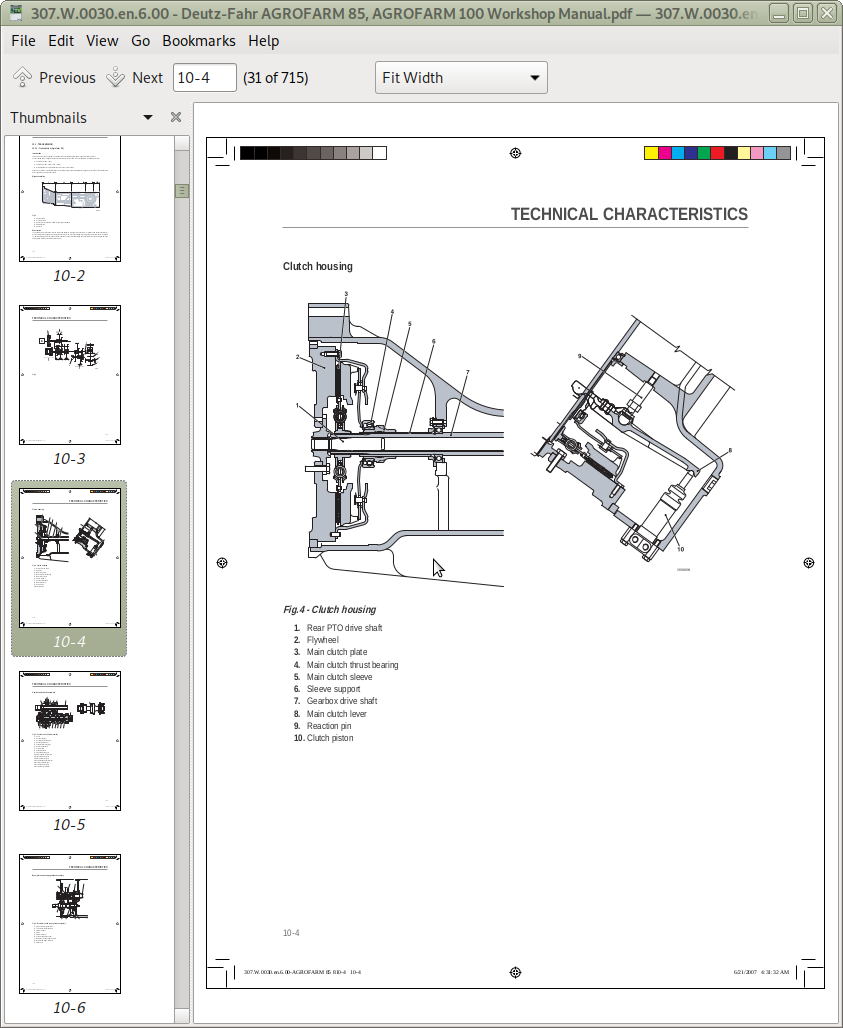
10 - TECHNICAL CHARACTERISTICS
10.1 - Transmission
10.1.1 - Transmission (Agrofarm 85)
10.1.2 - Transmission (Agrofarm 100)
10.1.3 - Rear. PTO
10.1.4 - 2 and 4-speed PTO and groundspeed PTO
10.2 - Front axle
10.2.1 - Front axle
10.3 - Hydraulic system
10.3.1 - Hydraulic system (Agrofarm 85)
10.3.2 - Hydraulic system (Agrofarm 100)
10.3.3 - Steering circuit pump - directional control valve circuit
10.3.4 - Power steering
10.3.5 - Auxiliary services directional control valve
10.3.6 - Hydraulic lift directional control valve (Agrofarm 85)
10.3.7 - Hydraulic lift directional control valve (Agrofarm 100)
10.3.8 - Braking system
10.3.9 - “Separate-Brake” valve
10.3.10 - Trailer braking valve
10.3.11 - Services solenoid valve assembly
20 - CALIBRATIONS AND ELECTRONIC DIAGNOSIS
20.1 - Diagnostic instrument
20.1.1 - All Round Tester
20.1.2 - Connecting the tester to the lift and engine control units
20.2 - Introduction to the tractor≈s electronic system
20.2.1 - Introduction to the tractor’s electronic system
20.3 - Putting the tractor into service
20.3.1 - Putting the tractor into service
20.4 - ECU alarms
20.4.1 - Instrument panel alarms
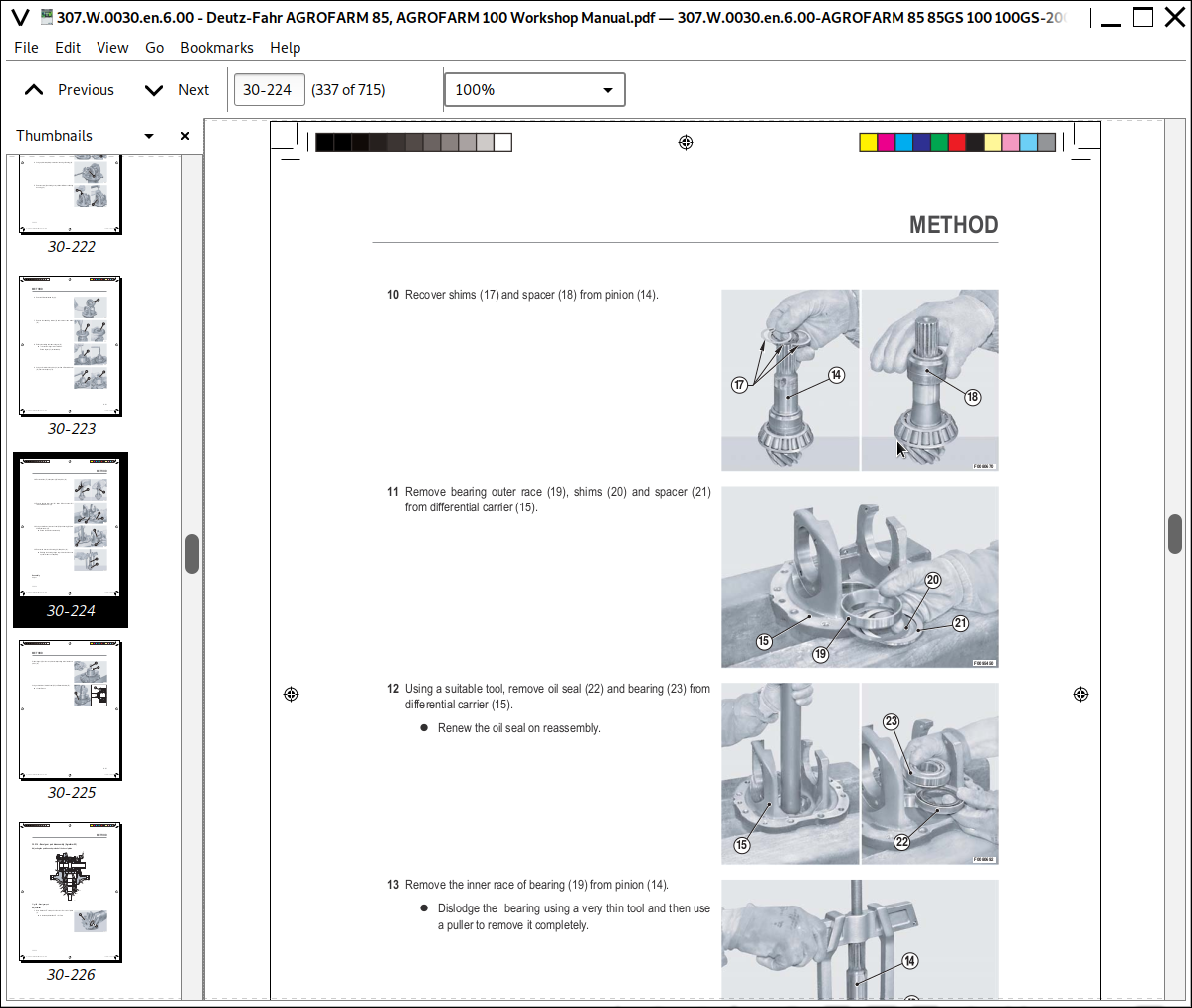
30 - METHOD
30.1 - Engine
30.1.1 - Engine - Separation from the transmission (B0.00.02)
30.1.2 - Engine (B0.00.01)
30.1.3 - Fan belt
30.1.4 - Tensioning the fan drive belt
30.1.5 - Alternator and fuel pump drive belt
30.1.6 - Alternator and fuel pump belt tensioning
30.2 - Engine accessories
30.2.1 - RADIATOR - Tractor without front PTO (C0.01.01)
30.2.2 - RADIATOR - Tractor with front PTO (C0.01.01)
30.2.3 - Changing the coolant and fl ushing the circuit
30.2.4 - Fuel tank (C0.03.01)
30.2.5 - Starter motor
30.2.6 - Exhaust pipe - Tractor with cab (C0.06.01)
30.3 - Transmission
30.3.1 - Parking brake
30.3.2 - Clutch plate
30.3.3 - Clutch thrust bearing
30.3.4 - Clutch housing - assembly (D0.02.01) (Agrofarm 85)
30.3.5 - Clutch housing - assembly (D0.02.01) (Agrofarm 100)
30.3.6 - Gearbox and shuttle assy. - complete unit (D0.09.03)
30.3.7 - Disassembly of gearbox and shuttle assy. - complete unit
30.3.8 - Gearbox support and gear selector rods
30.3.9 - Shuttle shaft
30.3.10 - Primary shaft
30.3.11 - Secondary shaft (Agrofarm 85)
30.3.12 - Secondary shaft (Agrofarm 100)
30.3.13 - PTO output shaft (4 speed version)
30.3.14 - PTO output shaft disassembly (4 speed version)
30.3.15 - PTO output shaft (2 speed version)
30.3.16 - PTO output shaft disassembly (2 speed versions)
30.3.17 - PTO clutch
30.3.18 - PTO clutch disassembly
30.3.19 - PTO fi nal shaft (2-speed version)
30.3.20 - PTO fi nal shaft (4-speed version)
30.3.21 - Groundspeed PTO fi nal shaft
30.3.22 - Groundspeed PTO engagement device
30.3.23 - Range and differential assembly - complete assembly
30.3.24 - Rear pinion (Agrofarm 85)
30.3.25 - Rear pinion (Agrofarm 100)
30.3.26 - Four-wheel drive output shaft
30.3.27 - Differential - Bevel gear pair
30.3.28 - Range selector assembly
30.3.29 - Changing transmission oil (D0.00.01)
30.3.30 - Pump drive PTO - Outer gear
30.3.31 - Pump drive PTO - Inner gear
30.3.32 - 4WD engagement device
30.4 - Rear axle
30.4.1 - RH rear axle (E0.02.01) (Agrofarm 85)
30.4.2 - LH rear axle (E0.02.02) (Agrofarm 85)
30.4.3 - RH/LH rear axle (Agrofarm 85)
30.4.4 - RH rear axle (Agrofarm 100)
30.4.5 - Planet carrier assembly (Agrofarm 85)
30.4.6 - LH rear axle (Agrofarm 100)
30.4.7 - RH/LH rear axle (Agrofarm 100)
30.4.8 - Planet carrier assembly (Agrofarm 100)
30.4.9 - Rear differential
30.4.10 - Rear differential disassembly (Agrofarm 85)
30.4.11 - Rear differential disassembly (Agrofarm 100)
30.4.12 - Rear axle brake discs
30.4.13 - Rear axle brake piston (Agrofarm 85)
30.4.14 - Rear axle brake piston (Agrofarm 100)
30.5 - Front axle
30.5.1 - Front carrier (F0.01.01)
30.5.2 - 4WD front axle (F0.03.01)
30.5.3 - Adjusting the front axle end fl oat
30.5.4 - Steering cylinders
30.5.5 - Steering cylinders disassembly
30.5.6 - Final drive reduction unit
30.5.7 - Final drive reduction unit disassembly
30.5.8 - Steering knuckle housing and halfshaft
30.5.9 - Steering knuckle housing and halfshaft
30.5.10 - Differential unit
30.5.11 - Differential disassembly
30.5.12 - Differential unit adjustment
30.5.13 - Bevel gear pair (Agrofarm 85)
30.5.14 - Bevel gear pair disassembly (Agrofarm 85)
30.5.15 - Differential disassembly (Agrofarm 85)
30.5.16 - Bevel gear pair (Agrofarm 100)
30.5.17 - Bevel gear pair disassembly (Agrofarm 100)
30.5.18 - Differential disassembly (Agrofarm 100)
30.5.19 - Front brake discs
30.5.20 - Front axle brake piston
30.5.21 - 4WD shaft
30.6 - Bodywork - Cab - Platform
30.6.1 - Cab (G0.03.01)
30.6.2 - Front hoods (G0.01.01)
30.6.3 - Fenders
30.6.4 - Front instrument panel (G0.06.04)
30.6.5 - Air conditioning
30.6.6 - Compressor
30.6.7 - Clutch master cylinder
30.6.8 - Clutch piston
30.6.9 - Clutch control circuit
30.6.10 - Brake master cylinders
30.6.11 - Control levers (Agrofarm 85)
30.6.12 - Control levers (Agrofarm 100)
30.7 - Hydraulic system
30.7.1 - Pump for hydraulic lift and auxiliary services
30.7.2 - Power steering (H0.02.01)
30.7.3 - Pressure relief valve setting:
30.7.4 - Power steering disassembly
30.7.5 - Power steering pump
30.7.6 - Rear 4-way auxiliary services control valve (Agrofarm 85)
30.7.7 - Rear 6-way auxiliary services control valve (Agrofarm 100)
30.7.8 - Braking circuit (Agrofarm 85)
30.7.9 - Braking circuit (Agrofarm 100)
30.7.10 - Services solenoid valve assembly
30.8 - Front PTO
30.8.1 - Front PTO
30.8.2 - PTO assembly.
30.8.3 - Pump assy
30.8.4 - Clutch-brake assembly
30.8.5 - Solenoid valve assy
30.9 - Front lift
30.9.1 - Front lift
30.9.2 - Lift cylinders
30.10 - Rear lift
30.10.1 - Lift - Complete assembly (R0.02.03) (Agrofarm 85)
30.10.2 - Lift disassembly - complete assembly (Agrofarm 85)
30.10.3 - Lift - Complete assembly (R0.02.03) (Agrofarm 100)
30.10.4 - Lift disassembly - Complete assembly (Agrofarm 100)
30.10.5 - Lift cylinder (Agrofarm 100)
30.10.6 - Bushes (Agrofarm 100)
30.10.7 - Hydraulic lift directional control valve (Agrofarm 85)
30.10.8 - Lift control valve disassembly (Agrofarm 85)
30.10.9 - Lift control valve disassembly (Agrofarm 100)
30.10.10 - Mechanical draft sensor (Agrofarm 85)
30.10.11 - Mechanical draft sensor disassembly (Agrofarm 85)
30.10.12 - Mechanical draft sensor (Agrofarm 100)
30.10.13 - Mechanical draft sensor disassembly (Agrofarm 100)
30.10.14 - 3-point linkage
30.11 - Wheels
30.11.1 - Front wheels (S0.01.01)
30.11.2 - Rear wheels (S0.02.01)
30.12 - Ballast - Towing hitches
30.12.1 - Towing hitch slide (Agrofarm 85)
30.12.2 - Towing hitch slide (Agrofarm 100)
40 - WIRING DIAGRAMS
40.1 - Introduction
40.1.1 - Structure of the unit
40.1.2 - Wiring and components index
40.2 - Components
40.2.1 - Components
40.3 - Systems
40.3.1 - Earthing points
40.3.2 - Starting and pre-heating
40.3.3 - Lights selector - Tractor with cab
40.3.4 - Lights selector - Tractor with platform
40.3.5 - Diagnostic accessories - Tractor with standard cab
40.3.6 - Diagnostic accessories - Tractor with high-visibility cab
40.3.7 - Instrument panel
40.3.8 - Worklights - Tractor with standard cab
40.3.9 - Wipers - Tractor with standard cab
40.3.10 - Heating system - Tractor with standard cab
40.3.11 - Air conditioning system - Tractor with standard cab
40.3.12 - Worklights - Tractor with high-visibility cab
40.3.13 - Wipers - Tractor with high-visibility cab
40.3.14 - Heating system - Tractor with high-visibility cab
40.3.15 - Air conditioning system - Tractor with high-visibility cab
40.3.16 - Transmission
40.3.17 - PTO
40.3.18 - Brakes
40.3.19 - CAN BUS ELECTRONIC SYSTEM
40.4 - Wiring looms
40.4.1 - Hood lights wiring - 0.014.8107.4/20
40.4.2 - Hood lights wiring connector positions
40.4.3 - Engine wiring - version with front battery - 0.014.8629.4/20
40.4.4 - Engine wiring connector positions - version with front battery
40.4.5 - Engine wiring - version with lateral battery - 0.015.1597.4/10
40.4.6 - Engine wiring connector positions - version with lateral battery
40.4.7 - Battery wiring loom - 0.014.8806.4/20
40.4.8 - Battery wiring connector positions
40.4.9 - Preheating wiring loom - 0.014.9195.4/20
40.4.10 - Pre-heating wiring connector positions
40.4.11 - Power supply wiring - 0.015.1983.4/10
40.4.12 - Power supply wiring connector positions
40.4.13 - Instrument panel wiring - 0.014.8628.4/20
40.4.14 - Instrument panel wiring connector positions
40.4.15 - RH drivetrain wiring - 0.014.8630.4/20
40.4.16 - RH drivetrain wiring connector positions
40.4.17 - LH drivetrain wiring - 0.014.9193.4/20
40.4.18 - LH drivetrain wiring connector positions
40.4.19 - Power supply wiring - Tractor with standard cab - 0.014.9375.4/20
40.4.20 - Power supply wiring connector positions - Tractor with standard cab
40.4.21 - Roof line wiring - Tractor with standard cab - 0.009.7850.4/50
40.4.22 - Roof line wiring connector positions - Tractor with standard cab
40.4.23 - Heating wiring - Tractor with standard cab - 0.010.2147.2
40.4.24 - Heating system wiring connector positions - Tractor with standard cab
40.4.25 - Air conditioning wiring - Tractor with standard cab - 0.010.2153.2
40.4.26 - Air conditioner wiring connector positions - Tractor with standard cab
40.4.27 - Air conditioning cooler fan wiring - Tractor with standard cab - 0.009.7853.3/20
40.4.28 - Air conditioner exchanger fan wiring connector positions - Tractor with standard cab
40.4.29 - Front-rear worklights wiring - Tractor with standard cab - 0.009.7851.4/50
40.4.30 - Supplementary worklights wiring connector positions - Tractor with standard cab
40.4.31 - Supplementary worklights wiring - Tractor with standard cab - 0.015.1435.4/10
40.4.32 - Supplementary worklights wiring connector positions - Tractor with standard cab
40.4.33 - Windscreen wiper wiring - Tractor with standard cab - 0.010.4516.3
40.4.34 - Windscreen wiper connector positions wiring - Tractor with standard cab
40.4.35 - Loudspeaker wiring - Tractor with standard cab - 0.011.0729.4/10
40.4.36 - Loudspeaker wiring connector positions - Tractor with standard cab
40.4.37 - Cab power supply wiring - Tractor with high-visibility cab - 0.014.9376.4/10
40.4.38 - Cab power supply wiring connector positions - Tractor with high-visibility cab
40.4.39 - Roof line wiring - Tractor with high-visibility cab - 0.011.3606.4/50
40.4.40 - Roof line wiring connector positions - Tractor with high-visibility cab
40.4.41 - Heating system wiring - Tractor with high-visibility cab - 0.010.2554.2
40.4.42 - Heating system wiring connector positions - Tractor with high-visibility cab
40.4.43 - Air conditioning wiring - Tractor with high-visibility cab - 0.010.2560.0
40.4.44 - Air conditioner wiring connector positions - Tractor with high-visibility cab
40.4.45 - Air conditioning cooler fan wiring - Tractor with high-visibility cab - 0.011.3610.3/20
40.4.46 - Air conditioning exchanger fan wiring connector positions - Tractor with high-visibility
cab
40.4.47 - Front-rear worklights wiring - Tractor with high-visibility cab - 0.011.3595.3/10
40.4.48 - Worklights wiring connector positions - Tractor with high-visibility cab
40.4.49 - Supplementary worklights wiring - Tractor with high-visibility cab - 0.015.1437.4/10
40.4.50 - Supplementary worklights wiring connector positions - Tractor with high-visibility cab
40.4.51 - Windscreen wiper wiring - Tractor with high-visibility cab - 0.011.3597.3
40.4.52 - Windscreen wiper wiring connector positions - Tractor with high-visibility cab
40.4.53 - Loudspeaker, radio, rear wiper, fl ashing light and clock wiring - Tractor with high-
visibility cab - 0.011.3596.3/40
40.4.54 - Loudspeaker, radio, rear wiper, fl ashing light and clock wiring connector positions
- Tractor with high-visibility cab
40.4.55 - Wiring for front lights - Tractor with cab - 0.010.8189.3/40
40.4.56 - Front lights wiring connector positions - Tractor with cab
40.4.57 - Wiring for lower front lights - Tractor with cab - 0441.1923.4
40.4.58 - Lower front lights wiring connector positions - Tractor with cab
40.4.59 - Wiring for front lights - Tractor with platform - 0.015.3094.4
40.4.60 - Front lights wiring connector positions - Tractor with platform
40.4.61 - Worklights wiring - Tractor with platform - 0.014.9281.4
40.4.62 - Worklights wiring connector positions - Tractor with platform
40.4.63 - Rotating beacon wiring - 0.012.9909.4
40.4.64 - Position of rotary beacon wiring connectors
40.4.65 - Trailer hydraulic braking wiring - 0.014.1645.4/10
40.4.66 - Trailer hydraulic braking wiring connector positions
Deutz-Fahr AGROFARM 85, AGROFARM 100 Service Manual
![]()