
John Deere 310E Backhoe Loader Service Repair Manual (TM1649)
Complete repair technical manual for John Deere 310E Backhoe Loader, with all the workshop information to maintain, repair, and rebuild like professional mechanics.
John Deere 310E Backhoe Loader workshop service repair manual includes:
* Numbered table of contents easy to use so that you can find the information you need fast.
* Detailed sub-steps expand on repair procedure information
* Numbered instructions guide you through every repair procedure step by step.
* Notes, cautions and warnings throughout each chapter pinpoint critical information.
* Bold figure number help you quickly match illustrations with instructions.
* Detailed illustrations, drawings and photos guide you through every procedure.
* Enlarged inset helps you identify and examine parts in detail.
tm1649 - John Deere 310E Backhoe Loader Technical Manual - Repair.pdf
tm1649 - John Deere 310E Backhoe Loader Technical Manual - Repair.epub
Total Pages: 914 pages
File Format: PDF/EPUB/MOBI/AZW (PC/Mac/Android/Kindle/iPhone/iPad; bookmarked, ToC, Searchable, Printable)
Language: English
MAIN SECTIONS
Foreword
HELP!! HELP!! HELP!! HELP!!
General Information
Safety Information
General Specifications
Torque Values
Fuels and Lubricants
Wheels
Powered or Non-Powered Wheels and Fastenings
Axles and Suspension Systems
Input Drive Shafts and U-Joints
Non-Powered Wheel Axles
Powered Wheel Axle (MFWD)
Axle Shaft, Bearings and Reduction Gears
Dealer Fabricated Tools
Transmission
Removal and Installation
Controls Linkage
Input Drive Shafts and U-Joint
Gears, Shafts, Bearings, and Power Shift Clutch
Hydraulic System
Dealer Fabricated Tools
Engine
Removal and Installation
Dealer Fabricated Tools
Engine Auxiliary Systems
Cold Weather Starting Aid
Cooling Systems
Speed Controls
Intake System
Exhaust System
External Fuel Supply System
Torque Converter
Turbine, Gears and Shaft
Steering System
Hydraulic System
Service Brakes
Active Elements
Hydraulic System
Park Brake
Active Elements
Electrical Systems
Batteries, Support, and Cables
Alternator, Regulator and Charging System Wiring
Lighting System
Wiring Harness and Switches
System Controls
Instruments and Indicators
Motors and Actuators
Frames, Chassis Or Supporting Structure
Frame Installation
Chassis Weights
Operator’s Station
Removal and Installation
Operator Enclosure
Seat and Seat Belt
Heating and Air Conditioning
Dealer Fabricated Tools
Sheet Metal and Styling
Hood and Engine Enclosure
Miscellaneous Shields
Grille and Grille Housing
Fenders
Safety, Convenience, and Miscellaneous
Radio
Horn and Warning Devices
Main Hydraulic System
Hydraulic System
Loader
Loader
Bucket
Control Linkages
Hydraulic System
Backhoe
Bucket
Control Linkage
Frames
Hydraulic System
tm1649 - 310E Backhoe Loader
Table of Contents
Foreword
Technical Information Feedback Form
Section 00: General Information
Group 0001: Safety Information
Handle Fluids Safely—Avoid Fires
Prevent Battery Explosions
Prepare for Emergencies
Prevent Acid Burns
Handle Chemical Products Safely
Avoid High-Pressure Fluids
Park Machine Safely
Support Machine Properly
Wear Protective Clothing
Work in Clean Area
Service Machines Safely
Work In Ventilated Area
Illuminate Work Area Safely
Replace Safety Signs
Use Proper Lifting Equipment
Remove Paint Before Welding or Heating
Avoid Heating Near Pressurized Fluid Lines
Keep ROPS Installed Properly
Service Tires Safely
Practice Safe Maintenance
Use Proper Tools
Decommissioning — Proper Recycling and Disposal of Fluids and Components
Live With Safety
Group 0002: General Specifications
310E Backhoe Loader Dimensions
310E Backhoe Loader Specifications
Other Information—310E Backhoe Loader
310E Backhoe Loader Weight
310E Buckets
310E Backhoe Loader Drain and Refill Capacities
310E Backhoe Loader Lifting Capacities—Standard Dipperstick
310E Backhoe Loader Lifting Capacities—Extendible Dipperstick (Retracted)
310E Backhoe Loader Lifting Capacities—Extendible Dipperstick (Extended)
Group 0003: Torque Values
Hardware Torque Specifications
ROPS Torque Specifications
Metric Bolt and Screw Torque Values
Additional Metric Cap Screw Torque Values
Unified Inch Bolt and Screw Torque Values
O-Ring Groove Connections
Check Oil Lines And Fittings
Service Recommendations for O-Ring Boss Fittings
Service Recommendations for Flat Face O-Ring Seal Fittings
Service Recommendations for Metric Series Four Bolt Flange Fitting
Service Recommendations For Inch Series Four Bolt Flange Fittings
Group 0004: Fuels and Lubricants
Diesel Fuel
Low Sulfur Diesel Fuel Conditioner
Handling and Storing Diesel Fuel
Do Not Use Galvanized Containers
Diesel Engine Coolant (engine with wet sleeve cylinder liners)
Fuel Tank
Diesel Engine Oil — Non-Emissions Certified and Certified Tier 1 and Stage I
Transmission, Axle, and Mechanical Front Wheel Drive Oil
Hydraulic Oil
Grease
Grease for Extendible Dipperstick, Sideshift Frame, and Stabilizer Leg Wear Strips
Alternative and Synthetic Lubricants
Lubricant Storage
Mixing of Lubricants
Section 01: Wheels
Group 0110: Powered or Non-Powered Wheels and Fastenings
Service Equipment and Tools
Specifications
Remove and Install Rear Wheel Assembly
Remove and Install Front Wheel Assembly
Remove and Install Tire
Section 02: Axles and Suspension Systems
Group 0225: Input Drive Shafts and U-Joints
Specifications
Remove and Install Drive Shaft
Replace Drive Shaft U-Joints
Group 0230: Non-Powered Wheel Axles
Service Equipment and Tools
Other Material
Specifications
Remove and Install Hub Assembly
Remove and Install Spindle and Knuckle Assembly
Remove and Install Tie Rod
Remove and Install Non-Powered Front Axle
Adjust Non-Powered Front Axle Toe-In
Group 0240: Powered Wheel Axle (MFWD)
Service Equipment and Tools
Other Material
Specifications
Mechanical Front Wheel Drive Axle (MFWD) Disassemble and Assemble
Remove and Install Powered Front Axle
Adjust MFWD Axle Toe-In
Group 0250: Axle Shaft, Bearings and Reduction Gears
Essential Tools
Service Equipment and Tools
Other Material
Specifications
Remove and Install Rear Axle
Inspect Service Brakes
Disassemble Rear Axle
Park Brake Disassemble and Assemble
Assemble Rear Axle
Check Service Brakes After Assembly
Check Gear Tooth Contact Pattern
Group 0299: Dealer Fabricated Tools
DFT1146 Axle Mounting Bracket
DFT1147 Axle Rolling Torque Bar
Section 03: Transmission
Group 0300: Removal and Installation
Specifications
Remove and Install Transmission
Group 0315: Controls Linkage
Other Material
Specifications
Remove and Install Reverser Control
Remove and Install Transmission Shift Lever
Shift Lever and Housing Remove
Disassemble and Assemble Shift Lever and Housing
Shift Lever and Housing—Install
Group 0325: Input Drive Shafts and U-Joint
Specifications
Drive Shaft—Remove and Install
Replace Drive Shaft U-Joints
Group 0350: Gears, Shafts, Bearings, and Power Shift Clutch
Essential Tools
Service Equipment and Tools
Other Material
Specifications
Remove Outer Components to Disassemble Transmission
Disassemble Converter Side of Case
Oil Suction Tube—Remove
Clutch Packs Reverse and Forward—Remove
Disassemble and Assemble Reverse or Forward Clutch Pack
Transmission Drive Shaft—Remove
Transmission Drive Shaft—Disassemble and Assemble
Rear Output Shaft with Synchronizer—Remove
Intermediate Shaft with Synchronizer—Remove
Rear Output and Intermediate Shaft with Synchronizer—Disassemble
Rear Output Shaft—Cross Section View
Intermediate Shaft—Cross Section View
Rear Output and Intermediate Shaft with Synchronizer—Assemble
MFWD Output Shaft Remove (If Equipped)
MFWD Shaft—Disassemble
MFWD Shaft—Cross Section View
MFWD Shaft—Assemble
Idler Shaft—Remove Disassemble and Assemble
Oil Supply Tube—Remove and Install
Idler and MFWD Shafts—Install
Intermediate and Rear Output Shafts—Install
Drive Shaft—Install
Reverse and Forward Clutch Packs Install
Oil Suction Tube—Install
Transmission Case Converter Side—Assemble
Install Outer Components to Assemble Transmission
Group 0360: Hydraulic System
Other Material
Specifications
Remove and Install Control Valve
Disassemble and Assemble Control Valve
Remove and Install Transmission Charge Pump
Transmission Charge Pump—Disassemble and Assemble
Manifold Plate Solenoids—Remove and Install
Group 0399: Dealer Fabricated Tools
DFT1143 Transmission Support Bracket
Section 04: Engine
Group 0400: Removal and Installation
Essential Tools
Specifications
PowerTech 4.5 L (4045) John Deere Engine—Use CTM104
Remove And Install Engine
Group 0499: Dealer Fabricated Tools
DFT1145 Transmission Holding Bracket
Section 05: Engine Auxiliary Systems
Group 0505: Cold Weather Starting Aid
Specifications
Remove and Install Coolant Heater
Remove and Install Starting Aid Nozzle
Remove and Install Starting Aid Solenoid
Group 0510: Cooling Systems
Specifications
Remove and Install Fan
Remove and Install Fan Belt
Remove and Install Radiator
Group 0515: Speed Controls
Disassemble And Assemble Speed Control Linkage
Group 0520: Intake System
Essential Tools
Service Equipment and Tools
Specifications
Remove and Install Air Cleaner
Air Intake System Leakage Test
Group 0530: Exhaust System
Remove and Install Muffler—Without Altitude Compensator
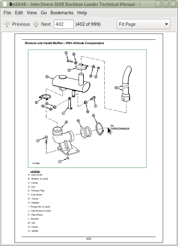
Remove and Install Muffler—With Altitude Compensator
Group 0560: External Fuel Supply System
Other Material
Specifications
Remove and Install Fuel Tank
Section 06: Torque Converter
Group 0651: Turbine, Gears and Shaft
Remove and Install Torque Converter
Disassemble and Assemble Torque Converter
Section 09: Steering System
Group 0960: Hydraulic System
Service Equipment and Tools
Other Material
Specifications
Remove and Install Steering Column
Disassemble and Assemble Tilt Steering Wheel and Column
Remove and Install Steering Valve
Disassemble Steering Valve
Cross Section of Steering Valve
Assemble Steering Valve
Remove and Install Non-Powered Axle Steering Cylinder
Disassemble Non-Powered Axle Steering Cylinder
Cross Section of Non-Powered Axle Steering Cylinder
Assemble Non-Powered Axle Steering Cylinder
Remove and Install Steering Cylinder Bushings
Cross Section of APL-2025 MFWD Axle Steering Cylinder
Exploded View of APL-2025 MFWD Axle Steering Cylinder
Disassemble and Assemble APL-2025 MFWD Axle Steering Cylinder
Adjust Tracking Angle for MFWD Axle
Remove and Install Priority Valve
Disassemble and Assemble Priority Valve
Section 10: Service Brakes
Group 1011: Active Elements
Inspect Service Brakes
Remove and Install Brake Disk and Pressure Plate
Group 1060: Hydraulic System
Other Material
Specifications
Remove and Install Brake Valve
Disassemble and Assemble Brake Valve
Disassemble and Assemble Brake Valve Lines
Adjust Brake Pedals
Bleeding Brakes
Section 11: Park Brake
Group 1111: Active Elements
Remove and Install Park Brake
Section 16: Electrical Systems
Group 1671: Batteries, Support, and Cables
Service Equipment and Tools
Specifications
Service Batteries Carefully
Procedure for Testing Batteries
Checking Electrolyte Specific Gravity
Check Battery Electrolyte Level and Terminals
Using Booster Batteries—12 Volt System
Charge Battery
Remove and Install Batteries
Group 1672: Alternator, Regulator and Charging System Wiring
Specifications
Bosch Alternator Repair—Use CTM77
Remove and Install Alternator
Group 1673: Lighting System
Remove and Install Drive and Work Light
Remove and Install Halogen Bulb
Remove and Install Display Module Bulbs
Remove and Install Turn, Brake, and Tail Light Bulbs
Remove and Install Front Turn Light Bulb
Group 1674: Wiring Harness and Switches
Essential Tools
Specifications
Remove and Install Cab Roof Harness and Components
Remove and Install Cab Side Console Harness and Components
Remove and Install Front Console Harness and Components
Remove and Install Engine Harness and Components
Remove and Install Blower Harness and Components
Remove and Install Radio Harness and Components
Remove and Install A/C Compressor Harness and Components
Remove and Install Auxiliary Flow Control Harness and Components
Remove and Install Ride Control Harness and Components
Fuse Specifications
Replace 16 Way Kostal Connector
Install Kostal Open-Barrel Contact
Replace DEUTSCH DEUTSCH is a trademark of Deutsch Co. Connectors
Install DEUTSCH DEUTSCH is a trademark of Deutsch Co. Contact
Replace WEATHER PACK WEATHER PACK is a trademark of Packard Electric. Connectors
Install WEATHER PACK WEATHER PACK is a trademark of Packard Electric. Contact
Remove Connector Body From Blade Terminals
Remove Blade Terminals From Fuse Block
Group 1675: System Controls
Remove and Install Return-To-Dig Switch
Group 1676: Instruments and Indicators
Other Material
Remove and Install Fuel Gauge Sender
Group 1677: Motors and Actuators
Starter Motor Repair—Use CTM77
Remove and Install Starting Motor
Remove and Install Starter Relay
Section 17: Frames, Chassis Or Supporting Structure
Group 1740: Frame Installation
Essential Tools
Specifications
Welding Repair of Major Structures
Remove and Install RIVNUT RIVNUT is a registered trademark of The BF Goodrich Co. (KREMNUT) Fasteners
Group 1749: Chassis Weights
Specifications
Remove and Install Counterweight
Remove and Install Frame Bumper
Section 18: Operator’s Station
Group 1800: Removal and Installation
Service Equipment and Tools
Specifications
Remove and Install Cab/ROPS
Group 1810: Operator Enclosure
Other Material
Specifications
Disassemble and Assemble Fixed Right Front Cab Window and Wiper Motor
Disassemble and Assemble Right Cab Door and Wiper Motor
Disassemble and Assemble Left Cab Door and Wiper Motor
Adjust Cab Right Door Latch and Hinges
Adjust Cab Left Door Latch and Hinges
Adjust Cab Door Handle Screw
Disassemble and Assemble Cab Side Windows
Adjust Cab Side Windows
Disassemble and Assemble Upper Rear Window and Wiper Motor
Adjust Upper Rear Window
Disassemble and Assemble Lower Rear Windows
Adjust Lower Rear Window
Remove and Install Windowpanes
Remove and Install Headliner
Remove and Install Cab Roof
Group 1821: Seat and Seat Belt
Specifications
Remove and Install Seat Assembly
Disassemble and Assemble Seat, Belt, and Arm Rest
Disassemble and Assemble Seat Slide, Swivel, and Lumbar Control Levers
Disassemble and Assemble Seat Swivel and Latch
Disassemble and Assemble Seat Suspension and Shock Absorber
Disassemble and Assemble Seat Base and Support
Disassemble and Assemble Air Seat Suspension (If Equipped)
Group 1830: Heating and Air Conditioning
Essential Tools
Service Equipment and Tools
Other Material
Specifications
Proper Refrigerant Handling
R134a Refrigerant Cautions
Refrigerant Hoses and Tubing Inspection
Refrigerant Theory of Operation
Remove and Install Air Conditioning Compressor
R134a Compressor Oil Removal
Disassemble and Assemble Compressor Clutch
Clutch Hub Clearance Check
Inspect Compressor Manifold
Disassemble, Inspect, and Assemble Compressor
R134a Component Oil Charge
R134a Refrigerant Recovery/Recycling and Charging Station Installation Procedure
Recover R134a System
Evacuate R134a System
Charge R134a System
R134a System Leak Testing
Remove and Install Heater Core
Remove and Install Evaporator
Remove and Install A/C Freeze Switch
Disassemble and Assemble Heater/Blower Assembly
Disassemble and Assemble Heater/Blower Assembly with Air Conditioning
Disassemble and Assemble Blower Assembly
Disassemble and Assemble Condenser
Disassemble and Assemble Air Ducts
Group 1899: Dealer Fabricated Tools
DFRW20 Compressor Holding Fixture
DFT1101 Cab and ROPS Lift Bracket
Section 19: Sheet Metal and Styling
Group 1910: Hood and Engine Enclosure
Disassemble and Assemble Hood and Engine Enclosure
Group 1913: Miscellaneous Shields
Disassemble and Assemble Battery Box
Group 1921: Grille and Grille Housing
Disassemble and Assemble Grille and Grille Housing
Group 1927: Fenders
Disassemble and Assemble Fenders
Disassemble and Assemble Fender Extensions
Section 20: Safety, Convenience, and Miscellaneous
Group 2001: Radio
Remove and Install Radio and Speakers
Remove and Install Antenna
Disassemble and Assemble Radio, Speakers, and Antenna
Group 2004: Horn and Warning Devices
Remove and Install Horn
Remove and Install Back-Up Alarm
Adjust Back-Up Alarm Volume
Section 21: Main Hydraulic System
Group 2160: Hydraulic System
Service Equipment and Tools
Other Material
Specifications
Remove and Install Hydraulic Pump
Disassemble, Inspect, and Assemble Hydraulic Pump
Remove and Install Hydraulic Filter
Remove and Install Reservoir
Disassemble and Assemble Reservoir
Remove and Install Hydraulic and Transmission Oil Coolers (Without Air Conditioning)
Remove and Install Hydraulic Oil Cooler (With Air Conditioning) Hi-Ambient
Section 31: Loader
Group 3100: Loader
Specifications
Remove Loader
Install Loader
Group 3102: Bucket
Specifications
Remove and Install Loader Bucket
Replace Welded Bucket Cutting Edges
Repair Cracked Cutting Edge
Remove and Install Cutting Edge
Disassemble and Assemble Multi-Purpose Bucket and Lines
Group 3115: Control Linkages
Service Equipment and Tools
Specifications
Loader Bucket Self-Leveling Linkage Indicator and Return-to-Dig Switch Adjustment
Loader Control Valve Linkage Adjustment
Remove and Install Loader Bucket Cylinder Linkage
Group 3160: Hydraulic System
Essential Tools
Service Equipment and Tools
Other Material
Specifications
Disassemble and Assemble Bucket Curl and Boom Raise Circuit Relief Valve
Disassemble and Assemble Auxiliary and Bucket Dump Relief Valve with Anti-Cavitation
Disassemble and Assemble Boom Anti-Cavitation Valve
Disassemble and Assemble Loader System Relief Valve
Remove and Install Loader Control Valve Relief Valves
Disassemble and Assemble Auxiliary Shut-off Plug
Remove and Install Loader Control Valve
Disassemble and Assemble Loader Control Valve
Loader Backhoe Stabilizer and Combo Valve Spool Seals Remove and Install
Disassemble and Assemble Loader Control Valve Inlet Section
Disassemble and Assemble Loader Bucket Section
Disassemble and Assemble Loader Boom Section
Disassemble and Assemble Loader Auxiliary Section
Remove and Install Loader Bucket Cylinder
Remove and Install Loader Boom Cylinders
Disassemble Loader Bucket and Boom Cylinders—120 Series
Cross Section of Loader Bucket and Boom Cylinder—120 Series
Assemble Loader Bucket and Boom Cylinder—120 Series
Exploded View of Multi-Purpose Bucket Cylinder—120 Series
Remove and Install Ride Control Valve— If Equipped
Disassemble and Assemble Ride Control Valve— If Equipped
Remove and Install Ride Control Valve Solenoid—If Equipped
Remove and Install Ride Control Accumulator—If Equipped
Charging the Ride Control Accumulator
Charging the Ride Control Accumulator—Procedure “A” (14.2 in. accumulator)
Charging the Ride Control Accumulator—Procedure “B” (17.2 in. accumulator)
Ride Control Accumulator Discharge Procedure
Section 33: Backhoe
Group 3302: Bucket
Service Equipment and Tools
Specifications
Remove and Install Bucket and Bucket Links
Remove and Install Bucket Tooth Shanks and Tips
Remove and Install Bucket Tooth Shank
Remove and Install Bucket Cutting Edge
Group 3315: Control Linkage
Other Material
Specifications
Remove and Install Backhoe Boom Swing Lock Control Lever and Linkage
Remove and Install Backhoe Boom Swing Lock Arms and Locking Pin
Remove and Install Backhoe Valve Linkage—Two Lever
Backhoe Valve Linkage Adjustment
Remove and Install Stabilizer Valve Linkage (S.N. —874257)
Remove and Install Stabilizer Valve Linkage (S.N. 874258—)
Stabilizer Valve Linkage Adjustment
Group 3340: Frames
Other Material
Specifications
Remove and Install Dipperstick
Remove and Install Boom
Remove and Install Swing Frame
Remove Extendible Dipperstick Extension
Install Extendible Dipperstick Extension
Group 3360: Hydraulic System
Essential Tools
Service Equipment and Tools
Other Material
Specifications
Remove and Install Backhoe Control Valve
Disassemble and Assemble Backhoe Control Valve
Disassemble and Assemble Backhoe System Relief Valve without Anti-Cavitation (S.N. 943226—)
Remove and Install Backhoe Circuit Relief and System Relief Valves
Disassemble and Assemble System Relief Valve
Disassemble and Assemble Circuit Relief Valve with Anti-Cavitation
Disassemble and Assemble Crowd Out, Bucket Curl, and Boom Raise Circuit Relief Valve
Disassemble and Assemble Flow Control Relief Valve—Earlier Machines
Disassemble and Assemble Flow Control Relief Valve—Later Machines
Disassemble and Assemble Auxiliary Shut-off Plug
Disassemble and Assemble Backhoe Priority Section
Disassemble and Assemble Backhoe Auxiliary Flow Section
Disassemble and Assemble Backhoe Swing Section
Disassemble and Assemble Backhoe Boom Section
Disassemble and Assemble Backhoe Bucket Section
Disassemble and Assemble Backhoe Crowd Section
Disassemble and Assemble Backhoe Extendible Dipperstick Section
Loader Backhoe Stabilizer and Combo Valve Spool Seals Remove and Install
Remove and Install Stabilizer Valve
Disassemble and Assemble Stabilizer Valve
Remove and Install Backhoe Bucket Cylinder—125 Series
Remove and Install Backhoe Crowd Cylinder—125 Series
Remove and Install Backhoe Boom Cylinder—125 Series
Remove and Install Swing Cylinder—120 Series
Remove and Install Stabilizer Cylinder—120 Series
Remove and Install Extendible Dipperstick Cylinder
Disassemble Boom, Bucket, and Crowd Cylinders—125 Series
Cross Section of Backhoe Bucket and Crowd Cylinders—125 Series
Cross Section of Backhoe Boom Cylinder—125 Series
Assemble Boom, Bucket, and Crowd Cylinders—125 Series
Indexing 125—Series Cylinders
Disassemble Swing and Stabilizer Cylinders—120 Series
Cross Section of Stabilizer Cylinder—120 Series
Cross Section of Swing Cylinder—120 Series
Assemble Swing and Stabilizer Cylinder—120 Series
Disassemble Extendible Dipperstick Cylinder
Cross Section of Extendible Dipperstick Cylinder
Assemble Extendible Dipperstick Cylinder
John Deere 310E Backhoe Loader Service Repair Manual (TM1649)
![]()