
John Deere 27D Excavator Technical Manual - Operation and Test (TM2355)
Complete Dianosis & Test service manual with Electrical Wiring Diagrams for John Deere 27D Excavator, with all the service information to maintain, diagnose, and service like professional mechanics.
John Deere 27D Mini Excavator workshop diagnostics test manual includes:
* Numbered table of contents easy to use so that you can find the information you need fast.
* Detailed sub-steps expand on repair procedure information
* Numbered instructions guide you through every repair procedure step by step.
* Troubleshooting and electrical service procedures are combined with detailed wiring diagrams for ease of use.
* Notes, cautions and warnings throughout each chapter pinpoint critical information.
* Bold figure number help you quickly match illustrations with instructions.
* Detailed illustrations, drawings and photos guide you through every procedure.
* Enlarged inset helps you identify and examine parts in detail.
TM2355 - John Deere 27D Excavator Technical Manual (Operation & Test).pdf
TM2355 - John Deere 27D Excavator Technical Manual (Operation & Test).epub
Total Pages: 500 pages
File Format: PDF/EPUB/MOBI/AZW (PC/Mac/Android/Kindle/iPhone/iPad; bookmarked, ToC, Searchable, Printable)
Language: English
MAIN SECTIONS
Foreword
Technical Information Feedback Form
General Information
Safety
Operational Checkout Procedure
Operational Checkout Procedure
Engine
Theory of Operation
Diagnostic Information
Tests
Electrical System
System Information
System Diagrams
Sub-System Diagnostics
References
Power Train
Theory of Operation
Diagnostic Information
Hydraulic System
Theory of Operation
Diagnostic Information
Tests
Heating and Air Conditioning
Theory of Operation
Diagnostic Information
Tests
tm2355 - 27D Excavator
Table of Contents
Foreword
Technical Information Feedback Form
Section 9000: General Information
Group 01: Safety
Recognize Safety Information
Follow Safety Instructions
Operate Only If Qualified
Wear Protective Equipment
Avoid Unauthorized Machine Modifications
Inspect Machine
Stay Clear of Moving Parts
Avoid High-Pressure Fluids
Avoid High-Pressure Oils
Work In Ventilated Area
Prevent Fires
Prevent Battery Explosions
Handle Chemical Products Safely
Decommissioning — Proper Recycling and Disposal of Fluids and Components
Prepare for Emergencies
Clean Debris from Machine
Add Cab Guarding for Special Uses
Use Steps and Handholds Correctly
Start Only From Operator's Seat
Use and Maintain Seat Belt
Prevent Unintended Machine Movement
Avoid Work Site Hazards
Keep Riders Off Machine
Avoid Backover Accidents
Avoid Machine Tip Over
Inspect and Maintain ROPS
Add and Operate Attachments Safely
Park and Prepare for Service Safely
Service Cooling System Safely
Remove Paint Before Welding or Heating
Make Welding Repairs Safely
Drive Metal Pins Safely
Section 9005: Operational Checkout Procedure
Group 10: Operational Checkout Procedure
Operational Checkout
Section 9010: Engine
Group 05: Theory of Operation
Engine Component Location
Engine Cooling System Operation
Engine Lubrication System Operation
Engine Fuel System Operation
Group 15: Diagnostic Information
Yanmar 3-Cylinder Engine Troubleshooting Manual
Engine Cranks But Will Not Start
Engine Misfires Or Runs Irregularly
Engine Does Not Develop Full Power
Engine Overheats
Coolant Temperature Too Low
Coolant in Oil or Oil in Coolant
Low Engine Oil Pressure
High Engine Oil Pressure
Engine Uses Too Much Oil
Engine Uses Too Much Fuel
Engine Emits Excessive White Exhaust Smoke
Engine Emits Excessive Black or Gray Exhaust Smoke
Fuel In Oil
Group 25: Tests
JT05801 Clamp-On Electronic Tachometer Installation
Engine Speed Check
Engine Speed Control Lever and Cable Adjustment
Fuel Injection Nozzle Check
Fuel Transfer Pump PressureTest
Injection Pump Timing Check and Adjustment
Fan Belt Tension Adjustment
Engine Valve Lash (Clearance) Check and Adjustment
Air Intake System Leakage Test
Cooling System Pressure Test
Radiator Cap Test
Engine Thermostat Test
Engine Compression Pressure Test
Engine Oil Pressure Test
Head Gasket Failure Check
Bleed Fuel System
Section 9015: Electrical System
Group 05: System Information
Electrical Diagram Information
Component Identification Table
Fuse (Blade-Type) Color Codes
Group 10: System Diagrams
Fuse Specifications
System Functional Schematic, Wiring Diagrams, and Component Locations Master Legend
System Functional Schematic
Battery and Power Cable (W6 and W7) Component Location
Main Harness (W8) Component Location
Main Harness (W8) Wiring Diagram
Platform Harness (W9) Component Location
Platform Harness (W9) Wiring Diagram
Engine Harness (W10) Component Location
Engine Harness (W10) Wiring Diagram
Heating and A/C Control Harness (W11) Component Location
Heating and A/C Control Harness (W11) Wiring Diagram
A/C Compressor Harness (W12) Component Location
A/C Compressor Harness (W12) Wiring Diagram
Cab Harness (W13) Component Location
Cab Harness (W13) Wiring Diagram
Boom Work Light Harness (W14) Component Location
Boom Work Light Harness (W14) Wiring Diagram
ROPS Work Light Harness (W15) Component Location
ROPS Work Light Harness (W15) Wiring Diagram
Auxiliary Function Control Harness (W19) Component Location
Auxiliary Function Control Harness (W19) Wiring Diagram
Group 15: Sub-System Diagnostics
Start Circuit Theory of Operation
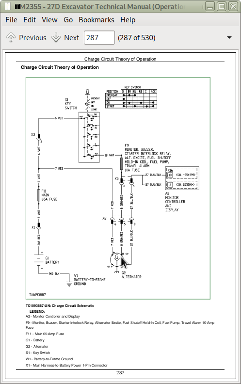
Charge Circuit Theory of Operation
Fuel Shutoff Circuit Theory of Operation
Monitor Controller Circuit Theory of Operation
Pilot Control Shutoff Circuit Theory of Operation
Travel Speed Control and Alarm Circuit Theory of Operation
Heating and Air Conditioning Control Circuit Theory of Operation
Preheating Circuit Theory of Operation
Auxiliary Function Control Lever Circuit Theory of Operation
Group 20: References
Alternator and Starting Motors
Electrical Component Specifications
Alternator Test
Relay Test
Pressure Sensor Test
Solenoid Test
Fuel Shutoff Circuit Test
Electrical Component Checks
Monitor Controller Remove and Install
Disconnect Tab Retainer Connectors
Disconnecting Spring Wire Clip Connectors
Replace Metri-Pack® (Push Type) Connectors
Replace Metri-Pack® Connectors
Replace DEUTSCH® Circular Connectors
Replace DEUTSCH® Rectangular or Triangular Connectors
Install DEUTSCH® Contact
Replace WEATHER PACK® Connector
Install WEATHER PACK® Contact
Replace CINCH™ Connectors
Install CINCH™ Contact
Repair 32 and 48 Way CINCH™ Connectors
Remove Connector Body from Blade Terminals
Section 9020: Power Train
Group 05: Theory of Operation
Track Adjuster and Recoil Spring Operation
Travel Gearbox Operation
Group 15: Diagnostic Information
Diagnose Undercarriage Components Malfunctions
Measure Swing Bearing Wear
Section 9025: Hydraulic System
Group 05: Theory of Operation
Hydraulic System Diagram
Pilot System Diagram
Pilot Pump Operation
Pilot Filter Operation
Solenoid Valve Manifold Operation
Pilot Control Valve Operation
Travel Pilot Control Valve Operation
Blade, Swing Boom, and Auxiliary Pilot Control Valve Operation
Hydraulic Pump 1 and 2 Operation
Hydraulic Pump Regulator Operation
Hydraulic Pump 3 and Pilot Pump Operation
A/C Torque Control Solenoid Valve Operation
Control Valve Operation
System Relief Valve Operation
Circuit Relief Valve Operation
Swing Boom Make-Up Check Valve Operation
Flow Combiner Valve Operation
Auxiliary Flow Combiner Valve Operation
Auxiliary Flow Selector Solenoid Valve Operation (Optional)
Auxiliary Function Control Valve Operation
Arm Regenerative Valve Operation
Swing Gearbox Operation
Swing Motor Operation
Swing Motor Crossover Relief Valve Operation
Swing Motor Make-Up Check Valve Operation
Swing Motor Park Brake Release Circuit Operation
Center Joint Operation
Travel Motor and Brake Valve Housing Operation
Travel Motor Speed Circuit Operation
Blade Circuit Operation
Auxiliary Selector Valve Operation—If Equipped
Hydraulic Cylinder Operation
Hydraulic Oil Return Filter Operation
Hydraulic System Circuit Symbols
Hydraulic System Schematics
Group 15: Diagnostic Information
Diagnostic Procedure
Diagnose Hydraulic System Malfunctions
Diagnose Pilot Circuit Malfunctions
Diagnose Dig Circuit Malfunctions
Diagnose Swing Circuit Malfunctions
Diagnose Travel System Malfunctions
Major Component Location
Main Hydraulic Pilot System Line Identification
Main Hydraulic Working System Line Identification
Blade Hydraulic System Line Identification
Travel Hydraulic System Line Identification
Pilot Control Valve to Pattern Selector Valve Line Connection
Group 25: Tests
Hydraulic Oil Cleanup Procedure Using Portable Filter Caddy
JT05800 Digital Thermometer Installation
JT02156A Digital Pressure/Temperature Analyzer Installation
Hydraulic System Warm-Up Procedure
Cylinder Drift Test—Boom, Arm, Bucket, and Blade
Pilot Pressure Regulating Valve Test and Adjustment
Control Valve Spool Pilot Actuating Pressure Test
Hydraulic Pumps 1, 2, and 3 System Relief Valve Test and Adjustment
Circuit Relief Valve Test and Adjustment
Swing Motor Crossover Relief Valve Test and Adjustment
Hydraulic Pumps 1 and 2 Regulator Test and Adjustment—Engine Pulldown
Hydraulic Pump 1 and 2 Flow Test
Hydraulic Pump 3 Flow Test
Swing Motor Leakage Test
Travel Motor Leakage Test
Section 9031: Heating and Air Conditioning
Group 05: Theory of Operation
Air Conditioning System Cycle Of Operation
Group 15: Diagnostic Information
Diagnose Air Conditioning System Malfunctions
Diagnose Heater System Malfunctions
Air Conditioner and Heater Component Location
Group 25: Tests
Refrigerant Cautions and Proper Handling
Air Conditioner and Heater Operational Checks
Refrigerant Leak Test
Air Conditioner Compressor Clutch Test
R134a Air Conditioning System Test
Operating Pressure Diagnostic Chart
John Deere 27D Excavator Technical Manual (Operation & Test) - TM2355
![]()