
John Deere Tractors 7220, 7320, 7420, 7520 Diagnosis and Tests Service Technical Manual (TM2047)
Complete Diagnosis & Tests Technical Manual with electrical wiring diagrams for John Deere 7220, 7320, 7420, 7520 2WD or MFWD Tractors, with all the workshop information to maintain, diagnose, and service like professional mechanics.
John Deere 2WD or MFWD Tractors 7220, 7320, 7420 and 7520 workshop Diagnosis & Tests technical manual includes:
* Numbered table of contents easy to use so that you can find the information you need fast.
* Detailed sub-steps expand on repair procedure information
* Numbered instructions guide you through every repair procedure step by step.
* Troubleshooting and electrical service procedures are combined with detailed wiring diagrams for ease of use.
* Notes, cautions and warnings throughout each chapter pinpoint critical information.
* Bold figure number help you quickly match illustrations with instructions.
* Detailed illustrations, drawings and photos guide you through every procedure.
* Enlarged inset helps you identify and examine parts in detail.
tm2047 - 7220, 7320, 7420 and 7520 Tractors Technical Manual - Operation & Tests.pdf
tm2047 - 7220, 7320, 7420 and 7520 Tractors Technical Manual - Operation & Tests.epub
PRODUCT DETAILS:
Total Pages: 6,648 pages
File Format: PDF/EPUB/MOBI/AZW (PC/Mac/Android/Kindle/iPhone/iPad; bookmarked, ToC, Searchable, Printable)
Language: English
MAIN SECTIONS
Foreword
SAFETY
Safety Measures
General References
DIAGNOSTIC TROUBLE CODES
ATC Diagnostic Trouble Codes
BCU Diagnostic Trouble Codes
BIF Diagnostic Trouble Codes
ECU Diagnostic Trouble Codes
EPC Diagnostic Trouble Codes
JDL Diagnostic Trouble Codes
PLC Diagnostic Trouble Codes
PRF Diagnostic Trouble Codes
SFA Diagnostic Trouble Codes
SIC Diagnostic Trouble Codes
SSU Diagnostic Trouble Codes
TCU Diagnostic Trouble Codes
TEC Diagnostic Trouble Codes
UIC Diagnostic Trouble Codes
OBSERVABLE SYMPTOMS
Engine
Electrical System
Transmission
Drive Systems
Steering and Brakes
Hydraulic System
Operator`s Cab
SYSTEM DIAGNOSTICS
Electronics
ENGINE
Additional Information
Operational Checkout
Checks and Adjustments
Theory of Operation
FUEL, AIR INTAKE AND COOLING SYSTEMS
Tests and Adjustments
Descriptions
ELECTRICAL SYSTEM
Sub-System Diagnostics
Sub-System Diagnostics (Open Operator`s Station)
Component Testing
Functional Schematics (AutoPowr / IVT Transmission)
Functional Schematics (PowrQuad-Plus Transmission)
Functional Schematics (Open Operator`s Station)
Wiring Harnesses
Wiring Harnesses from Serial No. 12451
ELECTRONIC CONTROL UNITS
General Operating Instructions and Diagnostic Information
Data Bus Systems –– Diagnostics
Data BUS Systems, Theory of Operation
ATC - Control Unit for ClimaTrak
BCU - Basic Control Unit
BIF - Basic Informator
ECU - Engine Control Unit
EPC - Control Unit for PowrQuad-Plus Transmission
JDL - Control Unit for JDLink
PLC - Park Lock Controller
PRF - Performance Monitor
SFA - Control Unit for MFWD Axle and Cab Suspension
SIC - E-SCV/E-ICV Controller
SSU - Control Unit for AutoTrac
TCU - Control Unit for AutoPowr / IVT Transmission
TEC - Tractor Equipment Controller
UIC - User Interface Controller
AutoPowr / IVT TRANSMISSION
Operational Checkout
Tests and Adjustments
Operation
PowrQuad and PowrQuad-Plus TRANSMISSIONS
Introductory Checks
Operational Checkout
Tests and Adjustments
Operation
DRIVE SYSTEMS
Operational Checks
Tests and Adjustments
Operation
STEERING AND BRAKES
Introductory Checks
Operational Checkout
Tests and Adjustments
Operation
HYDRAULIC SYSTEM
Operational Checkout
Tests and Adjustments
Theory of Operation
MFWD
Operational Checkout
Tests and Adjustments
Operation
OPERATOR`S CAB
Operational Checks
Tests and Adjustments
Theory of Operation
SPECIAL TOOLS (Dealer-Fabricated)
Special Tools (Dealer-Fabricated)
Special Tools and Test Equipment
tm2047 - 7220, 7320, 7420 and 7520 Tractors
Table of Contents
Foreword
Section 210: SAFETY
Group 05: Safety Measures
Recognize Safety Information
“Important” - Information
“Note” - Information
Prevent Machine Runaway
Avoid Harmful Asbestos Dust
Stay Clear of Rotating Drivelines
Handle Starting Fluid Safely
Handle Agricultural Chemicals Safely
Protect Against High Pressure Spray
Handle Fluids Safely—Avoid Fires
Prevent Battery Explosions
Prepare for Emergencies
Prevent Acid Burns
Avoid High-Pressure Fluids
Service Cooling System Safely
Remove Paint Before Welding or Heating
Avoid Heating Near Pressurized Fluid Lines
Work In Ventilated Area
Wear Protective Clothing
Practice Safe Maintenance
Park Machine Safely
Use Proper Lifting Equipment
Construct Dealer-Made Tools Safely
Support Machine Properly
Work in Clean Area
Illuminate Work Area Safely
Service Machines Safely
Use Proper Tools
Service Tires Safely
Service MFWD Tractor Safely
Keep ROPS Installed Properly
Replace Safety Signs
Dispose of Waste Properly
Live With Safety
Safety Measures on Electronic Control Units
Group 15: General References
Reference 210-15-001, General References—Summary
Reference 210-15-010, Unified Inch Bolt and Cap Screw Torque Values
Reference 210-15-015, Metric Bolt and Cap Screw Torque Values
Reference 210-15-020, Hydraulic System Inch Fitting Torque Values
Reference 210-15-025, Hydraulic System Metric Fitting Torque Values
Reference 210-15-030, Component Identification Table
Reference 210-15-035, How to Read a Functional Schematic
Reference 210-15-040, How to Read a Diagnostic Schematic
Reference 210-15-042, Wire Numbers and Color Codes
Reference 210-15-045, Schematic, Wiring and Harness Symbols
Reference 210-15-046, Troubleshooting Unsolved Problems
Reference 210-15-050, Visual Check of the Electrical System
Reference 210-15-055, Electrical Circuit Malfunctions
Reference 210-15-060, Seven Step Electrical Test Procedure
Reference 210-15-065, Hydraulic System — Circuit Symbols
Section 211: DIAGNOSTIC TROUBLE CODES
Group ATC: ATC Diagnostic Trouble Codes
Specifications
ATC 000170.03 - Sending Unit for Inside Air Temperature, Shorted or Open Circuit
ATC 000170.04 - Sending Unit for Inside Air Temperature, Short to Ground
ATC 000171.03 - Sending Units for Ambient Air Temperature, Shorted or Open Circuit
ATC 000171.04 - Sending Units for Ambient Temperature, Short to Ground
ATC 000628.12 - Controller, Internal Fault
ATC 000630.02 - Controller, Internal Fault
ATC 000639.14 - 29-bit CAN BUS, High Error Rate
ATC 000871.03 - Refrigerant Pressure Sending Unit, Shorted Circuit
ATC 000871.04 - Refrigerant Pressure Sending Unit, Grounded or Open Circuit
ATC 000876.03 - Air-Conditioning Relay, Shorted or Open Circuit
ATC 000876.04 - Air-Conditioning Relay, Grounded Circuit
ATC 000876.10 - Compressor Clutch Engages and Disengages Too Often
ATC 000876.14 - Compressor Switches Off Due to Engine Overheating
ATC 000919.04 - Solar Sensor Activated
ATC 000923.03 - Driver Unit for the Fan Motors, Shorted Circuit
ATC 000923.04 - Fan Motor Driver Unit, Grounded or Open Circuit
ATC 000923.12 - Fan Motors, Malfunction
ATC 001079.03 - 5-volt Power Supply, Shorted or Open Circuit
ATC 001079.04 - 5-volt Power Supply, Grounded Circuit
ATC 001546.03 - Potentiometer for Position of Water Valve, Shorted or Open Circuit
ATC 001546.04 - Potentiometer for Water Valve Position, Grounded Circuit
ATC 001547.03 - Sending Units for Evaporator Core Temperature, Shorted or Open Circuit
ATC 001547.04 - Sending Unit for Evaporator Core Temperature, Short to Ground
ATC 001548.03 - Sending Unit for Actual Outlet Air Temperature, Shorted or Open Circuit
ATC 001548.04 - Sending Unit for Actual Outlet Air Temperature, Grounded Circuit
ATC 001549.03 - Water Valve Motor, Shorted Circuit
ATC 001549.04 - Water Valve Motor, Grounded Circuit
ATC 001549.07 - Water Valve, Malfunction
ATC 001549.13 - Water Valve Not Calibrated
ATC 001552.03 - Temperature Control, Shorted or Open Circuit
ATC 001552.04 - Temperature Control, Grounded Circuit
ATC 001553.03 - Fan Speed Control, Shorted or Open Circuit
ATC 001553.04 - Fan Speed Control, Grounded Circuit
ATC 002000.09 - Engine Control Unit is not Transmitting any Data (Coolant Temperature)
ATC 523848.03 - Potentiometer for Position of Air Distribution Flaps, Shorted or Open Circuit
ATC 523848.04 - Potentiometer for Position of Air Distribution Flaps, Grounded Circuit
ATC 523848.05 - Adjusting Motor for Air Distribution, Shorted Circuit
ATC 523848.06 - Adjusting Motor for Air Distribution, Grounded Circuit
ATC 523848.07 - Air Distribution, Malfunction
ATC 523848.13 - Adjusting Motor for Air Distribution, Not Calibrated
ATC 523860.03 - Defog Sensor, Shorted or Open Circuit
ATC 523860.04 - Defog Sensor, Grounded Circuit
ATC 523860.02 - Defog Sensor, Frequency out of Valid Range
Group BCU: BCU Diagnostic Trouble Codes
Specifications
BCU 000070.31 - Handbrake Failure
BCU 000084.02 - Wheel Speed Sender, Circuit Fault
BCU 000168.16 - System Voltage Too High (Engine Running)
BCU 000168.17 - System Voltage Too Low (Idle Over 1500 rpm)
BCU 000168.18 - System Voltage Too Low (Idle Until 1500 rpm)
BCU 000186.02 - Rear PTO Speed Sender, Circuit Fault
BCU 000186.15 - Rear PTO Speed Registered After Switch-Off
BCU 000186.17 - Rear PTO Speed Not Registered
BCU 000190.02 - Engine Speed Sender, Circuit Fault
BCU 000629.12 - Control Unit, Internal Error
BCU 000639.12 - Control Unit, Internal Error
BCU 000639.13 - 29-bit CAN BUS, High Error Rate
BCU 000639.14 - 29-bit CAN BUS (Tractor BUS), Very High Error Rate
BCU 000639.19 - 29-bit CAN BUS, Very High Error Rate
BCU 000746.31 - Differential Lock Solenoid Valve, Circuit Fault
BCU 000980.07 - Rear PTO, Switch Error
BCU 001676.31 - Relay for LTC Coolant Pump, Circuit Fault
BCU 001882.02 - Front PTO Speed Sender, Circuit Fault
BCU 001882.15 - Front PTO Speed Registered After Switch-Off
BCU 001882.17 - Front PTO Speed Not Registered
BCU 001893.07 - Front PTO, Switch Error
BCU 299780.07 - Malfunction at Turn Signal Switch
BCU 302001.31 - INFORMATION FOR OPERATOR: 250-Hour Service
BCU 302002.31 - INFORMATION FOR OPERATOR: 500-Hour Service
BCU 302003.31 - INFORMATION FOR OPERATOR: 750-Hour Service
BCU 302004.31 - INFORMATION FOR OPERATOR: 1500-Hour Service
BCU 302071.31 - INFORMATION FOR OPERATOR: Turn Off the Rear PTO Switch
BCU 302073.31 - Rear PTO Solenoid, Circuit Fault
BCU 302077.31 - INFORMATION FOR OPERATOR: Sit on Seat or Turn Off the Rear PTO
BCU 302080.31 - Differential Lock, Switch Error
BCU 302082.31 - INFORMATION FOR OPERATOR: Actuate the MFWD Switch
BCU 302085.31 - MFWD, Switch Error
BCU 302086.31 - MFWD Clutch Solenoid, Circuit Fault
BCU 302087.31 - INFORMATION FOR OPERATOR: Tractor is Moving Although Handbrake is On
BCU 302088.31 - INFORMATION FOR OPERATOR: Handbrake is On and a Gear is Selected
BCU 302089.31 - INFORMATION FOR OPERATOR: Turn Off the Rear PTO Switch
BCU 302106.31 - Control Unit, Internal Error
BCU 302120.31 - Front PTO Solenoid Valve, Circuit Fault
BCU 302122.31 - Air Brake Solenoid Valve, Circuit Fault
BCU 302123.31 - Forward/Reverse Switch Signal Doesn't Match Signal of Not-Neutral Switch
BCU 302124.31 - Alternator Relay, Circuit Fault
BCU 302131.31 - Fault in Turn Signal Circuit
BCU 302132.31 - Hazard Warning Light Fuse F03/03 and/or F03/04 Defective
BCU 302133.31 - Rear PTO Preselector, Switch Error
BCU 302134.31 - HMS Program Switch Defective
BCU 302135.31 - Rear PTO Remote Control, Switch Error Left
BCU 302136.31 - Rear PTO Remote Control, Switch Error Right
BCU 302139.31 - INFORMATION FOR OPERATOR: Rear PTO can now be Switched On at the Remote Control Switch
BCU 302240.31 - Control Unit Connected to Wrong Wiring Harness Connector
BCU 303027.31 - Calibration of Hitch Control Unit Not Successful
BCU 303028.31 - Hitch Control Unit Not Calibrated
BCU 303037.03 - 5-Volt Supply Voltage Too High
BCU 303037.04 - 5-Volt Supply Voltage Too Low
BCU 303041.02 - Stepper Motor Coil 1, Open Lead
BCU 303042.02 - Stepper Motor Coil 2, Open Lead
BCU 303043.02 - Stepper Motor Coil 1, Circuit Fault
BCU 303044.02 - Stepper Motor Coil 2, Circuit Fault
BCU 303045.04 - System Voltage Too Low
BCU 303047.03 - System Voltage Too High
BCU 303049.02 - Conflicting Signals from Quick Raise/Lower Switch and Remote Switch
BCU 303049.03 - Rocker Switch for Quick Withdrawal, Signal Voltage Too High
BCU 303049.04 - Rocker Switch for Quick Withdrawal, Signal Voltage Too Low
BCU 303051.03 - Left Draft Sender, Signal Voltage Too High
BCU 303051.04 - Left Draft Sender, Signal Voltage Too Low
BCU 303052.03 - Right Draft Sender, Signal Voltage Too High
BCU 303052.04 - Right Draft Sender, Signal Voltage Too Low
BCU 303053.03 - Sensitivity Potentiometer, Signal Voltage Too High
BCU 303053.04 - Sensitivity Potentiometer, Signal Voltage Too Low
BCU 303054.03 - Hitch Height Control Potentiometer, Signal Voltage Too High
BCU 303054.04 - Hitch Height Control Potentiometer, Signal Voltage Too Low
BCU 303055.03 - Position Sender, Signal Voltage Too High
BCU 303055.04 - Position Sender, Signal Voltage Too Low
BCU 303056.03 - Raise Limit Potentiometer, Signal Voltage Too High
BCU 303056.04 - Raise Limit Potentiometer, Signal Voltage Too Low
BCU 303057.03 - Rate of Drop Potentiometer, Signal Voltage Too High
BCU 303057.04 - Rate of Drop Potentiometer, Signal Voltage Too Low
BCU 303058.02 - Remote Control Switch, Erroneous Signal
BCU 303060.02 - Stepper Motor Deadband Out of Range
BCU 303177.18 - Oil Temperature During Calibration Too Low
BCU 303251.02 - Left Draft Sender, Disrupted Signal During Calibration
BCU 303251.03 - Left Draft Sender, Signal Voltage Too High During Calibration
BCU 303251.04 - Left Draft Sender, Signal Voltage Too Low During Calibration
BCU 303252.02 - Right Draft Sender, Disrupted Signal During Calibration
BCU 303252.03 - Right Draft Sender, Signal Voltage Too High During Calibration
BCU 303252.04 - Right Draft Sender, Signal Voltage Too Low During Calibration
BCU 303255.03 - Position Sender, Signal Voltage Too High During Calibration
BCU 303255.04 - Position Sender, Signal Voltage Too Low During Calibration
BCU 303260.16 - Stepper Motor Raising Deadband Above Valid Range During Calibration
BCU 303260.18 - Stepper Motor Raising Deadband Below Valid Range During Calibration
BCU 303261.16 - Stepper Motor Lowering Deadband Above Valid Range During Calibration
BCU 303261.18 - Stepper Motor Lowering Deadband Below Valid Range During Calibration
Group BIF: BIF Diagnostic Trouble Codes
Specifications
BIF 000096.03 - Fuel Gauge Sender, Short or Open Circuit
BIF 000096.04 - Fuel Gauge Sender, Grounded Circuit
BIF 000096.17 - Low Fuel Level
BIF 000100.00 - Engine Oil Pressure Low
BIF 000107.16 - Engine Air Filter Restricted
BIF 000110.00 - Coolant Temperature Very High
BIF 000110.03 - Coolant Temperature Sender, Short or Open Circuit
BIF 000110.04 - Coolant Temperature Sender, Grounded Circuit
BIF 000110.16 - Coolant Temperature High
BIF 000126.15 - Hydraulic Oil Filter Dirty
BIF 000126.16 - Transmission/Hydraulic Oil Filter Dirty
BIF 000127.00 - Transmission Oil Pressure Low
BIF 000167.16 - D+ Voltage High (Engine Running)
BIF 000167.17 - D+ Voltage Too Low (Engine Speed Over 1500 rpm)
BIF 000167.18 - D+ Voltage Too Low (Engine Speed up to 1500 rpm)
BIF 000168.16 - System Voltage Too High (Engine Running)
BIF 000168.17 - System Voltage Too Low (Idle Over 1500rpm)
BIF 000168.18 - System Voltage Too Low (Idle Up To 1500 rpm)
BIF 000177.00 - Transmission Oil Temperature Very High
BIF 000177.03 - Transmission Oil Temperature Sender, Shorted or Open Circuit
BIF 000177.04 - Transmission Oil Temperature Sender, Grounded Circuit
BIF 000177.16 - Transmission Oil Temperature High
BIF 000186.16 - INFORMATION FOR OPERATOR: Warning, Rear PTO Speed
BIF 000190.02 - No Signal From Engine Speed Sender
BIF 000628.02 - Control Unit, Internal Error
BIF 000639.02 - 29-Bit CAN BUS, Open Circuit
BIF 301141.31 - INFORMATION FOR OPERATOR: Switch off work lights while driving on road
BIF 301143.31 - INFORMATION FOR OPERATOR: Preheat time remaining
Group ECU: ECU Diagnostic Trouble Codes
ECU 000028.03 - Cruise Control Potentiometer Input Voltage High
ECU 000028.04 - Cruise Control Potentiometer Input Voltage Low
ECU 000029.03 - Hand Throttle Potentiometer Input Voltage High
ECU 000029.04 - Hand Throttle Potentiometer Input Voltage Low
ECU 000084.31 - Vehicle Speed Mismatch
ECU 000091.03 - Accelerator Pedal Potentiometer Input Voltage High
ECU 000091.04 - Accelerator Pedal Potentiometer Input Voltage Low
ECU 000091.07 - Hand Throttle or Accelerator Pedal Not Calibrated Correctly
ECU 000091.13 - Hand Throttle or Accelerator Pedal, Calibration Interrupted
ECU 000094.01 - Fuel Supply Pressure Extremely Low
ECU 000094.03 - Fuel Supply Pressure Input Voltage High
ECU 000094.04 - Fuel Supply Pressure Input Voltage Low
ECU 000094.10 - Fuel Rail Pressure Loss Detected
ECU 000094.13 - Fuel Rail Pressure Higher Than Expected
ECU 000094.17 - Fuel Rail Pressure Not Developed
ECU 000094.18 - Fuel Supply Pressure Moderately Low
ECU 000097.03 - Input Voltage from Water-in-Fuel Sensor High
ECU 000097.04 - Input Voltage from Water-in-Fuel Sensor Low
ECU 000097.16 - Water in Fuel Detected
ECU 000100.01 - Engine Oil Pressure Extremely Low
ECU 000100.03 - Engine Oil Pressure Input Voltage High
ECU 000100.04 - Engine Oil Pressure Input Voltage Low
ECU 000100.18 - Engine Oil Pressure Moderately Low
ECU 000105.03 - Manifold Air Temperature Input Voltage High
ECU 000105.04 - Manifold Air Temperature Input Voltage Low
ECU 000105.16 - Manifold Air Temperature Moderately High
ECU 000110.00 - Engine Coolant Temperature Extremely High
ECU 000110.03 - Engine Coolant Temperature Input Voltage High
ECU 000110.04 - Engine Coolant Temperature Input Voltage Low
ECU 000110.15 - Engine Coolant Temperature Slightly High
ECU 000110.16 - Engine Coolant Temperature Moderately High
ECU 000158.17 - ECU Power Down Error
ECU 000160.02 - Wheel Speed Sensor Input Noise
ECU 000174.00 - Fuel Temperature Extremely High
ECU 000174.03 - Fuel Temperature Input Voltage High
ECU 000174.04 - Fuel Temperature Input Voltage Low
ECU 000174.15 - Fuel Temperature Slightly High
ECU 000174.16 - Fuel Temperature Moderately High
ECU 000174.31 - Fuel Temperature Sensor Faulty
ECU 000189.00 - Engine Speed Derate
ECU 000190.00 - Engine Racing Excessively
ECU 000190.02 - Engine Speed Input Noise
ECU 000190.16 - Engine Speed Slightly High
ECU 000611.03 - Electronic Injector Wiring Shorted To Power Source
ECU 000611.04 - Electronic Injector Wiring Shorted To Ground
ECU 000620.03 - Sensor Supply 2 Voltage High
ECU 000620.04 - Sensor Supply 2 Voltage Low
ECU 000627.01 - Electronic Injector Supply Voltage Problem
ECU 000627.04 - ECU Unswitched Power Missing
ECU 000629.13 - ECU Error
ECU 000629.19 - ECU to Pump Communication Error
ECU 000632.02 - Fuel Shutoff Error
ECU 000632.05 - Fuel Shutoff Non-Functional
ECU 000636.02 - Pump Position Sensor Input Noise
ECU 000636.08 - Pump Position Sensor Input Missing
ECU 000636.10 - Pump Position Sensor Input Pattern Error
ECU 000637.02 - Crank Position Input Noise
ECU 000637.07 - Crank Position/Pump Position Timing Moderately Out of Sync
ECU 000637.08 - Crank Position Input Missing
ECU 000637.10 - Crank Position Input Pattern Error
ECU 000651.05 - Cylinder No. 1 EI Circuit Open
ECU 000651.06 - Cylinder No. 1 EI Circuit Shorted
ECU 000651.07 - Cylinder No. 1 EI Fuel Delivery Failure
ECU 000652.05 - Cylinder No. 2 EI Circuit Open
ECU 000652.06 - Cylinder No. 2 EI Circuit Shorted
ECU 000652.07 - Cylinder No. 2 EI Fuel Delivery Failure
ECU 000653.05 - Cylinder No. 3 EI Circuit Open
ECU 000653.06 - Cylinder No. 3 EI Circuit Shorted
ECU 000653.07 - Cylinder No. 3 EI Fuel Delivery Failure
ECU 000654.05 - Cylinder No. 4 EI Circuit Open
ECU 000654.06 - Cylinder No. 4 EI Circuit Shorted
ECU 000654.07 - Cylinder No. 4 EI Fuel Delivery Failure
ECU 000655.05 - Cylinder No. 5 EI Circuit Open
ECU 000655.06 - Cylinder No. 5 EI Circuit Shorted
ECU 000655.07 - Cylinder No. 5 EI Fuel Delivery Failure
ECU 000656.05 - Cylinder No. 6 EI Circuit Open
ECU 000656.06 - Cylinder No. 6 EI Circuit Shorted
ECU 000656.07 - Cylinder No. 6 EI Fuel Delivery Failure
ECU 000676.03 - Glow Plug Relay Voltage High
ECU 000676.05 - Glow Plug Relay Voltage Low
ECU 000729.03 - Inlet Air Heater Signal High
ECU 000729.05 - Inlet Air Heater Signal Low
ECU 000810.02 - Calculated Vehicle Speed Input Signal Noise
ECU 000898.09 - Engine Speed or Torque Message Invalid
ECU 000931.02 - Pump Current Instability
ECU 000931.03 - Pump Current Feedback Input Voltage High
ECU 000931.04 - Pump Current Feedback Input Voltage Low
ECU 000931.15 - Pump Current Out of Range (Engine OFF)
ECU 000931.31 - Pump Current Not Controllable
ECU 001041.02 - Start Signal Missing
ECU 001041.03 - Start Signal Always Active
ECU 001069.02 - Tire Size Error
ECU 001069.09 - Tire Size Invalid
ECU 001069.31 - Tire Size Error
ECU 001076.00 - Pump Control Valve Closure Too Long
ECU 001076.01 - Pump Control Valve Closure Too Short
ECU 001076.02 - Pump Detected Defect
ECU 001076.03 - Pump Solenoid Current High
ECU 001076.05 - Pump Solenoid Circuit Open
ECU 001076.06 - Pump Solenoid Circuit Severely Shorted
ECU 001076.07 - Pump Control Valve Closure Not Detected
ECU 001076.10 - Pump Solenoid Circuit Moderately Shorted
ECU 001076.13 - Current Drop - Time Fault
ECU 001077.07 - Attempting to Fuel Without Command
ECU 001077.11 - Pump Supply Voltage Out Of Range
ECU 001077.12 - Pump Self-Test Error
ECU 001077.19 - Communication Error between ECU and Pump Detected
ECU 001077.31 - Pump Initiated Engine Protection
ECU 001078.07 - ECU/Pump Timing Moderately Out of Sync
ECU 001078.11 - ECU/Pump Engine Speed Out of Sync
ECU 001078.31 - ECU/Pump Timing Extremely Out of Sync
ECU 001079.03 - Sensor Supply 1 Voltage High
ECU 001079.04 - Sensor Supply 1 Voltage Low
ECU 001080.03 - Sensor Supply 2 Voltage High
ECU 001080.04 - Sensor Supply 2 Voltage Low
ECU 001347.03 - Pump Control Valve Current High
ECU 001347.05 - Pump Control Valve Current Mismatch
ECU 001347.07 - Fuel Rail Pressure Control Error
ECU 001485.02 - Pump Power Relay Fault
ECU 001569.31 - Fuel Derate
ECU 002000.06 - Internal ECU Failure
ECU 002000.13 - Security Violation
Group EPC: EPC Diagnostic Trouble Codes
Specifications
EPC 000158.04 - System Voltage Too Low
EPC 000629.12 - Control Unit, Internal Error
EPC 000639.12 - Control Unit, Internal error
EPC 000639.13 - 29-bit CAN BUS, High Error Rate
EPC 000639.14 - 29-bit CAN BUS, Very High Error Rate
EPC 000639.19 - 29-bit CAN BUS, Very High Error Rate
EPC 306014.02 - Clutch Pedal Potentiometer, Incorrect Voltage Ratio at Channel 1 and 2
EPC 306015.03 - Clutch Pedal Potentiometer, Voltage at Channel 1 Too High
EPC 306016.04 - Clutch Pedal Potentiometer, Voltage at Channel 1 Too Low
EPC 306020.31 - Control Unit, Wrong Input Value
EPC 306025.31 - Transmission Enable Relay, Circuit Fault
EPC 306026.31 - Reverse Drive Lever Detent Coil, Circuit Fault
EPC 306027.31 - Reverse Solenoid Valve, Circuit Fault
EPC 306028.31 - Forward Solenoid Valve, Circuit Fault
EPC 306033.14 - Enable Proportional Solenoid Valve, Circuit Fault
EPC 306034.31 - Proportional Enable Solenoid Valve Opened by Mistake
EPC 306035.31 - Proportional Enable Solenoid Valve Closed by Mistake
EPC 306039.31 - Parking Switch Signal and Reverse Control Switch Signal Simultaneously Active
EPC 306040.31 - Not-Neutral Switch Closed by Mistake
EPC 306041.31 - Forward And Reverse Switches Closed At Same Time
EPC 306042.31 - Forward Switch Closed and Not-Neutral Switch Open
EPC 306043.31 - Reverse Switch Closed and Not-Neutral Switch Open
EPC 306046.31 - Neutral Switch in Reverse Drive Lever Closed During Initialization
EPC 306050.03 - Transmission Enable Pressure Too High
EPC 306051.04 - Transmission Enable Pressure Too Low
EPC 306053.31 - Clutch Pedal Potentiometer is Defective
EPC 306054.31 - Clutch Pedal Switch Opened by Mistake
EPC 306055.31 - Come-Home Operation Activated
EPC 306056.31 - Forward/Reverse Switch Activated During Initialization
EPC 306057.31 - Faulty Transmission Enable Signal
EPC 306058.31 - Ground Speed Registered During Calibration
EPC 306059.31 - Excessively High Transmission Speed During Calibration
EPC 306060.31 - Engine Control Unit or Basic Control Unit has Stopped Transmitting Data (Engine Speed)
EPC 306061.31 - Transmission Speed Too Low
EPC 306063.14 - Control Unit, Internal Error
EPC 306065.14 - Control Unit, Internal Error
EPC 306069.14 - Control Unit, Internal Error
EPC 306070.03 - Upshift/Downshift Switch, Short Circuit
EPC 306111.31 - K1 Solenoid Valve, Circuit Fault
EPC 306112.31 - K2 and/or K3 Solenoid Valve, Circuit Fault
EPC 306120.09 - Basic Control Unit has Stopped Transmitting Data (Transmission Output Speed)
EPC 306121.09 - Engine Control Unit or Basic Control Unit has Stopped Transmitting Data (Engine Speed)
EPC 306122.09 - Engine Control Unit has Stopped Transmitting Data (Hand Throttle/Accelerator Pedal)
EPC 306123.09 - BCU Sends No Data (Engine Operating Hours)
EPC 306240.31 - Control Unit Connected to Wrong Wiring Harness Connector
Group JDL: JDL Diagnostic Trouble Codes
JDL 000629.12 - Control Unit Fault
JDL 000630.12 - Internal Fault (Memory Error)
JDL 000639.14 - 29-bit CAN BUS (Tractor BUS), Very High Error Rate
JDL 000841.12 - GPS Signal Fault
JDL 000841.31 - Internal Fault (GPS Signal)
JDL 000964.13 - Invalid Time / Date
JDL 001542.04 - Control Unit Voltage Low
JDL 298872.31 - Machine Data Configuration Fault 5
JDL 298873.31 - Machine Data Configuration Fault 4
JDL 298874.31 - Machine Data Configuration Fault 3
JDL 298875.31 - Machine Data Configuration Fault 2
JDL 298876.31 - Machine Data Configuration Fault 1
JDL 298877.31 - Modem Fault
JDL 298878.31 - Line Busy
JDL 298879.31 - Cellular Signal Weak or No Service
JDL 298880.31 - Call Unanswered
JDL 298881.18 - GPS Signal Lost (60 Seconds)
JDL 298882.31 - GPS Signal Lost (30 Minutes)
JDL 298883.31 - CAN Bus Fault
JDL 298885.31 - Control Unit Memory Capacity Exceeded
JDL 298886.31 - Control Unit Power Limit Exceeded
JDL 298887.31 - Conflict Between Control Unit Configuration and Machine PIN
JDL 299613.31 - Data Download Fault
JDL 299614.31 - Data Upload Fault
JDL 299615.31 - Cellular Bit Error Rate too High
JDL 299616.31 - Call Disconnected
JDL 299617.31 - Data Exchange Fault
JDL 299618.31 - Fault in Identification Module for Communication Service
JDL 299619.31 - Cellular Personal Identification Number Blocked
JDL 299620.31 - GPS Antenna / Cable Fault
Group PLC: PLC Diagnostic Trouble Codes
Specifications
PLC 000629.12 - Controller, Internal Error
PLC 000639.12 - Controller, Internal Error
PLC 000639.13 - 29-bit CAN BUS, High Error Rate
PLC 000639.19 - 29-bit CAN BUS, Very High Error Rate
PLC 328010.31 - Transmission Output Speed Sender, Grounded Circuit
PLC 328012.31 - Transmission Output Speed Sender, Open or Shorted Circuit
PLC 328016.31 - Park Lock Pressure Sender, Shorted Circuit
PLC 328017.31 - Park Lock Pressure Sender, Grounded or Open Circuit
PLC 328020.31 - Park Lock Solenoid Valve, Grounded or Shorted Circuit
PLC 328021.31 - Park Lock Solenoid Valve, Open Circuit
PLC 328030.31 - Transmission Control Unit has Stopped Transmitting Data
PLC 328040.31 - System Voltage Too Low
PLC 328050.31 - Park Lock Alarm, Open or Shorted Circuit at Supply Line
PLC 328051.31 - Park Lock Alarm, Shorted Circuit
PLC 328061.31 - Signals Received from Reverse Drive Lever Do Not Match the CAN BUS Command from the TCU
PLC 328101.31 - Power Supply to Park Lock Pressure Sender, Grounded Circuit
PLC 328102.31 - Power Supply to Park Lock Pressure Sender, Shorted Circuit
PLC 328106.31 - Controller, Internal Error
PLC 328240.31 - Control unit is connected to the wrong harness connector
Group PRF: PRF Diagnostic Trouble Codes
Specifications
PRF 000629.12 - Control Unit, Internal Error
PRF 000639.12 - Control Unit, Internal Error
PRF 000639.13 - 29 BIT CAN BUS, High Error Rate
PRF 000639.19 - 29 BIT CAN BUS, Very High Error Rate
PRF 100177.19 - Key Error
Group SFA: SFA Diagnostic Trouble Codes
Specifications
SFA 000629.12 - Control Unit, Internal Error
SFA 000639.12 - Control Unit, Internal Error
SFA 000639.13 - 29-bit CAN BUS, High Error Rate
SFA 000639.14 - 29-bit CAN BUS, Very High Error Rate
SFA 000639.19 - 29-bit CAN BUS, Very High Error Rate
SFA 324025.13 - Suspended Front Axle Control Unit (SFA) Incorrectly Calibrated
SFA 324026.13 - Suspended Front Axle Control Unit Not Calibrated
SFA 324027.13 - Suspended Cab Control Unit Not Calibrated Correctly
SFA 324028.13 - Suspended Cab Control Unit Not Calibrated
SFA 324040.04 - Solenoid Y42, Grounded Circuit
SFA 324041.05 - Solenoid Y42, Short or Open Circuit
SFA 324042.04 - Solenoid Y43, Grounded Circuit
SFA 324043.05 - Solenoid Y43, Short or Open Circuit
SFA 324044.04 - Solenoid Y10, Grounded Circuit
SFA 324045.05 - Solenoid Y10, Short or Open Circuit
SFA 324046.04 - Solenoid Y11, Grounded Circuit
SFA 324047.05 - Solenoid Y11, Short or Open Circuit
SFA 324048.31 - Up is Commanded by the Cab Suspension Control Unit, but the Cab Moves Down
SFA 324049.31 - Down is Commanded by the Cab Suspension Control Unit, but the Cab Moves Up
SFA 324050.31 - Axle Moves Down Although Commanded by SFA to Move Up
SFA 324051.31 - Axle Moves Up Although Commanded by SFA to Move Down
SFA 324052.31 - Engine Speed Too Low (after Engine is Started)
SFA 324053.31 - Engine Speed Too Low (During Operation)
SFA 324060.31 - No Axle Movement During Calibration Although Command Was Given
SFA 324061.31 - No Axle Movement During Operation Although Command Was Given
SFA 324062.31 - No Axle Movement During Travel Although Command Was Given
SFA 324063.31 - No Cab Movement During Calibration Although Command Was Given
SFA 324064.31 - No Cab Movement During Operation Although Command Was Given
SFA 324065.31 - No Cab Movement During Travel Although Command Was Given
SFA 324066.03 - Power Supply to TLS Position Sensor, Shorted Circuit
SFA 324067.04 - Supply Voltage for TLS Position Sender, Grounded/Open Circuit
SFA 324068.13 - TLS position sensor, signal voltage too low during "down" movement
SFA 324069.13 - TLS Position Sender, Signal Voltage Too High (Entirely Lowered)
SFA 324070.13 - TLS Position Sender, Signal Voltage Too Low During Upward Movement
SFA 324071.13 - TLS Position Sensor, Signal Voltage Too Low (Raised Fully)
SFA 324072.13 - TLS Position Sender, Signal Voltage in Mid Position Out of Range
SFA 324073.03 - Power Supply to Cab Position Sensor, Short Circuit
SFA 324074.04 - Supply Voltage for Cab Position Sensor, Grounded/Open Circuit
SFA 324075.13 - Cab Position Sensor, Signal Voltage Too Low During Downward Movement
SFA 324076.13 - Cab position sensor, signal voltage too high (lowered fully)
SFA 324077.13 - Cab Position Sensor, Signal Voltage Too High During Upward Movement
SFA 324078.13 - Cab Position Sensor, Signal Voltage Too Low (Entirely Raised)
SFA 324079.13 - Cab Position Sensor, Signal Voltage in Mid Position Out of Range
SFA 324080.09 - Engine Control Unit or Basic Control Unit has Stopped Transmitting Data (Engine Speed)
SFA 324081.09 - Basic Control Unit has Stopped Sending Data (Travel Speed)
SFA 324082.09 - ECU or BCU is/are not sending any data while tractor is moving (engine speed)
SFA 324106.31 - Control Unit, Internal Error
SFA 324240.31 - Control unit is connected to the wrong harness connector
Group SIC: SIC Diagnostic Trouble Codes
Specifications
SIC 000629.12 - Control Unit, Internal Error
SIC 000639.12 - Control Unit, Internal Error
SIC 000639.13 - 29-bit CAN BUS, High Error Rate
SIC 000639.14 - 29-bit CAN BUS (Tractor BUS), Very High Error Rate
SIC 000639.19 - 29-bit CAN BUS, Very High Error Rate
SIC 334001.09 - ECU or BCU is/are Not Sending Any Data (Engine Speed)
SIC 334002.09 - BCU Is Not Transmitting Any Data (Engine Operating Hours)
SIC 334003.09 - Transmission Control Unit or BIF is/are Not Sending Any Data (Hydraulic Oil Temperature)
SIC 334010.01 - Hydraulic Oil Temperature Too Low
SIC 334028.14 - Control Unit Not Calibrated
SIC 334041.31 - E-ICV No.1, Potentiometer at Multi-Function Lever Faulty
SIC 334042.31 - E-ICV No.2, Potentiometer at Multi-Function Lever Faulty
SIC 334043.31 - E-ICV No.3, Potentiometer at Multi-Function Lever Faulty
SIC 334044.31 - E-SCV No.1, Potentiometer at Control Lever Faulty
SIC 334045.31 - E-SCV No.2, Potentiometer at Control Lever Faulty
SIC 334046.31 - E-SCV No.3, Potentiometer at Control Lever Faulty
SIC 334047.31 - E-SCV No.4, Potentiometer at Control Lever Faulty
SIC 334051.14 - E-ICV No.1, Fault at Multi-function Lever's Potentiometer or Switch
SIC 334051.31 - E-ICV No.1, Switch at Multi-Function Lever Faulty
SIC 334052.14 - E-ICV No.2, Potentiometer or Switch at Multi-Function Lever is Faulty
SIC 334052.31 - E-ICV No.2, Switch at Multi-Function Lever Faulty
SIC 334053.14 - E-ICV no.3, Potentiometer or Switch at Multi-Function Lever is Faulty
SIC 334053.31 - E-ICV No.3, Switch at Multi-Function Lever Faulty
SIC 334054.14 - E-SCV No.1, Potentiometer or Switch at Control Lever is Faulty
SIC 334054.31 - E-SCV No.1, Switch at Control Lever Faulty
SIC 334055.14 - E-SCV No.2, Fault at Control Lever's Potentiometer or Switch
SIC 334055.31 - E-SCV No.2, Switch at Control Lever Faulty
SIC 334056.14 - E-SCV No.3, Potentiometer or Switch at Control Lever is Faulty
SIC 334056.31 - E-SCV No.3, Switch at Control Lever Faulty
SIC 334057.14 - E-SCV No.4, Potentiometer or Switch at Control Lever is Faulty
SIC 334057.31 - E-SCV No.4, Switch at Control Lever Faulty
SIC 334059.31 - 5-volt Power Supply is Faulty
SIC 334060.14 - E-ICV, Transport Lock Switch is Faulty
SIC 334061.14 - E-ICV, Safety Switch is Faulty
SIC 334062.14 - E-SCV, Transport Lock Switch is Faulty
SIC 334106.31 - Control Unit, Internal Error
SIC 334136.18 - E-ICV No.1, Stepper Motor, Power Supply Too Low
SIC 334137.01 - E-ICV No.1, Stepper Motor, Power Supply Very Low
SIC 334138.00 - E-ICV No.1, Stepper Motor, Power Supply Too High
SIC 334139.14 - E-ICV No.1, Stepper Motor, No Connection to Controller
SIC 334140.14 - E-ICV No.1, Stepper Motor, Coil Temperature Too Low
SIC 334141.14 - E-ICV No.1, Stepper Motor, Coil Temperature Too High
SIC 334144.18 - E-ICV No.2, Stepper Motor, Power Supply Too Low
SIC 334145.01 - E-ICV No.2, Stepper Motor, Power Supply Very Low
SIC 334146.00 - E-ICV No.2, Stepper Motor, Power Supply Too High
SIC 334147.14 - E-ICV No.2, Stepper Motor, No Connection to Controller
SIC 334148.14 - E-ICV No.2, Stepper Motor, Coil Temperature Too Low
SIC 334149.14 - E-ICV No.2, Stepper Motor, Coil Temperature Too High
SIC 334152.18 - E-ICV No.3, Stepper Motor, Power Supply Too Low
SIC 334153.01 - E-ICV No.3, Stepper Motor, Power Supply Very Low
SIC 334154.00 - E-ICV No.3, Stepper Motor, Power Supply Too High
SIC 334155.14 - E-ICV No.3, Stepper Motor, No Connection to Controller
SIC 334156.14 - E-ICV No.3, Stepper Motor, Coil Temperature Too Low
SIC 334157.14 - E-ICV No.3, Stepper Motor, Coil Temperature Too High
SIC 334160.18 - E-SCV No.1, Stepper Motor, Power Supply Too Low
SIC 334161.01 - E-SCV No.1, Stepper Motor, Power Supply Very Low
SIC 334162.00 - E-SCV No.1, Stepper Motor, Power Supply Too High
SIC 334163.14 - E-SCV No.1, Stepper Motor, No Connection to Controller
SIC 334164.14 - E-SCV No.1, Stepper Motor, Coil Temperature Too Low
SIC 334165.14 - E-SCV No.1, Stepper Motor, Coil Temperature Too High
SIC 334168.18 - E-SCV No.2, Stepper Motor, Power Supply Too Low
SIC 334169.01 - E-SCV No.2, Stepper Motor, Power Supply Very Low
SIC 334170.00 - E-SCV No.2, Stepper Motor, Power Supply Too High
SIC 334171.14 - E-SCV No.2, Stepper Motor, No Connection to Controller
SIC 334172.14 - E-SCV No.2, Stepper Motor, Coil Temperature Too Low
SIC 334173.14 - E-SCV No.2, Stepper Motor, Coil Temperature Too High
SIC 334176.18 - E-SCV No.3, Stepper Motor, Power Supply Too Low
SIC 334177.01 - E-SCV No.3, Stepper Motor, Power Supply Very Low
SIC 334178.00 - E-SCV No.3, Stepper Motor, Power Supply Too High
SIC 334179.14 - E-SCV No.3, Stepper Motor, No Connection to Controller
SIC 334180.14 - ESCV No.3, Stepper Motor, Coil Temperature Too Low
SIC 334181.14 - E-SCV No.3, Stepper Motor, Coil Temperature Too High
SIC 334184.18 - E-SCV No.4, Stepper Motor, Power Supply Too Low
SIC 334185.01 - E-SCV No.4, Stepper Motor, Power Supply Very Low
SIC 334186.00 - E-SCV No.4, Stepper Motor, Power Supply Too High
SIC 334187.14 - E-SCV No.4, Stepper Motor, No Connection to Controller
SIC 334188.14 - E-SCV No.4, Stepper Motor, Coil Temperature Too Low
SIC 334189.14 - E-SCV No.4, Stepper Motor, Coil Temperature Too High
SIC 334201.14 - E-ICV No.1, Stepper Motor Fails to Start
SIC 334202.14 - E-ICV No.2, Stepper Motor Fails to Start
SIC 334203.14 - E-ICV No.3, Stepper Motor Fails to Start
SIC 334204.14 - E-SCV No.1, Stepper Motor Fails to Start
SIC 334205.14 - E-SCV No.2, Stepper Motor Fails to Start
SIC 334206.14 - E-SCV No.3, Stepper Motor Fails to Start
SIC 334207.14 - E-SCV No.4, Stepper Motor Fails to Start
SIC 334221.14 - E-ICV No.1, Stepper Motor Fails to Respond to Command from Controller
SIC 334222.14 - E-ICV No.2, Stepper Motor Fails to Respond to Command from Controller
SIC 334223.14 - E-ICV No.3, Stepper Motor Fails to Respond to Command from Controller
SIC 334224.14 - E-SCV No.1, Stepper Motor Fails to Respond to Command from Controller
SIC 334225.14 - E-SCV No.2, Stepper Motor Fails to Respond to Command from Controller
SIC 334226.14 - E-SCV No.3, Stepper Motor Fails to Respond to Command from Controller
SIC 334227.14 - E-SCV No.4, Stepper Motor Fails to Respond to Command from Controller
SIC 334240.14 - Controller Connected to Wrong Wiring Harness Connector
Group SSU: SSU Diagnostic Trouble Codes
Specifications
SSU 000084.09 - Tractor Speed Signal Not Recognized
SSU 000158.03 - SSU Power Supply (Unswitched Power) Too High
SSU 000158.04 - SSU Power Supply (Unswitched Power) Too Low
SSU 000162.02 - SSU Controller, Two Transmission Types Identified
SSU 000162.09 - SSU Controller, No Data Received from Transmission Controller (EPC or TCU)
SSU 000168.03 - SSU Power Supply (Unswitched Power) Too High
SSU 000168.04 - SSU Power Supply (Unswitched Power) Too Low
SSU 000177.09 - Hydraulic Oil Temperature Not Recognized
SSU 000237.31 - Basic Control Unit (BCU) is Not Transmitting Any Data to the SSU Controller
SSU 000628.02 - SSU Controller, Internal Fault (EEPROM)
SSU 000629.12 - SSU Controller, Internal Fault (Watchdog Timeout)
SSU 000630.13 - SSU Controller Not Calibrated
SSU 000639.12 - SSU Controller, Internal Fault (CAN BUS)
SSU 000639.13 - 29-bit CAN BUS (Tractor BUS), High Error Rate
SSU 000639.19 - 29-bit CAN BUS (Tractor BUS), Very High Error Rate
SSU 001079.03 - Wheel Angle Sensor (WAS), Power Supply Too High
SSU 001079.04 - Wheel Angle Sensor (WAS), Power Supply Too Low
SSU 001504.07 - Seat Switch, Signal Invalid
SSU 001504.09 - Seat Switch, Signal Not Received
SSU 001504.14 - No-one on Operator's Seat While AutoSteer is Running
SSU 001807.02 - Steering Input Device (SID), Calibration Fault
SSU 001807.03 - Steering Input Device SID 1, Voltage Too High
SSU 001807.04 - Steering Input Device SID 1, Voltage Too Low
SSU 001807.05 - Steering Input Device SID 1, Current Too Low
SSU 001807.06 - Steering Input Device SID 1, Current Too High
SSU 001807.10 - The Signals from Steering Input Devices SID 1 and SID 2 are Unequal
SSU 001807.14 - Malfunction at Steering Input Device SID 1
SSU 299433.09 - No Signal Received from Reverse Drive Lever (AutoPowr/IVT Transmission)
SSU 522273.00 - Steering Control Valve (Y49), Signal Too Strong
SSU 522273.01 - Steering Control Valve (Y49), Signal Too Weak
SSU 522387.07 - SSU Controller Cannot Detect any Movement at Wheel Angle Sensor (WAS)
SSU 522394.09 - No Signal Received from the TCM (Terrain Compensation Module)
SSU 522451.00 - Signal from the Wheel Angle Sensor (WAS) on Channel 2 Too High
SSU 522451.01 - Signal from the Wheel Angle Sensor (WAS) on Channel 2 Too Low
SSU 522451.14 - Channel 1 Signal from the Wheel Angle Sensor (WAS) Incorrect in Relation to Channel 2 Signal
SSU 523425.09 - No Signal Received from Reverse Drive Lever
SSU 523436.14 - SSU Controller, Internal Fault (Watchdog Timeout)
SSU 523651.02 - SSU Controller, Internal Fault (Stack Overflow)
SSU 523654.09 - AutoTrac Text Display Not Activated
SSU 523698.09 - No Signal Received from GreenStar
SSU 523766.02 - Invalid Entry for System Activation
SSU 523767.02 - AutoTrac Resume Switch, Fault in the Engagement Signal
SSU 523795.02 - Steering Control Valve (Y49), Fault during Calibration
SSU 523795.10 - Steering Control Valve (Y49), Control Signal not in Valid Range
SSU 523795.12 - Error Identification at Steering Control Valve (Y49)
SSU 523795.13 - Steering Control Valve (Y49), Calibration Error
SSU 523810.01 - Abrupt Change in the SSU System Voltage (ELX)
SSU 523821.02 - SSU Controller, Incorrect Input Value (Tractor Serial Number)
SSU 523824.03 - Steering Input Device SID 2, Voltage Too High
SSU 523824.04 - Steering Input Device SID 2, Voltage Too Low
SSU 523824.05 - Steering Input Device SID 2, Current Too Low
SSU 523824.06 - Steering Input Device SID 2, Current Too High
SSU 523824.10 - The Signals from Steering Input Devices SID 2 and SID 1 are Unequal
SSU 523824.14 - Malfunction at Steering Input Device SID 2
SSU 523826.00 - Signal from the Wheel Angle Sensor (WAS) on Channel 1 Too High
SSU 523826.01 - Signal from the Wheel Angle Sensor (WAS) on Channel 1 Too Low
SSU 523826.02 - Wheel Angle Sensor (WAS), Fault During Calibration
SSU 523826.07 - SSU Controller Cannot Detect any Movement at Wheel Angle Sensor (WAS)
SSU 523826.10 - Signal from Wheel Angle Sensor (WAS) Not Recognized by Steering Identification Device (SID)
SSU 523826.13 - Wheel Angle Sensor (WAS) Not Calibrated
SSU 523826.14 - Channel 1 Signal from the Wheel Angle Sensor (WAS) Incorrect in Relation to Channel 2 Signal
SSU 524003.00 - Signal from the Wheel Angle Sensor (WAS) on Channel 2 Too High
SSU 524003.01 - Signal from the Wheel Angle Sensor (WAS) on Channel 2 Too Low
Group TCU: TCU Diagnostic Trouble Codes
Specifications
TCU 304019.05 - Fault at Clutch Pedal Sensor
TCU 304020.02 - Faulty Transmission Enable Signal
TCU 304024.04 - Transmission Oil Temperature Sender, Short to Ground
TCU 304032.03 - Clutch Pedal Switch, Shorted Circuit
TCU 304033.03 - Transmission Enable Signal, Shorted Circuit
TCU 304040.03 - Transmission Oil Temperature Sender, Short or Open Circuit
TCU 304048.04 - Transmission Input Speed Sender, Grounded Circuit
TCU 304049.04 - Transmission Output Speed Sender, Grounded Circuit at Channel 1
TCU 304050.04 - Hydrostatic Speed Sender, Grounded Circuit at Channel 1
TCU 304051.04 - Transmission Output Speed Sender, Grounded Circuit at Channel 2
TCU 304052.04 - Hydrostatic Speed Sender, Grounded Circuit at Channel 2
TCU 304056.03 - Transmission Input Speed Sender, Shorted or Open Circuit
TCU 304057.03 - Transmission Output Speed Sender, Shorted or Open Circuit at Channel 1
TCU 304058.03 - Hydrostatic Speed Sender, Shorted or Open Circuit at Channel 1
TCU 304059.03 - Transmission Output Speed Sender, Shorted or Open Circuit at Channel 2
TCU 304060.03 - Hydrostatic Speed Sender, Shorted or Open Circuit at Channel 2
TCU 304064.02 - Implausible Drop in Speed at Transmission Input Speed Signal
TCU 304069.02 - Implausible Drop in Speed at the PLC's Transmission Output Speed Signal
TCU 304070.10 - Transmission Output Speed Sender of PLC is Defective
TCU 304072.11 - Transmission Input Speed and Engine Speed Do Not Match
TCU 304073.08 - Transmission Output Speed Sender, Speed in Channel 1 Lower than in Channel 2
TCU 304074.08 - Hydrostatic Speed Sender, Speed in Channel 1 Lower than in Channel 2
TCU 304075.08 - Transmission Output Speed Sender, Speed in Channel 2 Lower than in Channel 1
TCU 304076.08 - Hydrostatic Speed Sender, Speed in Channel 2 Lower than in Channel 1
TCU 304077.07 - Signals from Transmission Speed Senders do not Match
TCU 304079.07 - Amperage at Hydrostatic Unit does not Match the Registered Speed
TCU 304080.02 - Failure in Warning Light Circuit
TCU 304081.05 - C1 Solenoid Valve, Open Circuit
TCU 304082.05 - C2 Solenoid Valve, Open Circuit
TCU 304083.05 - C3 Solenoid Valve, Open Circuit
TCU 304084.05 - C4 Solenoid Valve, Open Circuit
TCU 304085.05 - BG Solenoid Valve, Open Circuit
TCU 304086.05 - Park Lock Solenoid Valve, Open Circuit
TCU 304088.05 - Proportional Solenoid Y1 (Hydrostatic Control Valve), Open Circuit
TCU 304089.05 - Proportional Solenoid Y2 (Hydrostatic Control Valve), Open Circuit
TCU 304090.05 - Proportional Valve for Forward Clutch (CF), Open Circuit
TCU 304091.05 - Proportional Valve for Reverse Clutch (CR), Open Circuit
TCU 304097.04 - C1 Solenoid Valve, Grounded Circuit
TCU 304098.04 - C2 Solenoid Valve, Grounded Circuit
TCU 304099.04 - C3 Solenoid Valve, Grounded Circuit
TCU 304100.04 - C4 Solenoid Valve, Grounded Circuit
TCU 304101.04 - BG Solenoid Valve, Grounded Circuit
TCU 304102.04 - Park Lock Solenoid Valve, Grounded Circuit
TCU 304104.04 - Proportional Solenoid Y1 (Hydrostatic Control Valve), Grounded Circuit
TCU 304105.04 - Proportional Solenoid Y2 (Hydrostatic Control Valve), Grounded Circuit
TCU 304106.04 - Proportional Valve for Forward Clutch (CF), Grounded Circuit
TCU 304107.04 - Proportional Valve for Reverse Clutch (CR), Grounded Circuit
TCU 304113.03 - C1 Solenoid Valve, Shorted Circuit
TCU 304114.03 - C2 Solenoid Valve, Shorted Circuit
TCU 304115.03 - C3 Solenoid Valve, Shorted Circuit
TCU 304116.03 - C4 Solenoid Valve, Shorted Circuit
TCU 304117.03 - BG Solenoid Valve, Shorted Circuit
TCU 304118.03 - Park Lock Solenoid Valve, Shorted Circuit
TCU 304120.03 - Proportional Solenoid Y1 (Hydrostatic Control Valve), Shorted Circuit
TCU 304121.03 - Proportional Solenoid Y2 (Hydrostatic Control Valve), Shorted Circuit
TCU 304122.03 - Proportional Valve for Forward Clutch (CF), Shorted Circuit
TCU 304123.03 - Proportional Valve for Reverse Clutch (CR), Shorted Circuit
TCU 304128.00 - System Voltage Too High
TCU 304129.01 - System Voltage Too Low
TCU 304132.02 - Fault in the Internal Transmission Power Supply (VPS)
TCU 304136.02 - Control Unit, Incorrect Software Version
TCU 304137.02 - Control Unit, Internal Fault
TCU 304138.02 - Control Unit, Internal Fault
TCU 304139.11 - Control Unit Connected to Wrong Wiring Harness Connector
TCU 304140.12 - Control Unit, Wrong Input Value
TCU 304146.11 - Transmission Output Speed does Not Match Transmission Output Speed at PLC
TCU 304147.11 - Park Lock Solenoid Valve of PLC is Defective
TCU 304149.12 - Park Lock Engaged during Power Zero
TCU 304150.00 - Prolonged Power Zero Signal from UIC
TCU 304151.11 - Transmission Output Speed does Not Match Transmission Output Speed at PLC (CAN BUS Value)
TCU 304152.00 - Transmission Oil Temperature Very High
TCU 304153.13 - Control Unit Not Calibrated
TCU 304154.00 - INFORMATION FOR OPERATOR: Transmission Input Speed Too High
TCU 304155.00 - INFORMATION FOR OPERATOR: Transmission Output Speed Too High
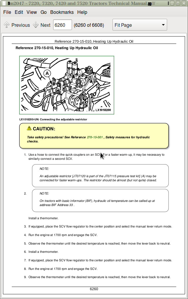
TCU 304156.01 - INFORMATION FOR THE OPERATOR: Transmission Warm-up Routine is Active
TCU 304157.01 - INFORMATION FOR THE OPERATOR: Transmission Warm-up Routine is Active
TCU 304160.09 - Engine Control Unit has Stopped Transmitting Data
TCU 304161.09 - User Interface Controller has Stopped Transmitting Data
TCU 304166.09 - Park Lock Controller has Stopped Transmitting Data
TCU 304176.00 - Dirty Transmission Oil Filter
TCU 304177.01 - Transmission Oil Pressure Too Low
TCU 304178.07 - Filter By-pass Valve (Cold-weather Starting) is Closed by Mistake
TCU 304179.07 - Filter By-pass Valve (Cold-weather Starting) is Opened by Mistake
TCU 304196.19 - Data Transmitted by Engine Control Unit is Incomplete (Engine Speed)
TCU 304200.19 - Data Transmitted by User Interface Controller is Incomplete (Desired Acceleration)
TCU 304202.19 - Data Transmitted by User Interface Controller is Incomplete (Clutch Torque)
TCU 304204.19 - Data Transmitted by User Interface Controller is Incomplete (Desired Transmission Ratio)
TCU 304206.19 - Data Transmitted by User Interface Controller is Incomplete (Park Lock Condition)
TCU 304208.19 - Data Transmitted by User Interface Controller is Incomplete (Direction of Travel)
TCU 304212.19 - Data Transmitted by User Interface Controller is Incomplete (Clutch Pedal Sensor)
TCU 304216.19 - Data Transmitted by User Interface Controller is Incomplete (Park Lock Activation)
TCU 304228.19 - Data Transmitted by Park Lock Controller is Incomplete (Transmission Output Speed)
TCU 304230.19 - Data Transmitted by Park Lock Controller is Incomplete (Park Lock Pressure Sender)
TCU 304232.19 - Data Transmitted by Park Lock Controller is Incomplete (Transmission Output Speed)
TCU 304234.19 - Data Transmitted by Park Lock Controller is Incomplete (State of Transmission Output Speed Sender)
TCU 304236.19 - Data Transmitted by Park Lock Controller is Incomplete (Park Lock Solenoid Valve Y15-2)
TCU 304240.19 - Data Transmitted by User Interface Controller is Incomplete (Status of "Come-Home" Mode)
TCU 304241.19 - Data Transmitted by User Interface Controller is Incomplete (Desired Acceleration during a Change of Direction)
TCU 304243.19 - Data Transmitted by User Interface Controller is Incomplete (Transmission Shift Monitor)
TCU 304244.19 - Data Transmitted by User Interface Controller is Incomplete (Change of Direction of Travel)
Group TEC: TEC Diagnostic Trouble Codes
Specifications
TEC 000158.00 - TEC Power Supply (Unswitched Power) Too High
TEC 000158.01 - TEC Power Supply (Unswitched Power) Too Low
TEC 000628.12 - TEC Controller is Connected to the Wrong Harness Connector
TEC 000629.12 - TEC Controller, Internal Fault (Watchdog Timeout)
TEC 000630.02 - TEC Controller, Internal Fault (EEPROM)
TEC 000639.12 - Tractor CAN BUS Fault
TEC 000639.14 - 29-bit Implement CAN BUS, Very High Error Rate
TEC 001231.12 - Fault in the 29-bit Tractor CAN BUS
TEC 001231.14 - 29-bit Tractor CAN BUS, Very High Error Rate
TEC 298751.31 - Fault in the Power Supply to Components at the Implement BUS or Fault in System Voltage (ELX)
TEC 298752.31 - Fault in the Power Supply to the Components at the Implement BUS
TEC 298753.31 - Fault in the Power Supply to the Components at the Implement BUS
TEC 298754.31 - Fault in the Power Supply to Components at the Implement BUS or Fault in System Voltage (ELX)
TEC 298786.04 - TEC Controller System Voltage (Unswitched Power) is Missing
TEC 298803.04 - TEC Controller System Voltage (ELX) is Missing
TEC 298804.31 - TEC Controller, Internal Fault (Shut-Off Process)
TEC 298805.31 - TEC Controller, Internal Fault (EEPROM)
TEC 299067.03 - Fault in Main Switch (ELX Voltage)
TEC 522550.14 - Implement Connected to 29-bit Implement CAN BUS is Not Compatible with ISO
TEC 523652.02 - TEC Controller is Connected to the Wrong Harness Connector
TEC 524287.31 - TEC 524287.31
Group UIC: UIC Diagnostic Trouble Codes
Specifications
UIC 305005.02 - Controller, Internal Fault
UIC 305006.02 - Controller, Internal Fault
UIC 305007.12 - Set-Up Error in BCU
UIC 305008.31 - INFORMATION FOR OPERATOR: Anti-jack-knife Control Activated
UIC 305009.04 - Defective Solenoid Valve in Anti-jack-knife Control
UIC 305010.07 - Fault at Brake Pedal Sensor
UIC 305011.11 - MFWD Speed and Transmission Output Speed Do Not Match
UIC 305012.00 - INFORMATION FOR OPERATOR: Engine Speed Too High
UIC 305015.11 - Park Lock Does Not Engage
UIC 305016.11 - UIC Detects Travel Speed even although the Park Lock is Engaged
UIC 305021.04 - Cruise Control Potentiometer, Signal Voltage Too Low
UIC 305022.03 - Cruise Control Potentiometer, Signal Voltage Too High
UIC 305027.04 - AutoPowr Selector, Signal Voltage Too Low
UIC 305028.03 - AutoPowr Selector, Signal Voltage Too High
UIC 305029.02 - Operator Presence (Seat) Switch, Faulty Signal
UIC 305030.12 - Accelerator Pedal Potentiometer, Voltages at Channel 1 and Channel 2 Not in the Correct Ratio
UIC 305032.04 - Accelerator Pedal Potentiometer, Voltage at Channel 1 Too Low
UIC 305033.03 - Accelerator Pedal Potentiometer, Voltage at Channel 1 Too High
UIC 305035.12 - Hand Throttle Potentiometer, Voltages at Channel 1 and Channel 2 Not in the Correct Ratio
UIC 305037.04 - Hand Throttle Potentiometer, Voltage at Channel 1 Too Low
UIC 305038.03 - Hand Throttle Potentiometer, Voltage at Channel 1 Too High
UIC 305039.11 - Fault at Clutch Pedal Sensor
UIC 305044.04 - Left Brake Signal Potentiometer, Voltage Too Low
UIC 305045.03 - Left Brake Signal Potentiometer, Voltage Too High
UIC 305046.04 - Right Brake Signal Potentiometer, Voltage Too Low
UIC 305047.03 - Right Brake Pedal Potentiometer, Voltage Too High
UIC 305050.12 - Speed Wheel, Output Signals do Not Match
UIC 305051.09 - Engine Control Unit has Stopped Transmitting Data (Engine Temperature)
UIC 305052.09 - Engine Control Unit has Stopped Transmitting Data (Engine Load/Maximum Injection Rate)
UIC 305053.09 - Engine Control Unit has Stopped Transmitting Data (Engine Speed)
UIC 305054.09 - Transmission Control Unit has Stopped Transmitting Data (Transmission Oil Temperature)
UIC 305055.09 - Engine Control Unit has Stopped Transmitting Data (Engine Load/Current Injection Rate)
UIC 305056.09 - Engine Control Unit has Stopped Transmitting Data (Engine Speed)
UIC 305057.01 - INFORMATION FOR OPERATOR: Transmission Warm-up Routine is Active
UIC 305058.01 - INFORMATION FOR OPERATOR: Transmission Warm-up Routine Cannot be Activated, Park Lock should be Engaged
UIC 305059.09 - Basic Control Unit has Stopped Transmitting Data (Status of Front-Wheel Drive)
UIC 305060.09 - Engine Control Unit has Stopped Transmitting Data (Torque Characteristics)
UIC 305062.31 - Tractor in "Come-Home" Mode - INFORMATION FOR OPERATOR: Release the Clutch Pedal
UIC 305063.31 - Tractor in "Come-Home" Mode - INFORMATION FOR OPERATOR: Move Reverse Drive Lever to Neutral or Park Position
UIC 305064.31 - Tractor in "Come-Home" Mode - INFORMATION FOR OPERATOR: Depress the Clutch Pedal Fully
UIC 305065.31 - Tractor in "Come-Home" Mode - INFORMATION FOR OPERATOR: Select a Direction of Travel
UIC 305066.31 - Tractor in "Come-Home" Mode - INFORMATION FOR OPERATOR: Press the Clutch Pedal to Stop
UIC 305067.31 - Tractor in "Come-Home" Mode - INFORMATION FOR OPERATOR: Restart
UIC 305070.19 - Transmission Control Unit is Transmitting Incomplete Data (Transmission Output Speed)
UIC 305075.04 - Left Brake Pedal Potentiometer Adjustment Error
UIC 305076.04 - Right Brake Pedal Potentiometer, Adjustment Error
UIC 305129.12 - Potentiometer of Speed Control Lever, Voltages at Channel 1 and Channel 2 not in the Correct Ratio
UIC 305131.04 - Speed Control Lever's Potentiometer, Voltage at Channel 1 Too Low
UIC 305132.03 - Speed Control Lever's Potentiometer, Voltage at Channel 1 Too High
UIC 305135.02 - Neutral Switch and a Park Lock Switch are Actuated Simultaneously for Too Long a Period
UIC 305136.02 - Reverse Drive Lever, Faulty Signals
UIC 305137.02 - Power-Zero Switch, Move Switch and either the Forward or Reverse Switch are Activated Simultaneously for too Long a Period
UIC 305138.11 - Park Lock cannot be Disengaged
UIC 305139.02 - INFORMATION FOR OPERATOR: Direction of Travel is Preselected without there being a Valid Signal indicating Operator Presence
UIC 305140.02 - INFORMATION FOR OPERATOR: Power Zero is Preselected without there being a Valid Signal indicating Operator Presence
UIC 305141.12 - Clutch Pedal Potentiometer, Voltages at Channel 1 and Channel 2 not in the Correct Ratio
UIC 305142.04 - Clutch Pedal Potentiometer, Voltage at Channel 1 Too Low
UIC 305143.03 - Clutch Pedal Potentiometer, Voltage at Channel 1 Too High
UIC 305144.02 - Switches on Reverse Drive Lever are Actuated Simultaneously
UIC 305145.02 - No Switch Signal from Reverse Drive Lever
UIC 305146.02 - Move Switch or Power Zero Switch has been Opened by Mistake
UIC 305147.02 - Forward And Reverse Switches Actuated At Same Time
UIC 305148.02 - Forward Switch or Reverse Switch has been Opened by Mistake
UIC 305149.02 - Fault at Neutral Switch or Power Zero Switch
UIC 305150.02 - Fault at Park Lock Switch
UIC 305151.02 - Fault at Neutral Switch
UIC 305152.02 - Fault at Move Switch
UIC 305153.02 - Fault at Reverse Switch
UIC 305154.02 - Fault at Forward Switch
UIC 305155.02 - Forward or Reverse Switch is Actuated Simultaneously with the Park Lock Switch
UIC 305157.02 - Fault in Speed Range 2
UIC 305158.02 - Fault in Speed Range 1
UIC 305160.02 - Faulty Power Supply to Reverse Drive Lever
UIC 305170.19 - Transmission Control Unit and Park Lock Controller are Transmitting Incomplete Data (Transmission Output Speed)
UIC 305179.02 - 5-Volt Power Supply is Faulty
UIC 305180.04 - 5-Volt Power Supply Too Low
UIC 305184.01 - INFORMATION FOR OPERATOR: Engine Has Stopped - Reverse Drive Lever Still in Position for a Direction of Travel
UIC 305185.01 - Fault at Transmission
UIC 305189.02 - Fault in Circuit of Transmission Enable Relay
UIC 305190.09 - Transmission Control Unit has Stopped Transmitting Data
UIC 305207.02 - INFORMATION FOR OPERATOR: Tractor Start-up with Reverse Drive Lever Not in Neutral or Park
UIC 305208.02 - Internal Transmission Power Supply (VPS), Shorted Circuit
UIC 305209.02 - INFORMATION FOR OPERATOR: Reverse Drive Lever is in the Position for Forward or Reverse Travel During Start-up Procedure
UIC 305230.02 - Controller, Internal Fault
UIC 305240.11 - Controller Connected to Wrong Wiring Harness Connector
UIC 305250.12 - Controller, Wrong Input Value
Section 212: OBSERVABLE SYMPTOMS
Group 20: Engine
No Hand Throttle Response
Group 40: Electrical System
Specifications
Control Unit(s) Not Displayed (Tractors with Cab)
Control Unit(s) Not Displayed (Open Operator's Station)
Diagnostic Mode Cannot Be Entered or Connection Problems with Service ADVISOR (Tractors with Cab)
No Access to Diagnostic Mode Possible or Connection Difficulties with Service ADVISOR (Tractors with Open Operator's Station: TIER I Engines)
No Access to Diagnostic Mode Possible (Vehicles with Open Operator's Station; TIER II Engines & Level 12)
Problems After Installing New Control Unit or Software
Reprogramming was aborted.
Problem with the Battery
Problem with the Starting Motor
Problem with the Horn
Problem with the Windshield Wiper
Problem with the Windshield Washer
Problem with the Rear Window Wiper
Problem with the Rear Window Washer
BCU Hitch Codes on No Hitch Tractor
Group 50: Transmission
Specifications
Problem with PowrQuad Transmission
Problem with PowrQuad-Plus Transmission
AutoPowr/IVT Transmission - Noise/Vibration Problem
AutoPowr/IVT Transmission Problem
Problem with AutoPowr / IVT Transmission
Group 56: Drive Systems
Specifications
Problem with the Rear PTO
Problem with the Front PTO
Group 60: Steering and Brakes
Specifications
Problem with the Brakes
Problem with the Steering
Group 70: Hydraulic System
Loss of Hydraulics at Start-Up
Stepper Motor Performance Issue
SCV Coupler Leaking Oil
Hitch Hunting or Surging
Problem with the Rockshaft
Problem with the Rockshaft's Remote Control
Group 90: Operator's Cab
Problem with Operator's Seat
Problem with the Air-Conditioning System
Section 213: SYSTEM DIAGNOSTICS
Group 45: Electronics
Specifications
29-bit CAN BUS - Check (Tractors with Cab)
11-bit CAN BUS - Check
29-bit CAN BUS - Check (Tractors with Open Operator's Station and TIER I Engines)
29-bit CAN BUS - Check (Tractors with Open Operator's Station and TIER II Engines; Level 12)
JDLink System Check
Section 220: ENGINE
Group 05: Additional Information
Reference 220-05-001, Engine Wiring—Summary of References
Group 10: Operational Checkout
Reference 220-10-010, Safety
Reference 220-10-020, Preliminary Engine Tests
Group 15: Checks and Adjustments
Reference 220-15-010, Dynamometer Test
Group 20: Theory of Operation
Reference 220-20-010, Distinguishing Engine Control Units (ECUs)
Section 230: FUEL, AIR INTAKE AND COOLING SYSTEMS
Group 15: Tests and Adjustments
Specifications
Reference 230-15-001, Tests and Adjustments—Summary of References
Reference 230-15-010, General Information
Reference 230-15-020, Explanation of Checks
Reference 230-15-030, Safety
Reference 230-15-040, Special Tools
Reference 230-15-050, Specifications
Reference 230-15-060, Air Intake System Test
Reference 230-15-070, Checking the Cooling System for Leaks
Reference 230-15-075, Flow-testing in the Low-Temperature Circuit (not for tractors with AutoPowr)
Reference 230-15-076, Flow-testing in the Low-Temperature Circuit (tractors with AutoPowr)
Reference 230-15-080, Testing the Temperature at which the Thermostat opens
Reference 230-15-090, Viscous Fan Drive Test
Reference 230-15-100, Checking the Fuel Transfer Pump
Reference 230-15-110, Hand Throttle Lever and Accelerator Pedal Adjustment
Reference 230-15-120, Accelerator Pedal Adjustment
Group 20: Descriptions
Specifications
Reference 230-20-001, Component Description - Summary of References
Reference 230-20-010, Fuel System - Description
Reference 230-20-020, Air Intake System - Theory of Operation
Reference 230-20-030, Coolant Circuit - Description
Reference 230-20-040, Cooling System Radiator - Description
Reference 230-20-050, Intercooler - Description
Reference 230-20-060, Ring-Shaped (Transmission Oil) Cooler - Description
Reference 230-20-070, Viscous Fan Drive - Theory of Operation
Reference 230-20-072, Coolant Pumps in Low-Temperature Circuit (AutoPowr/IVT) - Operation
Reference 230-20-080, Automatic Drive Belt Tensioner - Theory of Operation
Reference 230-20-090, Cold Weather Starting Aids - Theory of Operation
Section 240: ELECTRICAL SYSTEM
Group 10: Sub-System Diagnostics
Reference 240-10-001, Sub-System Diagnostics (Cab) — Summary of References
Reference 240-10-002, Special Tools
Reference 240-10-003, SE1 — Starter Motor and Charging Circuit, Tier 2 Engines
Reference 240-10-050, SE1 — Starting Motor and Charging Circuit, Tier 3 Engines
Reference 240-10-004, SE2 — Basic Informator
Reference 240-10-005, SE3 — Horn
Reference 240-10-006, SE4 — Cigarette Lighter and Operator's Seat
Reference 240-10-007, SE6 — Lights
Reference 240-10-008, SE7— Worklights
Reference 240-10-009, SE8 — Front Loader Plug
Reference 240-10-010, SE9 — Radio, Digital Clock, Dome, Console and Access Step Lights
Reference 240-10-011, SE10 — Fan, Air Conditioner and Automatic Air Conditioning Control (ClimaTrak)
Reference 240-10-012, SE11—Windshield Wiper and Washer
Reference 240-10-013, SE12 — Rear Window Wiper and Washer
Reference 240-10-014, SE13 — Beacon Light
Reference 240-10-015, SE14 — Power Outlet Sockets, 3- and 7-Terminal
Reference 240-10-016, SE15 — Electronic Hitch Control
Reference 240-10-017, SE16A — Basic Control Unit (BCU) (Rear PTO and External Control)
Reference 240-10-018, SE16B — Basic Control Unit (BCU) (Front PTO)
Reference 240-10-019, SE16C — Basic Control Unit (BCU) (MFWD)
Reference 240-10-020, SE16D — Basic Control Unit (BCU) (Differential Lock)
Reference 240-10-021, SE16E — Basic Control Unit (BCU) (Hazard Warning and Turn Signal Lights)
Reference 240-10-022, SE16F — Basic Control Unit (BCU) (Speed Sensor and Radar) (AutoPowr / IVT Transmission)
Reference 240-10-023, SE16G — Basic Control Unit (BCU) (Headland Management System II)
Reference 240-10-024, SE16H — Basic Control Unit (BCU) (Power Supply, Acoustic Alarm, CAN Bus Connection)
Reference 240-10-025, SE16I — Basic Control Unit (BCU) (Intercooler)
Reference 240-10-026, SE16J — Basic Control Unit (BCU) (Braking System and Handbrake Monitor Unit)
Reference 240-10-027, SE17 — Signal and Service Sockets
Reference 240-10-028, SE18 — Performance Monitor
Reference 240-10-029, SE20 — MFWD Axle with TLS and CSC Cab Suspension
Reference 240-10-030, SE21 — Electronic Actuation of SCVs
Reference 240-10-031, SE21A — Stepper Motor Driver for Electronic Independent Control Valves (E-ICV)
Reference 240-10-032, SE21B — Stepper Motor Driver for Electronic Selective Control Valves (E-SCV)
Reference 240-10-033, SE22 — BUS Terminator and Terminating Resistor
Reference 240-10-052, SE23A - Electronic Engine Control, Level 1 ECU (Stage I engines to 97/68/EC) and Level 12 ECU (Stage II engines to 97/68/EC)
Reference 240-10-034, SE23B — Electronic Engine Control (ECU Level 4 and Level 11)
Reference 240-10-046, SE25 — Back-Up Alarm
Reference 240-10-035, SE26 — Transmission Control (AutoPowr/IVT Transmission)
Reference 240-10-053, SE26A - Transmission Control (EPC) and Electrical Forward/Reverse Controls (PowrQuad, PowrQuad-Plus Transmissions)
Reference 240-10-036, SE27 — Transmission Shift (AutoPowr / IVT Transmission)
Reference 240-10-037, SE28 — Electronic Park Lock (AutoPowr / IVT Transmission)
Reference 240-10-040, SE29 — Electrical Rear-View Mirror
Reference 240-10-038, SE30 — JDLink Control Unit
Reference 240-10-039, SE31 — Heated Rear Window
Reference 240-10-041, SE32 — Control Unit TEC and 60-amp Socket (Implement-BUS)
Reference 240-10-042, SE33 — GreenStar
Reference 240-10-045, SE35 — Automatic Steering System (AutoTrac)
Reference 240-10-047, SE37 — Electro-Hydraulic Pick-Up Hitch
Group 10A: Sub-System Diagnostics (Open Operator's Station)
Reference 240-10A-001, Sub-System Diagnostics (Open Operator's Station) - Summary of References
Reference 240-10A-002, Special Tools
Reference 240-10A-003, SE1—Starter Motor and Charging Circuit
Reference 240-10A-004, SE2 - Basic Informator
Reference 240-10A-005, SE3—Horn
Reference 240-10A-006, SE4—Operator's Seat
Reference 240-10A-007, SE6—Lights
Reference 240-10A-008, SE7—Work lights
Reference 240-10A-009, SE14—3- and 7-Terminal Power Outlet Sockets
Reference 240-10A-010, SE15—Electronic Hitch Control
Reference 240-10A-011, SE16A - Basic Control Unit (BCU) (Rear PTO)
Reference 240-10A-012, SE16B—Basic Control Unit (BCU) (Front PTO)
Reference 240-10A-013, SE16C—Basic Control Unit (BCU) (MFWD)
Reference 240-10A-014, SE16D—Basic Control Unit (BCU) (Differential Lock)
Reference 240-10A-015, SE16E— Basic Control Unit (BCU) (Hazard Flasher and Turn Signal Unit)
Reference 240-10A-016, SE16F—Basic Control Unit (BCU) (Speed Sending Units)
Reference 240-10A-017, SE16H—Basic Control Unit (BCU) (Power Supply, Acoustic Alarm)
Reference 240-10A-018, SE16J—Basic Control Unit (BCU) (Braking System and Bus Connection)
Reference 240-10A-019, SE17—Signal Socket
Reference 240-10A-020, SE22 — BUS Terminator and Terminating Resistor
Reference 240-10A-021, SE23 — Electronic Engine Control
Reference 240-10A-051, SE16F — Basic Control Unit (BCU) (Speed Sensor and Radar) (PowrQuad-Plus Transmission)
Reference 240-10A-052, SE23A — Electronic Engine Control (ECU Level 1 and ECU Level 12)
Reference 240-10A-053, SE26A — Transmission Control (PowrQuad Plus Transmissions)
Reference 240-10A-054, SE26C — Electrical Reverser (PowrQuad Plus Transmissions)
Group 15: Component Testing
Specifications
Reference 240-15-001, SE01 — Starter Motor and Charging Circuit
Reference 240-15-002, SE02 — Basic Informator
Reference 240-15-003, SE03 — Horn
Reference 240-15-004, SE04 — Cigarette Lighter and Operator's Seat
Reference 240-15-005, SE06 — Lighting Circuits
Reference 240-15-006, SE07—Work lights
Reference 240-15-007, SE09 — Radio, Dome Light and Console Light
Reference 240-15-008, SE10 — Blower and Air Conditioner
Reference 240-15-009, SE11 and SE12 — Wiper and Washer System
Reference 240-15-010, SE13 — Beacon Light
Reference 240-15-011, SE14 — Sockets, 3- and 7-Terminal
Reference 240-15-012, SE15 — Electronic Hitch Control
Reference 240-15-013, SE16A — Basic Control Unit (BCU) (Rear PTO and External Control)
Reference 240-15-014, SE16B — BCU (Front PTO)
Reference 240-15-015, SE16C — BCU (MFWD)
Reference 240-15-016, SE16D — BCU (Differential Lock)
Reference 240-15-017, SE16E - Basic Control Unit (BCU) (Hazard Flasher and Turn Signal Unit)
Reference 240-15-018, SE16G — Basic Control Unit (BCU) (HMS)
Reference 240-15-019, SE16H — Basic Control Unit (BCU) (Power Supply, Acoustic Alarm)
Reference 240-15-020, SE16I - Basic Control Unit (BCU) (Intercooler)
Reference 240-15-021, SE16J — Basic Control Unit (BCU) (Braking System and Handbrake Monitor Unit)
Reference 240-15-022, SE20 — MFWD Axle with TLS and Cab Suspension
Reference 240-15-023, SE21 — Electronic Actuation of SCVs
Reference 240-15-024, SE22 — CAN BUS Terminating Resistor
Reference 240-15-025, SE23 — Electronic Engine Control
Reference 240-15-026, SE26A — Transmission Control (PowrQuad-Plus Transmission)
Reference 240-15-027, SE26C — Electrical Reverser Control (PowrQuad-Plus Transmissions)
Reference 240-15-028, SE27 — Transmission Shift (AutoPowr / IVT Transmissions)
Reference 240-15-029, SE28 — Electronic Park Lock (AutoPowr / IVT Transmissions)
Reference 240-15-030, SE29 — Electrically-Adjustable Outside Mirrors
Reference 240-15-031, SE31 — Heated Rear Window
Reference 240-15-032, SE32 — 60-amp GreenStar socket (with and without TECU)
Group 25: Functional Schematics (AutoPowr / IVT Transmission)
Reference 240-25-001, Functional Schematic and Fuses (AutoPowr / IVT Transmission) — Summary of References
Reference 240-25-002, Fuses
Reference 240-25-003, Designation of Parts Shown in Functional Schematic and Harness Diagram
Reference 240-25-004, Designation of Sections Shown in Functional Schematic
Reference 240-25-005, Wiring Harness Designations
Reference 240-25-006, Functional Schematic (Complete Tractor)
Reference 240-25-007, Fuses from Serial No. 12451
Group 25A: Functional Schematics (PowrQuad-Plus Transmission)
Reference 240-25A-001, Functional Schematic and Wiring Harnesses (PowrQuad-Plus Transmission) — Summary of References
Reference 240-25A-010, Fuses
Reference 240-25A-011, Designation of Parts Shown in Functional Schematic and Harness Diagram
Reference 240-25A-012, Designation of Sections Shown in Functional Schematic
Reference 240-25A-013, Wiring Harness Designations
Reference 240-25A-014, Functional Schematic (Complete Tractor)
Reference 240-25A-015, Fuses from Serial No. 12451
Group 25B: Functional Schematics (Open Operator's Station)
Reference 240-25B-001, Functional Schematic and Wiring Harnesses (Open Operator's Station) — Summary of References
Reference 240-25B-002, Fuses and Relays
Reference 240-25B-003, Designation of Parts Shown in Functional Schematic and Harness Diagram
Reference 240-25B-004, Designation of Sections Shown in Functional Schematic
Reference 240-25B-005, Wiring Harness Designations
Reference 240-25B-006, Functional Schematic (Complete Tractor)
Group 26: Wiring Harnesses
Reference 240-26-002, Wiring Harnesses for 7320, 7420 and 7520 Tractors with PowrQuad-Plus Transmission and TIER I Engine — Summary of References
Reference 240-26-003, Wiring Harnesses for Tractors with AutoPowr / IVT Transmission and TIER I Engine — Summary of References
Reference 240-26-004, Wiring Harnesses for 7220 Tractors with PowrQuad-Plus Transmission and TIER I Engine — Summary of References
Reference 240-26-006, Wiring Harnesses for Tractors with Open Operator's Station and TIER I Engine — Summary of References
Reference 240-26-011, W01 — Wiring Harness - Power Supply
Reference 240-26-013, W01 — Wiring Harness - Power Supply (Open Operator's Station)
Reference 240-26-021, W02 — Engine Wiring Harness for TIER I Engine (without Engine Control or with Level 1 ECU)
Reference 240-26-023, W02 — Engine Wiring Harness for TIER I Engines (Level 4 ECU)
Reference 240-26-025, W02 — Engine Wiring Harness for TIER I Engines (Open Operator's Station)
Reference 240-26-031, W03 — Wiring Harness - Starting Aid for TIER I and II Engines (without Engine Control or with Level 1 or Level 12 ECUs)
Reference 240-26-032, W03 — Wiring Harness - Starting Aid for TIER I and II Engines (Level 4 or 11 ECUs)
Reference 240-26-033, W03 — Wiring Harness - Starting Aid for TIER I and II Engines (Level 4 or 11 ECUs) (AutoPowr / IVT Transmission)
Reference 240-26-042, W04 — Wiring Harness - Head lights
Reference 240-26-061, W06 — Wiring Harness - MFWD Axle with TLS
Reference 240-26-071, W07 — Wiring Harness - Front PTO
Reference 240-26-081, W08 — Wiring Harness Summary of References - Cab, with TIER I Engine (PowrQuad Transmission)
Reference 240-26-081A, W08 — Wiring Harness (Fuses) - Cab, with TIER I Engine (PowrQuad Transmission)
Reference 240-26-081B, W08 — Wiring Harness (Relays and Diodes) - Cab, with TIER I Engine (PowrQuad Transmission)
Reference 240-26-081C, W08 — Wiring Harness (Connectors) - Cab, with TIER I Engine (PowrQuad Transmission)
Reference 240-26-081D, W08 — Wiring Harness (Ground Points) - Cab, with TIER I Engine (PowrQuad Transmission)
Reference 240-26-082, W08 — Wiring Harness Summary of References - Cab, with TIER I Engine (AutoPowr / IVT Transmission)
Reference 240-26-082A, W08 — Wiring Harness (Fuses) - Cab, with TIER I Engine (AutoPowr / IVT Transmission)
Reference 240-26-082B, W08 — Wiring Harness (Relays and Diodes) - Cab, with TIER I Engine (AutoPowr / IVT Transmission)
Reference 240-26-082C, W08 — Wiring Harness (Resistors) - Cab, with TIER I Engine (AutoPowr / IVT Transmission)
Reference 240-26-082D, W08 — Wiring Harness (Connectors) - Cab, with TIER I Engine (AutoPowr / IVT Transmission)
Reference 240-26-082E, W08 — Wiring Harness (Ground Points) - Cab, with TIER I Engine (AutoPowr / IVT Transmission)
Reference 240-26-083, W08 — Wiring Harness Summary of References - Open Operator's Station, with TIER I Engine
Reference 240-26-083A, W08 — Wiring Harness (Fuses) - Open Operator's Station, with TIER I Engine
Reference 240-26-083B, W08 — Wiring Harness (Relays and Diodes) - Open Operator's Station, with TIER I Engine
Reference 240-26-083C, W08 — Wiring Harness (Resistors) - Open Operator's Station, with TIER I Engine
Reference 240-26-083D, W08 — Wiring Harness (Connectors) - Open Operator's Station, with TIER I Engine
Reference 240-26-083E, W08 — Wiring Harness (Ground Points) - Open Operator's Station, with TIER I Engine
Reference 240-26-091, W09 — Wiring Harness - Cowl, with TIER I Engine
Reference 240-26-092, W09 — Wiring Harness - Cowl, with TIER I Engine (AutoPowr / IVT Transmission)
Reference 240-26-094, W09 — Wiring Harness - Cowl, with TIER I Engine (Open Operator's Station)
Reference 240-26-101, W10 — Wiring Harness - Shift Console
Reference 240-26-111, W11 — Wiring Harness - Transmission Shift and Hand Throttle
Reference 240-26-112, W11 — Wiring Harness - Speed Control Lever and Hand Throttle (AutoPowr / IVT Transmission)
Reference 240-26-122, W12 — Wiring Harness - Command Arm (AutoPowr / IVT Transmission)
Reference 240-26-131, W13 — Wiring Harness - Clutch Sender
Reference 240-26-141, W14 — Wiring Harness - 3-Terminal Power Outlet Socket (Open Operator's Station)
Reference 240-26-144, W14 — Wiring Harness - 3-Terminal Power Outlet Socket
Reference 240-26-152, W15 — ECU Wiring Harness for TIER I Engines (Level 4 ECU)
Reference 240-26-153, W15 — ECU Wiring Harness for TIER I Engines (without Engine Control)
Reference 240-26-161, W16 — SIC Wiring Harness for TIER I Engines
Reference 240-26-171, W17 — Wiring Harness - Multifunction Unit
Reference 240-26-181, W18 — Wiring Harness - Windshield Wiper Switch (without Intermittent Wipe)
Reference 240-26-182, W18 — Wiring Harness - Windshield Wiper Switch (with Intermittent Wipe)
Reference 240-26-191, W19 — Wiring Harness - Cab Roof, with TIER I Engines
Reference 240-26-201, W20 — Wiring Harness - Turn Signal and Clearance Lights
Reference 240-26-211, W21 — Wiring Harness - Worklights on Front of Cab Roof
Reference 240-26-221, W22 — Wiring Harness - Worklights on Rear of Cab Roof
Reference 240-26-222, W22 — Wiring Harness - Xenon Work lights on Rear of Cab Roof
Reference 240-26-231, W23 — Wiring Harness - Windshield Wiper (Without Switch for Windshield)
Reference 240-26-232, W23 — Wiring Harness - Windshield Wiper (With Switch for Windshield)
Reference 240-26-241, W24 — Wiring Harness - Rear Window Wiper
Reference 240-26-251, W25 — Wiring Harness - Rear Window Wiper Switch
Reference 240-26-261, W26 — Wiring Harness - Blower and Air Conditioner
Reference 240-26-281, W28 — Wiring Harness - Front End of Transmission
Reference 240-26-284, W28 — Wiring Harness - Front End of Transmission (Open Operator's Station)
Reference 240-26-285, W28 — Wiring Harness - Front Part of Transmission (AutoPowr / IVT Transmission)
Reference 240-26-286, W28 — Wiring Harness - Front End of Transmission (AutoPowr / IVT Transmission - 7420 and 7520 Tractors)
Reference 240-26-291, W29 — Wiring Harness - Valve Block (AutoPowr / IVT Transmission)
Reference 240-26-292, W29 — Wiring Harness - Valve Block with GreenStar Connection (AutoPowr / IVT Transmission)
Reference 240-26-301, W30 — Wiring Harness - Rear of Transmission (7220 and 7320 Tractors)
Reference 240-26-302, W30 — Wiring Harness - Rear of Transmission (7420 and 7520 Tractors)
Reference 240-26-303, W30 — Wiring Harness - Rear Part of Transmission (7220 and 7320 Tractors)
Reference 240-26-304, W30 — Wiring Harness - Rear Part of Transmission (7420 and 7520 Tractors)
Reference 240-26-306, W30 — Wiring Harness - Rear of Transmission (Open Operator's Station)
Reference 240-26-311, W31 — Wiring Harness - 7-Terminal Power Outlet Socket
Reference 240-26-321, W32 — Wiring Harness - Stepper Motors, with TIER I Engines
Reference 240-26-821, W32 — Wiring Harness - Stepper Motors, with TIER II Engines
Reference 240-26-331, W33 — Wiring Harness - Service
Reference 240-26-341, W34 — Wiring Harness - Electric Rear-View Mirrors
Reference 240-26-351, W35 — Wiring Harness - Access-Step Light and Battery Cut-Off Switch
Reference 240-26-361, W36 — Wiring Harness - 60 A GreenStar Socket
Reference 240-26-371, W37 — Wiring Harness - GreenStar Port
Reference 240-26-391, W39 — Wiring Harness - GreenStar (Cab)
Reference 240-26-392, W39 — Wiring Harness - GreenStar (Cab) with TEC
Reference 240-26-401, W40 — Wiring Harness - GreenStar (Cab Roof)
Reference 240-26-411, W41 — Wiring Harness - JDLink
Reference 240-26-421, W42 — Wiring Harness - Battery Cut-Off Switch
Reference 240-26-431, W43 — Wiring Harness - Back-up Alarm
Reference 240-26-432, W43 — Wiring Harness - Back-up Alarm (AutoPowr/IVT Transmission)
Reference 240-26-441, W44 — Wiring Harness - Back-up Alarm / Switch for PowrQuad Transmission
Reference 240-26-501— Wiring Harnesses for Tractors with PowrQuad-Plus Transmission and TIER II Engine — Summary of References
Reference 240-26-502— Wiring Harnesses for Tractors with AutoPowr / IVT Transmission and TIER II Engine — Summary of References
Reference 240-26-503— Wiring Harnesses for Tractors with Open Operator's Station and TIER II Engine — Summary of References
Reference 240-26-521, W02 — Engine Wiring Harness for TIER II Engines (Level 11 ECU)
Reference 240-26-524, W02 — Engine Wiring Harness for TIER II Engines (Level 12 ECU) (Open Operator's Station)
Reference 240-26-561, W16 — SIC Wiring Harness for TIER II Engines
Reference 240-26-581, W08 — Wiring Harness - Cab, with TIER II Engine
Reference 240-26-582, W08 — Wiring Harness - Cab, with TIER II Engine (AutoPowr / IVT Transmission)
Reference 240-26-583, W08 — Wiring Harness - Open Operator's Station, with TIER II Engine
Reference 240-26-591, W09 — Wiring Harness - Cowl, with TIER II Engine
Reference 240-26-592, W09 — Wiring Harness - Cowl, with TIER II Engine (AutoPowr / IVT Transmission)
Reference 240-26-593, W09 — Wiring Harness - Cowl, with TIER II Engine (Open Operator's Station)
Reference 240-26-651, W15 — ECU Wiring Harness for TIER II Engines (Level 11 ECU)
Reference 240-26-691, W19 — Wiring Harness - Cab Roof, with TIER II Engines
Group 26B: Wiring Harnesses from Serial No. 12451
Reference 240-26-702, Wiring Harnesses for Tractors with PowrQuad Plus Transmission from Serial No. 12451 — Summary of References
Reference 240-26-703, Wiring Harnesses for Tractors with AutoPowr/IVT Transmission from Serial No. 12451 — Summary of References
W02 — Engine Wiring Harness (ECU Level 11) from Serial No. 12451
W02 — G02
W02 — M01
W02 — X02
W02 — X66/1
W02 — X66/2
W02 — X70
W02 — X79
W02 — X130
W02 — X205
W02 — X261
W02 — X301
W02 — X305
W02 — X356
W02 — X358
W02 — X359
W02 — X411
W02 — X450
W02 — X451
W02 — X547
W02 — X550
W02 — X566
W02 — X567
W02 — X568
W02 — X575
W02 — X604
W02 — X610
W02 — X625
W02 — XGND9
W02/1 — Engine wiring harness (ECU Level 12) from serial no. 12451
W02/1 — G02
W02/1 — M01
W02/1 — X02
W02/1 — X66/1
W02/1 — X66/2
W02/1 — X70
W02/1 — X78
W02/1 — X79
W02/1 — X130
W02/1 — X205
W02/1 — X214
W02/1 — X301
W02/1 — X305
W02/1 — X353
W02/1 — X356
W02/1 — X411
W02/1 — X450
W02/1 — X547
W02/1 — X550
W02/1 — X567
W02/1 — X575
W02/1 — X604
W02/1 — XGND9
W03 — Starting Aid Wiring Harness (ECU Level 11) from Serial No. 12451
W03 — F09
W03 — F11
W03 — G02
W03 — K01
W03 — K36
W03 — X547
W03 — X630
W03/1 — Starting Aid Wiring Harness (ECU Level 11) with AutoPowr/IVT Transmission, from Serial No. 12451
W03/1 — F09
W03/1 — F11
W03/1 — F22
W03/1 — G02
W03/1 — K01
W03/1 — K36
W03/1 — X528
W03/1 — X547
W03/1 — X630
W03/2 — Starting Aid Wiring Harness (ECU Level 12) from Serial No. 12451
W03/2 — D31
W03/2 — F09
W03/2 — F11
W03/2 — G02
W03/2 — K01
W03/2 — K36
W03/2 — R15
W03/2 — X547
W08 — Wiring Harness - Cab from Serial No. 12451
W08 — F03
W08 — F04
W08 — F05
W08 — F06
W08 — F07
W08 — K01
W08 — K02
W08 — K08
W08 — K09
W08 — K10
W08 — X14/1
W08 — X14/2
W08 — X34
W08 — X35
W08 — X37
W08 — X37/3
W08 — X40
W08 — X44
W08 — X106
W08 — X107
W08 — X113/1
W08 — X113/2
W08 — X122
W08 — X125
W08 — X127
W08 — X128
W08 — X132
W08 — X171/1F
W08 — X171/1M
W08 — X171/2F
W08 — X171/2M
W08 — X174
W08 — X230
W08 — X235
W08 — X236
W08 — X239
W08 — X242
W08 — X243
W08 — X245
W08 — X247
W08 — X248
W08 — X260
W08 — X285
W08 — X371
W08 — X400
W08 — X403
W08 — X404
W08 — X409
W08 — X409/2
W08 — X423
W08 — X430
W08 — X440
W08 — X450
W08 — X460/1
W08 — X471
W08 — X472/1
W08 — X472/2
W08 — X473
W08 — X483/1
W08 — X483/2
W08 — X485
W08 — X488
W08 — X500
W08 — X503
W08 — X522
W08 — X544
W08 — X545
W08 — X571
W08 — X577
W08 — X577/1
W08 — X623
W08 — X651
W08 — X653
W08 — X657
W08 — X660
W08 — XGND1
W08 — XGND4
W08 — XGND5
W08 — XGND6
W08 — XGND43
W08 — XGND44
W08 — XGND45
W08 — XGND47
W08 — XGND48
W08 — XGND49
W08 — XGND50
W08 — XGND52
W08/1 — Cab Wiring Harness (with AutoPowr/IVT Transmission), from Serial No. 12451
W08/1 — F03
W08/1 — F04
W08/1 — F05
W08/1 — F06
W08/1 — F07
W08/1 — K01
W08/1 — K02
W08/1 — K08
W08/1 — K09
W08/1 — K10/1
W08/1 — R18
W08/1 — X34
W08/1 — X35
W08/1 — X37
W08/1 — X37/3
W08/1 — X40
W08/1 — X44
W08/1 — X106
W08/1 — X107
W08/1 — X113/1
W08/1 — X113/2
W08/1 — X122
W08/1 — X128
W08/1 — X132
W08/1 — X133
W08/1 — X171/1F
W08/1 — X171/1M
W08/1 — X171/2F
W08/1 — X171/2M
W08/1 — X174
W08/1 — X230
W08/1 — X235
W08/1 — X236
W08/1 — X239
W08/1 — X242
W08/1 — X243
W08/1 — X245
W08/1 — X247
W08/1 — X248
W08/1 — X260
W08/1 — X285
W08/1 — X332
W08/1 — X367
W08/1 — X371
W08/1 — X382
W08/1 — X400
W08/1 — X403
W08/1 — X404
W08/1 — X409
W08/1 — X422
W08/1 — X423
W08/1 — X430
W08/1 — X440
W08/1 — X450
W08/1 — X472/1
W08/1 — X472/2
W08/1 — X473
W08/1 — X481
W08/1 — X482
W08/1 — X483/1
W08/1 — X483/2
W08/1 — X484
W08/1 — X485
W08/1 — X488
W08/1 — X522
W08/1 — X544
W08/1 — X545
W08/1 — X571
W08/1 — X577
W08/1 — X577/1
W08/1 — X623
W08/1 — XGND1
W08/1 — XGND4
W08/1 — XGND5
W08/1 — XGND6
W08/1 — XGND43
W08/1 — XGND44
W08/1 — XGND45
W08/1 — XGND47
W08/1 — XGND48
W08/1 — XGND49
W08/1 — XGND50
W08/1 — XGND52
W09 — Wiring Harness - Cowl from Serial No. 12451
W09 — S01
W09 — S09
W09 — X20A
W09 — X20B
W09 — X25
W09 — X26
W09 — X120/1
W09 — X120/2
W09 — X126
W09 — X238
W09 — X322
W09 — X324
W09 — X403
W09 — X404
W09 — X487
W09 — X615
W09 — X654
W09 — XGND40
W09/1 — Cowl Wiring Harness (with AutoPowr/IVT Transmission), from Serial No. 12451
W09/1 — S01
W09/1 — S09
W09/1 — X20A
W09/1 — X20B
W09/1 — X25
W09/1 — X26
W09/1 — X120/1
W09/1 — X120/2
W09/1 — X126
W09/1 — X322
W09/1 — X323
W09/1 — X324
W09/1 — X343
W09/1 — X403
W09/1 — X404
W09/1 — X487
W09/1 — X615
W09/1 — XGND40
W15 — Wiring Harness - Engine Control Unit ECU (ECU Level 11) from Serial No. 12451
W15 — X409
W15 — X451
W15 — X570/1
W15 — X570/2
W15 — X610
W15/1 — Wiring Harness - Engine Control Unit ECU (ECU Level 12) from Serial No. 12451
W15/1 — X409
W15/1 — X409/2
W15/1 — X570
W26 — Wiring Harness - Blower and Air Conditioner from Serial No. 12451
W26 — X28
W26 — X46
W26 — X47
W26 — X48
W26 — X73/1
W26 — X73/2
W26 — X100
W26 — X448
W26 — X449/1
W26 — X449/2
W26 — X577
W26 — X665
W26 — XGND15
W26/1 — Wiring Harness-ClimaTrak (Cab)
W26/1 — X577
W26/1 — X577/1
W26/1 — X595
W26/1 — X599
W26/1 — X600
W26/1 — X602
W26/1 — X655
W26/1 — X664
W26/1 — XGND15
W36 - Wiring Harness-60-amp GreenStar Implement Socket
W36 — F16
W36 — F17
W36 — K46
W36 — K47
W36 — R20
W36 — R21
W36 — X533/1
W36 — X533/2
W36 — X533/3
W36 — X541
W36 — X543
W36 — X574
W36 — XGND51
W39 — GreenStar Wiring Harness (Cab)
W39 — K51
W39 — X522
W39 — X535
W39 — X543
W39 — X571F
W39 — X571M
W39 — X591F
W39 — X591M
W39/1 — Wiring Harness - GreenStar with TEC (Cab)
W39/1 — X522
W39/1 — X535
W39/1 — X543
W39/1 — X571F
W39/1 — X571M
W39/1 — X572
W39/1 — X591F
W39/1 — X591M
W39/1 — X615F/2
W39/1 — X615M/1
W39/1 — X636
W39/1 — X641
W39/1 — X656
W39/1 — X659
W40 — Wiring Harness - GreenStar (Cab Roof)
W40 — X535
W40 — X536
W40 — X538
W40 — X539
W40 — X565
W47 — ClimaTrak Harness (Cab Roof)
W47 — X594
W47 — X595
W47 — X597
W47 — X614F/1
W47 — X614M/1
W47 — X652
W48 — ClimaTrak Harness (Cowl)
W48 — X599
W48 — X601
W48 — X605
W49 — ClimaTrak Harness (Evaporator Housing)
W49 — X46
W49 — X47
W49 — X598
W49 — X603
W49 — X664
W49 — X665
W50 — Wiring Harness - GreenStar (CAN-BUS Terminator)
W50 — X543
W50 — X658
W51 — Wiring Harness - AutoTrac (Cab)
W51 — X615F/2
W51 — X615M/2
W51 — X631/1
W51 — X631/2
W51 — X631/3
W51 — X632/1
W51 — X632/2
W51 — X635
W51 — X637
W51 — X641
W51 — XGND60
W52 — Wiring Harness AutoTrac (Steering Angle Sensor)
W52 — X633
W52 — X637
W53 — Wiring Harness - AutoTrac (Command Arm)
W53 — X636
W53 — X636/1
Section 245: ELECTRONIC CONTROL UNITS
Group 05: General Operating Instructions and Diagnostic Information
Reference 245-05-001, General Operation and Entering the Program Mode
Reference 245-05-002, Accessing Addresses and Diagnostic Trouble Codes
Reference 245-05-004, Electronic Control Units — Summary of Addresses
Reference 245-05-005, Driving in the Diagnostic Mode
Reference 245-05-007, Electronic Control Units - Location and Allocation
Reference 245-05-008, ECU-Types and Appropriate Fuel Injection Pumps
Reference 245-05-009, Adjusting the Instrument Unit on Tractors with Open Operator's Station
Group 10: Data Bus Systems –– Diagnostics
Specifications
Reference 245-10-001, 29-bit CAN BUS - Check
Reference 245-10-002, 11-bit CAN BUS - Check
Reference 245-10-003, 29-bit CAN BUS - Check (Tractors with Open Operator's Station and TIER II Engines, Level 12)
Group 20: Data BUS Systems, Theory of Operation
Reference 245-20-001, Data BUS Systems — Summary of References
Reference 245-20-002, Data-BUS Systems
Reference 245-20-003, CAN-BUS System
Reference 245-20-011, CAN BUS Systems on Tractors with Tier I Engine and without Engine Control Unit (ECU)
Reference 245-20-013, CAN BUS Systems on Tractors with Tier I Engine and Engine Control Unit (ECU) Level 4
Reference 245-20-014, CAN BUS Systems on Tractors with Tier I Engine and AutoPowr / IVT Transmission
Reference 245-20-021, CAN BUS Systems on Tractors with Tier II Engine to 97/68/EC and Engine Control Unit (ECU), Level 11
Reference 245-20-022, CAN BUS Systems on Tractors with Tier II Engine to 97/68/EC and Engine Control Unit (ECU), Level 11 (AutoPowr/IVT)
Reference 245-20-031, CAN-BUS Systems on Tractors from Serial No. 12451 with Engine Control Unit (ECU) Level 11
Reference 245-20-032, CAN-BUS Systems on Tractors from Serial No. 12451 with Engine Control Unit (ECU) Level 12
Reference 245-20-101, CAN BUS Systems on Tractors with Tier I Engine to 97/68/EC (open Operator's Station)
Reference 245-20-111, CAN BUS Systems on Tractors with Tier II Engine to 97/68/EC and Engine Control Unit (ECU), Level 12 (open Operator's Station)
Reference 245-20-999, CAN BUS Systems - Plug Layout
Group ATC: ATC - Control Unit for ClimaTrak
Specifications
Reference 245-ATC-001, Calibration and Input Addresses (ClimaTrak ClimaTrak is a trademark of Deere & Company )
Reference 245-ATC-100, Test Procedure in the Case of Occasional ATC Circuit Problems
Reference 245-ATC-101, Circuit/Harness Test for Sending Unit (B127; Inside Air Temperature)
Reference 245-ATC-102, Circuit/Harness Test, Sending Unit (B125) for Ambient Air Temperature (Front)
Reference 245-ATC-103, Circuit/Harness Test, Sending Unit (B126) for Ambient Air Temperature (Rear)
Reference 245-ATC-104, Circuit/Harness Test for Sending Unit (B130) of Refrigerant Pressure
Reference 245-ATC-105, Circuit/Harness Test for Air-Conditioning Relay (K09/4)
Reference 245-ATC-106, Circuit/Harness Test for Fan Motors (M07 and M10) and Driver Unit (A59)
Reference 245-ATC-107, Circuit/Harness Test for 5-volt Power Supply
Reference 245-ATC-108, Circuit/Harness Test for Water Valve (B131)
Reference 245-ATC-109, Circuit/Harness Test for Sending Unit (B129; Inside Air Evaporator Core Temperature)
Reference 245-ATC-110, Circuit/Harness Test, Sending Unit (B128) for Actual Outlet Air Temperature
Reference 245-ATC-111, Circuit/Harness Test of Adjusting Motor for Air Distribution (B132)
Reference 245-ATC-112, Circuit/Harness Test for Defog Sensor (B143)
Reference 245-ATC-200, Theory of Operation.
Group BCU: BCU - Basic Control Unit
Specifications
Reference 245-BCU-001, Calibration and Input Addresses of Basic Functions
Reference 245-BCU-002, Calibration and Input Addresses of Hitch Control
Reference 245-BCU-100, Test Procedure in the Case of Occasional BCU Circuit Problems
Reference 245-BCU-101, Circuit Test for Rear PTO Remote Control Switch (S44)
Reference 245-BCU-102, Circuit Test for Rear PTO Switch S21 (with Command Arm)
Reference 245-BCU-103, Circuit Test for Rear PTO Switch (S21)
Reference 245-BCU-104, Circuit Test for PTO Preselector Switch (S45)
Reference 245-BCU-105, Circuit Test for Front PTO Switch (S06) (with Command Arm)
Reference 245-BCU-106, Circuit Test for Front PTO Switch (S06)
Reference 245-BCU-107, Circuit Test for MFWD Switch (S63) (without HMS II)
Reference 245-BCU-108, Circuit Test for MFWD Switch (S05) (with HMS II)
Reference 245-BCU-109, Circuit Test for Differential Lock Switch (S22)
Reference 245-BCU-110, Circuit Test for Hazard Warning Switch (S62)
Reference 245-BCU-111, Circuit Test for Hazard Warning Switch (S66)
Reference 245-BCU-112, Circuit Test for Turn Signal Switch (S08)
Reference 245-BCU-113, Circuit Test for Wheel Speed Sender (B09) (on 7220-7320)
Reference 245-BCU-114, Circuit Test for Wheel Speed Sender (B09) (on 7420-7520)
Reference 245-BCU-115, Circuit Test for Wheel Speed Sender (B35) (on 7220-7320)
Reference 245-BCU-116, Circuit Test for Wheel Speed Sender (B35) (on 7420-7520)
Reference 245-BCU-117, Circuit Test for Record/Save Switch (S95)
Reference 245-BCU-118, Circuit Test for HMS Program Switch (S100)
Reference 245-BCU-119, Circuit Test for Handbrake Switch (B37)
Reference 245-BCU-120, Circuit Test for Engine Speed Sender (B01)
Reference 245-BCU-121, Circuit Test for PTO Speed Sender (B06)
Reference 245-BCU-122, Circuit Test for Front PTO Speed Sender (B58)
Reference 245-BCU-123, Circuit Test on Sensitivity Potentiometer (B26)
Reference 245-BCU-124, Circuit Test on Sensitivity Potentiometer (B97)
Reference 245-BCU-125, Circuit Test for Depth-Setting Potentiometer (B98)
Reference 245-BCU-126, Circuit Test for Depth-Setting Potentiometer (B27)
Reference 245-BCU-127, Circuit Test for Position Sensor (B21)
Reference 245-BCU-128, Circuit Test on Rate-of-Drop Potentiometer (B27)
Reference 245-BCU-129, Circuit Test on Rate-of-Drop Potentiometer (B97)
Reference 245-BCU-130, Circuit Test on Raise-Limit Potentiometer (B27)
Reference 245-BCU-131, Circuit Test on Raise-Limit Potentiometer (B97)
Reference 245-BCU-132, Circuit Test for Rapid-Raise Switch (S24)
Reference 245-BCU-133, Circuit Test for Rapid-Raise Switch (S24_A)
Reference 245-BCU-134, Circuit Test for Rear PTO Solenoid Valve (Y04)
Reference 245-BCU-135, Circuit Test for MFWD Solenoid Valve (Y03)
Reference 245-BCU-136, Circuit Test for Differential Lock Solenoid Valve (Y05)
Reference 245-BCU-137, Circuit Test for Front PTO Solenoid Valve (Y01)
Reference 245-BCU-138, Circuit Test on R.h. Draft Sensor (B19)
Reference 245-BCU-139, Circuit Test for L.h. Draft Sensor (B20)
Reference 245-BCU-140, Circuit Test for Draft Potentiometer (B41)
Reference 245-BCU-141, Circuit Test for Right Remote Control Switch (S23)
Reference 245-BCU-142, Circuit Test for Left Remote Control Switch (S68)
Reference 245-BCU-143, Circuit Test for Rockshaft Control Stepper Motor (M08)
Reference 245-BCU-144, Circuit Test on Relay for LTC Coolant Pump K02/3
Reference 245-BCU-145, Circuit Test for HMS Switch (S43)
Reference 245-BCU-146, Circuit Test for Air Brake Solenoid Valve (Y31)
Reference 245-BCU-147, Circuit Test for Alternator Relay (K02/2)
Reference 245-BCU-148, Circuit Test for Rear PTO Switch (S21) - Open Operator's Station
Reference 245-BCU-149, Circuit Test for Front PTO Switch (S06) - Open Operator's Station
Reference 245-BCU-150, Circuit Test for Front-Wheel Drive Switch (S63) - Open Operator's Station
Reference 245-BCU-151, Circuit Test for Differential Lock Switch (S22) - Open Operator's Station
Reference 245-BCU-152, Circuit Test for Turn Signal Switch (S08) - Open Operator's Station
Reference 245-BCU-153, Circuit Test for Wheel Speed Sender (B35) (Open Operator's Station)
Reference 245-BCU-154, Circuit Test for Engine Speed Sender (B01) - Open Operator's Station
Reference 245-BCU-155, Circuit Test for PTO Speed Sender (B06) - Open Operator's Station
Reference 245-BCU-156, Circuit Test for Front PTO Speed Sender (B58) (Open Operator's Station)
Reference 245-BCU-157, Circuit Test on Sensitivity Potentiometer (B26) (Open Operator's Station)
Reference 245-BCU-158, Circuit Test on Depth-Setting Potentiometer (Open Operator's Station)
Reference 245-BCU-159, Circuit Test for Position Sensor (B21) (Open Operator's Station)
Reference 245-BCU-160, Circuit Test on Rate-of-Drop Potentiometer (Open Operator's Station)
Reference 245-BCU-161, Circuit Test on Raise-Limit Potentiometer (Open Operator's Station)
Reference 245-BCU-162, Circuit Test for Rapid-Raise Switch (S24) - Open Operator's Station
Reference 245-BCU-163, Circuit Test for Rear PTO Solenoid Valve (Y04) - Open Operator's Station
Reference 245-BCU-164, Circuit Test for Front-Wheel Drive Solenoid Valve (Y03) - Open Operator's Station
Reference 245-BCU-165, Circuit Test for Differential Lock Solenoid Valve (Y05) - Open Operator's Station
Reference 245-BCU-166, Circuit Test on R.H. Draft Sensor (B19) - Open Operator's Station
Reference 245-BCU-167, Circuit Test on L.H. Draft Sensor (B20) - Open Operator's Station
Reference 245-BCU-168, Circuit Test for Left Remote Control Switch (S68) - Open Operator's Station
Reference 245-BCU-169, Circuit Test for Rockshaft Control Stepper Motor (M08) - Open Operator's Station
Reference 245-BCU-194, Circuit Test for Seat Switch (S40)
Reference 245-BCU-195, Circuit Test for Brake Pedal Switch in Premium Operator's Cab (B112/B88)
Reference 245-BCU-196, Circuit Test for Brake Pedal Switch (B112) - Open Operator's Station
Reference 245-BCU-200, Theory of Operation (Basic Functions)
Reference 245-BCU-201, Theory of Operation (Hitch Control)
Group BIF: BIF - Basic Informator
Specifications
Reference 245-BIF-001, Calibration and Input Addresses
Reference 245-BIF-100, Test Procedure in the Case of Occasional BIF Circuit Problems
Reference 245-BIF-101, Circuit Test for Fuel Gauge Sender (B03)
Reference 245-BIF-102, Circuit Test for Coolant Temperature Sender (B08)
Reference 245-BIF-103, Circuit Test for Hydraulic Oil Temperature Sender (B60)
Reference 245-BIF-104, Circuit Test for Engine Oil Pressure Sender (B04)
Reference 245-BIF-105, Circuit Test for Transmission Oil Pressure Sender (B31)
Reference 245-BIF-106, Circuit Test for Sender (B02; Air Cleaner Restriction Indicator Light)
Reference 245-BIF-107, Circuit Test for Alternator D+ Voltage
Reference 245-BIF-108, Circuit Test for Sender (B07; Oil Filter Restriction Indicator Light)
Reference 245-BIF-109, Circuit Test for Restriction Warning Switch at Hydraulic Oil Filter (B111) (AutoPowr / IVT Transmission)
Reference 245-BIF-110, Circuit Test for Switch that Warns of a Restriction at Hydraulic Oil Filter (B111)
Reference 245-BIF-200, Theory of Operation
Group ECU: ECU - Engine Control Unit
Reference 245-ECU-001A, ECU - Engine Control Unit (Summary of References)
Reference 245-ECU-001, Calibration and Input Addresses
Reference 245-ECU-100, Diagnosis of Electrical Circuits for Level 1 and Level 4 Engine Control Unit (ECU)
Reference 245-ECU-101, Diagnosis of Electrical Circuits for Level 11 and Level 12 Engine Control Unit (ECU)
Reference 245-ECU-200, Theory of Operation (Level 1)
Reference 245-ECU-201, Theory of Operation (Level 4)
Reference 245-ECU-202, Theory of Operation (TIER II Engines; Level 11)
Reference 245-ECU-203, Theory of Operation (TIER II Engines; Level 11 with AutoPowr / IVT Transmission)
Reference 245-ECU-204, Theory of Operation (Tier II Engines to 97/68/EC; Level 12)
Group EPC: EPC - Control Unit for PowrQuad-Plus Transmission
Specifications
Reference 245-EPC-001, Calibration and Input Addresses
Reference 245-EPC-002, EPC – Fine-Tuning
Reference 245-EPC-100, Test Procedure in the Case of Occasional EPC Circuit Problems
Reference 245-EPC-101, Circuit Test for Enable Proportional Solenoid Valve (Y38)
Reference 245-EPC-102, Circuit Test for Forward Solenoid Valve (Y33)
Reference 245-EPC-103, Circuit Test for Reverse Solenoid Valve (Y36)
Reference 245-EPC-104, Circuit Test for K1 Solenoid Valve (Y40)
Reference 245-EPC-105, Circuit Test for K2 Solenoid Valve (Y39)
Reference 245-EPC-106, Circuit Test for K3 Solenoid Valve (Y32)
Reference 245-EPC-107, Circuit Test for Transmission Speed Sender (B104/1) for 7420 and 7520 Tractors
Reference 245-EPC-108, Circuit Test for Transmission Speed Sender (B104/2) for 7220 - 7320 Tractors
Reference 245-EPC-109, Circuit Test for Enable Pressure Sender (B105)
Reference 245-EPC-110, Circuit Test for Clutch Pedal Switch (S72)
Reference 245-EPC-111, Circuit Test for Clutch Pedal Potentiometer (B65)
Reference 245-EPC-113, Circuit Test for Upshift and Downshift Switches (S48, S49 and S81) up to Tractor Serial Number 12450
Reference 245-EPC-114, Circuit Test for Transmission Enable Relay (K09/5)
Reference 245-EPC-115, Circuit Test for Come-Home Plug (K10/4)
Reference 245-EPC-116, Circuit Test for Reverse Drive Lever without N Indicator Light (A47)
Reference 245-EPC-117, Circuit Test for Park Switch (S114 or S116)
Reference 245-EPC-119, Circuit Test for Reverse Drive Lever with N Indicator Light (A68)
Reference 245-EPC-120, Circuit Test for Solenoid Valve 1 (Y62)
Reference 245-EPC-121, Circuit Test for Solenoid Valve 2 (Y63)
Reference 245-EPC-123, Circuit Test for Upshift and Downshift Switches (S102 and S125) from Tractor Serial Number 12451
Reference 245-EPC-200, Theory of Operation
Group JDL: JDL - Control Unit for JDLink
Reference 245-JDL-001, JDLink Input Addresses
Reference 245-JDL-200, JDLink - Theory of Operation
Reference 245-JDL-300, JDLink – Connector Locations
Reference 245-JDL-400, JDLink – Electrical Schematic
Group PLC: PLC - Park Lock Controller
Specifications
Reference 245-PLC-001, Calibration and Input Addresses
Reference 245-PLC-100, Test Procedure in the Case of Occasional PLC Circuit Problems
Reference 245-PLC-101, Circuit Test for Park Lock Solenoid Valve (Y15-2)
Reference 245-PLC-102, Circuit Test for Transmission Output Speed Sender (B84)
Reference 245-PLC-103, Circuit Test for Park Lock Pressure Sender (B90)
Reference 245-PLC-104, Circuit Test for Acoustic Alarm (K10/2)
Reference 245-PLC-105, Circuit Test for Reverse Drive Lever (S80)
Reference 245-PLC-200, Theory of Operation
Group PRF: PRF - Performance Monitor
Specifications
Reference 245-PRF-001, Calibration and Input Addresses
Reference 245-PRF-011, Calibration of Ground Speed Sensor (Radar)
Reference 245-PRF-021, Setting Wheel Slip Back to Zero
Reference 245-PRF-101, Circuit Test for Keypad Operation
Reference 245-PRF-200, Theory of Operation
Group SFA: SFA - Control Unit for MFWD Axle and Cab Suspension
Specifications
Reference 245-SFA-001, Calibration and Input Addresses (Front Axle with TLS)
Reference 245-SFA-002, Calibration and Input Addresses of Cab Suspension
Reference 245-SFA-100, Test Procedure in the Event of Occasional SFA Circuit Problems
Reference 245-SFA-101, Circuit Test for Front-Wheel Drive Axle Solenoid Valves Y10 and Y11
Reference 245-SFA-102, Circuit Test for Cab Suspension Solenoid Valves Y42 and Y43
Reference 245-SFA-103, Circuit Test for TLS Position Sensor (B53)
Reference 245-SFA-104, Circuit Test for Cab Position Sensor (B110)
Reference 245-SFA-200, Theory of Operation
Group SIC: SIC - E-SCV/E-ICV Controller
Specifications
Reference 245-SIC-001, Calibration and Input Addresses
Reference 245-SIC-100, Preliminary Check of SIC Circuit
Reference 245-SIC-101, Circuit Test for Multi-Function Lever (S64)
Reference 245-SIC-102, Circuit Test for E-ICV Transport Lock Switch (S65)
Reference 245-SIC-103, Circuit Test for E-ICV Safety Switch (Integrated into S64)
Reference 245-SIC-104, Circuit Test for E-ICV No. 1 Stepper Motor (M12)
Reference 245-SIC-105, Circuit Test for E-ICV No. 2 Stepper Motor (M13)
Reference 245-SIC-106, Circuit Test for E-ICV no.3 Stepper Motor (M14)
Reference 245-SIC-107, Circuit Test for E-SCV No. 1, Potentiometer or Switch at Control Lever is Faulty
Reference 245-SIC-108, Circuit Test for E-SCV no.2, Potentiometer or Switch at Control Lever is Faulty
Reference 245-SIC-109, Circuit Test for E-SCV No. 3, Potentiometer or Switch at Control Lever is Faulty
Reference 245-SIC-110, Circuit Test for E-SCV No. 4, Potentiometer or Switch at Control Lever is Faulty
Reference 245-SIC-111, Circuit Test for E-SCV Transport Lock Switch (S110)
Reference 245-SIC-112, Circuit Test for E-SCV Function Adjustment Knob (B115)
Reference 245-SIC-113, Circuit Test for E-SCV no.1 Stepper Motor (M36)
Reference 245-SIC-114, Circuit Test for E-SCV No.2 Stepper Motor (M37)
Reference 245-SIC-115, Circuit Test for E-SCV no.3 Stepper Motor (M38)
Reference 245-SIC-116, Circuit Test for E-SCV No. 4 Stepper Motor (M39)
Reference 245-SIC-200, Theory of Operation
Group SSU: SSU - Control Unit for AutoTrac
Specifications
Reference 245-SSU-001, Calibration and Input Addresses
Reference 245-SSU-100, Test Procedure in the Event of Occasional SSU Circuit Problems
Reference 245-SSU-101, Circuit Test for Steering Angle Sensor (WAS)
Reference 245-SSU-102, Circuit Test for Steering Input Device SID (B138)
Reference 245-SSU-103, Circuit Test for AutoTrac Switch (S123)
Reference 245-SSU-104, Circuit Test for Steering Valve Y49 (Electro-Hydraulic)
Reference 245-SSU-200, Theory of Operation, AutoTrac Control Unit
Group TCU: TCU - Control Unit for AutoPowr / IVT Transmission
Specifications
Reference 245-TCU-001, Calibration and Input Addresses
Reference 245-TCU-001A, Output Test Mode Chart
Reference 245-TCU-100, Test Procedure in the Event of Occasional TCU Circuit Problems
Reference 245-TCU-101, Circuit Test for Transmission Enable Signal from Relay K02/1 and Clutch Pedal Switch (S72)
Reference 245-TCU-102, Circuit Test for Oil Temperature Sender
Reference 245-TCU-103, Circuit Test for Transmission Oil Filter Switch (S73)
Reference 245-TCU-104, Circuit Test for Transmission Oil Pressure Switch (S74)
Reference 245-TCU-105, Circuit Test for Switch (B87) of Filter By-Pass Valve (Cold-Weather Starting)
Reference 245-TCU-106, Circuit Test for Transmission Input Speed Sender (B61)
Reference 245-TCU-107, Circuit Test for Transmission Output Speed Sender (B63)
Reference 245-TCU-108, Circuit Test for Hydrostatic Speed Sender (B62)
Reference 245-TCU-109, Circuit Test for Park Lock Solenoid Valve (Y15-1)
Reference 245-TCU-110, Circuit Test for C1 Solenoid Valve
Reference 245-TCU-111, Circuit Test for C2 Solenoid Valve
Reference 245-TCU-112, Circuit Test for C3 Solenoid Valve
Reference 245-TCU-113, Circuit Test for C4 Solenoid Valve
Reference 245-TCU-114, Circuit Test for BG Solenoid Valve
Reference 245-TCU-115, Circuit Test for Hydrostatic Unit Proportional Solenoid Valve (Y1)
Reference 245-TCU-116, Circuit Test for Hydrostatic Unit Proportional Solenoid Valve (Y2)
Reference 245-TCU-117, Circuit Test for CF Proportional Solenoid Valve of the Forward Clutch
Reference 245-TCU-118, Circuit Test for CR Proportional Solenoid Valve of the Reverse Clutch
Reference 245-TCU-200, Theory of Operation
Group TEC: TEC - Tractor Equipment Controller
Specifications
Reference 245-TEC-100, Test Procedure in the Event of Occasional TEC Circuit Problems
Reference 245-TEC-101, Circuit Test for Relay K46, Power Supply of Components at Implement BUS
Reference 245-TEC-102, Circuit Test for Relay K47, Power Supply of Implement BUS
Group UIC: UIC - User Interface Controller
Specifications
Reference 245-UIC-001, Calibration and Input Addresses
Reference 245-UIC-100, Test Procedure in the Event of Occasional UIC Circuit Problems
Reference 245-UIC-101, Circuit Test for Reverse Drive Lever (S80)
Reference 245-UIC-102, Circuit Test for Cruise Control Potentiometer (A19)
Reference 245-UIC-103, Circuit Test for AutoPowr Selector (B83)
Reference 245-UIC-104, Circuit Test for Speed Wheel on Speed Control Lever (S108)
Reference 245-UIC-105, Circuit Test for Speed Control Lever (S108 and B67)
Reference 245-UIC-106, Circuit Test for Hand Throttle Potentiometer (B78)
Reference 245-UIC-107, Circuit Test for Accelerator Pedal Potentiometer (B79)
Reference 245-UIC-108, Circuit Test for Brake Pedal Sensors (B88)
Reference 245-UIC-109, Circuit Test for Clutch Pedal Potentiometer (B65)
Reference 245-UIC-110, Circuit Test for Front-Wheel Drive Axle Speed Sender (B89)
Reference 245-UIC-111, Circuit Test for Air Brake Solenoid Valve (Y31) (for Tractors up to Serial No. 12450)
Reference 245-UIC-112, Circuit Test for Seat Switch (S40)
Reference 245-UIC-113, Circuit Test for Come-Home Plug (K10/4)
Reference 245-UIC-200, Theory of Operation
Section 253: AutoPowr / IVT TRANSMISSION
Group 10: Operational Checkout
Reference 253-10-001, AutoPowr / IVT Transmission—Operational Checkout
Group 15: Tests and Adjustments
Specifications
Reference 253-15-001, AutoPowr/IVT Transmission — Test Result Table
Reference 253-15-001A, Determining the Cause of an Hydraulic Malfunction that Triggers Diagnostic Trouble Codes TCU 304077.07 and TCU 304079.07
Reference 253-15-001B, Determining Which Clutch has the Problem and What Type of Damage has Triggered Diagnostic Trouble Code TCU 304077.07
Reference 253-15-001C, Determining What Type of Damage has Triggered Diagnostic Trouble Code TCU 304079.07
Reference 253-15-002, AutoPowr / IVT Transmission — Checking the Transmission Oil Circuit
Reference 253-15-003, Safety Measures when Testing the Transmission via the Output Test Mode for Components (Address TCU049)
Reference 253-15-004, AutoPowr/IVT Transmission - Inter-active Test of Hydrostatic Unit with Service ADVISOR
Reference 253-15-005, AutoPowr / IVT Transmission — Test Ports (7220 and 7320)
Reference 253-15-006, AutoPowr / IVT Transmission — Test Ports (7420 and 7520)
Reference 253-15-007, AutoPowr/IVT Transmission - Checklist (List of Questions) for Diagnostic Trouble Code TCU304077.07
Reference 253-15-008, AutoPowr/IVT Transmission - Checklist (List of Questions) for Diagnostic Trouble Code TCU304079.07
Reference 253-15-009A, AutoPowr/IVT Transmission - Checklist (List of Questions) for AutoPowr/IVT Problems
Reference 253-15-009B, AutoPowr/IVT Transmission - Checklist (List of Questions) for Noises/Vibrations
Reference 253-15-010, AutoPowr / IVT Transmission — Checking System Pressure
Reference 253-15-011, AutoPowr / IVT Transmission — Checking Reduced System Pressure (Pressure for Other Consumers)
Reference 253-15-012, AutoPowr/IVT Transmission — Checking Oil Cooler Pressure
Reference 253-15-013, AutoPowr/IVT Transmission — Checking Lube Oil Pressure
Reference 253-15-014, AutoPowr / IVT Transmission — Checking Pressure at the C1 Clutch
Reference 253-15-015, AutoPowr / IVT Transmission — Checking Pressure at the C2 Clutch
Reference 253-15-016, AutoPowr / IVT Transmission — Checking Pressure at the C3 Clutch
Reference 253-15-017, AutoPowr / IVT Transmission — Checking Pressure at the C4 Clutch
Reference 253-15-018, AutoPowr / IVT Transmission — Checking Pressure at the BG Disk Brake
Reference 253-15-019, AutoPowr / IVT Transmission — Checking Pressure at the Forward Clutch (CF)
Reference 253-15-020, AutoPowr / IVT Transmission — Checking Pressure at the Reverse Clutch (CR)
Reference 253-15-021, AutoPowr / IVT Transmission — Checking Park Lock Pressure
Reference 253-15-036, AutoPowr - IVT Transmission - Checking Transmission Air Pump
Group 20: Operation
Reference 253-20-001, AutoPowr / IVT Transmission — Operation (Summary of References)
Reference 253-20-010, AutoPowr / IVT Transmission — Operation
Reference 253-20-011, AutoPowr / IVT Transmission — Layout of Transmission Sub-Assembly
Reference 253-20-012, AutoPowr / IVT Transmission — Sectional View of Transmission
Reference 253-20-013, AutoPowr / IVT Transmission — Transmission Peripherals
Reference 253-20-014, AutoPowr / IVT Transmission — Transmission Control Components
Reference 253-20-015, AutoPowr / IVT Transmission — Transmission Control
Reference 253-20-016, AutoPowr / IVT Transmission — Description of Transmission Oil Circuit
Reference 253-20-017, AutoPowr / IVT Transmission — Description of System Pressure Control Block
Reference 253-20-018, AutoPowr / IVT Transmission — Description of Clutch Control Block
Reference 253-20-019, AutoPowr / IVT Transmission — Operation of Hydrostatic Unit
Reference 253-20-020, AutoPowr / IVT Transmission — Diagram of Transmission
Reference 253-20-021, AutoPowr / IVT Transmission — Summary of Engaged Elements
Reference 253-20-022, AutoPowr / IVT Transmission — Power Flows
Reference 253-20-023, AutoPowr / IVT Transmission — Oil Flows
Reference 253-20-024, AutoPowr / IVT Transmission — Operation of Park Lock
Reference 253-20-025, AutoPowr / IVT Transmission — Shift Controls
Section 255: PowrQuad and PowrQuad-Plus TRANSMISSIONS
Group 05: Introductory Checks
Reference 255-05-001, Introductory Checks for Transmission and Hydraulic Diagnosis
Group 10: Operational Checkout
Reference 255-10-001, PowrQuad Transmission—Operational Checkout
Group 15: Tests and Adjustments
Specifications
Reference 255-15-001, PowrQuad Transmission—System Check
Reference 255-15-002, PowrQuad Transmission—Test Ports
Reference 255-15-003, PowrQuad Transmission—Checking Rate of Flow at Cooler
Reference 255-15-004, PowrQuad Transmission—Checking System Pressure
Reference 255-15-005, PowrQuad-Plus Transmission—Checking Lube Oil Pressure
Reference 255-15-006, PowrQuad-Plus Transmission—Checking Cooling Oil Pressure (Forward Clutch)
Reference 255-15-007, PowrQuad-Plus Transmission—Checking Cooling Oil Pressure (Reverse Brake)
Reference 255-15-008, PowrQuad-Plus Transmission—Checking Pressure at Forward Clutch
Reference 255-15-009, PowrQuad-Plus Transmission—Checking Pressure at Reverse Brake
Reference 255-15-010, PowrQuad Transmission—Checking Pressure at B1 Brake
Reference 255-15-011, PowrQuad Transmission—Checking Pressure at B2 Brake
Reference 255-15-012, PowrQuad Transmission—Checking Pressure at B3 Brake
Reference 255-15-013, PowrQuad Transmission—Checking Pressure at C4 Clutch
Reference 255-15-014, PowrQuad-Plus Transmission—Adjusting System Pressure
Reference 255-15-015, PowrQuad Transmission—Test Result Table
Reference 255-15-016, PowrQuad Transmission—Adjusting the Reverse Drive Linkage
Reference 255-15-017, PowrQuad Transmission—Shift Linkage and Park Lock
Reference 255-15-018, Adjusting the Reverse Drive Lever (Reverser Control on Steering Column)
Reference 255-15-019, Checking and Adjusting the Shift Mechanisms/Linkages (PowrQuad Plus Transmission Up to Tractor Serial No. 12450)
Reference 255-15-020, Checking and Adjusting the Shift Mechanisms/Linkages (PowrQuad Plus Transmission from Tractor Serial No. 12451)
Reference 255-15-021, PowrQuad Transmission—Checking the Cooler Relief Valve
Reference 255-15-032, Clutch And Brake Element Air Leak Test
Reference 255-15-033, Transmission Air Pump Vacuum Test
Group 20: Operation
Reference 255-20-001, PowrQuad Plus Transmissions—Summary of References
Reference 255-20-050, PowrQuad Transmission—Layout
Reference 255-20-100, PowrQuad Module—Layout
Reference 255-20-110, PowrQuad Module—Element Engagement Chart
Reference 255-20-120, PowrQuad Module—Pneumatic Pump
Reference 255-20-130, PowrQuad Module—Transmission Oil Pump
Reference 255-20-140, PowrQuad Module—Pressure-Regulating Valve and Filter Relief Valve
Reference 255-20-150, PowrQuad Module—Overspeed Relief Valve and Anti-Cavitation Check Valve
Reference 255-20-160, PowrQuad Module—Clutch Cooling Components
Reference 255-20-170, PowrQuad Module—Clutch Cooling Valve (Forward/Reverse)
Reference 255-20-180, PowrQuad Module—System 1 Oil and System 2 Oil
Reference 255-20-190, PowrQuad Module—Hydraulic Schematic, Mechanically Actuated PowrQuad Module
Reference 255-20-200, PowrQuad Module—Operation of Forward/Reverse Modulation, Mechanically Actuated PowrQuad Module
Reference 255-20-210, PowrQuad Module—Neutral Start Circuit, Mechanically Actuated PowrQuad Module
Reference 255-20-220, PowrQuad Module—Operation of Gear-to-Gear Modulation, Mechanically Actuated PowrQuad Module
Reference 255-20-230, PowrQuad Module—Hydraulic Schematic, Electrically Actuated PowrQuad Module
Reference 255-20-240, PowrQuad Module—Operation of Forward/Reverse Modulation, Electrically Actuated PowrQuad Module
Reference 255-20-250, PowrQuad Module—Operation of Gear-to-Gear Modulation, Electrically Actuated PowrQuad Module
Reference 255-20-260, PowrQuad Module—Reverse Drive Lever and Gear Shift Lever, Mechanically Actuated PowrQuad Module
Reference 255-20-270, PowrQuad Module—Reverse Drive Lever and Range Shift Lever with Gearshift Switches, Electrically Actuated PowrQuad Module
Reference 255-20-280, PowrQuad Module—Sectional and 3D View
Reference 255-20-290, PowrQuad Module—Location of Valves, Sensors and Switches
Reference 255-20-400, PowrQuad Plus Transmissions—Summary of Transmission
Reference 255-20-410, PowrQuad Plus Transmissions—Sub-Assemblies
Reference 255-20-420, PowrQuad-Plus Transmission—Description of Shift Functions
Reference 255-20-440, PowrQuad Plus Transmissions—Description of Clutch Actuation
Reference 255-20-450, PowrQuad Plus Transmission (from Tractor Serial No. 12451)—Description of Shift Functions
Reference 255-20-500—Range Transmission (7220 and 7320 Tractors), Layout
Reference 255-20-510—Range Transmission (7220 and 7320 Tractors), Power-Flows
Reference 255-20-520—Range Transmission, Park Lock (7220 and 7320 Tractors)
Reference 255-20-530, Range Transmission (7420 and 7520 Tractors)—Layout
Reference 255-20-700, Creeper Transmission (7220 and 7320 Tractors)—Operation
Reference 255-20-710, Creeper Transmission (7220 and 7320 Tractors)—Powerflow
Reference 255-20-720, Creeper Transmission (7420 and 7520 Tractors)—Operation
Section 256: DRIVE SYSTEMS
Group 10: Operational Checks
MFWD with TLS—Operational Check
Reference 256-10-001, Drive Systems—Operational Check
Group 15: Tests and Adjustments
Specifications
MFWD with TLS—Tests
Reference 256-15-001, Drive Systems—System Check
Reference 256-15-002, Checking Pressure at the MFWD Clutch
Reference 256-15-003, Checking Pressure at the Hydraulic Differential Lock
Reference 256-15-004, Checking Pressure at the Rear PTO
Reference 256-15-005, Checking Pressure at the Front PTO
Reference 256-15-006, Drive Systems—Test Result Table
Reference 256-15-007, Front PTO—Adjusting System Pressure
Group 20: Operation
MFWD with TLS—Theory of Operation
Reference 256-20-001, Drive Systems—Summary of References
Reference 256-20-100, MFWD Clutch (7220 and 7320 Tractors)—Layout
Reference 256-20-110, MFWD Clutch (7220 and 7320 Tractors)—Oil-Flow and Power-Flow
Reference 256-20-120, MFWD Clutch (7220 and 7320 Tractors)—Cooling and Lubrication
Reference 256-20-130, MFWD Clutch (7420 and 7520 Tractors)—Layout
Reference 256-20-140, MFWD Clutch (7420 and 7520 Tractors)—Oil-Flow and Power-Flow
Reference 256-20-200, Differential (7220 and 7320 Tractors)—Layout
Reference 256-20-210, Differential (7420 and 7520 Tractors)—Layout
Reference 256-20-220, Differential—Power-Flows
Reference 256-20-230, Differential—Oil-Flows
Reference 256-20-300, Final Drives (7220 and 7320 Tractors)—Operation and Layout
Reference 256-20-310, Final Drives (7420 and 7520 Tractors)—Operation and Layout
Reference 256-20-400, Rear PTO Options—Description
Reference 256-20-410, Rear PTO Options—PTO Modulating Valve and Solenoid Valve
Reference 256-20-420, Rear PTO Options—PTO Clutch and PTO Brake
Reference 256-20-430, Rear PTO Options (7420 and 7520 Tractors)—Lube Cut-Off Valve
Reference 256-20-440, Rear PTO Options—Power-Flows
Reference 256-20-500, Front PTO Options—Operation
Reference 256-20-510, Front PTO Options—Description, Hydraulic Circuit
Reference 256-20-520, Front PTO Options—PTO Modulating Valve and Solenoid Valve
Reference 256-20-530, Front PTO Options—Hydraulic Pump
Reference 256-20-540, Front PTO Options—Oil Cooler
Section 260: STEERING AND BRAKES
Group 05: Introductory Checks
Reference 260-05-001A, Tests and Adjustments—Summary of References
Reference 260-05-001, Preliminary Checks - Steering System
Reference 260-05-002, Preliminary Checks - Brake System
Reference 260-05-003, Preliminary Checks - AutoTrac Steering System
Group 10: Operational Checkout
Reference 260-10-001A, Operational Checkout (Summary of References)
Reference 260-10-001, Safety Information
Reference 260-10-010, Steering Check
Reference 260-10-020, Brake Check
Reference 260-10-030, Operational Check of AutoTrac Steering System
Group 15: Tests and Adjustments
Specifications
Reference 260-15-001, Tests and Adjustments—Summary of References
Reference 260-15-010, Special Tools
Reference 260-15-020, Connecting SensoControl Test Equipment
Reference 260-15-030, Specifications
Reference 260-15-040, Checking the Steering Valve
Reference 260-15-050, Checking the Brake System
Reference 260-15-060, Bleeding the Brakes (Brake Valve, Power-Fill Brakes and MFWD and Disk Brake)
Reference 260-15-070, Adjusting the Brake Pedals and Switches
Reference 260-15-080, Handbrake Checks
Reference 260-15-090, Trailer Brake Valve Check
Reference 260-15-100, Adjusting the Trailer Brake Valve
Reference 260-15-110, Checking the Air Brake (Visual Inspection)
Reference 260-15-120, Checking the System for Leaks
Reference 260-15-130, Checking the “Supply” Coupling End
Reference 260-15-140, Checking the Pressure Limiting Valve (Tractors with MFWD and Disk Brake)
Reference 260-15-150, Checking the Dual-Line Brake Valve
Reference 260-15-160, Checking the Single-Line Brake Valve
Reference 260-15-170, Adjusting the Handbrake and Air Brakes
Reference 260-15-200, AutoTrac Steering Accuracy Check
Group 20: Operation
Reference 260-20-001, Operation — Summary of References
Reference 260-20-010, Description of Steering Valves, Operation
Reference 260-20-020, Brake Valve (with Power Fill), Operation
Reference 260-20-030, Brake Valve (with MFWD and Disk Brakes), Operation
Reference 260-20-040, Rear Wheel Brakes, Operation
Reference 260-20-060, Trailer Brake Valve, Description
Reference 260-20-080, Description of Air Brake System (up to Serial Number 12450)
Reference 260-20-081, Description of Air Brake System (from Serial Number 12451)
Reference 260-20-100, AutoTrac - Operation
Section 270: HYDRAULIC SYSTEM
Group 10: Operational Checkout
Reference 270-10-010, Hydraulic System Load Check
Reference 270-10-020, Hitch Control - Operational Checkout
Reference 270-10-030, External Control of Hitch - Operational Checkout
Reference 270-10-040, Selective Control Valves - Operational Checkout
Group 15: Tests and Adjustments
Specifications
Reference 270-15-001, Safety Measures for Hydraulic Checks
Reference 270-15-010, Heating Up Hydraulic Oil
Reference 270-15-011, Hydraulic System — Oil Pressure Test Ports
Reference 270-15-012, Checking the PFC Hydraulic System
Reference 270-15-013, PFC Hydraulic System — Test Result Table
Reference 270-15-030, Charge Pump — Checking Lube Oil Pressure
Reference 270-15-031, Charge Pump — Checking the Delivery Rate
Reference 270-15-050, Hydraulic Pump — Testing and Adjusting the System Pressure (PFC Hydraulic System)
Reference 270-15-051, Hydraulic Pump — Checking the Delivery Rate (PFC Hydraulic System)
Reference 270-15-053, Hydraulic Pump — Checking the Pressure-and-Flow Regulator
Reference 270-15-070, Checking the Pressure Differential Dynamically
Reference 270-15-071, Checking the LS (Load-Sensing) Pressure
Reference 270-15-072, Pump Load Sense Valve Adjustment
Reference 270-15-090, Selective Control Valves — Check for Leaks at Valve Spools (PFC Hydraulic System Only)
Reference 270-15-091, Selective Control Valves (SCV) — Checking for Leaks in Couplers
Reference 270-15-092, Selective Control Valves—Adjust Detent Kickout Relief Valve Parts
Reference 270-15-093, Selective Control Valves—Adjusting Left Endplate With Additional LS Port For External Consumers
Reference 270-15-094, Selective Control Valves—Adjusting Right Endplate With Additional Ports For External Consumers
Reference 270-15-110, Checking the Stepper Motor and Rockshaft Valve
Reference 270-15-130, Rockshaft Valve — Checking for Leaks
Reference 270-15-131, Rockshaft Valve — Checking the Pressure-Relief Valve
Reference 270-15-132, Rockshaft Valve — Checking Depth to Which Pressure and Discharge Valves are Screwed In
Reference 270-15-150, Rockshaft Valve — Checking the Position Sensor
Reference 270-15-151, Rockshaft—Testing and Adjusting the Draft Sensors (7220 and 7320)
Reference 270-15-152, Rockshaft — Testing and Adjusting the Draft Potentiometer (7420 to 7520)
Reference 270-15-170, Adjusting the Power Beyond Valve
Group 20: Theory of Operation
Reference 270-20-001, PFC Hydraulic System—Summary of References
Reference 270-20-010, PFC Hydraulic System — Description
Reference 270-20-020, PFC Hydraulic System—Operation
Reference 270-20-030, PFC Hydraulic System—Symbolic Representation
Reference 270-20-040, PFC Hydraulic System—Schematic View
Reference 270-20-050, PFC Hydraulic System — Three-Dimensional View
Reference 270-20-110, PFC Hydraulic System — Charge Pump, Description and Operation
Reference 270-20-120, PFC Hydraulic System—Description of Hydraulic Pump
Reference 270-20-130, PFC Hydraulic System—Oil Lines of Hydraulic Pump
Reference 270-20-140, PFC Hydraulic System — Operation of Hydraulic Pump
Reference 270-20-150, PFC Hydraulic System—Hydraulic Pump Operating Modes
Reference 270-20-190, Primary Hydraulic Oil Filter — Description
Reference 270-20-200, Hydraulic Oil Cooler — Description
Reference 270-20-210, PFC Hydraulic System—Description of Hydraulic Oil Filter
Reference 270-20-240, PFC Hydraulic System—Description and Arrangement of Shuttle Valves
Reference 270-20-250, PFC Hydraulic System — Operation of Shuttle Valves
Reference 270-20-270, PFC Hydraulic System—Description of Main Block with Priority Valve
Reference 270-20-280, PFC Hydraulic System — Operation of Priority Valve in Main Block
Reference 270-20-310, Power Beyond Valve — Operation
Reference 270-20-320, Rockshaft — Description
Reference 270-20-330, Rockshaft — Operation of Rockshaft Control
Reference 270-20-340, Rockshaft — Operation of Rockshaft Valve
Reference 270-20-350, Rockshaft — Operation of Position Sensor
Reference 270-20-360, Rockshaft — Operation of Draft Sensor
Reference 270-20-370, Rockshaft — Description of Controls
Reference 270-20-380, Rockshaft — Direct Actuation
Reference 270-20-390, 300 Series Selective Control Valves (Mechanically Actuated)—Description
Reference 270-20-420, 300 Series Selective Control Valve (Mechanically Actuated) — Operation
Reference 270-20-430, Selective Control Valves (Electrically Actuated)—Description
Reference 270-20-435, Selective Control Valves (Electrically Actuated) — Description of Controls
Reference 270-20-440, Selective Control Valves (Electrically Actuated)—Operation
Reference 270-20-480, Couplers — Description
Reference 270-20-490, Endplate of Selective Control Valves — Summary
Reference 270-20-500, Independent Control Valve—Description
Reference 270-20-505, Independent Control Valve (Electrically Actuated)—Description of Controls
Reference 270-20-510, Independent Control Valve — Operation
Section 280: MFWD
Group 10: Operational Checkout
MFWD Axle without TLS—Operational Checks
Reference 280-10-001, MFWD Axle with TLS—Operational Checkout
Group 15: Tests and Adjustments
Specifications
MFWD Axle Without TLS—Tests
Reference 280-15-001, MFWD Axle with TLS—System Check
Reference 280-15-002, MFWD Axle with TLS—Checking and Adjusting the Nitrogen Pre-Charge
Reference 280-15-003, MFWD Axle with TLS—Adjusting the Sensor Rod (Position Sensor to Panhard Link)
Reference 280-15-004, MFWD Axle with TLS—Test Result Table
Group 20: Operation
MFWD without TLS—Theory of Operation
Reference 280-20-001, MFWD Axle with TLS—Summary of References
Reference 280-20-100, MFWD Axle with TLS—Components
Reference 280-20-110, MFWD Axle with TLS—Operation
Reference 280-20-120, MFWD Axle with TLS—Description, Level Control
Reference 280-20-130, MFWD Axle with TLS—Position Sensor
Reference 280-20-140, MFWD Axle with TLS—Electronic Control Unit (SFA)
Reference 280-20-150, MFWD Axle with TLS—Control Block, Exploded View
Reference 280-20-160, MFWD Axle with TLS—Control Block, Sectional View
Reference 280-20-170, MFWD Axle with TLS—Hydraulic Circuit Diagram, Suspension Function
Reference 280-20-180, MFWD Axle with TLS—Hydraulic Circuit Diagram, Level Control (Up)
Reference 280-20-190, MFWD Axle with TLS—Hydraulic Circuit Diagram, Level Control (Down)
Section 290: OPERATOR'S CAB
Group 10: Operational Checks
Reference 290-10-001, Operational Checkout (Summary of References)
Reference 290-10-002, Air Conditioning System, Heater Unit and Operator's Seat—Test Sequence
Reference 290-10-003, Hydro-pneumatic Cab Suspension—Test Sequence
Reference 290-10-004, ClimaTrak ClimaTrak is a trademark of Deere & Company —Test Sequence
Group 15: Tests and Adjustments
Specifications
Reference 290-15-001, Tests and Adjustments — Summary of References
Reference 290-15-010, Safety at Work
Reference 290-15-050, Special Tools
Reference 290-15-060, Specifications
Reference 290-15-065, Explanation of Checks
Reference 290-15-070, Pressure Deviations
Reference 290-15-080, Operator's Seat Checks
Reference 290-15-100, Hydro-Pneumatic Cab Suspension — System Check
Reference 290-15-110, Hydro-Pneumatic Cab Suspension — Checking and Adjusting the Nitrogen Precharge
Reference 290-15-120, Hydro-pneumatic Cab Suspension—Adjusting the Sensor Rod
Reference 290-15-130, Hydro-Pneumatic Cab Suspension — Test Result Table
Reference 290-15-200, ClimaTrak—Checks
Reference 290-15-210, ClimaTrak—Pressure Deviations
Group 20: Theory of Operation
Reference 290-20-001, Operation of Air-Conditioner/Heater/Air Vents—Summary of References
Reference 290-20-002, Operation of Hydro-pneumatic Cab Suspension—Summary of References
Reference 290-20-010, Principle of Heat Exchange
Reference 290-20-015, R134a Refrigerant
Reference 290-20-020, Refrigerant Circuit Layout (7220 to 7520 Tractors)
Reference 290-20-030, Refrigerant Circuit Operation
Reference 290-20-035, Component Description
Reference 290-20-040, Heating and Ventilation (7220 to 7520 Tractors)
Reference 290-20-050, Hydro-Pneumatic Cab Suspension — Components
Reference 290-20-055, Hydro-Pneumatic Cab Suspension — Operation
Reference 290-20-060, Hydro-Pneumatic Cab Suspension — Description of Level Control
Reference 290-20-065, Hydro-Pneumatic Cab Suspension — Position Sensor
Reference 290-20-070, Hydro-Pneumatic Cab Suspension — Spherical Bearings
Reference 290-20-075, Hydro-Pneumatic Cab Suspension — Hydraulic Cylinders/Accumulators
Reference 290-20-080, Hydro-pneumatic Cab Suspension—Control Unit (SFA)
Reference 290-20-085, Hydro-pneumatic Cab Suspension—Control block, components
Reference 290-20-090, Hydro-pneumatic Cab Suspension—Hydraulic Diagram “Raising”
Reference 290-20-095, Hydro-Pneumatic Cab Suspension — Hydraulic Diagram “Lowering”
Reference 290-20-100, Hydro-Pneumatic Cab Suspension — Hydraulic Diagram “Suspension Function”
Reference 290-20-200, Operation of the ATC (ClimaTrak ClimaTrak is a trademark of Deere & Company )
Reference 290-20-203, Operation ClimaTrak ClimaTrak is a trademark of Deere & Company — Summary of References
Section 299: SPECIAL TOOLS (Dealer-Fabricated)
Group 05: Special Tools (Dealer-Fabricated)
Reference 299-05-001, Special Tools (Dealer-Fabricated) — Summary
Reference 299-05-010, Holding Tool
Reference 299-05-011, Adjusting Tool
Reference 299-05-012, DFRW2—Needle Valve Test Hose Assembly
Reference 299-05-013, DFRW85—Reverse Brake Test Plate
Reference 299-05-014, DFLX10 and DFLX11—Test Harnesses
Reference 299-05-015, DFLX12—Special Tool for 11-BIT and 29-BIT CAN BUS
Reference 299-05-016, DFLX14—Solenoid Test Harness
DFRW51 — Electronic Circuit Load Tester
DFRW86—Spool Holding Tool
DFRW153 — Water Manometer
DFRW177 — Element Test Plate
Group 10: Special Tools and Test Equipment
JT05791A - Multimeter
Test Harness - KJD10265
John Deere Tractors 7220, 7320, 7420, 7520 Diagnosis and Tests Service Technical Manual (TM2047)
![]()