
John Deere Tractors 7220, 7320, 7420, 7420 Hi-Crop, 7520 2-Wheel Drive Repair Service Manual (TM2070)
Complete Repair Service Technical Manual for John Deere 7220, 7320, 7420, 7420 Hi-Crop, 7520 2-Wheel Drive Tractor, with all the shop information to maintain, repair, and service like professional mechanics.
John Deere 2WD or MFWD - PIN prefix P0 Tractors 7220, 7320, 7420, 7420 Hi-Crop; 7520 Two-Wheel Drive workshop technical manual (repair) includes:
* Numbered table of contents easy to use so that you can find the information you need fast.
* Detailed sub-steps expand on repair procedure information
* Numbered instructions guide you through every repair procedure step by step.
* Notes, cautions and warnings throughout each chapter pinpoint critical information.
* Bold figure number help you quickly match illustrations with instructions.
* Detailed illustrations, drawings and photos guide you through every procedure.
* Enlarged inset helps you identify and examine parts in detail.
tm2070 - 7220, 7320, 7420, 7520 Tractors Repair Technical Manual.pdf
tm2070 - 7220, 7320, 7420, 7520 Tractors Repair Technical Manual.epub
PRODUCT DETAILS:
Total Pages: 2,852 pages
File Format: PDF/EPUB/MOBI/AZW (PC/Mac/Android/Kindle/iPhone/iPad; bookmarked, ToC, Searchable, Printable)
Language: English
MAIN SECTIONS
Foreword
Safety Information
Safety
General Information
Operational Checkout
General Reference Information
Test Equipment Calibration
Diagnostic Trouble Codes
CCU Code Diagnostics
HCU Code Diagnostics
LHP Code Diagnostics
RCU Code Diagnostics
Observable Symptoms
Brakes
Operator Station
Hydraulics
Engine
General Information
Fuel, Air Intake and Engine Cooling Systems
Fuel/Air/Cooling System Theory of Operation
Electrical System
Diagnostic Codes and Addresses
Electrical System Information
System Diagrams
System Diagram References
System Functional Schematic (CAB)
System Functional Schematic (OOS)
Wiring Harnesses
Sub-System Diagnostics
Starting, Power and Charging Circuit Diagnostics
Wiper and Seat Circuit Diagnosis
Ground Fault Circuit Interrupter Diagnosis
Air Quality System (AQS) Diagnosis
Radio, Horn, Dome Lamp and Multi-Function Control Circuit
Lighting Circuit Diagnosis
Accessory Connector and Lighter Circuit Diagnosis
Hitch Control Diagnosis
CCU Diagnosis
Differential Lock Circuit
MFWD Circuit
Rear PTO Circuit
Wheel and Radar Speed Circuit
Engine Speed Sensor Circuit
Fuel Level Sender Circuit
System Voltage Circuit
Engine Coolant Temperature Sensor
Hydraulic Oil Temperature Circuit
Engine Oil Pressure Sensor Circuit
Transmission Oil Pressure Circuit
Air Filter Restriction Sensor Circuit
Transmission Oil Filter Restriction Sensor Circuit
Hydraulic Oil Filter Restriction Sensor Circuit
Sensor Excitation Power Circuit
Engine Hours and Engine Starts
Fuel Timing Advance Circuit
Display Modules
PowrQuad Control Circuit
ROW-TRAK Control Circuit
CCD Communication
Calibration
CCU Calibration
Performance Monitor Calibration and Diagnostic Tool
Battery References
Transmissions
Operational Checks
Transmission And Reverser Diagnosis
PowrQuad PowrQuad is a trademark of Deere & Company.
Diagnosis
Reverser Control Unit (RCU)
SyncroPlus SyncroPlus is a trademark of Deere & Company.
Diagnosis
Theory Of Operation
PowrQuad PowrQuad is a trademark of Deere & Company.
Theory of Operation
Reverser Control Unit (RCU) Theory of Operation
SyncroPlus SyncroPlus is a trademark of Deere & Company.
Theory of Operation
Drive Systems
Operational Checks
Drive System Diagnosis
Adjustments
Theory of Operation
Steering and Brakes
Steering and Brakes Theory of Operation
Hydraulic System
Operational Checks
Hydraulic System Diagnosis
Tools and Safety
Diagnostic Guidelines
Preliminary Checks
Hydraulic Diagnosis
Additional Troubleshooting Information
Hitch Electrical Diagnosis
HCU Additional Tests
ROW-TRAKROW-TRAK is a trademark of Deere & Company
Tests
Calibrations and Adjustments
Hitch Calibrations and Adjustments
ROW-TRAK™ Calibrations and Adjustments
Theory of Operation
Hydraulic System Diagrams
Hydraulic Control Circuit
Steering Circuit
Selective Control Valves (SCV)
Hitch
Electro-Hydraulic Depth Control
Headland Management Systems (HMS)
Hitch Dampening
Operator Station
Operational Checks
Air Conditioning System Diagnosis
Air Conditioning Theory of Operation
Dealer Fabricated Tools
Dealer Fabricated Tools
tm2070 - 7220, 7320, 7420, 7520 Tractors Repair
Table of Contents
Foreword
Notice To The Dealer
Dealer Predelivery Information Form
Section 05: Safety
Group 05: Safety Information
Recognize Safety Information
”Important” Information
”Note” Information
Prevent Machine Runaway
Handle Fluids Safely—Avoid Fires
Prevent Battery Explosions
Prepare for Emergencies
Prevent Acid Burns
Avoid High-Pressure Fluids
Service Cooling System Safely
Remove Paint Before Welding or Heating
Avoid Heating Near Pressurized Fluid Lines
Work In Ventilated Area
Wear Protective Clothing
Practice Safe Maintenance
Park Machine Safely
Use Proper Lifting Equipment
Construct Dealer-Made Tools Safely
Support Machine Properly
Work in Clean Area
Illuminate Work Area Safely
Service Machines Safely
Use Proper Tools
Service Tires Safely
Service Front-Wheel Drive Tractor Safely
Safety Information - Air Brake System
Avoid Eye Contact With Radar
Keep ROPS Installed Properly
Replace Safety Signs
Dispose of Waste Properly
Live With Safety
Safety Measures on Electronic Control Units
Section 10: General information
Group 05: Specifications
Specifications
Cooling Circuit
Injection Pump (Delphi DP201)
Injection pump (Bosch VP44)
Injection Pump (Stanadyne DE10)
Air Intake System
Electrical System
Hydrostatic Steering System
Clutch
AutoPowr/IVT Transmission
PowrQuad Plus Transmission
Creeper transmission
Rear PTO
Front PTO
Differential assembly
Differential lock
Final drives
Front-Wheel Drive
FWD Axle with TLS
Hydraulic Brakes
Parking Lock
Hydraulic System With Axial Piston Pump
Rockshaft
Front Hitch
Ground Speeds
Front and Rear Wheels
Dimensions and Weights
Handling and Storing Diesel Fuel
Diesel Fuel
Lubricity of Diesel Fuel
Diesel Engine Break-In Oil
Diesel Engine Oil
Transmission and Hydraulic Oil
Front-Wheel Drive Axle Oil
Diesel Engine Coolant
Supplemental Coolant Additives
Grease
Oil Filters
Mixing of Lubricants
Lubricant Storage
Operating in Warm Temperature Climates
Alternative and Synthetic Lubricants
Unified Inch Bolt and Screw Torque Values
Metric Bolt and Screw Torque Values
Hydraulic system inch fitting torques
Hydraulic system metric fitting torques
Product identification and component serial numbers
Engine serial number
Transmission serial number
Front wheel drive axle serial number
Operator's cab serial number
Sub-assembly serial numbers
Group 10: Tune-Up
Repair Specifications
Using High-Pressure Washers
Preliminary Engine Test
Removing and Cleaning the Primary Air Cleaner Element
Checking the Air Cleaner Safety Element
Installing the Primary Filter Element
Check Air Intake System Connections For Leaks
Checking the Crankcase Vent Hose for Clogging
Cleaning the Radiator Grille Screen
Keeping the Radiator Screen Clean
Checking the Caps on the Expansion Tank
Checking the Radiator for Leaks
Checking the engine's thermostat
Replace Fuel Filter, Fuel Pump, and Bleed Fuel System
Check Fuel Transfer Pump Operation
Bleeding the fuel system (with Bosch VP44 injection pump)
Checking the fuel filter (with Bosch VP44 injection pump)
Cleaning the water trap
Checking the Fuel Filter (with Denso/Stanadyne Injection Pump)
Bleeding the Fuel System (with Stanadyne Injection Pump)
Bleeding the Fuel System (with Denso Injection Pump)
Run the Engine until it is Warm, and Check Engine Speeds
Cleaning the Battery, Cables and Battery Box with a Clean Cloth
Check Neutral Start Circuit
Checking operation of starter motor
Checking the lighting circuit
Final Engine Check
Tractor Operation Check
Group 15: Inspection Before Delivery
Predelivery Inspection
Section 20: Engine
Group 00: Installing And Removing Components
Special Tools
Repair Specifications
Remove Engine
Install Engine
Section 30: Fuel, Air Intake, Heating, Exhaust System
Group 05: Speed Control
General Information
Specifications
Adjust Hand Throttle Lever And Accelerator Pedal
Adjust Speed Control Linkage
Hand Throttle Lever—Exploded View
Accelerator Pedal, with Mechanical Speed Control
Accelerator Pedal, With Electronic Speed Control (Cruise Control)
Adjust Accelerator Pedal
Changing the Accelerator Pedal's Potentiometer
Replacing the Accelerator Pedal Assembly (AutoPowr/IVT)
Removing the Accelerator Pedal's Potentiometer
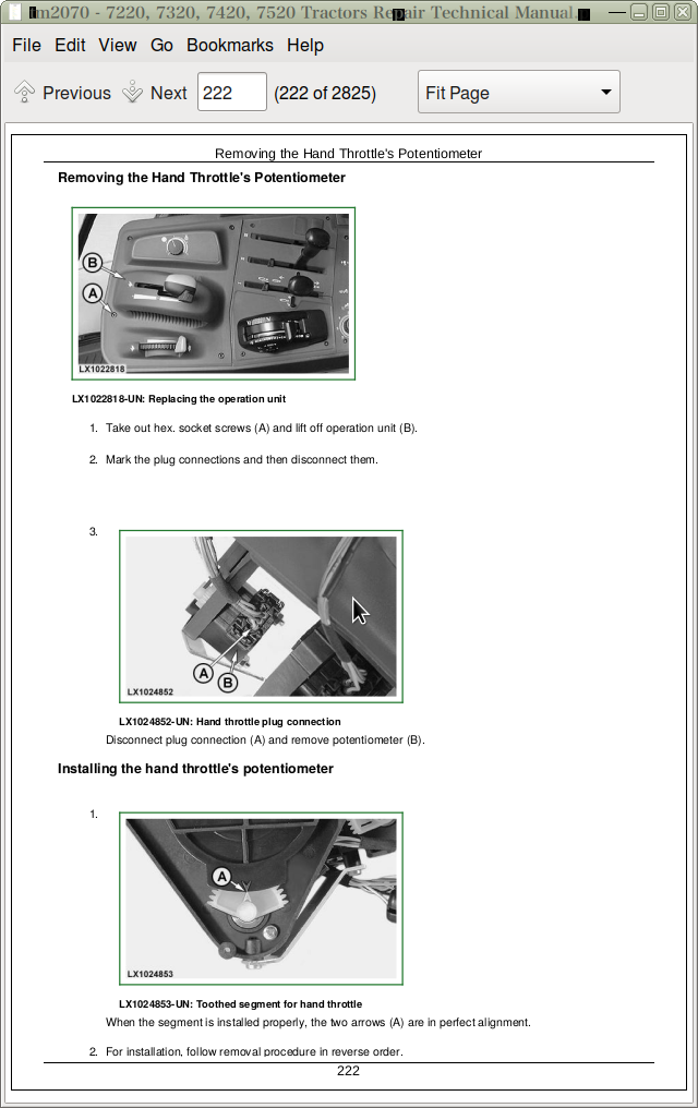
Removing the Hand Throttle's Potentiometer
Group 10: Fuel System
General Information
Remove Fuel Tank
Installing the Fuel Tank
Replace Fuel Gauge Sender
Replace Fuel Transfer Pump
Installing Check Valve in Fuel System
Replace Fuel Filter, Fuel Pump, and Bleed Fuel System
Group 15: Air Intake System
General Information
Air filter - Exploded view
Replacing Sending Unit For Air Cleaner Restriction (B02)
Group 20: Heating System
General Information
Specifications
Remove the Radiator
Change Fan Or Viscous Fan Drive
Removing and Installing the Expansion Tank
Remove And install Thermostat Valve
Install Radiator
Filling the Cooling System with Coolant
Relieving Tension on the Drive Belt
Replace Drive Belt
Replacing the Drive Belt Tensioner
Repairing the Fan Console
Group 25: Cold-Weather Starting Aid
Fuel Preheater
Electrical Starting Aid
Coolant Heater
Test Ground-Fault Circuit Interrupter
Replace Transmission Cover Heater
Replace Hydraulic Charge Pump Heater
Group 30: Exhaust System
General Information
Specifications
Install Muffler
Exhaust Pipe or Intermediate Exhaust Pipe
Exhaust Pipe or Intermediate Exhaust Pipe —Upright
Section 40: Electrical Equipment
Group 05: Electrical Connectors
Special or Essential Tools
General
Using high-pressure washers
Disconnecting electrical circuits
Stripping Wire Ends
Installing a Terminal
CINCH CINCH is a trademark of Cinch Inc. Wedgebox Connectors
CINCH CINCH is a trademark of Cinch Inc. Flexbox Connectors
WEATHER PACK Connectors
METRI PACK Connector with Terminal Lock at the Rear
METRI PACK Connector with Terminal Lock at the Front
METRI PACK Connectors
Connector at CAN Bus Terminating Resistor
Connectors for Electronic Control Units
Connector for Bosch VP44 Injection Pump
CRIMP SNAP IN connectors
Connectors
Blade Terminals
CPC Connectors
KOSTAL Connectors
DEUTSCH Connectors
Individual Terminals
Relay Socket
Fuse and Relay Boxes on Tractors with Operator's Cab
Group 10: Wiring Harnesses
Disconnecting electrical circuits
Ground Point Locations
Removing and Installing Harness W01 — Power Supply
Remove And Install Harness W02—6-Cylinder Engine, Level 1
Remove And Install Harness W02 — 6-Cylinder Engine, Level 4
Remove And Install Harness W03—Starting Aid, Level 1
Remove And Install Harness W03 — Starting Aid, Level 4
Remove And Install Harness W04 — Headlights
Remove And Install Harness W05 — Front Corner Worklights
Removing and Installing Harness W06 — Front-Wheel Drive Axle with TLS
Removing and Installing Harness W07 — Front PTO
Remove And Install Harness W08 — Cab
Remove And Install Harness W08 — Cab (AutoPowr/IVT Transmission)
Remove And Install Harness W09 — Cowl
Remove And Install Harness W09 — Cowl (AutoPowr/IVT Transmission)
Removing and Installing Harness W10 — Shift Console
Removing and Installing Harness W11 — Transmission Shift and Hand Throttle
Removing and Installing Harness W12 — Command Arm (AutoPowr/IVT transmission)
Removing and Installing Harness W13 — Clutch Sending Unit
Remove And Install Harness W14 — 3-Terminal Power Outlet Socket
Remove And Install Harness W15 — Engine Control Unit (ECU) (Level 4)
Remove And Install Harness W16 — E-SCV / E-ICV Controller (SIC) (Tier I)
Remove And Install Harness W16 — E-SCV / E-ICV Controller (SIC) (Tier II)
Removing and Installing Harness W17 — Multi-function Unit
Removing and Installing Harness W18 — Windshield Wiper Switch (with Intermittent Wipe)
Remove And Install Harness W19 — Cab Roof
Removing and Installing Harness W20 — Turn Signal and Clearance Lights
Removing and Installing Harness W21 — Worklights on Front of Cab Roof
Removing and Installing Harness W22 — Worklights on Rear of Cab Roof
Removing and Installing Harness W22 — Xenon (HID) Worklights on Rear of Cab Roof
Removing and Installing Harness W23 — Windshield Wiper (With Switch for Windshield)
Removing and Installing Harness W23 — Windshield Wiper Switch (Without Switch for Windshield)
Removing and Installing Harness W24 — Rear Window Wiper
Removing and Installing Harness W25 — Rear Window Wiper Switch
Removing and Installing Harness W26 — Fan and Air-Conditioner
Remove And Install Harness W28 — Front End Of Transmission
Remove And Install Harness W28 — Front End of Transmission (AutoPowr/IVT Transmission)
Remove And Install Harness W29 — Valve Block (AutoPowr/IVT Transmission)
Removing and Installing Harness W30 — Rear End of Transmission
Removing and Installing Harness W31 — 7-Terminal Power Outlet Socket
Remove And Install Harness W32 — Stepper Motors
Removing and Installing Harness W33 — Service
Group 15: Charging Current Circuit
Essential Tools
Specifications
Repairing the Alternator
Disconnecting Electrical Circuits
Relieving Drive Belt Tension
Remove/Install the Alternator
Pulley Remove and Install
Group 20: Starting Circuit Current
Special tools
Specifications
Repairing the Starter Motor
Disconnecting Electrical Circuits
Removing and installing the starter motor
Group 25: Fuses, Relays, And Connectors
General Information
Special Tools
Repair Specifications
Disconnecting Electrical Circuits
Fuse And Relay Boxes On Tractors With Operator's Cab
Fuse And Relay Boxes On Tractors With Operator's Cab And AutoPowr/IVT Transmission
Replacing the Main Fuses
Replace The Fuses At Electrical Starting Aid, Tractors With Level 4 Engine Control Unit (ECU)
Replace Injection Pump Fuse, Tractors With Level 4 Engine Control Unit (ECU)
Replace Starting Motor Relay, Tractors With Level 4 Engine Control Unit (ECU)
Replace Relay For Electrical Starting Aid, Tractors With Level 4 Engine Control Unit (ECU)
Replace Injection Pump Relay, Tractors With Level 4 Engine Control Unit (ECU)
Replace Main Switch
Replace Brake Switches
Replacing the Light Switch
Replace Worklight Switches
Replace Switch for Lights on Cab Frame
Replace Beacon Light Switch
Replace Hazard Warning Light Switch
Replace Switches On Multi-Function Unit
Replacing the Rear Window Wiper and Washer Switch
Replace Windshield/Rear Window Switches
Replacing the Dome Light Door Switch
Replace Front-Wheel Drive Switch
Replace Headland Management (HMS) Switch
Replace Record/Save Switch
Replace Program Switch
Replace Gear Selector Switch On Tractors With Powrquad Plus Transmissions
Replace Park Lock Switch On Tractors With Powrquad Plus Transmissions
Replacing the Fan Switch
Replacing the Switch of the Air-Conditioning System Compressor
Replace Differential Lock Switch
Replace PTO Switch
Replace Rockshaft Remote Control Switch
Replacing the Switches for the Electrical Rear-View Mirrors
Replacing the Switch for the Heated Rear-View Mirrors
Replacing the Switch for the Heated Rear Window
Replace Cruise Control Potentiometer
Rockshaft Control
Electrical Activators For Selective Control Valves (E-SCV)
Electrical Activators For Independent Control Valves (E-ICV)
Group 30: Monitoring Systems
General Information
Note
Disconnecting electrical circuits
Replace Sender For Coolant Temperature Gauge (B08)
Replace Acoustic Alarm
Replace Acoustic Alarm (Park Lock) On Tractors With AutoPowr/IVT Transmission
Group 40: Electrical Components
General Information
Specifications
Disconnecting electrical circuits
Replacing the 7-Terminal Power Outlet Socket
Replacing the Multiple Power-Outlet Socket Strip
Remove Wiper Motor
Adjusting the Headlights
Adjusting the Lights on the Cab Frame
Safety Instructions for Replacing a Halogen Bulb
Safety Instructions for Replacing Xenon (HID) Bulbs and Ballast Units
Replacing Xenon (HID) Worklights and Ballast Units
Section 53: AutoPowr/IVT Transmission (7420, 7520)
Group 00: Removing And Installing AutoPowr/IVT Transmission
Special tools
Dealer-fabricated special tools
Repair specifications
Removing The AutoPowr/IVT Transmission
Installing The AutoPowr/IVT Transmission
Group 05: Transmission Shifting Mechanisms
Reconditioning the Speed Control Lever
Reverser control, reconditioning
Reconditioning the Clutch Actuation Mechanism
Reconditioning the Manual Park Lock Release Mechanism
Releasing the Park Lock Manually
Group 10: Input Housing
Special Tools
Service Equipment and Tools
Other Material
Specifications
Installing and Removing the Vibration Damper (Repair Level 1 and 2)
Removing Clutch Control Block (Repair Level 1 and 2)
Repairing Clutch Control Block (Repair Level 1 and 2)
Installing Clutch Control Block (Repair Level 1 and 2)
Installing and Removing the Transmission Oil Filter (Repair Level 1 and 2)
Removing the System Pressure Control Block (Repair Level 1 and 2)
Installing System Pressure Control Block (Repair Level 1 and 2)
Replacing Thermostat Valve (Repair Level 1 and 2)
Replacing Filter By-Pass Valve (Cold-Weather Starting) (Repair Level 1 and 2)
Removing the Transmission Oil Pump (Repair Level 1 and 2)
Repairing the Transmission Oil Pump (Repair Level 1 and 2)
Installing the Transmission Oil Pump (Repair Level 1 and 2)
Removing and Installing Front Plate (Repair Level 1 and 2)
Separating Transmission Halves, Input/Output Housing (Repair Level 2)
Removing BG Disk Brake (Repair Level 2)
Installing BG Disk Brake (Repair Level 2)
Removing Shift Turret (Repair Level 2)
Installing Shift Turret (Repair Level 2)
Repairing Through-Drive Shaft (Repair Level 2)
Repairing P4 Planet Pinion Carrier and C3/C4 Clutch (Repair Level 2)
Repairing P4/BG Ring Gear (Repair Level 2)
Removing Hydrostatic Unit (Repair Level 2)
Installing Hydrostatic Unit (Repair Level 2)
Repairing Hydrostatic Unit Output Shaft (Repair Level 2)
Preparations for Installation of Individual Components in Input Housing (Repair Level 2)
Measuring Gaps Between Transmission Shafts in Input/Output Housing (Repair Level 2)
Joining Transmission Halves, Input/Output Housing (Repair Level 2)
Layout and Location of the Individual Transmission Sending Units
Replacing Pressure Sending Units B87, S73, S74 of System Pressure Control Block (Repair Level 1 and 2)
Replace Hydrostatic Unit Speed Sending Unit (B62) (Repair Level 1 and 2)
Group 15: Output Housing
Special Tools
Specifications
Removing Park Lock Control Block (Repair Level 1 and 2)
Replacing Park Lock Control Block Solenoids and Sensor—Later Version
Replacing Park Lock Control Block Solenoids and Sensor—Earlier Version
Repairing Park Lock Control Block (Repair Level 1 and 2)
Installing Park Lock Control Block (Repair Level 1 and 2)
Repairing Locking Pawl of Park Lock (Repair Level 1 and 2)
Removing Direction Turret and Reverse Intermediate Shaft (Repair Level 2)
Removing Hydrostatic Unit Drive Shaft (Repair Level 2)
Removing Through-Drive Shaft (Repair Level 2)
Removing Pneumatic Pump and Idler Gear (Repair Level 2)
Installing Pneumatic Pump and Idler Gear (Repair Level 2)
Installing Hydrostatic Unit Drive Shaft (Repair Level 2)
Installing Through-Drive Shaft (Repair Level 2)
Installing Direction Turret and Reverse Intermediate Shaft (Repair Level 2)
Layout and Location of the Individual Transmission Sending Units
Replacing Transmission Speed Sending Unit (B63) (Repair Level 1 and 2)
Replacing Transmission Input Speed Sending Unit (B61) (Repair Level 1 and 2)
Replacing Transmission Output Speed Sending Unit (B84) (Repair Level 1 and 2)
Replace Pressure Sending Unit (B90) for Park Lock Control Block (Repair Level 1 and 2)
Group 20: Assemble Intermediate Shaft
Specifications
Sectional View of Differential Drive Shaft
Removing the Differential Drive Shaft
Disassemble Differential Drive Shaft
Cone Point Adjustment
Assembling the Differential Drive Shaft
Section 53A: AutoPowr/IVT Transmission (7320)
Group 00: Removing and Installing the AutoPowr/IVT Transmission
Special or Essential Tools
Dealer-Manufactured Special Tools
Specifications
Removing the AutoPowr/IVT Transmission
Installing the AutoPowr/IVT Transmission
Group 05: Transmission Shift Controls
Reconditioning the Speed Control Lever
Reverser control, reconditioning
Reconditioning the Clutch Actuation Mechanism
Reconditioning the Manual Park Lock Release Mechanism
Releasing the Park Lock Manually
Group 10: Input Housing
Special Tools
Service Equipment and Tools
Other Material
Specifications
Replace Hydrostatic Unit Speed Sending Unit (B62) (Repair Level 1 and 2)
Replacing Pressure Sending Unit B87, S73, S74 (Repair Level 1 and 2)
Replacing Thermostat Valve (Repair Level 1 and 2)
Replacing Filter By-Pass Valve (Cold-Weather Starting) (Repair Level 1 and 2)
Replacing the Oil Filter (Repair Level 1 and 2)
Removing the System Pressure Control Block (Repair Level 1 and 2)
Installing System Pressure Control Block (Repair Level 1 and 2)
Removing the Transmission Oil Pump (Repair Level 1 and 2)
Repairing the Transmission Oil Pump (Repair Level 1 and 2)
Installing the Transmission Oil Pump (Repair Level 1 and 2)
Removing the Vibration Damper (Repair Level 1 and 2)
Reconditioning the Vibration Damper (Repair Level 1 and 2)
Installing the Vibration Damper (Repair Level 1 and 2)
Removing the Front Plate (Repair Level 1 and 2)
Installing the Front Plate (Repair Level 1 and 2)
Removing Clutch Control Block (Repair Level 1 and 2)
Reconditioning Clutch Control Block (Repair Level 1 and 2)
Installing the Clutch Control Block (Repair Level 1 and 2)
Separating the Input and Output Housings (Repair Level 2)
Joining the Input and Output Housings (Repair Level 2)
Removing BG Disk Brake (Repair Level 2)
Installing BG Disk Brake (Repair Level 2)
Removing Shift Turret (Repair Level 2)
Reconditioning the Shift Turret (Repair Level 2)
Installing the Shift Turret (Repair Level 2)
Removing the Hydrostatic Unit (Repair Level 2)
Installing the Hydrostatic Unit (Repair Level 2)
Reconditioning the Hydrostatic Unit Output Shaft (Repair Level 2)
Measuring the Gaps Between Transmission Shafts (Repair Level 2)
Replacing the Wiring Harness / Replacing the Fittings on the Housing (Repair Level 2)
Group 15: Output Housing
Special or Essential Tools
Specifications
Replacing Transmission Input Speed Sending Unit (B61) (Repair Level 1 and 2)
Replacing Transmission Output Speed Sending Unit (B63) (Repair Level 1 and 2)
Replace Pressure Sending Unit (B90) for Park Lock Control Block (Repair Level 1 and 2)
Replacing the Bleed Valve (Repair Level 2)
Removing the Park Lock Control Block (Repair Level 1 and 2)
Replacing Park Lock Control Block Solenoids and Sensor—Later Version
Replacing Park Lock Control Block Solenoids and Sensor—Earlier Version
Reconditioning the Park Lock Control Block (Repair Level 1 and 2)
Reconditioning the Park Lock Cam (Repair Level 1 and 2)
Installing the Park Lock Control Block (Repair Level 1 and 2)
Removing the Pneumatic Pump (Repair Level 1 and 2)
Installing the Pneumatic Pump (Repair Level 1 and 2)
Removing the Direction Turret and Reverse Intermediate Shaft (Repair Level 2)
Installing Direction Turret and Reverse Intermediate Shaft (Repair Level 2)
Removing the Drive Shaft for the Hydrostatic Unit (Repair Level 2)
Removing the Through-Drive Shaft (Repair Level 2)
Installing the Through-Drive Shaft (Repair Level 2)
Removing the Drive Gear for the Hydrostatic Unit (Repair Level 2)
Removing the Idler Gear with Pneumatic Pump Drive (Repair Level 2)
Installing the Idler Gear with Pneumatic Pump Drive (Repair Level 2)
Replacing the Screw Plugs (Repair Level 1 and 2)
Group 20: Assembling the Differential Drive Shaft
Specifications
Differential Drive Shaft — Sectional View
Disassembling the Differential Drive Shaft (without Bearings)
Reconditioning the Cover with the Park Lock Pawl
Assembling the Differential Drive Shaft (without Bearings)
Replacing the Differential Drive Shaft / Reconditioning the Bearings
Section 55: PowrQuad And Powrquad Plus Transmissions (7420, 7520)
Group 00: Install And Remove Components
Special tools
Dealer-fabricated special tools
Repair Specifications
PowrQuad Plus Transmission, Removal And Installation
Remove Powrquad Transmission
Install Powrquad Transmission
Removing the creeper transmission
Installing the Creeper Transmission
Remove Range Transmission
Install Range Transmission
Group 05: Transmission Shifting Mechanisms
Specifications
Repairing the Range Shift Linkage (PowrQuad Plus and AutoQuad Transmissions)
Check And Adjust Shift Units (Powrquad Plus Transmissions)
Repairing the Clutch Actuation (PowrQuad Plus, AutoQuad and AutoQuad Plus Transmissions)
Reconditioning the Range Shift Linkage (PowrQuad Plus and AutoQuad Transmissions) (Late Version)
Checking and Adjusting the Shift Controls/Linkages (PowrQuad Plus and AutoQuad Transmissions) (Late Version)
Group 10: PowrQuad Module
Essential or Recommended Tools
Repair Specifications
Transmission Components
Replacing the temperature sensor and pressure switches
Removing and Installing the Oil Filter Housing
Replacing the Oil Filter
Remove And Install Front Valve Housing
Removing and Installing the Valves in the Front Valve Housing
Remove And Install Front Transmission Cover
Removing and Installing the Valves in the Front Transmission Cover
Removing and Installing the Shift Valve Housing
Remove And Install Valves In Shift Valve Housing
Remove Transmission Oil Pump
Exploded View—Transmission Oil Pump
Repair Transmission Oil Pump
Install Transmission Oil Pump
Remove Gear-Shift Planetary Drive
Exploded View—Planetary Drive
Repair Gear-Shift Planetary Drive
Install Gear-Shift Planetary Drive
Remove B1 Brake Housing
Recondition B1 Brake
Install B1 Brake Housing
Remove B2-B3 Brake Housing
Recondition B2 Brake
Recondition B3 Brake
Install B2-B3 Brake Housing
Remove C4 Clutch
Cross Sectional View—C4 Clutch
Exploded View—C4 Clutch
Repair C4 clutch
Install C4 Clutch
Remove Reverse Brake
Exploded View—Reverse Brake
Repair Reverse Brake
Install Reverse Brake
Remove Forward Clutch With Planetary Drive (Forward/Reverse)
Cross Sectional View—Forward Clutch with Planetary Drive
Exploded View—Forward Clutch with Planetary Drive
Repair Forward Clutch With Planetary Drive (Forward/Reverse)
Install Forward Clutch With Planetary Drive (Forward/Reverse)
Exploded View—Output Shaft
Replace Output Shaft
Group 15: Creeper Transmission
Special tools
Repair specifications
Remove Creeper Transmission
Repair Creeper Transmission
Install Creeper Transmission
Group 20: Range Transmission
Essential or Recommended Tools
Specifications
Remove Range Transmission
Cross Sectional View—Range Box
Repair Range Transmission
Install Range Transmission
Repair Shift Cover
Replace Speed Sensor
Section 55A: PowrQuad And Powrquad Plus Transmissions (7220, 7320)
Group 00: Removal and Installation of Components
Special or Essential Tools
Dealer-Manufactured Special Tools
Specifications
PowrQuad Plus Transmission, Removal and Installation
AutoQuad Transmission, Removal and Installation
Removing the PowrQuad Transmission
Installing the PowrQuad Transmission
Removing Creeper or Option Transmissions
Installing Creeper or Option Transmissions
Removing the Range Transmission
Installing the Range Transmission
Group 05: Transmission Shift Controls
Specifications
Gear Shift Linkage, Reconditioning (Reverser Control on Steering Column)
Range Shift Linkage, Reconditioning (Reverser Control on Steering Column)
Reconditioning the Reverser Control (on Steering Column)
Adjusting the Reverse Drive Lever (Reverser Control on Steering Column)
Adjusting the Reverse Drive Linkage
Checking and Adjusting the Shift Mechanisms/Linkages (Reverser Control on Steering Column)
Repairing the Range Shift Linkage (PowrQuad Plus and AutoQuad Transmissions)
Check and Adjust the Shift Controls/Linkages (PowrQuad Plus and AutoQuad transmissions)
Adjust the Clutch Pedal (PowrQuad Transmission)
Repairing the Clutch Actuation (PowrQuad Plus, AutoQuad and AutoQuad Plus Transmissions)
Reconditioning the Range Shift Linkage (PowrQuad Plus and AutoQuad Transmissions) (Late Version)
Checking and Adjusting the Shift Controls/Linkages (PowrQuad Plus and AutoQuad Transmissions) (Late Version)
Group 10: PowrQuad Module
Essential or Recommended Tools
Other Material
Specifications
Transmission Components
Replacing the Neutral Start Circuit (with Mech. Actuated PowrQuad Module)
Replace Temperature Sensor and Pressure Switches
Removing and Installing the Oil Filter Housing
Replacing the Oil Filter
Removing and Installing the Front Valve Housing
Removing and Installing the Valves in the Front Valve Housing
Removing and Installing the Valves in the Front Valve Housing (with Mech. Actuated PowrQuad Module)
Removing and Installing Front Transmission Cover
Removing and Installing the Valves in the Front Transmission Cover
Removing and Installing the Valves in the Front Transmission Cover (with Mech. Actuated PowrQuad Module)
Removing and Installing the Shift Valve Housing
Removing and Installing the Valves in the Shift Valve Housing
Removing and Installing the Shift Valve Housing (with Mech. Actuated PowrQuad Module)
Removing and Installing the Valves in the Shift Valve Housing (with Mech. Actuated PowrQuad Module)
Remove Transmission Oil Pump
Exploded View—Transmission Oil Pump
Repair Transmission Oil Pump
Install Transmission Oil Pump
Remove Gear-Shift Planetary Drive
Exploded View—Planetary Drive
Repair Gear-Shift Planetary Drive
Install Gear-Shift Planetary Drive
Remove B1 Brake Housing
Recondition B1 Brake
Install B1 Brake Housing
Remove B2-B3 Brake Housing
Recondition B2 Brake
Recondition B3 Brake
Install B2-B3 Brake Housing
Remove C4 Clutch
Cross Sectional View—C4 Clutch
Exploded View—C4 Clutch
Repair C4 clutch
Install C4 Clutch
Remove Reverse Brake
Exploded View—Reverse Brake
Repair Reverse Brake
Install Reverse Brake
Remove Forward Clutch With Planetary Drive (Forward/Reverse)
Cross Sectional View—Forward Clutch with Planetary Drive
Exploded View—Forward Clutch with Planetary Drive
Repair Forward Clutch With Planetary Drive (Forward/Reverse)
Install Forward Clutch With Planetary Drive (Forward/Reverse)
Exploded View—Output Shaft
Replace Output Shaft
Group 15: Creeper Transmission
Specifications
Removing the Creeper Transmission
Reconditioning the Creeper Transmission
Installing the Creeper Transmission
Reconditioning the Shift Cover
Group 20: Option Transmission
Specifications
Removing the Option Transmission
Reconditioning the Option Transmission
Installing the Option Transmission
Group 25: Range Transmission
Specifications
Range Transmission - Sectional View
Removing the Range Transmission
Reconditioning the Range Transmission
Installing the Range Transmission
Reconditioning the Shift Cover
Replacing the Transmission Speed Sensor (B104)
Section 56: Drive Systems (7420, 7520)
Group 00: Removal and Installation of Components
Special or Essential Tools
Dealer-Fabricated Special Tools
Specifications
Remove Fwd Clutch
Installing the FWD Clutch
Remove Differential Housing Using JT05723 and JT05724 Universal Support Stands
Remove Differential Housing Using JT07122 Spliting Stand
Install Differential Housing
Remove Final Drives
Install Final Drives
Removing the rear PTO
Installing the rear PTO
Removing the Front PTO
Installing the Front PTO
Group 05: Universal Joint Shaft And Torsion Damper
Specifications
Remove U.J. Shaft (Front-Wheel Drive)
Reconditioning the U.j. Shaft (FWD)
Installing the U.j. Shaft (FWD)
Remove Universal Joint Shaft (Engine)
Remove And Install Ring-Shaped Cooler
Remove Torsion Damper
Changing the Torsion Damper Bearings
Installing the Torsion Damper
Install Universal Joint Shaft (Engine)
Group 10: FWD Clutch
Special tools
Other material
Repair Specifications
Front-wheel drive clutch — Sectional view
Front-Wheel Drive Clutch — Exploded View
Replacing the Sending Unit for Front-Wheel Drive Axle Speed (B89)
FWD Clutch — Replacing Solenoid Valve
Replace FWD Clutch
Group 15: Differential
Special tools
Specifications
Remove Differential
Disassemble Differential
Differential — Exploded view
Assembling the differential
Install Differential
Group 20: Hydraulic Pump Drive
Special tools
Repair specifications
Remove And Disassemble Pump Drive Pinion Gear
Removing And Disassemble Pump Drive Gear
Assemble And Install Pump Drive Gear
Assembling and installing the pump drive pinion
Check And Adjust Pump Drive Pinion Backlash
Group 25: Final Drives
Special Tools
Other Material
Specifications
Repair Instructions
Remove Planetary Carrier
Disassemble Planet Pinion Carrier
Assemble Planet Pinion Carrier
Remove Axle Housing
Disassemble and Assemble Axle Housing
Disassemble and Assemble Axle Shaft
Install Axle Housing
Install Planet Pinion Carrier And Check Rolling Drag Torque (Non-Shimmed Axles)
Install Planet Pinion Carrier And Check Rolling Drag Torque (Shimmed Axles)
Group 30: Hi-Crop Final Drive (7420)
Service Tools
Other Material
Specifications
General Repair Procedures—Hi-Crop Final Drive
Cross-Sectional View—Hi-Crop Final Drive
Remove Final Drive
Disassemble Final Drive
Assemble Final Drive
Install Final Drive
Group 35: Hi-Crop MFWD (7420)
Service Tools
Specifications
Cross-Sectional View—Planetary Carrier and Wheel Hub
Remove, Recondition, And Install Planetary Carrier And Wheel Hub
Assemble And Install Planetary Carrier And Wheel Hub
Cross-Sectional View—Knuckle Spindle Assembly
Disassemble, Inspect, and Assemble Knuckle Spindle Assembly
Install MFWD Axle Into Repair Stand
Cross-Sectional View—Planetary Carrier-Wheel Hub-Knuckle Spindle-U-Joint/Axle Shaft Assembly
Remove And Install Planetary Carrier-Wheel Hub-Knuckle Spindle-U-Joint/Axle Shaft Assembly
Determine Kingpin Shim Pack
Remove Differential Housing
Cross-Sectional View—Differential Housing
Repair Differential Housing
Assemble Differential
Cross-Sectional View—Differential Drive Shaft and Input Quill
Remove And Disassemble Differential Drive Shaft
Determine Differential Drive Shaft Cone Point Shim Pack
Assemble And Install Differential Drive Shaft
Check Ring Gear Backlash And Determine Differential Case Bearing Cup Shim Pack
Adjust Ring Gear Backlash
Backlash Shim Pack Example and Worksheet
Install Differential Case Bearing Cup and Differential Housing
Disassemble And Assemble Axle Housing
Determine And Install Axle Housing Bearing Cup Shim Pack
Bearing Cup Shim Pack Procedure
Preload Shim Pack Example And Worksheet
Install Axle Housing
Cross-Sectional View—Steering Cylinder Housing Assembly
Remove And Disassemble Steering Cylinder
Cross-Sectional View—Steering Cylinder
Assemble And Install Steering Cylinder
Replace MFWD Pivot Bushing
Group 40: Rear PTO
Special tools
Specifications
Repair Instructions
Repair Rear PTO
Remove and Disassemble Countershaft
Assemble And Install Countershaft
Remove And Disassemble Output Shaft
Assemble And Install PTO Output Shaft
Remove PTO Shifter
Install PTO Shifter
Replacing Oil Seal on PTO Output Shaft
Remove Modulating Valve
Disassemble and Assemble Modulating Valve
Install Modulating Valve
Changing and adjusting the bowden cable
Section 56A: Drive Systems (7220, 7320)
Group 00: Removal and Installation of Components
Special or Essential Tools
Dealer-Fabricated Special Tools
Specifications
Removing the FWD Clutch
Installing the FWD Clutch
Remove Differential Housing Using JT05723 and JT05724 Universal Support Stands
Remove Differential Housing Using JT07122 Splitting Stand
Installing the Differential Housing
Removing the Final Drives
Installing the Final Drives
Removing the Rear PTO
Installing the Rear PTO
Removing the Front PTO
Installing the Front PTO
Group 05: U-Jointed Shafts and Torsion Damper
Specifications
Remove U.J. Shaft (Front-Wheel Drive)
Reconditioning the U.j. Shaft (FWD)
Installing the U.j. Shaft (FWD)
Removing The Universal Joint Shaft (Engine)
Removing and Installing the Ring-Shaped Cooler
Removing the Torsion Damper
Changing the Torsion Damper Bearings
Installing the Torsion Damper
Installing The Universal Joint Shaft (Engine)
Group 10: Front-Wheel Drive Clutch
Special Tools
Other Material
Specifications
Replacing the Sending Unit for Front-Wheel Drive Axle Speed (B89)
Disassembling the Front Wheel Drive Clutch
Front-Wheel Drive Clutch — Exploded View
Assembling the Front-Wheel Drive Clutch
Group 15: Differential
Specifications
Removing the Differential
Differential — Exploded View
Disassembling the Differential
Assembling the Differential
Differential - Exploded View (Late Version)
Recondition the Differential (Late Version)
Installing the Differential
Group 20: Hydraulic Pump Drive
Specifications
Reconditioning the Hydraulic Pump Drive
Adjusting the Hydraulic Pump Drive
Group 25: Final Drives
Special or Essential Tools
Specifications
Reconditioning the Final Drives
Group 30: Rear PTO Options
Special Tools
Dealer-Fabricated Special Tools
Other Material
Specifications
Replacing the Output Shaft Seal Ring
Replacing the O-Ring on a Reversible PTO
Removing the PTO Clutch
Reconditioning the PTO Clutch
Installing the PTO Clutch
Reconditioning the PTO Brake
Disassembling the PTO Drive Train
Reconditioning the Output Shaft (540/1000 rpm Reversible and Shiftable)
Assembling the Output Shaft (540/1000 rpm and 540/540E/1000 rpm Shiftable)
Reconditioning the Countershaft (540/1000 rpm and 540/540E/1000 rpm)
Assembling the PTO Shifter (540/1000 rpm Shiftable and 540/540E/1000 rpm)
Assembling PTO Drive Train
Adjusting Taper Roller Bearing at Output Shaft
Adjusting the Taper Roller Bearing of the Countershaft
Installing the Support and Adjusting the Taper Roller Bearings
Installing the PTO Housing
Removing the PTO Modulating Valve
Reconditioning the PTO Modulating Valve
Installing the PTO Modulating Valve
Repairing the Solenoid Valve
Replacing the PTO Speed Sending Unit
Changing and Adjusting the Bowden Cable
Group 35: Front PTO
Other Material
Specifications
General Repair Procedures
Replacing the Solenoid Valve
Reconditioning the Modulator Valve
Replacing the Front PTO Speed Sending Unit (B58)
Cleaning and Replacing the Filter
Reconditioning the Pressure-Regulating Valve
Checking the Cooler Relief and Filter By-Pass Valves
Removing and Installing the Valve Plate
Front PTO — Sectional View
Disassembling the Front PTO
Reconditioning the Oil Pump
Reconditioning the PTO Clutch
Reconditioning the PTO Brake
Reconditioning the Intermediate Gear Shaft (PTO Rotating Counterclockwise)
Reconditioning the Drive Shaft
Assembling the Front PTO
Section 60: Steering And Brakes
Group 05: Hydrostatic Steering
Special Tools
Specifications
Preliminary Work
Disconnect/Connect Steering or Brake Hoses
Remove Steering Column and Steering Valve
Disassembling the Steering Valve
Exploded View of Steering Valve
Assembling the Steering Valve
Adjusting the Shock Valves
Steering Wheel and Steering Column (With Cab)
Recondition the Steering Column
Install Steering Column and Steering Valve
Group 10: Brake Valve
Special Tools
Specifications
General Repair Procedures—Brake Valve
Remove and Install Accumulator
Brake Valve (With Power Fill)
Power-Fill Brake Valve with MFWD and Disk Brake
Group 15: Rear Wheel Brakes
Specifications
Preliminary Work
Removing the Rear Brakes
Rear Brakes—Exploded View
Repairing the Rear Brakes
Install Rear Brakes
Final Assembly
Bleed Brakes (Brake Valve With Power-Fill Brakes, MFWD And Disk Brake)
Section 70: Hydraulic System
Group 05: Control Elements
Specifications
Selective Control Valves — Remove And Install Actuating Elements
Selective Control Valves — Adjusting the Bowden Cable
Remove and Install Multifunction Lever
Adjust the Multifunction Lever (Shift Console)
Group 10: Hydraulic Pump And Charge Pump
Other Material
Specifications
Remove And Install Charge Pump
Recondition Charge Pump
Charge Pump - Check Lube Oil Valve
Hydraulic Oil Reservoir — Restrictor
Hydraulic Pump — Remove And Install Pressure-And-Flow Controller
Hydraulic Pump — Recondition Pressure-And-Flow Controller
Remove And Install Hydraulic Pump
Recondition Hydraulic Pump
Group 15: Valves
Special or Essential Tools
Special Tools
Special Tools (Dealer Fabricated)
Hydraulic System — General Instructions on Safety and Repair
Direct Control of Rockshaft
Remove Rockshaft Valve
Recondition Rockshaft Valve
Rockshaft Valve — Depth To Which Raising And Lowering Valves Are Installed
Rockshaft Valve — Remove and Install Stepper Motor
Rockshaft Valve — Centering Stepper Motor
Install Hitch Valve
Remove Main Block
Recondition Main Block
Install Main Block
Recondition Hydraulic Oil Filter
Group 20: Rockshaft (7420, 7520)
Other Material
Repair specifications
Rockshaft — Remove And Install Electronic Control Unit
Hitch — Remove And Install Position Sensor And Toothed Segment
Hitch — Remove And Install Lift Shaft
Hitch — Remove Lift Shaft Cylinders
Hitch — Repair Lift Cylinder
Hitch — Installing the lift cylinders
Hitch — Remove And Install Draft Load Potentiometer And Draft Link Support
Group 20A: Rockshaft (7220, 7320)
Special or Essential Tools
Self-Manufactured Special Tools
Other Material
Specifications
Rockshaft — Remove And Install Electronic Control Unit
Rockshaft — Remove And Install Position Sensor And Toothed Segment
Rockshaft — Remove And Install Rockshaft
Rockshaft — Remove Rockshaft Cylinders
Rockshaft — Recondition Rockshaft Cylinders
Rockshaft — Installing the Rockshaft Cylinders
Rockshaft — Remove And Install Draft Sensors And Draft Link Bearing Pins
Group 25: Additional Control Units And Reception Couplings
Special Tools (Dealer Fabricated)
Other Material
Repair Specifications
Recondition Selective Control Valves And Couplers — General Instructions On Safety And Reconditioning
SCV Identification
Install Shuttle Valves
Remove Selective Control Valves
Series 100 Selective Control Valves — Repair
Series 200/300 Selective Control Valves (Mechanically Actuated) — Replace Control Knobs
Series 200/300 selective control valves (mechanically actuated) — Inspecting the check valves
Series 200/300 selective control valves (mechanically actuated) — Inspecting the inlet check valve and metering valve
Series 200 Selective Control Valves — Repairing
Series 300 selective control valves (mechan actuated) — Inspecting the pressure compensator valve
Series 300 Selective Control Valves (Mechan Actuated) — Repairing
Series 300 Selective Control Valves (Electrically Actuated) — Inspecting the Check Valves
Series 300 Selective Control Valves (Electrically Actuated) — Inspecting the Inlet Check Valve
Series 300 Selective Control Valves (Electrically Actuated) — Inspecting the Pressure Compensator Valve
Series 300 Selective Control Valves (Electrically Actuated) — Reconditioning
Install Selective Control Valves
Selective Control Valves — Install Endplate
Selective Control Valves — Recondition Couplers
Group 30: Independent Control Valve
Other Material
Specifications
Remove Independent Control Valve (ICV)
Recondition Independent Control Valve
Independent Control Valve — Recondition Inlet Plate
Assemble Independent Control Valve
Install Independent Control Valve
Section 80: Miscellaneous
Group 00: Remove And Install Components
Special Tools
Dealer-Fabricated Special Tools
Repair specifications
Remove Main Frame
Install Main Frame
Remove Front Wheel Drive Axle
Install Front-Wheel Drive Axle
Remove FWD Axle With TLS
Install Front-Wheel Drive Axle With TLS
Remove Front Axle Support
Install Front Axle Support
Group 05: Main Frame (7420, 7520)
Repair specifications
Repair Main Frame
Group 80A: Main Frame (7220, 7320)
Removing Main Frame
Installing Main Frame
Group 10: Front And Rear Wheels
Special tools
Repair Specifications
Removing the Front and Rear Wheels
Install Front And Rear Wheels
Group 20: Axle Suspension Of TLS Front Wheel Drive Axle
Special or Essential Tools
Other material
Repair Specifications
Relieving Pressure in the Hydraulic System
Remove/Install Oscillation Limiter
Remove Panhard Link
Install Panhard Link
Remove And Install Sensor Rod
Remove Position Sensor
Recondition Position Sensor
Install Position Sensor
Remove Hydraulic Cylinder
Repair Hydraulic Cylinder
Installing Hydraulic Cylinder
Remove Control Valve Block
Recondition Control Valve Block Valves
Installing the Control Valve Block
Remove Accumulator
Recondition Accumulator
Install Accumulator
Remove And Repair Bearing Support
Installing the bearing support
Section 90: Operator's Cab
Group 00: Installing And Removing Components
Special Or Essential Tools
Dealer-Manufactured Special Tools
Repair specifications
Tilt Operator's Cab Upward
Tilt Operator's Cab Downward
Remove Operator's Cab
Install Operator's Cab
Check And Adjust Shift Units
Group 05: Controls And Instruments
Replace Bulbs On Instrument Unit
Removing Control Unit
Removing Control Unit for the Lighting System
Replace Control Unit (BCU)
Replace Control Unit (SFA)
Replace Control Unit (SIC)
Replace Control Unit (ECU)
Replace Control Unit (UIC/PLC)
Replace Terminating Bus Resistors
Replace Performance Monitor (PRF)
Replace Instrument Unit (BIF)
Group 10: Air Conditioning System
Essential or Recommended Tools
Other Material
Service Parts Kits
Specifications
Hose and Tubing O-Ring Connection Torques
Air Conditioning System—Diagram
Air Conditioning System Fitting—Reference Chart
Discharge Air Conditioning System
Remove and Install Compressor
Test Volumetric Efficiency
Test Shaft Seal Leakage
Disassemble and Assemble Compressor Clutch
Check Clutch Hub Clearance
Inspect Compressor Manifold
Inspect Compressor Thermal Bypass Valve
Disassemble, Inspect, and Assemble Compressor
Remove and Install Compressor Relief Valve
Replace Receiver-Dryer
Leak Test Condenser
Leak Test Evaporator
Remove and Install Expansion Valve
Flushing, Purging, and Evacuating Information
Flush Air Conditioning System
Purge Air Conditioning System
Evacuate Air Conditioning System
Refrigerant Oil Information
Check Compressor Oil Charge
Determine Correct Refrigerant Oil Charge
Add Refrigerant Oil to System
Add Refrigerant Oil to Pressurized System
Charge Air Conditioning System
Removing and Installing the Thermostat Switch
Adjusting Thermostat Switch Bowden Cables
Removing and Installing the High/Low Pressure Switch
Group 15: Heating System
Removal and Installation of Components
Group 20: Seats
Repair Specifications
Comfort seat MSG85
Air Comfort Seat MSG95, Lower Section
Exploded view of the passenger seat
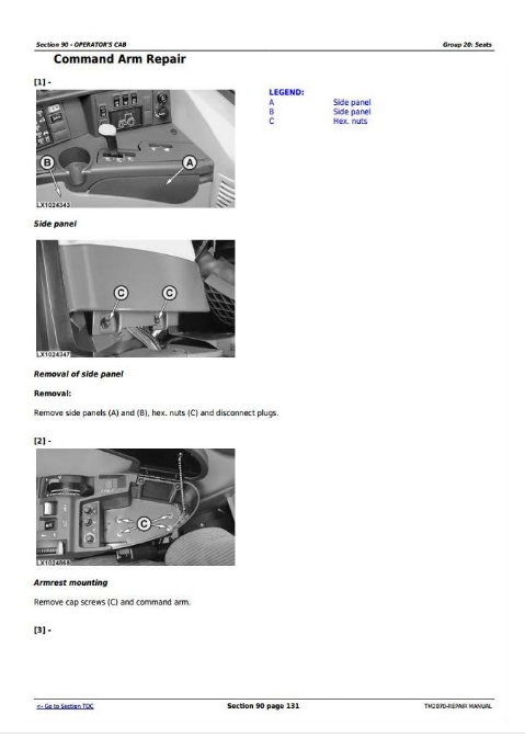
Command Arm Repair
Group 25: Operator's Cab
Remove Cab Frame
Cab Mounting Torques
Removing the Outer Roof
Remove And Install Windshield
Remove And Install Rear Window
Installing Door Lock
Adjusting Window Contact Pressure
Operator's Cab Door Removal And Installation
Roller Sun-Visor Removal and Installation
Removing Inner Roof Trim
Group 30: Components Of The Electronic Hitch Control
Disconnecting electrical circuits
Service Information
Replacing Control Unit (BCU)
Replacing The Operation Unit
Group 35: Cab Suspension
Important Instructions
Specifications
Relieving Hydraulic System Pressure
Installing and Removing the Cab Suspension Shields
Removing and Installing the Sensor Rod
Adjusting the Sensor Rod
Removing the Position Sensor
Reconditioning the Position Sensor
Installing the Position Sensor
Removing the Accumulator
Reconditioning the Accumulator
Installing the Accumulator
Removing Hydraulic Cylinder
Installing Hydraulic Cylinder
Removing the Control Valve Block
Reconditioning the Valves in the Control Valve Block
Installing the Control Valve Block
Panhard Link Removal and Installation
Bleeding Cab Suspension Hydraulic Cylinders
Section 99: Special tools (dealer- fabricated)
Group 05: Special tools (dealer- fabricated)
Adapter Strut
Holding Device
Adapter
Suspension Eyes For Operator's Cab
Holding Device
DFRW79—Piston Holding Tool
DFRW139—Evaporator Flushing Block
Socket Wrench Insert
Driver
DFRW29—Final Drive Housing Adapter
DFRW164—Axle Adjusting Tool
Bushing
Socket Wrench Insert
Special Wrench
Installation Tool
Tube
Unlocking Device
Suspension Device
DFRW185—580 mm Precision Bridge Tool
DFRW186— 70 mm Parallel Blocks
DFRW187—285 mm Precision Bridge Tool
John Deere Tractors 7220, 7320, 7420, 7420 Hi-Crop, 7520 2-Wheel Drive Repair Service Manual (TM2070)
![]()