
John Deere 7405 Tractor Repair Service Manual (TM6014)
Complete Repair Service Technical Manual for John Deere 2WD or MFWD Tractors 7405, with all the workshop information to maintain, repair, and rebuild like professional mechanics.
John Deere 7405 Tractor workshop technical manual (repair) includes:
* Numbered table of contents easy to use so that you can find the information you need fast.
* Detailed sub-steps expand on repair procedure information
* Numbered instructions guide you through every repair procedure step by step.
* Notes, cautions and warnings throughout each chapter pinpoint critical information.
* Bold figure number help you quickly match illustrations with instructions.
* Detailed illustrations, drawings and photos guide you through every procedure.
* Enlarged inset helps you identify and examine parts in detail.
tm6014 - 7405 tractor Technical Manual - Repair.pdf
tm6014 - 7405 tractor Technical Manual - Repair.epub
PRODUCT DETAILS:
Total Pages: 1,115 pages
File Format: PDF/EPUB/MOBI/AZW (PC/Mac/Android/Kindle/iPhone/iPad; bookmarked, ToC, Searchable, Printable)
Language: English
MAIN SECTIONS
Foreword
Safety
Safety Measures
General Information
Specifications
Fuel and Lubricants
Engine
Engine Removal and Installation
Engine Repair
Fuel, Air Intake and Cooling Systems
Speed Control
Fuel System
Air Intake System
Cooling System
Cold Weather Starting Aids
Electrical System
Connectors
Wiring Harnesses
Charging Circuit
Starting Motor Circuit
Switches, Relays and Solenoids
Monitoring System
Auxiliary Lighting and Electrical Components
Powrquad Transmission
Removal and Installation of Transmission Components
Transmission Controls
PowrQuad Module
Creeper Transmission
Range Transmission
Drive Systems
Component Removal and Installation
U-Jointed Shafts and Torsion Damper
Front Wheel Drive Clutch
Differential
Final Drives
Rear PTO
Hydraulic Pump Drive
Steering and Brakes
Hydrostatic Steering
Brake Valve
Rear Wheel Brakes
Hydraulic System
Controls
Hydraulic Pump
Hydraulic System Valves
Three Point Hitch
Selective Control Valves and Couplers
Bleed Hydraulic System
Miscellaneous
Component Removal and Installation
Main Frame
Front and Rear Wheels
Front and Rear Wheels
Seat/Deluxe
Deluxe Seat
Special Tools
tm6014 - 7405 tractor
Table of Contents
Foreword
Section 05: Safety
Group 05: Safety Measures
Safety Information
“Important” - Information
“Note” - Information
Handle Fluids Safely-Avoid Fires
Prevent Battery Explosions
Prepare For Emergencies
Prevent Acid Burns
Avoid High-Pressure Fluids
Park Machine Safely
Support Machine Properly
Wear Protective Clothing
Work In Clean Area
Service Machines Safely
Work In Ventilated Area
Illuminate Work Area Safely
Replace Safety Signs
Use Proper Lifting Equipment
Avoid Heating Near Pressurized Fluid Lines
Remove Paint Before Welding or Heating
Keep Rops Installed Properly
SERVICE TIRES SAFELY
Practice Safe Maintenance
Use Proper Tools
Dispose of Waste Properly
Live With Safety
Service Front-Wheel Drive Tractor Safely
Section 10: General Information
Group 05: Specifications
General Specifications
Sealants and Adhesives Cross-Reference Chart
Glossary of Terms
Metric Bolt and Cap Screw Torque Values
Unified Inch Bolt and Cap Screw Torque Values
Group 10: Fuel and Lubricants
Diesel Fuel Specifications
Lubricity of Diesel Fuel
Diesel Fuel Storage
Do Not Use Galvanized Containers
Fill Fuel Tank
Diesel Engine Oil
Engine Break - In Oil
Engine Cooling System
Liquid Coolant Conditioner
Transmission-Hydraulic Oil
MFWD Gear Oil
Grease (Specific Application)
Grease
Alternative and Synthetic Lubricants
Lubricants Storage
Section 20: Engine
Group 00: Engine Removal and Installation
Special or Essential Tools
Repair Engine-Use CTM104
Specifications
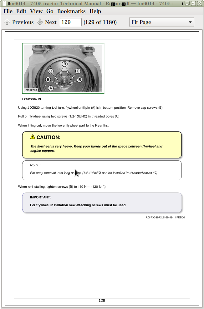
Removing Engine
Installing Engine
Replacing Engine Mountings
Front Engine Mountings
Rear Engine Mountings
Group 05: Engine Repair
Engine Repair - Use CTM 104
Access to Intake and Exhaust Valves
Access to Front Crankshaft Seal
Access to Rear Crankshaft Seal - W/Creeper
Access to Rear Crankshaft Seal-W/O Creeper
Access to Camshaft
Access to Timing Gear Cover
Remove and Install Engine Valve Cover
Section 30: Fuel, Air Intake and Cooling Systems
Group 05: Speed Control
Specifications
Adjusting Throttle Hand Lever
Adjusting Throttle Control
Group 10: Fuel System
General Information
Removing Fuel Tank
Installing Fuel Tank
Replace Fuel Gauge Sending Unit
Replace Fuel Filter, Fuel Pump and Bleed Fuel System
General Information
Group 15: Air Intake System
Service Air Intake System
Air Intake System
Group 20: Cooling System
General Information
Specifications
Removing Radiator
Replacing Fan and Fan Drive
Installing Radiator
Inspect Belt Tensioner
Replace Belt Tension Mechanism
Replacing Drive Belt
Drive Belt Tensioner - Exploded View
Group 25: Cold Weather Starting Aids
Fuel Preheater
Electric Starting Aid
Coolant Heater
Section 40: Electrical System
Group 05: Connectors
Special or Essential Tools
Disconnecting Electrical Circuit
Metri Pack Connector METRI PACK is a trade name of the PACKARD ELECTRIC Company
Weather Pack Connector WEATHER PACK is a trade name of the PACKARD ELECTRIC Company
Crimp Snap in Connector CRIMP SNAP IN is a trade name of the AMP Company
CPC ConnectorCPC is a trade name of the AMP Company
Replace Load Center Connector
Replace Power Distribution Center Connectors
Replacing Female Terminal on 45-Pin Plug
Installing Terminal
Changing Terminals
Stripping Wire Ends
Installing Terminal
Group 10: Wiring Harnesses
GROUND POINT LOCATIONS
Removing and Installing Main Wiring Harness
Removing and Installing Hitch Wiring Harness
Removing and Installing PTO Wiring Harness
Group 15: Charging Circuit
Repair Alternator-Use CTM77
General
Specifications
Removing Alternator
Group 20: Starting Motor Circuit
Special or Essential Tools
Specifications
Repair Starter-Use CTM77
Removing Starting Motor
Replace Starter Circuit Relay
Replace Fusible Link
Replace Neutral Start Switch - Powrquad Transmission
Group 25: Switches, Relays and Solenoids
Disconnecting Electrical Circuit
Specifications
Replace Brake Switch
Replace MFWD Solenoid
Replace MFWD Switch
Replace Differential Lock and Rear PTO Solenoids
Differential Lock Switch
Replace PTO Switch
Replacing the Sensitivity Potentiometer
Replace Hitch Control Potentiometer and Switch
Replacing Draft Sensor
Replace Install Hitch Position Sensor
Location of Hitch Position Sensor
Replace Fuel Shut-Off Solenoid
Replace Main Switch
Operating Lights
Main Fuse
Replace Thermo Starting Aid and Heater Relay
Load Center
Group 30: Monitoring System
Service Equipment and Tools
Other Material
Specifications
Disconnecting Electrical Circuit
Replacing PTO Speed Sending Unit
Replacing Engine Oil Pressure Sending Unit
Replacing Engine Speed Sending Unit
Replacing Air Cleaner Sending Unit
Replacing Coolant Temperature Sending Unit
Replace Fuel Gauge Sending Unit
Temperature and Pressure Sending Units
Removing Instrument Unit
Remove and Install Draft Link Sensor
Adjust Draft Link Sensor
Group 40: Auxiliary Lighting and Electrical Components
Replace Seven-Terminal Outlet Socket
Section 55: Powrquad Transmission
Group 00: Removal and Installation of Transmission Components
Special or Essential Tools
Specifications
Removing Powrquad Module
Installing Powrquad Module
Removing The Creeper Transmission
Installing Creeper Transmission
Removing The Range Transmission
Installing Range Transmission
Group 05: Transmission Controls
Essential or Recommended Tools
Shift Console Access
Specifications
Gear Shift Linkage
Gear Shift Linkage (Cont.)
Range Shift Linkage
Range Shift Linkage (Cont...)
Installing Bowden Cables
Adjusting Reverser Drive Linkage
Adjusting Shift Linkage
Adjusting Parking Lock
Remove Shift Control Assembly PowrQuad
Disassemble Shift Control Assembly
PowrQuad Shift and Park Linkage Assembly
Shift and Park Linkage Symptom/Cause Chart
Shift and Park Linkage Adjustment
Preliminary Checks
Check Shifter Lever Tang and Fork Slot
Check Shift Lever Pivot
Inspect Shifter Cams
Check and Adjust Cam Neutral Alignment
Check and Adjust Park Disengaged Stop (After Cam Adjustment)
Inspect and Adjust FNR Lower Rod
Inspect and Adjust FNR Linkage (Upper and Lower)
Inspect and Adjust Lower Speed Linkage
Inspect and Adjust Upper Speed Linkage
Inspect Lower Park Rod
Inspect Upper Park Rod and Check Park Adjustment
Adjust Park Rod
Adjust Park Rod with Turnbuckle
Adjust Park Rod with Balljoint
Check Park Rod for Excessive Flexing
Check Park Disengaged Stop
Lubricate Park Arm, Shifter Fork Slots and Shift Lever Tang
Inspect and Adjust Range Shift Linkage
Drive and Final Checks-Shifting and Park Performance
Other Symptoms and Solutions
Exploded View
Disassemble
Assemble
Adjust or Replace Clutch Cable
Group 10: PowrQuad Module
Special or Essential Tools
Service Equipment and Tools
Other Material
Specifications
Repair Instructions
General Repair Procedures-PowrQuad Transmission
Transmission Components
Install Transmission in Repair Stand
Remove Transmission Front Cover/Front Valve Housing
Remove Front Valve Housing
Front Valve Housing Valves
Transmission Front Cover Valves
Traction Clutch Valve
Replace Traction Clutch Valve Shifter Lever/Shaft Seal
Replace Traction Clutch Valve Inner Arm/Shaft
Transmission Pump-Cross-Sectional View
Repair Transmission Pump
Install Front Valve Housing
Install Transmission Front Cover/Front Valve Housing
Remove Shift Control Valve Housing
Replace Forward-Reverse/Speed Selector Shifter Levers/Shaft Seals
Replace Forward-Reverse/Speed Selector Shifter Shafts/Shifter Arms
Shift Control Valve Housing Valves
Modulator Valve-Cross-Sectional View
Planetary Housing Valves
Forward/Reverse Control Valve-Cross-Sectional View
Speed Selector Valve-Cross Sectional View
Assemble and Install Shift Valve Housing
Disassemble Planetary Assembly
Recondition Input Planetary Carrier
Disassemble Input Planetary Assembly
Disassemble Reverse Brake Housing Components
Reverser Carrier/Traction Clutch Assembly-Cross-Sectional View
Recondition Reverser Carrier/Traction Clutch Assembly
Disassemble Planetary Housing Components
Direct Drive Clutch Assembly-Cross-Sectional View
Recondition Direct Drive Clutch Assembly
Assemble Planetary Housing Components
Assemble Reverse Brake Housing Components
Assemble Planetary/Reveerse Brake Housing Assembly
Assemble Input Planetary Assembly
Group 15: Creeper Transmission
Special or Essential Tools
Specifications
Preliminary Work
General Repair Procedures - Creeper Transmission
Recondition Creeper Transmission
Creeper Transmission-Cross-Sectional View
Shifter Components-Cross-Sectional View
Removing Shifter Components
Input/Output Drive Shaft - Component
Countershaft and Housing - Components
Remove Input/Output Drive Shaft Assembly
Disassemble and Assemble Drive Shaft/Snubber Brake
Remove and Install Countershaft
Install Input/Output Shaft Assembly
Final Assembly
Group 20: Range Transmission
Special or Essential Tools
Service Equipment and Tools
Specifications
General Repair Procedures - Range Box
Repair Instructions
Preliminary Work
Range Box Transmission
Shifting Mechanism - Cross-Sectional View
Removing Differential Drive Shaft
Removing Drive Shaft
Differential Drive Shaft - Exploded View
Drive Shaft - Exploded View
Shifting Mechanism - Exploded View
Parking Lock - Exploded View
Repairing Drive Shaft
Installing Drive Shaft
Adjusting Drive Shaft End Play
Installing Differential Drive Shaft and Adjusting Cone Point
Adjusting End Play of Differential Drive Shaft
Adjusting Shifting Mechanism
Repairing and Installing Shift Cover
Final Assembly
Section 56: Drive Systems
Group 00: Component Removal and Installation
Special or Essential Tools
Specifications
Removing Differential Housing
Installing Differential Housing
Removing PTO Housing
Installing PTO Housing
Removing Final Drives
Installing Final Drives
Installing Front-Wheel Drive Clutch
Group 05: U-Jointed Shafts and Torsion Damper
Specifications
Removing U.J. Shaft (MFWD)
Installing U.J. Shaft (MFWD)
Removing U.J. Shaft (Engine)
Removing Torsion Damper
Changing Torsion Damper Bearing
Installing Torsion Damper
Installing U.J. Shaft (Engine)
Disassemble Universal Joint Drive Shaft
Assembling Joint Drive Shaft
Group 10: Front Wheel Drive Clutch
Special or Essential Tools
Service Equipment and Tools
Specifications
Repair Instructions
Preliminary Work
Front Wheel Drive Clutch - Cross Sectional View
Removing Clutch
Disassemble MFWD Clutch
Front Wheel Drive Clutch Components
Assembling Clutch
Installing Clutch
Adjusting End Play
Adjusting Brake Band
Final Assembly
Group 15: Differential
Special or Essential Tools
Service Equipment and Tools
Specifications
Repair Instructions
Preliminary Work
Removing Differential
Disassembling Differential
Exploded View
Assembling Differential
Installing Differential
Adjusting Differential Preload
Adjusting Backlash
Final Assembly
Group 20: Final Drives
Special or Essential Tools
Service Equipment and Tools
Other Material
Specifications
Repair Instructions
General Repair Procedures - Final Drive
Preliminary Work
Remove Planet Pinion Carrier
Final Drive-Cross-Sectional View 86 mm Diameter Axle Shaft
Disassemble Planet Pinion Carrier
Planet Pinion Carrier-Exploded View
Assemble Planet Pinion Carrier
Remove Axle Housing
Disassemble and Assemble Axle Housing
Disassemble and Assemble Axle Shaft
Install Axle Housing
Install Planet Pinion Carrier and Check Rolling Drag Torque
Final Assembly
Group 25: Rear PTO
Special or Essential Tools
Service Equipment and Tools
Specifications
General Repair Procedures-PTO
Clutch
Repair PTO
PTO Clutch-Cross-Sectional View
Remove and Disassemble PTO Clutch
Assemble and Install PTO Clutch
Remove and Disassemble Countershaft
PTO Countershaft-Cross-Sectional View
Assemble and Installing
Two Speed PTO Output Shaft-Cross-Sectional View
Remove and Disassemble Output Shaft
Assemble and Install PTO Output Shaft
Replace PTO Brake
Replacing Oil Seal on PTO Output Shaft
Remove Valve Housing
Disassemble and Assemble Valve Housing
Install Valve Housing
Group 35: Hydraulic Pump Drive
Special or Essential Tools
SERVICE EQUIPMENT AND TOOLS
Specifications
HYDRAULIC PUMP DRIVE-CROSS-SECTIONAL VIEW
Remove and Disassemble Pump Drive Pinion Gear
Remove and Disassemble Pump Drive Gear
Assemble and Install Pump Drive Gear
Assemble and Install Pump Drive Pinion
Section 60: Steering and Brakes
Group 05: Hydrostatic Steering
Special or Essential Tools
Specifications
Removing Steering Valve
Removing Steering column and Steering Valve
Removing Instrument Unit
Remove Front steering cover
Disassembling Steering Valve
Exploded View of Steering Valve
Assembling Steering Valve
Adjusting Double-Acting Shock Valves
Attachments Controls
Repairing Steering Column
Installing Steering Valve
Installing Steering Column and Steering Valve
Installing Front steering cover
Group 10: Brake Valve
Service Parts Kits
Specifications
General Repair Procedures-Brake Valve
Remove and Install Brake Valve
Bleed Brakes
Check Manual Brakes
Group 15: Rear Wheel Brakes
Specifications
Preliminary Work
Removing Rear Wheel Brakes
Rear Wheel Brakes - Exploded View
Repairing Brakes
Installing Rear Brakes
Final Assembly
Bleeding Brakes
Section 70: Hydraulic System
Group 05: Controls
General Information
Connecting the Bowden Cable
SCV Actuating Elements
Adjusting Bowden Cable
Installing Multi-Function Lever
Adjusting Multi-Function Lever
Group 10: Hydraulic Pump
Other Material
Specifications
Repair Instructions
Removing Hydraulic Pump
Installing Hydraulic Pump
Group 15: Hydraulic System Valves
Special or Essential Tools
Service Parts Kits
Specifications
General Repair Procedures-Hitch and Inlet-Priority Valves, and Filter Bypass
Repairing Main Block - Exploded View
Inspect Check Valve* If equipped
Removing Inlet Priority Valve
Installing Inlet Priority Valve
Checking Oil Filter Head
Filter Relief Valve
Remove and Install Hitch Valve
Disassemble, Inspect, and Assemble Hitch Valve
Adjust Hitch Valve
Group 20: Three Point Hitch
Other Material
Specifications
Changing Position Sensor
Draft Sensor and Draft Link Support - Exploded View
Changing Draft Sensor and Draft Link Support
Removing and Installing Lift Cylinders
Cross-Section and Exploded View - Lift Cylinder
Replacing Bushings on Rockshaft Housing
Group 25: Selective Control Valves and Couplers
Special Tools (Dealer Fabricated)
Other Material
Specifications
Repair Instructions
SCV Identification
Removing Selective Control Valves
Series 101 Selective Control Valve - Exploded View
Disassemble, Inspect and Assemble Control Valve-101 Series
Series 301 Selective Control Valve-Exploded View
Replace Control Knobs
Inspect Poppet Load-Check Valves
Inspect Pressure Compensator Valve-301 Series
Inspect Metering Valve-Three-Position SCV
Repairing Control Valve-301 Series
Installing Selective Control Valves
Shuttle Valves - Theory of Operation
Installing Endplate
Adjustment of Pressure Limit at Selective Control Valves (301 Series)
Quick Couplers
Std Coupler - Exploded View
Group 30: Bleed Hydraulic System
Bleed Hydraulic System
Section 80: Miscellaneous
Group 00: Component Removal and Installation
Special or Essential Tools
Specifications
Removing Main Frame Halves
Installing Main Frame Halves
Install Front wheels (MFWD)
Install Front Wheels (H.C. Tractor)
Removing Front Wheel Drive Axle
Installing Front Wheel Drive Axle
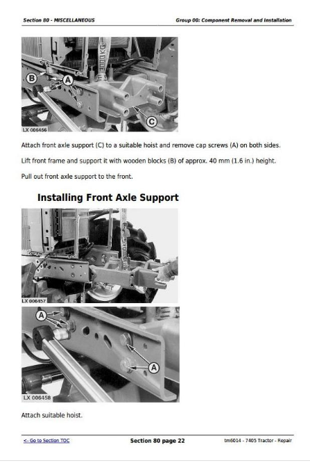
Removing Front Axle Support
Installing Front Axle Support
Group 05: Main Frame
Specifications
Removing and Installing Main Frame
Group 10: Front and Rear Wheels
Special or Essential Tools
Specifications
Removing a Wheel (Front or Rear)
Attaching Front Wheels
Attaching Rear Wheels
Attaching Rear Wheels (High Clearance)
Group 15: Front and Rear Wheels
Torques for Hardware - Swinging Drawbar
Section 90: Seat/Deluxe
Group 05: Deluxe Seat
Deluxe Seat
Safety Belt
Section 99: Special Tools
Group 05: Special Tools (Dealer-Fabricated)
DFRW29-Final Drive Housing Adapter
DFRW30-Axle Jacking Tool
DFRW79-Piston Holding Tool
Holding Device
Shifter Rail Detent Holding Tool
Socket Wrench Insert
John Deere 7405 Tractor Repair Service Manual (TM6014)
![]()