
John Deere Tractors 7430 Premium & 7530 Premium Repair Service Manual (TM8042)

Complete Repair Service Technical Manual for John Deere 2WD or MFWD European Tractors 7430 Premium & 7530 Premium, with all the technical information to maintain, repair, and service like professional mechanics.
John Deere 7430 & 7530 Premium (European Edition) Tractors workshop technical manual (repair) includes:
* Numbered table of contents easy to use so that you can find the information you need fast.
* Detailed sub-steps expand on repair procedure information
* Numbered instructions guide you through every repair procedure step by step.
* Notes, cautions and warnings throughout each chapter pinpoint critical information.
* Bold figure number help you quickly match illustrations with instructions.
* Detailed illustrations, drawings and photos guide you through every procedure.
* Enlarged inset helps you identify and examine parts in detail.
tm8042 - Premium Traktoren7430 & 7530 Reparatur (European Edition) Technical Manual.pdf
tm8042 - Premium Traktoren7430 & 7530 Reparatur (European Edition) Technical Manual.epub
Total Pages: 2,261 pages
File Format: PDF (bookmarked, ToC, Searchable, Printable, high quality)
Language: English
MAIN SECTIONS
Foreword
Safety
Safety Measures
General Information
Specifications
Tests and Adjustments
Predelivery Inspection
Engine
Removal and Installation of Components
Fuel, Air Intake, Cooling and Exhaust System
Removal and Installation of Components
Speed Control
Fuel System
Air Intake System
Cooling System
Cold-Weather Starting Aids
Exhaust System
Electrical System
Connector Information
Charging Circuit
Starting Circuit
Electrical Components
Electronic Control Units
Removal and Installation of Electronic Control Units
Removal and Installation of Terminating Resistors
AutoPowr/IVT Transmission
Removal and Installation of AutoPowr/IVT Transmission
Transmission Shift Units
Input Housing 2.0
Output Housing 2.0
Differential Drive Shaft Assembly
PowrQuad Transmission
Removal and Installation of Components
Transmission Shift Unit
PowrQuad Module
Range Transmission
Drive Train (without Transmission)
Removal and Installation of Components
U.J. Shaft and Torsion Damper
Front-Wheel Drive Clutch
Differential
Hydraulic Pump Drive
Final Drives
Rear PTO
Front Implement Drive
Steering and Brakes
Hydrostatic Steering
Brake Valve
Rear Brakes
Handbrake
Hydraulic Trailer Brake
Air-Brake System
AutoTrac
Hydraulic System
Operator Controls
Oil Filter, Charge Pump and Hydraulic Pump
Valves
Hitch
Selective Control Valves and Couplers
Independent Control Valves (ICVs)
Miscellaneous
Removal and Installation of Components
Main Frame
Front Wheels, Rear Wheels and Fenders
Trailer Mounting and Swinging Drawbar
Triple Link Suspension (TLS) of Front-Wheel Drive Axle
Triple Link Suspension (TLS) of Front-Wheel Drive Axle - 3D Animation
Hitch, Pick-Up
Operator`s Cab
Removal and Installation of Components
Controls and Instruments
Air Conditioning System
ClimaTrak
Heating System
Seats
Operator`s Cab
Cab Suspension
Special Tools
Special Tools (Dealer-Fabricated)
Special Tools (Available as Spare Parts)
tm8042 - Premium Traktoren7430â7530Reparatur -: (European Edition)
Table of Contents
Foreword
Section 05: Safety
Group 05: Safety Measures
Recognize Safety Information
”Important” Information
”Note” Information
Prevent Machine Runaway
Handle Fluids Safely—Avoid Fires
Prevent Battery Explosions
Prepare for Emergencies
Prevent Acid Burns
Avoid High-Pressure Fluids
Service Cooling System Safely
Remove Paint Before Welding or Heating
Avoid Heating Near Pressurized Fluid Lines
Work In Ventilated Area
Wear Protective Clothing
Practice Safe Maintenance
Park Machine Safely
Use Proper Lifting Equipment
Construct Dealer-Made Tools Safely
Support Machine Properly
Work in Clean Area
Illuminate Work Area Safely
Service Machines Safely
Use Proper Tools
Service Tires Safely
Service Front-Wheel Drive Tractor Safely
Safety Information - Air Brake System
Avoid Eye Contact With Radar
Keep ROPS Installed Properly
Replace Safety Signs
Dispose of Waste Properly
Live With Safety
Safety Measures on Electronic Control Units
Section 10: General Information
Group 05: Specifications
Specifications (Summary of References)
Engine Specifications
PTO Power Output
Cooling System
Electronic Fuel System with Common Rail (Denso)
Air Intake System
Electrical System
Hydrostatic Steering System
AutoTrac
Clutch
AutoPowr/IVT transmission
PowrQuad Plus transmission
AutoQuad Plus transmission
Creeper transmission
Rear PTO
Front PTO
Differential assembly
Differential lock
Final drives
Front-Wheel Drive
Front-Wheel Drive Axle with TLS
Cab Suspension:
Hydraulic Brakes
Handbrake
Parking Lock
Hydraulic System with Axial Piston Pump (PFC System)
Rockshaft
Front Hitch
Ground Speeds
Front and Rear Wheels
Dimensions and Weights
Capacities
Handling and Storing Diesel Fuel
Diesel Fuel
Bio-Diesel Fuel
Lubricity of Diesel Fuel
Diesel Engine Break-In Oil
Diesel Engine Oil
Transmission and Hydraulic Oil
Front-Wheel Drive Axle Oil
Heavy Duty Diesel Engine Coolant
Supplemental Coolant Additives
Grease
Oil Filters
Mixing of Lubricants
Lubricant Storage
Operating in Warm Temperature Climates
Alternative and Synthetic Lubricants
Unified Inch Bolt and Screw Torque Values
Metric Bolt and Screw Torque Values
Hydraulic system inch fitting torques
Hydraulic system metric fitting torques
Product Identification and Sub-Assembly Serial Numbers
Engine Serial Number
Transmission serial number
Front wheel drive axle serial number
Operator's cab serial number
Operator's seat serial number
Sub-assembly serial numbers
Group 10: Tests and Adjustments
Summary of References (Tune-Up)
Specifications
Using High-Pressure Washers
Preliminary Engine Test
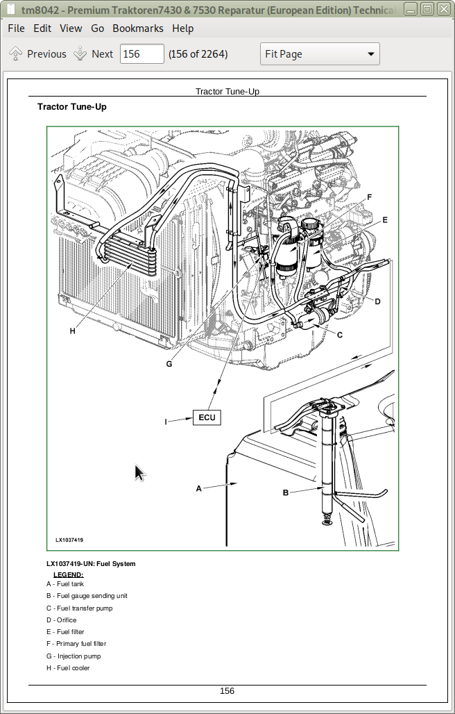
Tractor Tune-Up
Removing and Cleaning the Primary Air Cleaner Element
Checking the Air Cleaner Safety Element
Installing the Primary Air Cleaner Element
Checking Air Intake System Connections for Leaks
Checking Air Intake Hoses
Check the Crankcase Vent Hose for Clogging
Clean the Radiator Grille Screen
Adjust the Hood
Keep the Radiator Clean
Check Cap on Expansion Tank
Check the Radiator for Leaks
Check the Engine Thermostat
Checking the Fuel Transfer Pump Operation
Check the Fuel Filter
Bleed the Fuel System
Cleaning Water Trap
Run Engine until it is Warm and Check Engine Speeds
Clean the Battery, Cables and Battery Box with a Clean Cloth
Check Neutral Start Circuit
Check Operation of Starting Motor
Checking the Lighting Circuit
Final Engine Check
Tractor Operation Check
Group 15: Predelivery Inspection
Predelivery Inspection
Section 20: Engine
Group 00: Removal and Installation of Components
Engine - Removal and Installation of Components, Summary of References
Special Tools
Specifications
Remove the Engine
Install Engine
Engine Mounting
Replace the Engine Mountings
Section 30: Fuel, Air Intake, Cooling and Exhaust System
Group 00: Removal and Installation of Components
Fuel, Air Intake, Cooling and Exhaust Systems - Removal and Installation of Components, Summary of References
Remove Engine Hood
Install Engine Hood
Remove Battery
Install Battery
Group 05: Speed Control
Speed Control (Summary of References)
General Information
Replacing the Accelerator Pedal Assembly
Removing and Installing the Accelerator Pedal Potentiometer
Removing and Installing the Hand Throttle Potentiometer
Group 10: Fuel System
Fuel System (Summary of References)
General Information
Removing the Fuel Tank
Installing the Fuel Tank
Replacing the Fuel Gauge Sending Unit
Replacing the Fuel Transfer Pump
Changing the Fuel Filter
Bleeding Fuel System
Group 15: Air Intake System
Air Intake System - Summary of References
General Information
Air Cleaner - Exploded View
Replace the Sending Unit for Air Cleaner Restriction (B02)
Group 20: Cooling System
Cooling System (Summary of References)
General Information
Specifications
Remove and Install the Transmission Oil Cooler
Removing the Radiator
Change the Fan or the Viscous Fan Drive
Remove and Install the Charge Air Cooler
Removing and Installing the Expansion Tank
Installing the Radiator
Fill Cooling System with Coolant
Relieve Tension on the Drive Belt
Replace Drive Belt
Replace the Drive Belt Tensioner
Remove and Install the Alternator Drive Belt
Remove and Install Fan Console (with Mechanical Coolant Pump)
Group 25: Cold-Weather Starting Aids
Summary of References (Cold-Weather Starting Aids)
Fuel Preheater
Coolant Heater
Charge Pump and Transmission Preheater
Group 30: Exhaust System
Exhaust System (Summary of References)
General Information
Specifications
Exhaust System to Top Right
Section 40: Electrical System
Group 05: Connector Information
Connectors - Summary of References
Special Tools
General
Using high-pressure washers
Disconnecting electrical circuits
Strip Wire Ends
Install a Terminal
WEATHER PACK Connectors
METRI PACK Connectors with Terminal Lock at the Rear
METRI PACK Connectors with Terminal Lock at the Front
METRI PACK Connectors
Connectors for Electronic Control Units
Connectors
CRIMP SNAP IN Connectors
KOSTAL Connectors
DEUTSCH Connectors
Individual Terminals
Fuse and Relay Boxes
Group 10: Charging Circuit
Charging Circuit - Summary of References
Special Tools
Specifications
Repairing the Alternator
Disconnecting Electrical Circuits
Relieve Drive Belt Tension
Remove/Install the Alternator
Remove and Install the Pulley
Engine Wiring Harnesses
Group 15: Starting Circuit
Starter Motor Circuit - Summary of References
Specifications
Repairing the Starter Motor
Disconnecting Electrical Circuits
Remove and Install Starting Motor
Group 20: Electrical Components
Electrical Components – Summary of References
General information
Disconnecting electrical circuits
Adjusting the headlights
Adjust lights on the cab frame
Safety Instructions for Replacing a Halogen Bulb
Safety Instructions for Replacing Xenon (HID) Bulbs and Ballast Units
Replacing Xenon (HID) Worklights and Ballast Units
Section 45: Electronic Control Units
Group 05: Removal and Installation of Electronic Control Units
Electronic Control Units - Summary of References
Instructions when Replacing a Control Unit
Instructions when Replacing a VIN Control Unit
Safety Information
Repacing ATC Control Unit
Replacing BCU Control Unit
Replacing BIF Control Unit
Replacing DSM Control Unit
Replacing DTI Control Unit
Replacing ECU Control Unit
Replacing EPC Control Unit
Replacing ETC Control Unit
Replacing HTC Control Unit
Replacing JDL Control Unit
Replacing PLC/UIC Control Unit
Replacing SIC Control Unit
Replacing SSU Control Unit
Replacing TCU Control Unit
Replacing TEC Control Unit
Replacing TSC Control Unit
Replacing UIM Control Unit
Replacing VTI Control Unit
Replacing PC0 Power Module
Replacing PC5 Power Module
Replacing PC6 (HF) Power Module
Group 10: Removal and Installation of Terminating Resistors
Terminating Resistors - Summary of References
CAN BUS System - Vehicle
CAN BUS System - Power Train
ISOBUS
CAN BUS System - E-SCV/E-ICV
Section 53: AutoPowr/IVT Transmission
Group 00: Removal and Installation of AutoPowr/IVT Transmission
AutoPowr/IVT Transmission - Removal and Installation of Components, Summary of References
Special Tools
Specifications
Removal of AutoPowr/IVT Transmission
Installation of AutoPowr/IVT Transmission
Group 05: Transmission Shift Units
AutoPowr/IVT Transmission - Transmission Shift Controls, Summary of References
Special Tools - Summary of References
Recondition the Speed Control Lever
Recondition the Reverse Drive Lever
Recondition the Clutch Actuation Mechanism
Recondition the Manual Park Lock Release Mechanism
Manual Release of Park Lock
Group 10: Input Housing 2.0
AutoPowr/IVT Transmission - Input Housing, Summary of References
Important Information on Repair Level 2 of AutoPowr/IVT Transmission
Special Tools - Summary of References
Repair Specifications
Replace Hydrostatic Speed Sensor (B62)
Replace Pressure Switches (B87, S73, S74)
Replace Thermostat Valve
Replace Filter By-Pass Valve (Cold-Weather Starting)
Replace Oil Filter
Remove and Install Hydrostatic System Filter
Remove System Pressure Control Block
Install System Pressure Control Block
Remove Transmission Oil Pump
Recondition Transmission Oil Pump
Install Transmission Oil Pump
Remove Clutch Control Block
Recondition Clutch Control Block
Install Clutch Control Block
Separate the Input and Output Housings (Repair Level 2)
Join the Input and Output Housings (Repair Level 2)
Remove BG Disk Brake (Repair Level 2)
Install BG Disk Brake (Repair Level 2)
Remove Shift Turret (Repair Level 2)
Reconditioning the Shift Turret (Repair Level 2)
Install Shift Turret (Repair Level 2)
Remove Hydrostatic Unit (Repair Level 2)
Install Hydrostatic Unit (Repair Level 2)
Measure the Gaps Between Transmission Shafts (Repair Level 2)
Group 15: Output Housing 2.0
AutoPowr/IVT Transmission - Output Housing, Summary of References
Important Information on Repair Level 2 of AutoPowr/IVT Transmission
Special Tools - Summary of References
Specifications
Replace Transmission Input Speed Sensor (B61)
Replace Transmission Output Speed Sensor (B63)
Replace Park Lock Pressure Sensor (B90)
Remove Park Lock Control Block
Recondition Park Lock Control Block
Install Park Lock Control Block
Recondition Park Lock Cam
Replace Bleed Valve
Remove Pneumatic Pump
Install Pneumatic Pump
Remove the Idler Gear with Pneumatic Pump Drive (Repair Level 2)
Install the Idler Gear with Pneumatic Pump Drive (Repair Level 2)
Remove Idler Gear (Repair Level 2)
Install Idler Gear (Repair Level 2)
Remove the Direction Turret and Reverse Intermediate Shaft (Repair Level 2)
Disassembling the Direction Turret (Repair Level 2)
Assembling the Direction Turret (Repair Level 2)
Remove the Through-Drive Shaft (Repair Level 2)
Install the Through-Drive Shaft (Repair Level 2)
Install the Direction Turret and Reverse Intermediate Shaft (Repair Level 2)
Adjust the Installation Dimension of Reverse Intermediate Shaft (Repair Level 2)
Replace the Drive Shaft for the Hydrostatic Unit (Repair Level 2)
Group 20: Differential Drive Shaft Assembly
AutoPowr/IVT Transmission - Differential Drive Shaft, Summary of References
Special Tools - Summary of References
Specifications
Sectional View of Differential Drive Shaft
Remove the Differential Drive Shaft
Disassemble the Differential Drive Shaft
Differential Drive Shaft Cone Point Adjustment
Assembling the Differential Drive Shaft
Adjust the Installation Dimension of Differential Drive Shaft
Install the Differential Drive Shaft
Section 55: PowrQuad Transmission
Group 00: Removal and Installation of Components
PowrQuad Transmission - Removal and Installation of Components, Summary of References
Special Tools
Specifications
PowrQuad Plus Transmission, Removal and Installation
AutoQuad Plus Transmission, Removal and Installation
Remove the PowrQuad Transmission - Preliminary Work
Remove the PowrQuad Transmission
Install the PowrQuad Transmission
Remove the Range Transmission
Install the Range Transmission
Group 05: Transmission Shift Unit
PowrQuad Transmission - Transmission Shift Controls, Summary of References
PowrQuad Transmission - Check and Adjust the Shift Mechanism/Linkage and the Park Lock
PowrQuad Transmission - Remove the Shift Unit
PowrQuad Transmission - Recondition the Shift Unit
PowrQuad Transmission - Install the Shift Unit
PowrQuad Transmission - Recondition the Clutch Actuation Mechanism
Group 10: PowrQuad Module
PowrQuad Module, Summary of References
Special Tools, Summary of References
Repair Specifications
Transmission Sub-Assemblies
Replace the Temperature Sensor and Pressure Switches
Remove and Install the Oil Filter Housing
Replace the Oil Filter
Remove and Install the Front Valve Housing
Remove and Install Valves in the Front Valve Housing
Remove and Install the Front Transmission Cover
Remove and Install the Valves in the Front Transmission Cover
Remove and Install the Shift Valve Housing
Remove and Install the Valves in the Shift Valve Housing
Remove the Transmission Oil Pump
Recondition the Transmission Oil Pump
Install the Transmission Oil Pump
Remove the Gear-Shift Planetary Drive
Recondition the Gear-Shift Planetary Drive
Install the Gear-Shift Planetary Drive
Remove the B1 Brake Housing
Recondition the B1 Brake
Install the B1 Brake Housing
Remove the B2-B3 Brake Housing
Recondition the B2 Brake
Recondition the B3 Brake
Install the B2-B3 Brake Housing
Remove the C4 Clutch
Repairing the C4 Clutch
Install the C4 Clutch
Remove the Reverse Brake
Recondition the Reverse Brake
Install the Reverse Brake
Remove the Forward Clutch with Planetary Drive (Forward/Reverse)
Reconditioning Forward Clutch with Planetary Drive (Forward/Reverse)
Install the Forward Clutch with Planetary Drive (Forward/Reverse)
Replace the Clutch Carriers for the C4 Clutch and the Forward Clutch
Replace the Transmission Output Shaft and Rear PTO Drive Shaft
Group 15: Range Transmission
Range Transmission - Reconditioning, Summary of References
Special Tools, Summary of References
Specifications
Range Transmission - Sectional View
Remove the Park Lock Pawl, Shift Components and Differential Drive Shaft
Remove the Drive Shaft
Disassemble the Drive Shaft
Assemble the Drive Shaft
Install the Drive Shaft
Adjust End Play of Drive Shaft
Install Differential Drive Shaft and Adjust Cone Point
Adjust End Play of Differential Drive Shaft
Install the Park Lock Pawl and Shift Components
Adjust the Range Shift Mechanism
Recondition the Shift Cover
Replace the Sensors B35 and B172
Section 56: Drive Train (without Transmission)
Group 00: Removal and Installation of Components
Drive Systems - Removal and Installation of Components, Summary of References
Special Tools
Specifications
Removing the FWD Clutch
Installing the FWD Clutch
Remove Differential Housing
Install Differential Housing
Remove the Final Drives
Install the Final Drives
Remove Rear PTO
Install Rear PTO
Removing the Front PTO
Installing the Front PTO
Group 05: U.J. Shaft and Torsion Damper
U-Jointed Shafts and Torsion Damper - Summary of References
Special Tools
Use of Special Tool KJD10426
Specifications
Remove Front-Wheel Drive U.j. Shaft
Recondition the U.j. Shaft
Install Front-Wheel Drive U.j. Shaft
Remove U.j. Shaft (Engine)
Remove the Torsion Damper
Changing the Torsion Damper Bearings
Install the Torsion Damper
Install Engine U.J. Shaft
Group 10: Front-Wheel Drive Clutch
Drive Systems - Front-Wheel Drive Clutch, Summary of References
Special Tools
Front-Wheel Drive Clutch - Specifications
Front-Wheel Drive Clutch - Replace Front-Wheel Drive Axle Speed Sensor (B89)
Front-Wheel Drive Clutch - Replace Solenoid Valve (Y03)
Front-Wheel Drive Clutch - Sectional View
Front-Wheel Drive Clutch - Exploded View
Disassemble the Front-Wheel Drive Clutch
Recondition Front-Wheel Drive Clutch
Assemble the Front-Wheel Drive Clutch
Front-Wheel Drive Clutch - Adjust Axial Play of Clutch Shaft
Group 15: Differential
Drive Systems - Differential, Summary of References
Special Tools
Differential - Specifications
General Repair Procedures
Replace Solenoid Valve for Differential Lock (Y05)
Differential - Sectional View
Differential - Exploded View
Remove the Differential
Recondition the Differential
Install the Differential
Differential - Adjust Preload
Differential - Adjust Backlash
Group 20: Hydraulic Pump Drive
Drive Systems - Hydraulic Pump Drive, Summary of References
Special Tools
Repair Specifications
Hydraulic Pump Drive - Sectional View
Remove and Disassemble Pump Drive Pinion Gear
Remove and Disassemble Pump Drive Gear
Assemble and Install Pump Drive Gear
Assemble and Install Pump Drive Pinion
Check and Adjust the Backlash of the Pump Drive Pinion
Group 25: Final Drives
Drive Systems - Final Drives, Summary of References
Final Drives - Special Tools
Final Drives - Specifications
Final Drives - Sectional View
Removing the Planetary Carrier
Disassemble Planetary Carrier
Assemble Planetary Carrier
Remove Axle Housing
Disassemble and Asssemble Axle Housing
Disassemble and Assemble Axle Shaft
Final Drives - Install Axle Housing
Final Drives - Installing the Planetary Carrier and Checking the Rolling Drag Torque
Group 30: Rear PTO
Drive Systems - Rear PTO, Summary of References
Rear PTO - Special Tools
Rear PTO - Specifications
Replace the Output Shaft Seal Ring
PTO Clutch - Cross-Sectional View
PTO Clutch - Exploded View
Remove the PTO Clutch
Recondition the PTO Clutch
Recondition the PTO Brake
Install the PTO Clutch
PTO Drive Train - Sectional View
PTO Drive Train - Exploded View
Remove the PTO Drive Train
Recondition the Output Shaft
Recondition the Countershaft
Recondition the PTO Shifter
Install the PTO Drive Train
Adjust Taper Roller Bearing of Countershaft
Adjust the Tapered Roller Bearing of the Bearing Support
Recondition Y81 - Proportional Solenoid Valve for Rear PTO
Replace B06 - Rear PTO Speed Sensor
Rear PTO - Recondition the Oil Sight-Glass
Group 40: Front Implement Drive
Front Implement Drive – Summary of References
General Information
Specifications
Summary of Torques
Preliminary Work
Install and Remove Drive Shaft
Section 60: Steering and Brakes
Group 05: Hydrostatic Steering
Steering and Brakes - Hydrostatic Steering, Summary of References
Special Tools
Specifications
Preliminary Work
Disconnect/Connect Steering or Brake Hoses
Exploded View of Steering Unit
Steering Unit - Removal
Steering Unit Installation
Group 15: Brake Valve
Steering and Brakes - Brake Valve, Summary of References
Brake Valve - Special Tools
Brake Valve - Repair Specifications
Accumulators - Remove and Install
Recondition Guide Piece and Piston
Brake Valve - Exploded View
Remove Brake Valve (Power Fill Brakes)
Recondition Brake Valve (Power Fill Brakes)
Install Brake Valve (Power Fill Brakes)
Remove Power-Fill Brake Valve with MFWD and Disk Brake
Recondition Power-Fill Brake Valve with MFWD and Disk Brake
Install Power-Fill Brake Valve with MFWD and Disk Brake
Group 20: Rear Brakes
Steering and Brakes - Rear Wheel Brakes, Summary of References
Rear Brakes - Repair Specifications
Rear Wheel Brakes - Exploded View
Remove the Rear Brakes
Recondition the Rear Brakes
Install the Rear Brakes
Replace Retraction Pins on the Rear Wheel Brakes
Group 25: Handbrake
Steering and Brakes - Handbrake, Summary of References
Handbrake - Specifications
Handbrake - Exploded View
Remove Handbrake
Install Handbrake
Handbrake - Adjust the Brake Band
Handbrake components
Handbrake - Replace Handbrake Cable
Group 30: Hydraulic Trailer Brake
Steering and Brakes - Hydraulic Trailer Brake, Summary of References
Hydraulic Trailer Brake - Repair Specifications
Repair Information
Hydraulic Trailer Brake - Change Trailer Brake Valve
Group 35: Air-Brake System
Steering and Brakes - Air Brake System, Summary of References
Special Tools
Repair Specifications
Safety Instructions
Screw Union Installation
Change the Compressor
Gaskets for the Compressor
Change the Compressed Air Tank
Change the Pressure Control Valve
Change the Precharge Valve
Changing the Delay Valve
Change the Trailer Control Valve (for Dual-Line Brakes)
Change the Trailer Control Valve (for Single-Line Brakes)
Changing the Coupling Ends
Group 40: AutoTrac
Steering and Brakes - AutoTrac, Summary of References
Specifications
Remove and Install Steering Control Valve (Y49)
Remove and Install Steering Wheel Position Sensor (B138)
Section 70: Hydraulic System
Group 05: Operator Controls
Recondition Controls - Summary of References
Specifications
Selective Control Valves (M-SCVs) - Remove and Install the Actuating Elements
Selective Control Valves (M-SCV) - Adjust the Bowden Cable
Remove and Install the Multifunction Lever (on Shift Console) for M-SCVs
Adjust the Multifunction Lever (on Shift Console) for M-SCVs
Remove and Install the Multifunction Lever (on Shift Console) for M-ICVs
Adjust the Multifunction Lever (on Shift Console) for M-ICVs
Group 10: Oil Filter, Charge Pump and Hydraulic Pump
Oil Filter, Charge Pump and Hydraulic Pump - Summary of References
Other Material
Specifications
Remove and Install the Hydraulic Oil Primary Filter
Repair Hydraulic oil filter
Remove and Install the Charge Pump
Charge Pump - Checking the Lube Oil Valve
Remove and Install the Additional Oil Reservoir
Hydraulic Oil Reservoir — Restrictor
Hydraulic Pump - Removing and Installing the Pressure-and-Flow Controller
Hydraulic Pump - Reconditioning the Pressure-and-Flow Controller
Remove and Install the Hydraulic Pump
Repair Hydraulic Pump
Group 15: Valves
Recondition the Valves - Summary of References
Recondition the Valves - Special Tools, Summary of References
Repair Specifications
Hydraulic System — General Instructions on Safety and Repair
Removal and Installation of the Priority 1 Control Block
Reconditioning the Priority 1 Control Block
Removal and Installation of the Control Block with/without Priority 2
Reconditioning the Priority 2 Control Block
Reconditioning the Control Block (without Priority 2)
Removal and Installation of the Priority 3 Control Block
Reconditioning the Priority 3 Control Block
Group 20: Hitch
Reconditioning the Hitch - Summary of References
Recondition the Hitch - Special Tools, Summary of References
Other Material
Repair Specifications
Rockshaft Valve, Removing and Installing the Stepper Motor
Removal and Installation of the Hitch Valve
Reconditioning the Hitch Valve
Rockshaft - Remove and Install the Position Sensor and Toothed Segment
Hitch - Remove and Install Rockshaft
Rockshaft - Remove Rockshaft Cylinders
Hitch — Repairing the lift cylinder
Rockshaft - Install Rockshaft Cylinders
Hitch - Remove and Install Draft Load Potentiometer and Draft Link Support
Hydraulic Draft Link Stabilizer Bars (HSB) - Remove and Install the Control Block
Hydraulic Draft Link Stabilizer Bars (HSB) - Recondition the Control Block
Hydraulic Draft Link Stabilizer Bars (HSB) - Remove and Install
Recondition the Hydraulic Draft Link Stabilizer Bars (HSB)
Remove and Install the Hydraulic Center Link (HCL)
Recondition the Hydraulic Center Link (HCL)
Group 25: Selective Control Valves and Couplers
Reconditioning the Selective Control Valves (SCVs) and Couplers - Summary of References
Repair Specifications
Repair the Selective Control Valves (SCVs) and Couplers - General Instructions on Safety and Reconditioning
Selective Control Valves (E-SCVs) - Remove and Install the Stepper Motors
Removal and Installation of the Selective Control Valves (SCVs)
Reconditioning the Selective Control Valves (M-SCVs 100) (up to Tractor Serial Number 663408)
Reconditioning the Selective Control Valves (M-SCVs 100) (from Tractor Serial Number 663409)
Reconditioning the Selective Control Valves (M-SCVs 200) (up to Tractor Serial Number 663408)
Reconditioning the Selective Control Valves (M-SCVs 200) (from Tractor Serial Number 663409)
Reconditioning the Selective Control Valves (M-SCVs 300) (up to Tractor Serial Number 663408)
Reconditioning the Selective Control Valves (M-SCVs 300) (from Tractor Serial Number 663409)
Reconditioning the Selective Control Valves (M-SCVs 350) (up to Tractor Serial Number 663408)
Reconditioning the Selective Control Valves (M-SCVs 350) (from Tractor Serial Number 663409)
Reconditioning the Selective Control Valves (E-SCVs) (up to Tractor Serial Number 663408)
Reconditioning the Selective Control Valves (E-SCVs) (from Tractor Serial Number 663409)
Reconditioning the Selective Control Valves (E-SCVs 350) (up to Tractor Serial Number 663408)
Reconditioning the Selective Control Valves (E-SCVs 350) (from Tractor Serial Number 663409)
Selective Control Valves (SCVs) - Reconditioning the Couplers
Group 30: Independent Control Valves (ICVs)
Independent Control Valves (ICV) - Summary of References
Specifications
Removing the Independent Control Valves (M-ICVs)
Reconditioning the Independent Selective Control Valves (M-ICVs) (up to Tractor Serial Number 663408)
Reconditioning the Independent Selective Control Valves (M-ICVs) (from Tractor Serial Number 663409)
Install the Independent Control Valves (M-ICVs)
Independent Selective Control Valves (E-ICVs) - Remove and Install the Stepper Motors
Removing the Independent Control Valves (E-ICVs)
Reconditioning the Independent Selective Control Valves (E-ICVs) (up to Tractor Serial Number 663408)
Reconditioning the Independent Selective Control Valves (E-ICVs) (from Tractor Serial Number 663409)
Install Independent Control Valves (E-ICVs)
Section 80: Miscellaneous
Group 00: Removal and Installation of Components
Miscellaneous - Removal and Installation of Components, Summary of References
Special Tools
Specifications
Remove and Install the Main Frame (Summary of References)
Preliminary Work for Removal of the Main Frame
Remove the Main Frame
Install Main Frame
Remove and Install the Front-Wheel Drive Axle (Summary of References)
Remove the Front-Wheel Drive Axle
Install the Front-Wheel Drive Axle
Remove the Front-Wheel Drive Axle with TLS
Install the Front-Wheel Drive Axle with TLS
Remove and Install the Front Axle Support (Summary of References)
Remove the Front Axle Support
Install the Front Axle Support
Group 05: Main Frame
Miscellaneous - Main Frame, Summary of References
Repair specifications
Recondition the Main Frame
Group 10: Front Wheels, Rear Wheels and Fenders
Front Wheels, Rear Wheels and Fenders – Summary of References
Special Tools
Specifications
Pivoting Front Fender
Remove Front and Rear Wheels
Reconditioning the Front and Rear Wheels
Install Front and Rear Wheels
Group 15: Trailer Mounting and Swinging Drawbar
Trailer Mounting and Swinging Drawbar - Summary of References
Specifications
Check the Manually-Operated Trailer Hitch for Wear
Check the Manually-Operated Hitch for Wear (Italy and Spain Only)
Check the Remote-Controlled Trailer Hitch for Wear
Trailer Hitch, Check the Guide Rails
Checking the Tow-Hook for Wear
Checking the Hitch Ball for Wear
Check the Drawbar for Wear
Install Rigid Trailer Mounting
Install the Guide Rails
Repair of Automatic Trailer Hitch
Remote Control for Automatic Trailer Hitch
Reconditioning the height-adjustable trailer hitch (Italy and Spain only)
Swinging Drawbar
Swinging Drawbar with Pick-Up Hitch
Adjust the Retaining Strap
Group 20: Triple Link Suspension (TLS) of Front-Wheel Drive Axle
Triple Link Suspension (TLS) of Front-Wheel Drive Axle - Summary of References
Special Tools
Specifications
Relieve Pressure in the Hydraulic System
Remove and Install the Oscillation Limiter
Remove the Panhard Link
Install the Panhard Link
Remove and Install the Sensor Rod
Remove the Sensor for TLS Position
Repairing the Sensor for TLS position
Install the Sensor for TLS Position
Remove the Hydraulic Cylinder
Recondition the Hydraulic Cylinder
Install the Hydraulic Cylinder
Remove the Control Valve Block
Recondition the Valves in the Control Valve Block
Install the Control Block
Remove the Accumulator
Recondition the Accumulator
Install the Accumulator
Remove and Recondition the Bearing Support
Install the Bearing Support
Group 203D: Triple Link Suspension (TLS) of Front-Wheel Drive Axle - 3D Animation
Triple Link Suspension (TLS) of Front-Wheel Drive Axle - 3D Animation - Summary of References
Remove and Install the Oscillation Limiter - 3D Animation
Remove the Panhard Link - 3D Animation
Install the Panhard Link - 3D Animation
Remove and Install the Connecting Rod - 3D Animation
Remove the Sensor for TLS Position - 3D Animation
Recondition the Sensor for TLS Position - 3D Animation
Install the Sensor for TLS Position - 3D Animation
Remove the Hydraulic Cylinder - 3D Animation
Remove the Control Block - 3D Animation
Recondition the Valves in the Control Block - 3D Animation
Install the Control Block - 3D Animation
Remove the Accumulator - 3D Animation
Recondition the Accumulator - 3D Animation
Install the Accumulator - 3D Animation
Remove and Recondition the Bearing Support - 3D Animation
Install the Bearing Support - 3D Animation
Group 25: Hitch, Pick-Up
Pick-Up Hitch - Summary of References
Specifications
Pick-Up Hitch — General Safety and Repair Information
Check Tow Hook on Pick-Up Hitch for Wear
Remove and Install Pick-Up Hitch
Pick-Up Hitch - Exploded View
Pick-Up Hitch - Control Lever and Lift Links
Pick-Up Hitch - Hydraulic Parts
Electro-Hydraulically-Controlled Pick-Up Hitch - Electro-Hydraulic Parts
Repairing the Retainer Spring
Repairing the Latch Housing
Recondition the Hydraulic Cylinder
Adjust the Lift Links
Adjust the Guide Stop
Adjusting the Locking Pin
Pick-Up Hitch — Operational Check
Section 90: Operator's Cab
Group 00: Removal and Installation of Components
Operator's Cab - Removal and Installation of Components, Summary of References
Special Tools
Specifications
Tilt Operator's Cab Upward
Tilt the Operator's Cab Downward
Remove Operator's Cab
Install Operator's Cab
Check and Adjust Shift Mechanisms/Linkages
Group 05: Controls and Instruments
Controls and Instruments - Summary of References
Remove and Install the Dome Light
Remove and Install the Console Light
Group 10: Air Conditioning System
Air-Conditioning System (Summary of References)
Air-Conditioning System - Special Tools, Summary of References
Repair Specifications
Torques for Tightening Refrigerant Hoses
Air-Conditioning System - Safety at Work
Storage of Refrigerant Containers
Air-Condtioning/ClimaTrak - Important
Air-Conditioning System - Service Work
Air-Conditioning System - Preventive Maintenance
Air-Conditioning - Test with Air-Conditioning Service Unit
Discharge the System
Evacuate the System
Fill with Refrigerant Oil
Air-Conditioning Service Unit - Fill with Refrigerant Oil
Instructions for Starting Up the DENSO Air-Conditioning Compressor
Fill the System
Leak Test
Remove the Compressor
Checking Level in the Compressor
Disassemble the Compressor Clutch
Check Clutch Hub Clearance
Check Compressor Manifold
Install Compressor
Remove and Install Condenser
Remove and Install Receiver-Drier
Removing and Installing the Evaporator and Expansion Valve
Replacing the Expansion Valve
Install the Condensation Water Drain Hoses
B130 - Sensor for Refrigerant Pressure; Removal and Installation
ETC Control Unit; Removal and Installation
Group 15: ClimaTrak
ClimaTrak - Summary of References
Remove and Install the ATC Controller (ClimaTrak)
Remove and Install Sensor for Ambient Temperature (at Front) (B125)
Remove and Install Sensor for Ambient Temperature (at Rear) (B126)
Remove and Install Sensor for Inside Temperature (B127)
Remove and Install Sensor for Outlet Temperature (B128)
Remove and Install Sensor for Evaporator Core Temperature (B129)
B130 - Sensor for Refrigerant Pressure; Removal and Installation
Remove and Install the Heater Valve (B131)
Remove and Install Adjusting Motor for Air Distribution (B132)
Remove and Install the Defog Sensor (B143)
Group 20: Heating System
Heating System (Summary of References)
Remove and Install the Fan and Radiator
Water Valve (B131) Removal and Installation
Mode Control for Position of Air Distribution Flaps (B132), Removal and Installation
Remove and Install the Cab Air Filter
Remove and Install the Recirculated Air Filter
Group 25: Seats
Seats (Summary of References)
Specifications
Seats - Special Tools, Summary of References
Comfort Seat MSG85 - Remove and Install Lumbar Support
Comfort Seat MSG85 - Remove and Install the Lap-Strap
Comfort Seat MSG85 - Remove and Install the Backrest
Comfort Seat MSG85 - Remove and Install the Adjusting Mechanism for Seat Tilt and Seat Length
Comfort Seat MSG85 - Remove and Install the Integral Turntable and Baseplate
Comfort Seat MSG85 - Remove and Install the Horizontal Shock Absorber
Comfort Seat MSG85 - Remove and Install the Horizontal Spring Assembly
Comfort Seat MSG85 - Remove and Install the Upper Section of Spring Assembly
Comfort Seat MSG85 - Remove and Install the Vertical Shock Absorber
Comfort Seat MSG85 - Remove and Install the Lower Section of Spring Assembly
Comfort Seat MSG85 - Remove and Install the Weight-Adjusting Mechanism
Comfort Seat MSG85, Remove and Install the Rocker
Comfort Seat MSG85 - Remove and Install the Pneumatic Lumbar Support
Comfort Seat MSG85 - Remove and Install the Seat Switch
Air Comfort Seat MSG95 - Remove and Install the Compressor
Air Comfort Seat MSG95 - Remove and Install the Air Spring
Air Comfort Seat MSG95, Check and Adjust the Height-Adjustment Bowden Cables and Lever
Air Comfort Seat MSG95, Remove and Install the Height-Adjustment Bowden Cables and Lever
Air Comfort Seat MSG95 - Adjust the Level Control (Micro-Switch, Vent Valve)
Air Comfort Seat MSG95 - Remove and Install the Level Control with Height Stop
Air Comfort Seat MSG95 - Remove and Install the Compressed-Air Hoses (Hoses with Quick-Coupling System)
Air Comfort Seat MSG95 - Remove and Install the Compressed-Air Hoses (Hose System with Clamps)
Air Comfort Seat MSG95 - Remove and Install the Air Tank with Additional Capacity
Recondition the CommandArm
Exploded View of the Instructional Seat
Group 30: Operator's Cab
Operator's Cab (Summary of References)
Remove and Install the Cab Frame
Cab Mounting Torques
Remove and Install Inner Roof Trim
Remove and Install the Panoramic Windshield
Remove and Install the Rear Window
Remove and Install the Outer Roof
Remove and Install the Roof Hatch
Adjust the Door Lock
Adjust Windshield and Rear Window Contact Pressure
Remove and Install the Cab Door
Remove and Install the Panorama Door
Remove and Install the Roller Sun-Visors
Remove and Install the Side Panel
Group 35: Cab Suspension
Cab Suspension - Summary of References
Important Instructions
Specifications
Relieve Pressure in the Hydraulic System
Install and Remove the Cab Suspension Shields
Remove and Install the Sensor Rod
Adjust the Sensor Rod
Remove and Install the Position Sensor
Remove the Accumulator
Recondition the Accumulator
Install the Accumulator
Remove the Hydraulic Cylinder
Install the Hydraulic Cylinder
Remove and Install the Panhard Link
Bleed Air from the Cab Suspension Hydraulic Cylinders
Section 99: Special Tools
Group 05: Special Tools (Dealer-Fabricated)
DFLX1 - Adapter Strut
DFLX4 - Suspension Device for AutoPowr/IVT Transmission
DFLX5 - Lifting Eye for Operator's Cab
DFLX6 - Bushing
DFLX7 - Turning Device
DFLX10 - Holding Tool
DFLX13 - Holding Device
DFLX14 – Suspended MFWD Axle Housing Bracket
DFLX17 - Assembly and Guide Mandrels
DFLX20 - Unlocking Device for Park Lock
DFLX21 - Special Wrench
DFLX22 – Socket Wrench Insert
DFLX23 – Socket Wrench Insert
DFLX24 - Seal Installer
DFLX25 – Driver
DFLX27 – Driver
DFLX28 - Installation Tool for Park Lock Control Block
DFLX29 - Support
DFLX30 - Tube for Park Lock Control Block, Removal and Installation
DFLX31 - Bushing
DFLX41 – Socket Wrench Insert
DFLX42 - Turning Device
DFLX43 - Mandrel
DFRW29 - Housing Adapter
DFRW30 - Axle Jacking Tool
DFRW79 – Piston Holding Tool
Group 10: Special Tools (Available as Spare Parts)
D01019AA - Single-Stage, Manually Operated Pump
D01042AA – Load-Positioning Sling
D01045AA - Bushing, Bearing and Seal Driver Set
D01047AA - Set of Pullers for Removing Bearings and Bushings
D01210AA - Slide Hammer Puller
D05007ST - Tractor Splitting Stand
FKM10427 - Crimping Pliers
FKM10455 - Extraction Tool
FKM10456 - Extraction Tool
FKM10457 - Extraction Tool
FKM10461 - Wiring Harness Repair Kit
FKM10464 - Single-Acting Hydraulic Ram
FKM10469 - Crimping Pliers
FKM10474 - Fill-and-Check Device
JDG18 - Snap Ring Tool
JDG19 – Special Mounting Brackets
JDG23 – Lifting Sling
JDG236 - Installer
JDG359 - Electrical Repair Tool Kit
JDG360 - DEUTSCH Crimping Pliers
JDG361 - Extraction Tool
JDG362 - Extraction Tool
JDG364 - Extraction Tool
JDG536 - Handle
JDG708 - AMP Crimping Tool
JDG731 - Special Socket Wrench Insert
JDG753 - Driver Disk
JDG754 - Spring Compressor
JDG755 - Installer
JDG765 - Bushing Installer
JDG772 - Planetary Installation Tool
JDG775 - Seal Installer
JDG776 - Extraction Tool
JDG777 - Extraction Tool
JDG778A – Adjusting Tool
JDG781 - Bearing Installer Tool Set
JDG783 - Crimping Pliers
JDG785 - Extraction Tool
JDG811 - Puller
JDG820 – Flywheel Turning Tool
JDG869 - Backlash Adjusting Tool
JDG1182 - Adapter
JDG1369 - Terminal Extraction Tool
JDG1655A - Suspension Device for PowrQuad Transmission
JDG1725 - Extraction Tool
JDG1727 - Crimping Pliers
JDG1744 - Electrical Repair Tool Kit
JDG10974EU - Air-Conditioning Service Unit
JDT44 - Socket Wrench (2-1/2 in.)
JT01673 - Installer
JT01778 - Removal Tool
JT02043 - Support Stand
JT02044 - Support Stand
JT05723 – Medium-Duty Rear Tractor Splitting Stand
JT05724 – Medium-Duty Front Tractor Splitting Stand
JT05725 – Universal Support Stand
JT05726 – Universal Support Stand
JT07131 - Removal Tool
JT07211 - Support Stand
KJD10168A - Ring Nut Socket
KJD10169B - Special Puller
KJD10171 - Driver
KJD10173 - Special Tool
KJD10178D - Cab Tilting Device
KJD10227 - Special Tool
KJD10235 - Seal Installer
KJD10278 - Special Tool
KJD10283 - Supplementary Kit
KJD10293 – Disconnecting Tool
KJD10426 - Special Tool
KJD10443 - Charging Valve
FKM10436 - Refrigerant Oil Injector
KJD10444 - Leak Tester
KJD10436 - Oil Injector
KJD10501 - Disconnecting Tools (Kit)
KJD10527 - Extraction Tool
KJD10528 - Measurement Unit
KJD10529 - Cutting Tool
KJD10530 - Pliers
KJD10539 - Adapter for Support Stand JT07211
KJD10540 - Special wrench
KJD10547 - Special Socket Wrench Insert
KJD10564 - Special Socket Wrench Insert
KJD10570 - Safety Equipment (Air-Conditioning Service)
KJD10571 - Protective Cover for Air-Conditioning Service Unit
KJD10572 - Standard Flushing Kit (Air-Conditioning Service)
KJD10573 - UV Contrast Agent (Air-Conditioning Service)
KJD10574 - Hose Extensions (2.5 m) (Air-Conditioning Service)
KJD10575 - PAG Oil (Air-Conditioning Service)
KJD10576UV - Lamp and Safety Goggles (Air-Conditioning Service)
KJD10577 - Filter/Receiver-Drier Cartridge for Air-Conditioning Service Unit
KJD10581 - Trolley for Wheel Removal and Installation
KJD10587 - Torque screwdriver, 1 to 5 N•m
KJD10630 - Installation Aid
KJD10631 - Installation Aid
KJD10632 - Installation Aid
KLM10019-1 - Crimping Pliers
KLM10019-4 - Extraction Tool
FKM10440 - Vacuum Pump
FKM10442 - Discharging Unit
FKM10445 - Universal pressure test kit
FKM10446 - PAG Refrigerant Oil (ND-Oil8; 250 ml)
FKM10447 - Refrigerant container (R134a; 920g; 750 ml)
FKM10478 - Service Unit
OTC7062A - Holder
D01003AA - Repair Stand with Swivel Mechanism
KJD10235 - Seal Installer
KJD10240 - Bearing Puller Attachment
KJD10242 - Lifting Bail
KJD10477 - Bearing Puller
KJD10593 - Adjusting Screws
KJD10594 - M12 Eyebolt
KJD10595 - M18 Eyebolt
KJD10598 - Internal Puller
KJD10599 - Bearing Puller Attachment
KJD10600 - Lifting Bail
KJD10601 - Internal Puller
KJD10602 - Support
KJD10603 - Eyebolt Set
KJD10605 - Driver
KJD10606 - Handle
KJD10607 - Measuring Strap
KJD10608 - Measuring Block
KJD10609 - Installation Tool
KJD10610 - Driver
KJD10611 - Adjusting Screws
KJD10613 - Forcing Sleeve
KJD10615 - Guide Pin
KJD10616 - Installation Tool
KJD10617 - Installation Tool
KJD10618 - Driver
KJD10621 - Thrust Piece
KJD10622 - Basic Bearing Puller
KJD10623 - Bearing Puller Attachment
KJD10625 - Thrust Piece
KJD10624 - Bearing Puller Attachment
KJD10626 - Transmission Support
KJD10633 - Basic Bearing Puller
KJD10634 - Pliers
KJD10709 – Lifting Tool for Planetary Drive
John Deere Tractors 7430 Premium & 7530 Premium Repair Service Manual (TM8042)
![]()