
John Deere Tractors 7600, 7700, 7800 Diagnosis and Tests Service Technical Manual (TM1501)
Complete Diagnosctics & Tests Technical Manual with electrical wiring diagrams for John Deere 7600, 7700 and 7800 (2WD or MFWD) Tractors, with all the technical information to maintain, diagnose and service like professional mechanics.
John Deere 2WD or MFWD Tractors 7600, 7700 and 7800 workshop Diagnosis & Tests technical manual includes:
* Numbered table of contents easy to use so that you can find the information you need fast.
* Detailed sub-steps expand on repair procedure information
* Numbered instructions guide you through every repair procedure step by step.
* Troubleshooting and electrical service procedures are combined with detailed wiring diagrams for ease of use.
* Notes, cautions and warnings throughout each chapter pinpoint critical information.
* Bold figure number help you quickly match illustrations with instructions.
* Detailed illustrations, drawings and photos guide you through every procedure.
* Enlarged inset helps you identify and examine parts in detail.
tm1501 - 7600, 7700 and 7800 Tractors Technical Manual - Operation and Test.pdf
Total Pages: 1,561 pages
File Format: PDF (bookmarked, ToC, Searchable, Printable)
Language: English
MAIN SECTIONS
Foreword
Safety Information
Safety
General Information
Operational Checks
General Reference Information
Test Equipment Calibration
Diagnostic Service Codes
CCU
HCU
LHP
PCU
Observable Symptoms
Brakes
Hitch
Operators Station
Hydraulics
Engine Operation and Tests
General Information
Fuel, Air Intake and Engine Cooling Systems
Fuel/Air/Cooling System Theory of Operation
Electrical Operation and Tests
Diagnostic Codes and Addresses
Electrical System Information
System Diagrams
Sub-System Diagnostics
Calibration and References
Power Shift Transmission
Operational Checks
Power Shift Transmission Diagnosis
Theory of Operation
PowrQuad PowrQuad is a trademark of Deere & Company.
Transmission
PowrQuad PowrQuad is a trademark of Deere & Company.
Transmission Operational Checks
PowrQuad PowrQuad is a trademark of Deere & Company.
Transmission Diagnosis
Theory of Operation
Drive Systems
Operational Checks
Drive System Diagnosis
Adjustments
Theory of Operation
Steering and Brakes
Tests and Adjustments
Theory of Operation
Hydraulic System
Operational Checks
Hydraulic System Diagnosis
Calibration and Adjustments
Theory of Operation
Operator Station
Air Conditioning Operational Checks
Air Conditioning System Diagnosis
Air Conditioning Theory of Operation
Dealer Fabricated Tools
tm1501 - 7600, 7700 and 7800 Tractors Operation and Test
Table of Contents
Foreword
Section 205: Safety Information
Group 05: Safety
Recognize Safety Information
Handle Fluids Safely—Avoid Fires
Prevent Battery Explosions
Prepare for Emergencies
Prevent Acid Burns
Handle Chemical Products Safely
Avoid High-Pressure Fluids
Park Machine Safely
Support Machine Properly
Wear Protective Clothing
Work in Clean Area
Service Machines Safely
Work In Ventilated Area
Illuminate Work Area Safely
Replace Safety Signs
Use Proper Lifting Equipment
Avoid High-Pressure Fluids
Service Accumulator Systems Safely
Remove Paint Before Welding or Heating
Avoid Heating Near Pressurized Fluid Lines
Keep ROPS Installed Properly
Service Tires Safely
Avoid Harmful Asbestos Dust
Practice Safe Maintenance
Use Proper Tools
Dispose of Waste Properly
Prevent Machine Runaway
Handle Starting Fluid Safely
Service Cooling System Safely
Stay Clear of Rotating Drivelines
Protect Against High Pressure Spray
Construct Dealer-Made Tools Safely
Clean Vehicle of Hazardous Pesticides
Live With Safety
Section 210: General Information
Group 05: Operational Checks
Electrical System Checks
Before You Start
Transmission Checks
Before You Start
Hydraulic System Checks
Air Conditioning System Checks
Group 10: General Reference Information
JT03412—Supplemental Pressure Test Kit
JT03413—Supplemental Flow Test Kit
JT03419—ORFS Fitting Kit
JT05406—Master Hydraulic Flow Test Fitting Kit
JT05416—Consumer Products Hydraulic Flow Test Kit
JT05452—Power Shift Transmission Test Kit
JT03134—Power Shift Transmission Optional Accessories
JT05469—Flowmeter Kit
JT05470—Agricultural Universal Pressure Test Kit
Required Test Fittings
List of Diagnostic Adapters—ORFS
Unified Inch Bolt and Screw Torque Values
Metric Bolt and Screw Torque Values
JIC Hydraulic Symbols
Glossary of Terms
Group 15: Test Equipment Calibration
JDG282 Temperature Gauge Check
Calibration Check of OTC Flow Meters
Method No. 1: Flow Meter (Main Pump Quick Check From SCV)
Method No. 2: Volume Check From Flow Meter
Pressure Gauge Calibration Checker
Section 211: Diagnostic Service Codes
Group 05: CCU
CCU 001 - Fuel Level Sensor Circuit, Repair
CCU 003 - Fuel Level Low
CCU 010 - Engine Coolant Temperature High, Repair
CCU 011 - Engine Coolant Temperature Very High, Repair
CCU 012 - Coolant Temperature Sensor / Circuit Open, Repair
CCU 013 - Coolant Temperature Sensor / Circuit Shorted, Repair
CCU 015 - Hydraulic Oil Temperature High, Repair
CCU 016 - Hydraulic Oil Temperature Very High, Repair
CCU 017 - Hydraulic Oil Temperature Sensor Circuit Open, Repair
CCU 018 - Hydraulic Oil Temperature Sensor Circuit Shorted, Repair
CCU 021 - Engine Oil Pressure Low (Pressure Switch), Repair
CCU 026 - Transmission Oil Pressure Low, Repair
CCU 030 - Engine Air Filter Restricted, Repair
CCU 035 - Transmission Oil Filter Restricted, Repair
CCU 045 - System Voltage Too Low (Idle-to-1500 rpm), Repair
CCU 046 - System Voltage Too Low (Above 1500 rpm), Repair
CCU 047 - System Voltage Too High (Engine running), Repair
CCU 048 - CCU Supply Voltage Low w/Engine OFF
CCU 050 - Hydraulic Oil Filter Restricted, Repair
CCU 055 - Secondary Hand Brake ON when Moving
CCU 060 - High Pressure In Steering Hydraulic System, Repair
CCU 067 - Sensor Power Source (12V) Missing Fuse F1, Repair
CCU 070 - Operator Not Seated w/Rear PTO ON
CCU 071 - PTO Switch ON at Power Up
CCU 072 - Rear PTO Control Switch/Circuit Failed, Repair
CCU 073 - Rear PTO Solenoid/Circuit Failed, Repair
CCU 075 - Rear PTO Speed Too Low with PTO ON, Repair
CCU 077 - Operator Not Seated w/Front PTO ON
CCU 078 - Front PTO-Switch OFF But Solenoid ON, Repair
CCU 080 - Differential Lock Switch Stuck ON, Repair
CCU 081 - Differential Lock Circuit Fault With Switch ON, Repair
CCU 085 - MFWD Control Switch Error, Repair
CCU 086 - MFWD Circuit Fault With Switch OFF, Repair
CCU 093 - Clutch Cooling Solenoid Circuit Failure
CCU 094 - Fuel Advance Solenoid Circuit Failure
CCU 101 - Clutch Cooling Not Allowed
CCU 102 - HMS Not Allowed
CCU 103 - HMS Disabled w/Towed Implement Mode Active
CCU 104 - Remote PTO Operation Not Allowed
CCU 105 - Self-Canceling Turn Signals Not Allowed
CCU 255 - Phantom Code
Group 10: HCU
HCU 022 - Battery Voltage Out of Range, Repair
HCU 027 - Calibration Not Successful, Repair
HCU 028 - Calibration Memory Failure, Repair
HCU 029 - Calibration Selected For Less Than 30 Seconds, Repair
HCU 041 - Pressure Valve Solenoid Circuit, Repair
HCU 042 - Return Valve Solenoid Circuit, Repair
HCU 043 - Pressure Valve Solenoid Circuit, Repair
HCU 044 - Return Valve Solenoid Circuit, Repair
HCU 045 - Sensor Supply Voltage Out of Range, Repair
HCU 049 - Raise/Lower Rocker Switch Circuit, Repair
HCU 050 - HCU Failure, Repair
HCU 052 - Draft Sensor Circuit, Repair
HCU 053 - Load/Depth Control Potentiometer Circuit, Repair
HCU 054 - Hitch Control Lever Potentiometer Circuit, Repair
HCU 055 - Hitch Position Feedback Sensor Circuit, Repair
HCU 056 - Raise Limit Control Potentiometer Circuit, Repair
HCU 057 - Rate-of-Drop Control Potentiometer Circuit, Repair
HCU 058 - External Raise/Lower Switch Circuit, Repair
Group 15: LHP
LHP 022 - Battery Voltage Out of Range, Repair
LHP 027 - Calibration Not Successful, Repair
LHP 028 - Calibration Memory Failure or Never Calibrated, Repair
LHP 029 - Calibration Selected For Less Than 30 Seconds, Repair
LHP 045 - Sensor Supply Voltage Out of Range, Repair
LHP 050 - Row-Trak Control Unit Failure, Repair
LHP 054 - Position Control Circuit, Repair
LHP 055 - Pivot Angle Circuit, Repair
LHP 056 - Response Rate Control Circuit, Repair
LHP 057 - Row Sensor Circuit, Repair
LHP 058 - Row Sensor Raise Circuit, Repair
LHP 059 - Row Sensor Lower Circuit, Repair
LHP 060 - CCD Communication Line Failure, Repair
LHP 141 - Extend Valve Solenoid Circuit, Repair
LHP 142 - Retract Valve Solenoid Circuit, Repair
LHP 143 - Extend Valve Solenoid Circuit, Repair
LHP 144 - Retract Valve Solenoid Circuit, Repair
Group 20: PCU
PCU 008 - Manifold Absolute Pressure Sensor Out of Range, Repair
PCU 011 - Oil Temperature Is Cold For Proper Input Planetary Operation, Repair
PCU 012 - Oil Pressure Is Low For Proper Input Planetary Operation, Repair
PCU 016 - Excessive Engine Oscillation During Calibration, Repair
PCU 018 - Fault Detected In Diagnostic Mode, Repair
PCU 019 - PCU Not Calibrated For 30 km/h-40 km/h Speed, Repair
PCU 027 - Transmission Not Calibrated, Repair
PCU 028 - B4 Element Not Calibrated, Repair
PCU 030 - Clutch Engaged and Disengaged Switch Conflict (Both Closed), Repair
PCU 031 - Both Clutch Engaged and Disengaged Switches Open For Too Long (“Riding the Clutch”), Repair
PCU 038 - EOL Data Error, Repair
PCU 039 - Reverse Enable Circuit Fault, Repair
PCU 040 - Forward Enable Circuit Fault, Repair
PCU 041 - Forward and Reverse Enable Circuit Conflict (Both Enabled), Repair
PCU 042 - Command Conflicts With Enable Circuit (Reverse Commanded/Forward Enabled), Repair
PCU 043 - Command Conflicts With Enable Circuit (Forward Commanded/Reverse Enabled), Repair
PCU 044 - Command Conflicts With Enabled Circuit (Forward or Reverse Commanded/Transmission Not Enabled), Repair
PCU 045 - Command Conflicts With Enabled Circuit (Neutral or Park Commanded/Transmission IS Enabled), Repair
PCU 047 - Shift Lever Between “N' and “1F” or “1R” Too Long, Repair
PCU 050 - No Tractor Motion-Engine OFF, Repair
PCU 051 - No Tractor Motion-Engine Running, Repair
PCU 058 - Tractor Moved During Calibration, Repair
PCU 065 - PCU Fault (Checksum Error), Repair
PCU 066 - Key Switch ON with Transmission in Gear, Repair
PCU 067 - Transmission Enable Circuit Fault, Repair
PCU 068 - Gear Command Fault
PCU 069 - Calibration Failure, Repair
Section 212: Observable Symptoms
Group 10: Brakes
Brakes Function Erratically
Group 20: Hitch
Hitch only moves with External Switch
Group 30: Operators Station
Digital Tachometer Display Not Functioning
Poor AM & FM Radio Reception or Electrical Noise
Key Switch Won't Return to Run Position
Group 70: Hydraulics
Grapple Valve Holds System Pressure Above Standby for Several Seconds
Section 220: Engine Operation and Tests
Group 05: General Information
Engine Operation and Tests
Section 230: Fuel, Air Intake and Engine Cooling Systems
Group 20: Fuel/Air/Cooling System Theory of Operation
Fuel System
Air Intake System
Engine Cooling System
Section 240: Electrical Operation and Tests
Group 04: Diagnostic Codes and Addresses
Diagnostic Codes and Addresses
Diagnostic Codes
CCU Diagnostic Code Numbers
HCU Diagnostic Code Numbers
LHP Diagnostic Code Numbers
PCU Diagnostic Code Numbers
CCU Addresses
HCU Addresses
LHP Addresses
PCU Addresses
PRF Addresses
Group 05: Electrical System Information
Service Equipment and Tools
Other Material
Specifications
Using Electrical Section
Wiring Diagram and Schematic Information
Electrical Schematic Symbols
Reading a System Functional Schematic
Reading a Wiring Diagram
Reading a Diagnostic Schematic
Visually Inspect Electrical System
Seven Step Electrical Test Procedure
Electrical Circuit Malfunctions
High Resistance or Open Circuit
Grounded Circuit
Shorted Circuit
Understanding Electrical vs. Electronic Circuit Voltage Test Readings
Intermittent Electronic Problems
Group 10: System Diagrams
Component Identification Legend
Component Identification Table
Legend for System Functional Schematic (Cab)
Legend for System Functional Schematic (Open Station)
Ground Locations
System Functional Schematic—Cab—SE1 (Power Supply, Starting and Charging Circuits), SE2 (Wiper, Seat Control and Lighter Circuits), and SE3 (Air Quality System and Convenience Outlet
System Functional Schematic—Cab—SE4 (Radio, Dome Lamp and Multi-Function Switch) and SE5A (Lighting System - Region I)
System Functional Schematic—Cab—SE4 (Radio, Dome Lamp and Multi-Function Switch) and SE5B (Lighting System - Region II)
System Functional Schematic—Cab—SE6 (Hitch Control Unit - HCU), SE7 (PST Control Unit - PCU) and SE8 (Radar and Front PTO Circuits)
System Functional Schematic—Cab—SE9 (Central Control Unit - CCU) and SE10 (Display Modules)
System Functional Schematic—Open Station—SE1 (Power Supply, Starting System), SE2 (Seat Control System), SE3 (Convenience Outlet), SE4 (Radio, Lighter, Multi-Function Switch)
System Functional Schematic—Open Station—SE5 (Domestic Lighting) and SE6 (Hitch Control Unit - HCU)
System Functional Schematic—Open Station—SE7 (PST Control Unit - PCU), SE8 (Radar and Front PTO Circuits) and SE9 (Central Control Unit - CCU)
System Functional Schematic—Open Station—SE10 (Display Modules)
Fuse Panel (W2, W3, W4, W5, W28) (F1—F12)
Fuse Panel (W2, W3, W4, W5, W28) (F13—F20)
Fuse Panel (W2, W3, W4, W5, W28) (F21—F33)
Fuse Panel (W2, W3, W4, W5, W28) (F34—F36)
Load Center Relays (W2, W3, W4, W5, W28) (K1—K5)
Load Center Relays (W2, W3, W4, W5, W28) (K6—K9)
Load Center Relays (W2, W3, W4, W5, W28) (K10—K18)
Diode Blocks (W2, W3, W4, W5, W28) (V2—V3)
Cab/Open Operator Station Harness (W2, W3, W4, W5, W28) (A1—A2)
Cab/Open Operator Station Harness (W2, W3, W4, W5, W28) (A3)
Cab/Open Operator Station Harness (W2, W3, W4, W5, W28) (A4)
Cab/Open Operator Station Harness (W2, W3, W4, W5, W28) (A5—E3)
Cab/Open Operator Station Harness (W2, W3, W4, W5, W28) (E4—E9)
Cab/Open Operator Station Harness (W2, W3, W4, W5, W28) (E10—H5)
Cab/Open Operator Station Harness (W2, W3, W4, W5, W28) (J1—K18)
Cab/Open Operator Station Harness (W2, W3, W4, W5, W28) (K24—K31)
Cab/Open Operator Station Harness (W2, W3, W4, W5, W28) (K32—R3)
Cab/Open Operator Station Harness (W2, W3, W4, W5, W28) (R7—S5)
Cab/Open Operator Station Harness (W2, W3, W4, W5, W28) (S7—S18)
Cab/Open Operator Station Harness (W2, W3, W4, W5, W28) (S19—S33)
Cab/Open Operator Station Harness (W2, W3, W4, W5, W28) (S34—X1)
Cab/Open Operator Station Harness (W2, W3, W4, W5, W28) (X2—X10)
Cab/Open Operator Station Harness (W2, W3, W4, W5, W28) (X11—X21)
Cab/Open Operator Station Harness (W2, W3, W4, W5, W28) (X22—X30)
Cab/Open Operator Station Harness (W2, W3, W4, W5, W28) (X31—Y9)
PST and PowrQuad PowrQuad is a trademark of Deere & Company. Cab Harness Routing/Component Location (North American)
PST and PowrQuad PowrQuad is a trademark of Deere & Company. Cab Harness Routing/Component Location (European)
Open Operator Station Harness Routing/Component Location
Engine Harness (W6, W7) (B2—K21)
Engine Harness (W6, W7) (K22—X3)
Engine Harness (W6, W7) (X27—Y7)
Engine Harness Routing/Component Location (7600)
Engine Harness Routing/Component Location (7700)
Engine Harness Routing/Component Location (7800)
Transmission Sensor Harness (W8 and W9) (B5—S37)
Transmission Sensor Harness (W8 and W9) (W31—Y24)
PST Transmission Solenoid Harness (W10) (S27—Y19)
Transmission Harnesses Routing/Component Location (PST)
Transmission Harnesses Routing/Component Location (PQT)
Turn Signal Switch Harness (W15)
Wiper Switch Harness (W16)
Roof Lights Harness (W11 and W12) and Front Floods Harness (W13)
Hitch Controls Harness (W14) and Convenience Outlet Harness (W17)
Seat Harnesses (Air Suspension—W25 and Mechanical Suspension—W26)
Front PTO Harness (W29 and W34)
Group 15: Sub-System Diagnostics
Starting Circuit
Starting Circuit Operational Information
Starting Circuit Theory of Operation
Voltage Checks
Power Supply Circuit
Power Circuit Operational Information
Power Circuit Theory of Operation
Temperature Correction Chart
Charging Circuit
Charging System Operational Information
Charging Circuit Theory of Operation
Voltage Checks
Wiper Circuit
Wiper Circuit Operational Information
Wiper Circuit Theory of Operation
Voltage Checks
Ground Fault Circuit Interrupter/Heaters
Ground Fault Circuit Operational Information
G.F.C.I. Circuit Theory of Operation
Voltage Checks
Seat Circuit
Seat Circuit Operational Information
Seat Circuit Theory of Operation
Voltage Checks
Cigarette Lighter Circuit
Lighter Circuit Operational Information
Lighter Circuit Theory of Operation
Voltage Checks
AQS and Convenience Outlet Circuits Schematic
AQS and Convenience Outlet Circuits Diagnostic Schematic
Air Quality System Diagnosis
Voltage Checks
Radio, Dome Lamp and Multi-Function Control Circuits Schematic
Radio, Dome Lamp and Multi-Function Control Circuits Diagnostic Schematic
Horn Circuit Operational Information
Horn Circuit Theory of Operation
Voltage Checks
Dome Lamp Circuit Operational Information
Dome Lamp Circuit Theory of Operation
Voltage Checks
Radio and Clock Circuit Operational Information
Radio and Clock Circuit Theory of Operation
Voltage Checks
Lighting System Schematic (North American)
Lighting System Diagnostic Schematic (North American)
Lighting Circuit Operational Information (North American)
Lighting Circuit Operation (North American)
Lighting Circuit Theory of Operation (North American)
Turn Signal and Warning Lights Circuit Theory of Operation
Voltage Checks
Lighting System Schematic (European)
Lighting System Diagnostic Schematic (European)
Lighting Circuit Operational Information (European Version)
Lighting Circuit Operation (European)
Lighting Circuit Theory of Operation (European)
Turn Signal and Warning Lights Circuit Theory of Operation
Voltage Checks
Hitch Control Circuit Schematic
Hitch Control Circuit Diagnostic Schematic
Hitch System Diagnosis
PST Control Circuit Schematic
PST Control Circuit Diagnostic Schematic
Power Shift Transmission Control Circuit Diagnosis
Radar Sensor Circuit
Front PTO Circuit (North American)
Front PTO Circuit Theory of Operation
Front PTO Circuit (EUR)
CCU Fault Code Numbers
CCU Input—Output Signals
Differential Lock Circuit
Differential Lock Circuit Theory of Operation
Voltage Checks
MFWD Circuit
MFWD Circuit Theory of Operation
Voltage Checks
Rear PTO Circuit
Rear PTO Circuit Theory of Operation
Voltage Checks
Clutch Cooling Circuit (Early PowrQuad PowrQuad is a trademark of Deere & Company. Transmissions)
Clutch Cooling Circuit Theory of Operation (Early PowrQuad PowrQuad is a trademark of Deere & Company. Transmissions)
Wheel Speed Sensor Circuit
Wheel Speed and True Ground Speed
Voltage Checks
Engine Speed Sensor Circuit
Voltage Checks
Fuel Level Sender Circuit
Voltage Checks
System Voltage Monitoring Circuit
Engine Coolant Temperature Sensor Circuit
Voltage Checks
Hydraulic Oil Temperature Circuit
Voltage Checks
Engine Oil Pressure Sensor Circuit
Voltage Checks
Transmission Oil Pressure Sensor Circuit
Voltage Checks
Air Filter Restriction Sensor Circuit
Voltage Checks
Transmission Oil Filter Restriction Sensor Circuit
Voltage Checks
Hydraulic Oil Filter Restriction Sensor Circuit
Voltage Checks
Hand Brake Switch Circuit
Sensor Excitation Circuit
Sensor Excitation Detection Circuit
CCD Communication Line
Voltage Checks
Engine Hours Circuit
Engine Hours and Engine Starts
Display Modules Circuit Schematic
Display Modules Circuit Diagnostic Schematic
Display Modules Circuit Operational Information
Tachometer Input—Output Signals
Performance Monitor Operational Information
Performance Monitor Features
Performance Monitor Normal Operating Mode
Performance Monitor Set Mode
Performance Monitor Input—Output Signals
Control Modules Diagnostic Schematic
Group 20: Calibration and References
CCU Addresses
Accessing Tachometer Modes
CCU Modes/Addresses Navigational Flow Chart
CCU “Read Only” Addresses
Circuit Address Numbers
Address Numbers “20” through “99”
CCU Non-Diagnostic “Read Only” Addresses
Performance Monitor—Calibration and Diagnostic Tool
Calibrating Radar and Wheel Speed Sensors
Wheel Rolling Circumference and Percent Slip Zeroing
Battery Specifications
Battery Operation
Check Battery Electrolyte Level and Terminals
Procedure for Testing Batteries
Diagnose Battery Malfunctions
Using a Booster Battery or Battery Charger
Section 250: Power Shift Transmission
Group 05: Operational Checks
Before You Start
Group 10: Power Shift Transmission Diagnosis
Use Step-by-Step Hydraulic Diagnostic Charts
Special or Essential Tools
Service Equipment and Tools
Other Material
Transmission Cooler Flow Check
System and Lube Pressure Check
MFWD Clutch Element Leak Check
Avoid High-Pressure Fluids
Adjust for Correct Pressure and Temperature References
Observe Safety Precautions
PCU Operation
Gear Number Display
Gear/Element Combinations
PCU Diagnostic Addresses
How to Enter Diagnostic Address
How to Display and Clear Stored Diagnostic Codes (Address 1)
PCU Addresses
PCU Diagnostic Codes
Operating Diagnostic Beep Addresses 02—13
Accessing Tachometer Addresses
Come-Home Feature and Operation
Transmission Calibration Procedure
Error Messages
Calibration Errors
Shortened Diagnostic Procedure
Isolating Transmission Problems
Major System Checks
Power Shift Transmission Record Sheet
Test Procedure No. 1
Test Procedure No. 2
Test Procedure No. 3
Group 20: Theory of Operation
Guide to Power Shift Transmission Theory
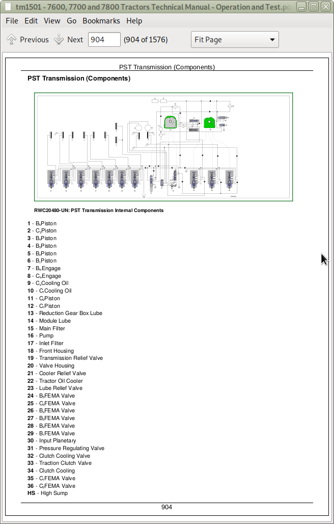
PST Transmission (Components)
Planetary Operation
Test Port/Sensor Location
Element Engagement Chart
Hydraulic Control of Transmission
Electro-Hydraulic (FEMA) Valve
Reduction Gear Box
Power Shift Transmission Schematic (Component Identification)
Section 255: PowrQuad PowrQuad is a trademark of Deere & Company. Transmission
Group 05: PowrQuad PowrQuad is a trademark of Deere & Company. Transmission Operational Checks
Before You Start
Group 10: PowrQuad PowrQuad is a trademark of Deere & Company. Transmission Diagnosis
Use Step-By-Step Hydraulic Diagnostic Charts
Special or Essential Tools
Service Equipment and Tools
Other Material
Transmission Cooler Flow Check
System and Lube Pressure Check
MFWD Clutch Element Leak Check
Avoid High-Pressure Fluids
Adjust for Correct Pressure and Temperature References
Observe Safety Precautions
Shortened Diagnostic Procedure
Major System Checks
Group 20: Theory of Operation
Guide To PowrQuad PowrQuad is a trademark of Deere & Company. Transmission Theory
PowrQuad PowrQuad is a trademark of Deere & Company. Transmission
PowrQuad PowrQuad is a trademark of Deere & Company. Transmission Schematic—Early Version (Component Identification)
PowrQuad PowrQuad is a trademark of Deere & Company. Transmission Schematic—Early Version (Component Identification)
PowrQuad PowrQuad is a trademark of Deere & Company. Transmission Schematic—Later Version
Planetary Operation
Test Port and Sensor Identification
Air Pump
Transmission Oil Pump
Clutch Oil Manifold
Reverse Brake Housing
Filter Relief Valve
Pressure Regulating Valve
Speed Control Circuit
EOV Circuit
Speed Modulator
Shifting From One Speed to Another Using the Speed Control Lever
Speed Lever Moved from Neutral to Second Forward or Second Reverse
FWD-REV Modulation
Shift Lever Moved From Neutral to Forward or Reverse
Shift Lever Moved From Forward or Reverse to Neutral:
Traction Element Cooling Oil Components
Oil Cooler System
Creeper Transmission Operation
Range Box
Section 256: Drive Systems
Group 05: Operational Checks
Drive Systems
Group 10: Drive System Diagnosis
Special or Essential Tools
Avoid High-Pressure Fluids
Differential Lock Leak Check
Rear Differential Diagnosis
PTO Checks
Using MFWD Step By Step Test Procedure
Observe Service Precaution
MFWD Electrical Schematic
Group 20: Adjustments
MFWD Brake Pedal Switch Adjustment
Group 25: Theory of Operation
Differential Lock Operation
Rear Differential Operation
Final Drive Operation
PTO Modulating Valve Operation
Rear PTO
Rear PTO Clutch and Brake Operation
Dual Speed PTO— 1000 RPM Engagement
Dual Speed PTO— 540 RPM Engagement
Two-Speed Shiftable PTO— 1000 RPM Engagement
Two-Speed Shiftable PTO— 540 RPM Engagement
Front PTO
Front PTO Operation
MFWD Clutch Operation
MFWD Axle Operation
MFWD Differential Operation— Limited Slip
Section 260: Steering and Brakes
Group 15: Tests and Adjustments
Brake Operational Test
Group 20: Theory of Operation
Steering System Operation
Hydraulic System— Primary Circuit — Steering and Brakes
Steering Control Valve Assembly
Cutaway View of Steering Valve
Gerotor Operation
Neutral Steering
Right-Turn Steering
Emergency Steering
Gerotor Operation
Ground-Driven Auxiliary Steering Pump
Normal Steering Mode
Brake Pistons, Plates and Disks Operation
Brake Released
Brake Modulation
Brake Engaging
Manual Braking— Prefill
Manual Braking— Engaging
Section 270: Hydraulic System
Group 05: Operational Checks
Before You Start
Group 10: Hydraulic System Diagnosis
Use Step-by-Step Hydraulic Diagnostic Charts
Special or Essential Tools
Service Equipment and Tools
Hydraulic Filter Check
Main Pump Inlet Check
Primary Circuit Pressure Check
Hydraulic Pump Flow Check
Pump Load-Sense Pressure Check
Main Pump Flow Check
Avoid High-Pressure Fluids
Adjust for Correct Pressure and Temperature References
Observe Safety Precautions
Heating Hydraulic Oil
Navigational Flow Chart
Major System Checks—Hydraulics
Additional Troubleshooting Information
Hydraulic System Response to a Missing Shuttle Check Valve
SCV and Coupler Leak Test
Three-Position SCV Lever Kick Out Adjustment
Bleeding Load-Sense and Hydraulic Pressure Circuits
Electro-Hydraulic Depth Control (EHDC) Diagnosis
Hitch Troubleshooting Tips
Come Home Feature
Component Test Specifications
HCU Hardware and Software Information
Hitch Circuit Diagnosis
Test Procedure No. 1—HCU
Diagnostic Codes
HCU Diagnostic Code Numbers
Test Procedure No. 2
HCU Circuit Diagnostic “Beep” Addresses
Test Procedure No. 3
Test Procedure No. 4
Test Procedure No. 5
Test Procedure No. 6
Test Procedure No. 7
Test Procedure No. 8
Test Procedure No. 9
Test Procedure No. 10
Test Procedure No. 11
Test Procedure No. 12
Test Procedure No. 13
Test Procedure No. 14
Test Procedure No. 15
Test Procedure No. 16
Test Procedure No. 17
Adjust Hitch Valve
Test Procedure No. 18
Test Procedure No. 19
Test Procedure No. 20
Test Procedure No. 21
Test Procedure No. 22
Test Procedure No. 23
ROW-TRAK ROW-TRAK is a trademark of Deere & Company. (LHP) Tests
Diagnostic Codes
LHP Diagnostic Code Numbers
Test Procedure No. 2
LHP Circuit Diagnostic “Beep” Addresses
Test Procedure No. 3
Test Procedure No. 4
Test Procedure No. 5
Test Procedure No. 6
Test Procedure No. 7
Test Procedure No. 8
Test Procedure No. 9
Test Procedure No. 10
Test Procedure No. 11
Test Procedure No. 12
Test Procedure No. 13
Test Procedure No. 14
Test Procedure No. 15
Test Procedure No. 16
Test Procedure No. 17
Test Procedure No. 18
Test Procedure No. 19
Test Procedure No. 20
Test Procedure No. 21
Test Procedure No. 22
Test Procedure No. 23
Test Procedure No. 24
Hitch Control Circuit Schematic
Hitch Control Circuit Diagnostic Schematic
Group 15: Calibration and Adjustments
HCU Addresses
Set Hitch Controls for Calibration
LHP Addresses
Prepare ROW-TRAK ROW-TRAK is a trademark of Deere & Company. System for Calibration
Group 20: Theory of Operation
Hydraulic System Components
Hydraulic System Schematic
Hydraulic System Schematic (Component Identification)
Pump Operation
Hydraulic System—Charge Circuit Schematic
Hydraulic Filter Operation
Charge Pump
Hydraulic System Secondary Circuit (Component Identification)
Priority Valve
Neutral—at Start Up
Neutral
Steering Operation
Steering Relief
Steering Returned to Neutral
High Pressure Demand from Secondary
Two-Position Selective Control Valve—Neutral
Two-Position Selective Control Valve—Extend
Two-Position Selective Control Valve—Retract
Two-Position Selective Control Valve—Float
Three-Position Selective Control Valve Operation—Neutral
Three-Position Selective Control Valve Operation—Extend
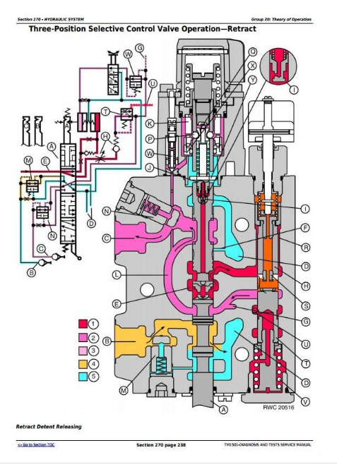
Three-Position Selective Control Valve Operation—Retract
Three-Position Selective Control Valve Operation—Float
ISO Coupler—Closed
ISO Coupler—Coupling
ISO Coupler—Opening
ISO Coupler—Uncoupling
Hitch Control Valve
Pressure and Return Solenoid Valves
Hitch Control Valve—Neutral Position
Pressure Compensator Valve
Load Check Valve
Surge Relief Valve
Hitch Load-Sense Check Valve
Hitch Operation—Raised
Hitch Operation—Stopped
Hitch Operation—Lower
Hitch Operation—Full Lower
Three Point Hitch Hydraulic Operation
Hitch Controls
Electro-Hydraulic Hitch Circuit
Electro-Hydraulic Hitch Sensor Locations
Hitch Control Unit (HCU)
Operator Controls
Hitch Control Lever
Load/Depth Control Potentiometer
Rate-of-Drop Control Potentiometer
Raise Limit Control Potentiometer
Console Raise/Lower Rocker Switch
External Raise/Lower Switch
Hitch Sensing Devices
Hitch Position Feedback Sensor
Load/Draft Sensor
Remote Lift Assist (RLA) and Electro-Hydraulic Depth Control (EHDC) Features
Remote Lift Assist (RLA) Mode
Electro-Hydraulic Depth Control (EHDC)—Optional
Electro-Hydraulic Depth Control (EHDC) Mode
Wiring Harnesses
Hitch Harnesses
Section 290: Operator Station
Group 05: Air Conditioning Operational Checks
Before You Start
Group 10: Air Conditioning System Diagnosis
Service Equipment and Tools
Specifications
Air Conditioning System Components
Air Conditioning System
AQS and Convenience Outlet Circuits Schematic (SE3)
AQS and Convenience Outlet Circuits Diagnostic Schematic (SE3)
Group 25: Air Conditioning Theory of Operation
Refrigerant
Air Conditioning System Air Flow
Air Conditioning System Cycle
Compressor
Condenser
Receiver-Dryer
Expansion Valve
De-Icing Switch
Evaporator
Temperature Control Knob
Compressor On/Off Switch
High and Low Pressure Switches
Section 299: Dealer Fabricated Tools
Group 05: Dealer Fabricated Tools
DFRW2—Needle Valve Test Hose Assembly
DFRW51—Electronic Circuit Load Tester
DFRW85—Reverse Brake Test Plate
DFRW86—Spool Holding Tool
DFRW60 - DFRW61 - DFRW62—Extension Harnesses
DFRW63 - DFRW64 - DFRW65 - DFRW66 - DFRW81—Tap-Out Harnesses
John Deere Tractors 7600, 7700, 7800 Diagnosis and Tests Service Technical Manual (TM1501)
![]()