
John Deere 2WD or MFWD Tractors 7720, 7820, 7920 Repair Service Manual (TM2080)
Complete Repair Service Technical Manual for John Deere 7720, 7820, 7920 Tractors, with all the workshop information to maintain, repair, and service like professional mechanics.
John Deere 2WD or MFWD Tractors 7720, 7820, 7920 workshop technical manual (repair) includes:
* Numbered table of contents easy to use so that you can find the information you need fast.
* Detailed sub-steps expand on repair procedure information
* Numbered instructions guide you through every repair procedure step by step.
* Notes, cautions and warnings throughout each chapter pinpoint critical information.
* Bold figure number help you quickly match illustrations with instructions.
* Detailed illustrations, drawings and photos guide you through every procedure.
* Enlarged inset helps you identify and examine parts in detail.
tm2080 - 7720 7820 7920 Tractors Technical Manual.pdf
tm2080 - 7720 7820 7920 Tractors Technical Manual.epub
Total Pages: 1,710 pages
File Format: PDF/EPUB/MOBI/AZW (PC/Mac/Android/Kindle/iPhone/iPad; bookmarked, ToC, Searchable, Printable)
Language: English
MAIN SECTIONS
Foreword
Notice to Dealers
Dealer Predelivery Information Form
General Information
Safety
General Information
General Specifications
Engine
Component Removal and Installation
Engine Repair
Fuel / Air Intake and Cooling Systems
Controls
Diesel Fuel System
Air Intake System
Engine Cooling System
Standard Cooler and Air Conditioning Condenser
Deluxe Cooler and Air Conditioning Condenser
Exhaust System
Electrical
Connectors
Wiring Harness Routings
Charging Circuit
Starting Circuit
Solenoids and Switches
Monitoring System
Armrest Control
Auxiliary Lighting and Electrical Components
Convenience and Accessory Components
PowrQuad-Plus Transmission
Component Removal and Installation
Transmission Shifting Mechanisms
PowrQuad-Plus Module
Range Box
AutoPowr/IVT Transmission
Component Removal
Controls
Front Pump/Control Valve Assembly
Transmission Front Housing
Hydrostatic Module
Shift Valve Assembly
Transmission Rear Housing
Differential Input Assembly
MFWD Drive Systems
Component Removal And Installation
Controls
MFWD Clutch
MFWD Axle
Suspended MFWD Axle Components
Drive Systems
Component Removal And Installation
Rear Differential
Final Drive
Rear PTO
Front PTO Repairs
Primary Brakes
Steering and Brakes
Steering Column
Hydrostatic Steering
Service Brakes
Trailer Brakes
Hydraulics
Component Removal and Installation
Hydraulic System Repair
Hydraulic Pump And Charge Pump
Hydraulic System Valves
Selective Control Valves and Couplers
Rear 3-Point Hitch
Front 3-Point Hitch
Bleed Hydraulic System
Miscellaneous
Hood
Front Axle (Two-Wheel Drive)
Steering Cylinders (Two-Wheel Drive)
Rear Wheels
Wagon And Pick-Up Hitch
Operator Station
Component Removal and Installation
Heating, Ventilating, and Air Conditioning (HVAC)
Air Conditioning System
Air Suspension Seat
ACTIVE SEAT™
Armrest
Cab Door and Windshield
Dealer Fabricated Tools
DFRW
tm2080 - 7720 7820 7920 Tractors
Table of Contents
Foreword
Notice to Dealers
Dealer Predelivery Information Form
Section 10: General Information
Group 05: Safety
Recognize Safety Information
Handle Fuel Safely—Avoid Fires
Prevent Battery Explosions
Prepare for Emergencies
Prevent Acid Burns
Handle Chemical Products Safely
Avoid High-Pressure Fluids
Park Machine Safely
Support Machine Properly
Wear Protective Clothing
Work in Clean Area
Service Machines Safely
Work In Ventilated Area
Illuminate Work Area Safely
Replace Safety Signs
Use Proper Lifting Equipment
Service Tires Safely
Avoid Harmful Asbestos Dust
Avoid Heating Near Pressurized Fluid Lines
Remove Paint Before Welding or Heating
Use Proper Tools
Construct Dealer-Made Tools Safely
Dispose of Waste Properly
Live With Safety
Service Accumulator Systems Safely
Wait Before Opening High-Pressure Fuel System
Group 10: General Information
Sealants and Adhesives Cross-Reference Chart
Identify Zinc-Flake Coated Fasteners
Unified Inch Bolt and Screw Torque Values
Metric Bolt and Screw Torque Values
Glossary of Terms
Group 15: General Specifications
Specifications (North America, Latin America, South Africa, and Asia)
Specifications (Europe)
Section 20: Engine
Group 00: Component Removal and Installation
Essential or Recommended Tools
Other Material
Specifications
Remove and Install 6.8L—Engine
Remove and Install 8.1L—Engine
Group 05: Engine Repair
Specifications
Repair Engine—Use CTM
Access to Front Crankshaft Seal
Access to Rear Crankshaft Seal
Access to Camshaft
Access to Timing Gear Cover
Access to Engine Oil Pan
Repair 6.8L Engine Accessory Drive Assembly
Remove and Install 6.8L Engine Valve Cover
Remove and Install 8.1L Engine Valve Cover
Section 30: Fuel / Air Intake and Cooling Systems
Group 05: Controls
Repair Engine—Use CTM
Group 10: Diesel Fuel System
Specifications
Remove and Install Fuel Tanks
Replace Fuel Filter, Fuel Pump, and Bleed Fuel System
Group 15: Air Intake System
Specifications
Inspect and Service Air Intake System
Group 20: Engine Cooling System
Essential or Recommended Tools
Specifications
Test Radiator and Coolant Tank Cap
Remove and Install Radiator/Aftercooler
Inspect Belt Tensioner
Remove and Install Viscous Fan Drive
Remove and Install Vistronic Fan Drive
Fan Belt Routing—7720 to 7920
Group 25: Standard Cooler and Air Conditioning Condenser
Essential or Recommended Tools
Specifications
Remove Fuel-Hydraulic Oil Cooler/Condenser
Leak Test Fuel-Hydraulic Oil Cooler
Install Fuel-Hydraulic Oil Cooler/Condenser
Group 30: Deluxe Cooler and Air Conditioning Condenser
Essential or Recommended Tools
Specifications
Other Material
Remove Air Conditioning Condenser/Fuel Cooler
Install Air Conditioning Condenser/Fuel Cooler
Replace Hydraulic Oil Cooler
Leak Test Hydraulic Oil Cooler
Group 35: Exhaust System
Specifications
Remove and Install Exhaust System
Section 40: Electrical
Group 05: Connectors
Essential or Recommended Tools
Other Material
Use Electrical Insulating Compound
Using High-Pressure Washers
Repair AMP Injection Pump Connector
Remove Connector Body from Blade Terminals
Repair CINCH Connectors
Repair 32 and 48 Way CINCH Connectors
Repair CPC Blade Type Connectors
Repair CPC, Large MATE-N-LOC MATE-N-LOC is a trademark of AMP Incorporated and METRIMATE METRIMATE is a trademark of AMP Incorporated Pin Type Connectors
Repair DEUTSCH Connectors
Repair ITT Connector
Repair Small MATE-N-LOC Socket Connector
Repair Small MATE-N-LOC Pin Connector
Repair (Pull Type) METRI-PACK METRI-PACK is a trademark of Delphi Packard Electric Systems Connectors
Repair (Push Type) METRI-PACK Connectors
Repair Molex Connector
Repair SUMITOMO™ Connectors
Repair Weather Pack Weather Pack is a trademark of Packard Electric Connector
Repair YAZAKI™ Connectors
Group 10: Wiring Harness Routings
Ground Point Locations
Cab Harness Routing—(POWRQUAD-PLUS or AUTOQUAD-PLUS)
Cab Harness Routing—(AUTOPOWR/IVT)
Main Armrest Control Unit (ACU) Harness Routing
Armrest Control Unit (ACU) Harness Routing
Outer Cab Roof Harness Routing
Loader Light Harness
Hood Light Harness (North American)
Hood Light Harness (European)
Hood Light Harness (HID)
ActiveSeat ActiveSeat is a trademark of Deere & Company Harness Routing—(POWRQUAD-PLUS or AUTOQUAD-PLUS)
ActiveSeat ActiveSeat is a trademark of Deere & Company Harness Routing Harness Routing—(AUTOPOWR/IVT)
Heated Seat Harness
Loader Joystick Harness Routing—(Cab)
Front PTO Harness Routing—(Cab)
Manual A/C Harness Routing
ClimaTrak ClimaTrak is a trademark of Deere & Company Harness Routing
Right-Hand Console Harness Routing—(North American)
Right-Hand Console Harness Routing—(European)
Engine/Chassis Harness Routing and Component Identification (6.8L)—POWRQUAD-PLUS or AUTOQUAD-PLUS
Engine/Chassis Harness Routing and Component Identification (8.1L)—POWRQUAD-PLUS or AUTOQUAD-PLUS
Engine/Chassis Harness Routing and Component Identification (6.8 L)— AutoPowr is a trademark of Deere & Company /IVT
Engine/Chassis Harness Routing and Component Identification (8.1 L) AutoPowr is a trademark of Deere & Company /IVT
Harness Routing—Front PTO
Harness Routing—Suspended MFWD Axle and Front Brakes
Harness Routing—SCV 5 & 6, Grapple, Loader, and Front Hitch
Harness Routing—Tractor Equipment Control Unit (TECU)
Transmission Harness Routing and Component Identification—POWRQUAD-PLUS or AUTOQUAD-PLUS
Transmission Harness Routing and Component Identification— AutoPowr is a trademark of Deere & Company /IVT
Wire Number and Color Codes
Load Center Panel—(North American)
Load Center Panel—(European)
Relay Panel—(Lights, Wipers, and A/C)
Replace Load Center Fuses and Relays
Group 15: Charging Circuit
Repair Alternator—Use CTM
Exploded View—Alternator
Remove and Install Alternator
Group 20: Starting Circuit
Essential or Recommended Tools
Specifications
Repair Starter—Use CTM
Remove and Install Starter Motor
Replace Starter Circuit Relay
Replace Fusible Link
Group 25: Solenoids and Switches
Specifications
Replace Ether Starting Aid Solenoid and Switch
Replace Brake Switch—Non-AUTOPOWR/IVT
Replace Brake Switch
Replace MFWD Switch
Replace MFWD Solenoid
Replace Differential Lock Switch
Replace Rear PTO Shaft Select Switch
Replace Differential Lock and Rear PTO Solenoids
Replace Hitch Raise and Lower Solenoids
Replace Hitch Position Potentiometer Assembly
Replace Clutch Pedal Position Sensor
Remove Electrical Switches, Sensors and Solenoids—POWRQUAD-PLUS or AUTOQUAD-PLUS Transmissions
Electrical Controls and Switches—AutoPowr™/IVT™ Transmission
Replace AutoPowr™/IVT™ Hydro Control Solenoid
Replace AutoPowr™/IVT™ Fixed Unit Speed Sensor
Replace AutoPowr™/IVT™ Carrier Speed Sensor
Replace AUTOPOWR/IVT Hand Throttle/Speed Selector Assembly
Replace AUTOPOWR/IVT Set-Speed Switch
Replace SCV Control Lever
Group 30: Monitoring System
Essential or Recommended Tools
Other Material
Replace Engine Oil Pressure Sensor
Replace Engine Crank Speed Sensor
Replace Engine Coolant Temperature Sensor
Replace Air Filter Restriction Indicator Sensor
Replace Fuel Level Sensor
Replace Hydraulic Oil Filter Restriction Sensor
Remove and Install Draft Link Sensor
Adjust Draft Link Sensor
Replace Rear PTO Speed Sensor
Replace Radar Speed Sensor
Replace MFWD Speed Sensor—AutoPowr™/IVT™
Replace AutoPowr™/IVT™ Primary Wheel Speed Sensor
Replace AutoPowr™/IVT™ Backup Wheel Speed Sensor
Replace AutoPowr™/IVT™ Transmission Oil Temperature Sensor
Replace AutoPowr™/IVT™ Transmission Pressure Sensor
Replacing Front Console Display Light Bulbs
Replacing Corner Post Display Light Bulbs
Replacing CommandCenter Display Light Bulbs
Replacing SCV TOUCHSET TOUCHSET is a trademark of Deere & Company Control Display Light Bulbs
Group 35: Armrest Control
List of References
Armrest Test Procedures
Replace Armrest Control Assembly
Replace Armrest Control Unit (ACU)
Replace Engine Speed Control
Replace Transmission Control (IVT)
Replace SCV Control Lever
Replace Hitch Control
Replace Rear PTO Switch
Replace IMS Switch
Replace Resume Switch
Group 40: Auxiliary Lighting and Electrical Components
Replace Seven-Terminal Outlet Socket—North American
Replace Seven-Terminal Outlet Socket—European
Group 45: Convenience and Accessory Components
Essential or Recommended Tools
Replace Circulation Blower Motor
Replace Heating, Ventilating, and Air Conditioning (HVAC) Pressurizer Blower Motor
Replace Wiper Motor
Test Ground-Fault Circuit Interrupter
Replace Hydraulic Charge Pump Heater
Section 50: PowrQuad-Plus Transmission
Group 00: Component Removal and Installation
Essential or Recommended Tools
Other Material
Specifications
Sealing Instructions—Drive Train
Remove Drive Train
Install Drive Train
Remove Transmission
Install Transmission
Remove Range Box
Install Range Box
Group 05: Transmission Shifting Mechanisms
Specifications
Repair Range Shift Linkage (PowrQuad-Plus PowrQuad-Plus is a trademark of Deere & Company Transmissions)
Remove and Install Shift Cables
Check And Adjust Shift Cables (PowrQuad-Plus PowrQuad-Plus is a trademark of Deere & Company Transmissions)
Group 10: PowrQuad-Plus Module
Essential or Recommended Tools
Specifications
Replace Temperature Sensor And Pressure Switches
Remove And Install Valves In Front Transmission Cover
Repair Shift Valve Housing
Remove And Install Front Transmission Cover
Remove Hydraulic Pump Drive
Repair Hydraulic Pump Drive
Install Hydraulic Pump Drive
Remove And Install Front Valve Housing
Remove Transmission Oil Pump
Exploded View—Transmission Oil Pump
Repair Transmission Oil Pump
Install Transmission Oil Pump
Remove Gear-Shift Planetary Drive
Exploded View—Planetary Drive
Repair Gear-Shift Planetary Drive
Install Gear-Shift Planetary Drive
Remove B1 Brake Housing
Recondition B1 Brake
Install B1 Brake Housing
Remove B2-B3 Brake Housing
Recondition B2 Brake
Recondition B3 Brake
Install B2-B3 Brake Housing
Remove C4 Clutch
Cross Sectional View—C4 Clutch
Exploded View—C4 Clutch
Repair C4 clutch
Install C4 Clutch
Remove Reverse Brake
Exploded View—Reverse Brake
Repair Reverse Brake
Install Reverse Brake
Remove Forward Clutch With Planetary Drive (Forward/Reverse)
Cross Sectional View—Forward Clutch with Planetary Drive
Exploded View—Forward Clutch with Planetary Drive
Repair Forward Clutch With Planetary Drive (Forward/Reverse)
Install Forward Clutch With Planetary Drive (Forward/Reverse)
Exploded View—Output Shaft
Replace Output Shaft
Group 20: Range Box
Essential or Recommended Tools
Specifications
Cross Sectional View—Range Box
Cross Sectional View—Shifter Assembly
Exploded View—Drive Shaft 40 km/h (25 mph)
Exploded View—Drive Shaft 50 km/h (31 mph)
Exploded View—Differential Drive Shaft 40 km/h (28 mph) and 50 km/h (31 mph)
Repair Range Box
Repair Shift Cover
Replace Speed Sensor
Section 51: AutoPowr/IVT Transmission
Group 00: Component Removal
Essential or Recommended Tools
Specifications
Remove and Install Transmission
Group 05: Controls
Essential or Recommended Tools
Specifications
Brake Pedal Switch Adjustment
Using Hydraulic Hand Pump to Release Park Brake
Adjust Service Disconnect
Group 10: Front Pump/Control Valve Assembly
Essential or Recommended Tools
Specifications
Remove, Repair, and Install Hydraulic Pump Drive
General Repair Procedures—Front Control Valve/Transmission Control Pump Assembly
Remove and Install Front Control Valve Assembly
Exploded View—Front Control Valve Assembly
Repair Front Control Valve Assembly
Group 15: Transmission Front Housing
Essential or Recommended Tools
Specifications
Other Material
General Repair Procedures—Transmission
Hydrostatic Module Replacement
Repair Sequence for Hydrostatic Module Service ONLY
Remove Hydrostatic Module
Install Hydrostatic Module
Group 20: Hydrostatic Module
Essential Tools
Specifications
Exploded View—Hydrostatic Gear Train
Disassemble Hydrostatic Module Gear Train
Repair Hydrostatic Module Gear Train
Assemble Hydrostatic Module Gear Train
Replace Hydrostatic Module
Test Multi-Function Valves
Repair Hydrostatic Module
Group 25: Shift Valve Assembly
Essential or Recommended Tools
Specifications
General Repair Procedures—Shift Control Valve Assembly
Remove and Install Shift Valve Housing
Exploded View—Shift Valve Housing
Repair Shift Valve Assembly
Service Hi-Lo-Reverse Shift Valves
Air Leak Check Procedure
Group 30: Transmission Rear Housing
Essential Tools
Specifications
Transmission Rear Housing
Cross-Sectional View—Park Brake Assembly
Repair Park Brake
Remove And Install Clutch/Planetary Assembly
Shift Accumulator
Cross Sectional View—Clutch Assembly
Cross Sectional View—Clutch/Planetary Assembly
Exploded View—Planetary Assembly
Repair Clutch/Planetary Assembly
Repair Reverse Brake
Replace Clutch/Planetary Carrier Bearing Cups
Group 35: Differential Input Assembly
Essential or Recommended Tools
Specifications
General Repair Procedures—Differential Input Assembly
Cross-Sectional View—Differential Input Assembly
Disassemble Differential Input Assembly
Determine Cone Point Shim Pack and Install Differential Drive Shaft
Assemble Differential Input Assembly
Section 56: MFWD Drive Systems
Group 00: Component Removal And Installation
Essential or Recommended Tools
Other Material
Specifications
Sealing Instructions
Remove MFWD Clutch
Install MFWD Clutch
Remove Non-Suspended MFWD Axle
Install Non-Suspended MFWD Axle
Remove Suspended MFWD Axle
Install Suspended Axle
Group 05: Controls
Specifications
PTO Shift Lever
Group 10: MFWD Clutch
Specifications
General Repair Procedures—MFWD Clutch
Cross-Sectional View—MFWD Clutch Without Secondary Brake (POWRQUAD-PLUS™ or AUTOQUAD-PLUS™)
Cross-Sectional View—MFWD Clutch With Secondary Brake (POWRQUAD-PLUS™ or AUTOQUAD-PLUS™)`
Cross-Sectional View—MFWD Clutch Without Secondary Brake (AutoPowr/IVT)
Cross-Sectional View—MFWD Clutch With Secondary Brake (AutoPowr/IVT)
Disassemble MFWD Clutch
Disassemble MFWD Clutch Pack
Assemble MFWD Clutch Pack
Assemble MFWD Clutch
Group 15: MFWD Axle
Essential or Recommended Tools
Other Material
Specifications
Cross-Sectional View—Planetary Carrier and Wheel Hub Without Brake
Cross-Sectional View—Planetary Carrier and Wheel Hub With Brake
Remove, Recondition, And Install Planetary Carrier And Wheel Hub Without Brake
Remove, Recondition, And Install Planetary Carrier And Wheel Hub With Brake
Cross-Sectional View—Knuckle Spindle Assembly (Standard Duty)
Cross-Sectional View—Knuckle Spindle Assembly (Heavy Duty)
Disassemble, Inspect, and Assemble Knuckle Spindle Assembly
Install Non-Suspended MFWD Axle Into Repair Stand
Install Suspended MFWD Axle Into Repair Stand
Remove And Install Planetary Carrier-Wheel Hub-Knuckle Spindle—U-Joint/Axle Shaft Assembly
Determine Kingpin Shim Pack
Remove Differential Housing
Cross-Sectional View—Differential Housing—Standard Limited Slip Differential
Cross-Sectional View—Differential Housing—Heavy Duty Limited Slip Differential/Suspended Axle
Cross-Sectional View—Differential Housing—Heavy Duty Limited Slip Differential
Cross-Sectional View—Differential Housing—Heavy Duty Limited Slip Differential/Suspended Axle
Cross-Sectional View—Differential Housing—Heavy Duty With Hydraulic Differential Lock
Repair Differential Housing—Limited Slip Differential
Assemble Differential—Limited Slip Differential
Repair Differential Housing—With Hydraulic Differential Lock
Assemble Differential—With Hydraulic Differential Lock
Cross-Sectional View—Differential Drive Shaft and Input Quill—Non-Suspended MFWD Axle
Cross-Sectional View—Differential Drive Shaft And Input Quill—Suspended MFWD Axle
Remove And Disassemble Differential Drive Shaft
Determine Differential Drive Shaft Cone Point Shim Pack
Assemble And Install Differential Drive Shaft
Check Ring Gear Backlash And Determine Differential Case Bearing Cup Shim Pack—Limited Slip
Check Ring Gear Backlash And Determine Differential Case Bearing Cup Shim Pack—Locking
Adjust Ring Gear Backlash
Backlash Shim Pack Example and Worksheet
Install Differential Case Bearing Cup and Differential Housing
Disassemble And Assemble Axle Housing—Standard Duty
Disassemble Axle Housing—Heavy Duty
Determine And Install Axle Housing Bearing Cup Shim Pack—Standard Duty
Preload Shim Pack Example And Worksheet
Determine And Install Axle Housing Bearing Cup Shim Pack—Heavy Duty
Preload Shim Pack Example And Worksheet
Install Axle Housing
Cross-Sectional View—Steering Cylinder Housing Assembly—Non-Suspended MFWD Axle
Cross-Sectional View—Steering Cylinder Housing Assembly—Suspended MFWD Axle
Remove And Disassemble Steering Cylinder
Cross-Sectional View—Steering Cylinder
Assemble And Install Steering Cylinder
Replace MFWD Pivot Bushing
Group 16: Suspended MFWD Axle Components
Essential or Recommended Tools
Exploded View—Suspended Axle Control Valve
Relieve Pressure From Suspended MFWD Axle Hydraulic System
Replace Suspended MFWD Axle Position Sensor
Recondition Suspended MFWD Axle Pressure Control, Pressure Relief, And Solenoid Valves
Cross-Sectional View—Suspended MFWD Axle Cylinder Piston Seals
Check and Charge Accumulators
Section 57: Drive Systems
Group 00: Component Removal And Installation
Essential or Recommended Tools
Other Material
Specifications
Sealing Instructions
Remove Front PTO Assembly
Install Front PTO Assembly
Remove Final Drive
Install Final Drive
Remove Rear PTO Assembly
Install Rear PTO Assembly
Group 10: Rear Differential
Essential Or Recommended Tools
Specifications
General Repair Procedures—Rear Differential
Remove Differential
Cross-Sectional View—Differential
Disassemble Differential
Assemble Differential
Adjust Differential Preload
Adjust Differential Backlash
Group 20: Final Drive
Essential Or Recommended Tools
Other Material
Specifications
General Repair Procedures—Final Drive
Remove Planet Pinion Carrier
Cross-Sectional View—Planet Pinion Carrier
Disassemble Planet Pinion Carrier
Exploded View—Planet Pinion Carrier
Assemble Planet Pinion Carrier
Cross-Sectional View—92 mm Rear Axle Housing And Shaft
Cross-Sectional View—100 mm Rear Axle Housing And Shaft
Remove Axle Housing
Disassemble And Assemble Axle Housing
Disassemble And Assemble Axle Shaft
Install Axle Housing
Install Planet Pinion Carrier And Check Rolling Drag Torque (Non-Shimmed Axles)
Install Planet Pinion Carrier And Check Rolling Drag Torque (Shimmed Axles)
Group 30: Rear PTO
Essential or Recommended Tools
Other Material
Specifications
General Repair Procedures—PTO
Cross-Sectional View—PTO Clutch
Remove And Disassemble PTO Clutch
Assemble And Install PTO Clutch
Remove And Disassemble Output Shaft and PTO Shifter
Remove And Disassemble Countershaft
Cross-Sectional View—Two-Speed Shiftable PTO Countershaft
Cross-Sectional View—Three-Speed Shiftable PTO Countershaft
Assemble And Install Countershaft
Cross-Sectional View—Single-Speed PTO Output Shaft
Cross-Sectional View—Two-Speed Shiftable PTO Output Shaft
Cross-Sectional View—Three-Speed Shiftable PTO Output Shaft
Assemble And Install PTO Output Shaft and PTO Shifter
Exploded View—Shiftable PTO Shifter
Install Shifter
Replace PTO Output Shaft Oil Seal
Remove 540/1000 PTO Adapter Assembly
Disassemble and Assemble 540/1000 PTO Adapter Assembly
Install 540/1000 PTO Adapter Assembly
Group 35: Front PTO Repairs
Essential or Recommended Tools
Other Material
Specifications
General Repair Procedures—PTO
Exploded View—Front PTO Driveline
Repair Front PTO Driveline
Remove and Install Front PTO Oil Filter and Cooler
Remove and Install Front PTO Pump
Remove Front PTO Clutch Housing
Disassemble Front PTO Clutch Housing
Assemble Front PTO Clutch Housing
Replace Front PTO Brake
Remove Front PTO Output Shaft
Install Front PTO Output Shaft
Remove and Install Modulating Valve
Repair Pressure Regulating Valve
Repair Oil Cooler Bypass and Lube Relief Valves
Disassemble Front PTO Gearcase Housing
Group 40: Primary Brakes
Essential or Recommended Tools
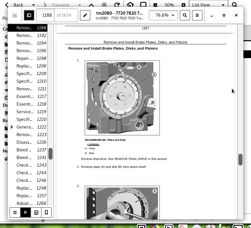
Remove and Install Brake Plates, Disks, and Pistons
Section 60: Steering and Brakes
Group 05: Steering Column
Remove Cowl and Plenum
Repair Steering Column (Standard and AutoTrac)
Replace Clutch Pedal Return Spring
Group 10: Hydrostatic Steering
Specifications
Remove and Install Steering Control Assembly (Standard and AutoTrac)
Group 15: Service Brakes
Essential Tools
Service Parts Kits
Specifications
General Repair Procedures—Brake Valve
Remove and Install Brake Valve
Disassemble, Inspect, and Assemble Brake Valve
Bleed Brakes
Bleed MFWD Brakes
Check Manual Brakes (Without Trailer Brakes)
Check Manual Brakes (With Air Trailer Brakes Only)
Check Manual Brakes (With Hydraulic Trailer Brakes Only)
Group 20: Trailer Brakes
Replace Hand Brake Cable
Adjust Air Brake and Hand Brake
Section 70: Hydraulics
Group 00: Component Removal and Installation
Specifications
Remove and Install Hydraulic Pump
Remove And Install Hitch Valve
Remove and Install Deluxe SCVs
Remove and Install Mid-Stack
Remove and Install SCV Valve Stack and Couplers
Group 05: Hydraulic System Repair
Essential or Recommended Tools
General Repair Procedures—Hydraulic System
Specifications
Use Special Wrench
Install Hydraulic Fittings
Group 10: Hydraulic Pump And Charge Pump
Other Material
Specifications
Remove And Install Hydraulic Pump Controller
Repair Hydraulic Pump Controller
Exploded View—Hydraulic Pump
Disassemble, Inspect, and Assemble Hydraulic Pump
Exploded View—Hydraulic Charge Pump
Group 15: Hydraulic System Valves
Specifications
General Repair Procedures—Hitch and Inlet-Priority Valves
Disassemble, Inspect, and Assemble Inlet-Priority Valve
Exploded View—Hitch Valve
Disassemble, Inspect, and Assemble Hitch Valve
Test Surge Relief Valve
Group 20: Selective Control Valves and Couplers
Essential or Recommended Tools
Specifications
General Repair Procedures—Selective Control Valves
Remove, Install, And Adjust Cables—Manual SCV
Exploded View—Manual Selective Control Valve (Three-Postion)
Replace Control Knob—Manual SCV
Inspect Poppet Load-Check Valves—Manual SCV
Inspect Pressure Compensator Valve—Manual SCV
Inspect Metering Valve—Manual SCV
Disassemble, Inspect, And Assemble Control Valve—Manual SCV
Exploded View—Deluxe SCV
Repair Deluxe SCVs
Rear Hydraulic Couplers (Deluxe)—Repair
Remove and Install Mid-Stack Couplers
Disassemble and Assemble Mid-Stack
Repair Directional Valve
Group 30: Rear 3-Point Hitch
Essential or Recommended Tools
Specifications
Remove and Install Hitch Lift Cylinders
Cross-Sectional View—Lift Cylinder
Disassemble, Inspect, and Assemble Lift Cylinder
Remove and Install Rockshaft Support Housing
Remove and Install Rockshaft
Replace Rockshaft Housing Bushings
Repair Draft Sensing Shaft
Repair Draft Link
Group 35: Front 3-Point Hitch
Essential or Recommended Tools
Specifications
Exploded View—Front 3-Point Hitch
Exploded View—Front Hitch Lift Cylinder
Repair Front Hitch Lift Cylinder
Group 40: Bleed Hydraulic System
Essential or Recommended Tools
Bleed Hydraulic System
Section 80: Miscellaneous
Group 05: Hood
Specifications
Remove and Install Hood
Group 10: Front Axle (Two-Wheel Drive)
Essential or Recommended Tools
Specifications
Other Material
Remove Front Axle (Two-Wheel Drive)
Install Front Axle (Two-Wheel Drive)
Replace Knee Bushings
Replace Wheel Bearings
Group 15: Steering Cylinders (Two-Wheel Drive)
Other Material
Service Parts Kits
Specifications
Remove and Install Steering Cylinder (Two-Wheel Drive)
Cross-Sectional and Exploded View—Steering Cylinder—Two-Wheel Drive
Group 20: Rear Wheels
Service Heavy-Duty Wheel Clamps
Group 25: Wagon And Pick-Up Hitch
Specifications
Repair Wagon Hitch
Adjust Wagon Hitch Release
Repair Pick-Up Hitch
Adjust Pick-Up Hitch
Section 90: Operator Station
Group 00: Component Removal and Installation
Essential or Recommended Tools
Specifications
Remove Cab
Install Cab
Repair Cab
Group 05: Heating, Ventilating, and Air Conditioning (HVAC)
Heater Line Routing
Remove HVAC Module
Install HVAC Module
Remove and Install Heater Core
Remove and Install Heater Control Valve (Without CLIMATRAK)
Remove and Install Heater Control Valve (With CLIMATRAK)
Leak Test Manual Heater Control Valve
Install Heater Control Valve
Remove and Install Control Cable
Adjust Heating/Cooling Controls
Group 10: Air Conditioning System
Essential or Recommended Tools
Other Material
Specifications
Service Parts Kits
Hose and Tubing O-Ring Connection Torques
Diagram—Air Conditioning System
Reference Chart—Fittings—Air Conditioning System
Discharge Air Conditioning System
Flushing, Purging, and Evacuating Information
Flush Air Conditioning System
Purge Air Conditioning System
Evacuate Air Conditioning System
Charge Air Conditioning System
Refrigerant Oil Information
Check Compressor Oil Charge
Determine Correct Refrigerant Oil Charge
Add Refrigerant Oil to System
Add Refrigerant Oil to Pressurized System
Remove and Install Compressor
Test Volumetric Efficiency
Test Shaft Seal Leakage
Disassemble and Assemble Compressor Clutch
Check Clutch Hub Clearance
Inspect Compressor Manifold
Disassemble, Inspect, and Assemble Compressor
Remove and Install Compressor Relief Valve
Replace Receiver-Dryer
Remove and Install Expansion Valve
Remove Air Conditioning Condenser
Leak Test Condenser
Leak Test Evaporator
Remove and Install Evaporator
Group 15: Air Suspension Seat
Essential or Recommended Tools
Other Material
Specifications
Remove and Install Seat
Repair Seat Air System
Repair Seat Suspension
Repair Seat Back
Repair Seat Control Knobs
Group 20: ACTIVE SEAT™
Essential or Recommended Tools
Other Material
Specifications
Purging Air from ACTIVE SEAT ACTIVE SEAT is a trademark of Deere & Company System
Remove and Install ACTIVE SEAT ACTIVE SEAT is a trademark of Deere & Company
Remove and Install ACTIVE SEAT Actuator
Remove and Install Actuator Hoses
Remove and Install Seat Control Valve Assembly
Remove and Install Accumulator
Checking and Charging Replacement Accumulators
Repair ACTIVE SEAT Air System
Repair Active Seat Suspension
Repair Seat Back
Group 25: Armrest
Remove and Install Armrest Control
Disassemble and Assemble Armrest Adjustment Assembly
Group 30: Cab Door and Windshield
Specifications
Repair Cab Door Latch
Cab Door Adjustment—Step 1
Cab Door Adjustment—Step 2
Cab Door Adjustment—Step 3
Cab Door Adjustment—Step 4
Replace Windshield Glass or Seal
Section 99: Dealer Fabricated Tools
Group 05: DFRW
DFRW20—Compressor Holding Fixture
DFRW30A—Axle Jacking Tool
DFRW87—Pick-Up Hitch Adapter Plate
DFRW92—Mounting Guide Pins
DFRW132—Differential Side Bevel Gear End Play Tool
DFRW139—Evaporator Flushing Block
DFRW148—ACTIVE SEAT™ Control Valve Holding Tool
DFRW151—Radiator Cap Adapter
DFRW156—Shift Valve Bore Flushing Can
DFRW168 — Park Solenoid Jumper Harness
DFRW179—Front PTO Support Bracket
DFRW182—Cone Stand Adapter
DFRW193—Modification to JT01730 Rear PTO Removal Bracket to a JT01730A
DFRW194—MFWD Input Shaft Holding Tool
DFRW212 Leak Test Assembly
John Deere 2WD or MFWD Tractors 7720, 7820, 7920 Repair Service Manual (TM2080)
![]()