
John Deere Tractors 6415, 6615, 7515 Diagnosis and Tests Service Technical Manual (TM8128)
Complete Diagnosis & Tests Technical Manual with electrical wiring diagrams for John Deere 2WD or MFWD - Brazil Tractors 6415, 6615, 7515, with all the shop information to maintain, diagnose, repair, and service like professional mechanics.
John Deere Tractors 6415, 6615, 7515 workshop Diagnosis & Tests technical manual includes:
* Numbered table of contents easy to use so that you can find the information you need fast.
* Detailed sub-steps expand on repair procedure information
* Numbered instructions guide you through every repair procedure step by step.
* Troubleshooting and electrical service procedures are combined with detailed wiring diagrams for ease of use.
* Notes, cautions and warnings throughout each chapter pinpoint critical information.
* Bold figure number help you quickly match illustrations with instructions.
* Detailed illustrations, drawings and photos guide you through every procedure.
* Enlarged inset helps you identify and examine parts in detail.
tm8128 - 6415, 6615 and 7515 Tractors Technical Manual.pdf
PRODUCT DETAILS:
Total Pages: 1,633 pages
File Format: PDF (bookmarked, ToC, Searchable, Printable, high quality)
Language: English
MAIN SECTIONS
Foreword
Recognize Safety Information
Follow Safety Instructions
Replace Safety Signs
Wear Protective Clothing
Prevent Battery Explosions
Service Tires Safely
Keep ROPS Installed Properly
Park Machine Safely
Handle Fluids Safely-Avoid Fires
Handle Fuel Safely-Avoid Fires
Prepare for Emergencies
Work in Clean Area
Prevent Machine Runaway
Work In Ventilated Area
Avoid High-Pressure Fluids
Use Proper Lifting Equipment
Illuminate Work Area Safely
Use Proper Tools
Live With Safety
General Information
Safety Measures
General References
Diagnostic Trouble Codes
BCU Diagnostic Trouble Codes
Observable Symptoms
Electrical System
SyncroPlus Transmission
PowrQuad Transmissions
Drive Systems
Steering and Brakes
Hydraulic System
Operator`s Cab
System Diagnosis
Electronics
Engine
Operational Checks
Tests and Adjustments
Fuel, Air Intake and Cooling Systems
Tests and Adjustments
Operational Theory
Electrical System - Cab Tractors
Fuse Box
Starting and Charging Circuit
Panel Warning Lights
Lights and Tail Lights
Work Lights
Radio, Dome Light, Console Light and Beacon Light
Horn and Accessories Socket
Fan and A/C
Reverse Light and Backup Alarm
Front Windshield Wiper and Washer
Rear Windshield Wiper and Washer
Trailer Connector
BCU - Turn Signal and Hazard Warning Lights
BCU - Electronic Hitch-Control - 6415/6615
BCU - Electronic Hitch-Control - 7515
BCU - Brakes
BCU - Service Connector
BCU - PTO
BCU - Engine Speed Sensor
BCU - Front-Wheel Drive
BCU - Differential Lock
Component Tests
Connectors
Electrical System - Open Operator`s Station
Fuse Box
Starting and Charging Circuit
Panel Warning Lights
Lights and Tail Lights
Work Lights
Horn
Reverse Light and Backup Alarm
Trailer Connector
BCU - Turn Signal and Hazard Warning Lights
BCU - Electronic Hitch-Control - 6415/6615
BCU - Electronic Hitch-Control - 7515
BCU - Brakes
BCU - Service Connector
BCU - PTO
BCU - Engine Speed Sensor
BCU - Front-Wheel Drive
BCU - Differential Lock
Component Tests
Connectors
Electronic Control Units
Operation and General Information on Diagnostics
Data BUS Systems, Operation
BCU - Basic Control Unit
SyncroPlus Transmission
Preliminary Checks
Operational Check
Tests and Adjustments
Operation
PowrQuad Transmissions
Operational Check
Tests and Adjustments
Operation
Range Box
Drive Systems
Operational Check
Tests and Adjustments
Operation
Steering and Brakes
Preliminary Checks
Operational Check
Tests and Adjustments
Operation
Hydraulic System
Operational Check
Tests and Adjustments
Operation
Operator`s Cab
Tests and Adjustments
Operation
Special Tools (Dealer-Fabricated)
tm8128 - 6415, 6615 and 7515 Tractors
Table of Contents
Foreword
Recognize Safety Information
Follow Safety Instructions
Replace Safety Signs
Wear Protective Clothing
Prevent Battery Explosions
Service Tires Safely
Keep ROPS Installed Properly
Park Machine Safely
Handle Fluids Safely—Avoid Fires
Handle Fuel Safely—Avoid Fires
Prepare for Emergencies
Work in Clean Area
Prevent Machine Runaway
Work In Ventilated Area
Avoid High-Pressure Fluids
Use Proper Lifting Equipment
Illuminate Work Area Safely
Use Proper Tools
Live With Safety
Section 210: General Information
Group 05: Safety Measures
Safety Measures on Electronic Control Units
Group 15: General References
General References—Summary
Unified Inch Bolt and Cap Screw Torque Values
Metric Bolt and Cap Screw Torque Values
Hydraulic System Unified Inch Fitting Torques
Hydraulic system metric fitting torques
Component Identification Table
Diagnostic Diagram and Information on Symbols in DiagramHow to use an Electrical Diagram
Electrical Diagram Symbols
Wire Numbers and Color Codes
Troubleshooting Unsolved Problems
Electrical System Visual Inspection
Circuit Malfunctions
Seven Steps Electrical Test Procedure
Hydraulic System — Circuit Symbols
Section 211: Diagnostic Trouble Codes
Group BCU: BCU Diagnostic Trouble Codes
BCU 000168.16 - System Voltage Too High (Engine Running)
BCU 000168.17 - System Voltage Too Low (Engine Speed Over 1500 rpm)
BCU 000168.18 - System Voltage Too Low (Engine Speed Up to 1500 rpm)
BCU 000190.02 - Engine Speed Sender, Circuit Fault
BCU 000629.12 - Control Unit, Internal Error
BCU 000639.12 - Control Unit, Internal Error
BCU 000639.13 - 29-bit CAN BUS, High Error Rate
BCU 000639.19 - 29-bit CAN BUS, Very High Error Rate
BCU 000746.31 - Differential Lock Solenoid Valve, Circuit Fault
BCU 000980.07 - PTO, Switch Error
BCU 299780.07 - Malfunction at Turn Signal Switch
BCU 302001.31 - OPERATOR INFORMATION 250-Hour Service
BCU 302002.31 - OPERATOR INFORMATION 500-Hour Service
BCU 302003.31 - OPERATOR INFORMATION 750-Hour Service
BCU 302004.31 - OPERATOR INFORMATION 1500-Hour Service
BCU 302071.31 - OPERATOR INFORMATION Turn PTO switch OFF
BCU 302073.31 - PTO Solenoid, Circuit Fault
BCU 302080.31 - Differential Lock, Switch Error
BCU 302082.31 - OPERATOR INFORMATION Actuate Front-Wheel Drive Switch
BCU 302085.31 - Front Wheel Drive, Switch Error
BCU 302086.31 - Front-Wheel Drive Clutch Solenoid, Circuit Fault
BCU 302089.31 - OPERATOR INFORMATION Turn PTO switch OFF
BCU 302106.31 - Control Unit, Internal Error
BCU 302131.31 - Fault in Turn Signal Circuit
BCU 302132.31 - Defective Hazard Warning Light Fuse F113 and/or F114
BCU 302133.31 - PTO, Switch Error
BCU 302240.31 - Control Unit Connected to Wrong Wiring Harness Connector
BCU 303027.31 - Calibration of Hitch Control Unit Not Successful
BCU 303028.31 - Hitch Control Unit Not Calibrated
BCU 303037.03 - 5-Volt Supply Voltage Too High
BCU 303037.04 - 5-Volt Supply Voltage Too Low
BCU 303041.02 - Stepper Motor Coil 1, Open Lead
BCU 303042.02 - Stepper Motor Coil 2, Open Lead
BCU 303043.02 - Stepper Motor Coil 1, Circuit Fault
BCU 303044.02 - Stepper Motor Coil 2, Circuit Fault
BCU 303045.04 - System Voltage Too Low
BCU 303047.03 - System Voltage Too High
BCU 303049.02 - Conflicting Signals from Quick Raise/Lower Switch and Remote Switch
BCU 303049.03 - Rapid Raise/Lower Rocker Switch, Signal Voltage Too High
BCU 303049.04 - Rapid Raise/Lower Rocker Switch, Signal Voltage Too Low
BCU 303051.03 - Left Draft Sender, Signal Voltage Too High
BCU 303051.04 - Left Draft Sender, Signal Voltage Too Low
BCU 303052.03 - Right Draft Sender, Signal Voltage Too High
BCU 303052.04 - Right Draft Sender, Signal Voltage Too Low
BCU 303053.03 - Sensitivity Potentiometer, Signal Voltage Too High
BCU 303053.04 - Sensitivity Potentiometer, Signal Voltage Too Low
BCU 303054.03 - Hitch Height Control Potentiometer, Signal Voltage Too High
BCU 303054.04 - Hitch Height Control Potentiometer, Signal Voltage Too Low
BCU 303055.03 - Position Sensor, Signal Voltage Too High
BCU 303055.04 - Position Sensor, Signal Voltage Too Low
BCU 303056.03 - Raise Limit Potentiometer, Signal Voltage Too High
BCU 303056.04 - Raise Limit Potentiometer, Signal Voltage Too Low
BCU 303057.03 - Rate-of-Drop Potentiometer, Signal Voltage Too High
BCU 303057.04 - Rate-of-Drop Potentiometer, Signal Voltage Too Low
BCU 303058.02 - Remote Control Switch, Erroneous Signal
BCU 303060.02 - Stepper Motor Deadband Out of Range
BCU 303251.02 - Left Draft Sender, Disrupted Signal During Calibration
BCU 303251.03 - Left Draft Sender, Signal Voltage Too High During Calibration
BCU 303251.04 - Left Draft Sender, Signal Voltage Too Low During Calibration
BCU 303252.02 - Right Draft Sender, Disrupted Signal During Calibration
BCU 303252.03 - Right Draft Sender, Signal Voltage Too High During Calibration
BCU 303252.04 - Right Draft Sender, Signal Voltage Too Low During Calibration
BCU 303255.03 - Position Sender, Signal Voltage Too High During Calibration
BCU 303255.04 - Position Sender, Signal Voltage Too Low During Calibration
BCU 303260.16 - Stepper Motor Raising Deadband Above Valid Range During Calibration
BCU 303260.18 - Stepper Motor Raising Deadband Below Valid Range During Calibration
BCU 303261.16 - Stepper Motor Lowering Deadband Above Valid Range During Calibration
BCU 303261.18 - Stepper Motor Lowering Deadband Below Valid Range During Calibration
Section 212: Observable Symptoms
Group 40: Electrical System
Control Unit(s) Not Displayed
Diagnostic Mode Cannot Be Entered or Connection Problems with Service ADVISOR (Cab Tractors)
Diagnostic Mode Cannot Be Accessed or Connection Problems with Service ADVISOR (Open operator's station)
Problems with the Battery
Problems with the Starter Motor
Problems with the Horn — Optional
Problems with the Windshield Wiper
Problems with the Windshield Washer
Group 50: SyncroPlus Transmission
Problems with SyncroPlus Transmission
Group 55: PowrQuad Transmissions
Problems with PowrQuad Transmission
Group 56: Drive Systems
Problems with the PTO
Group 60: Steering and Brakes
Problems with the Brakes
Problems with the Steering
Group 70: Hydraulic System
Problems with the Rockshaft
Problems with the Rockshaft's Remote Control
Group 90: Operator's Cab
Problems with the Air-Conditioning System
Section 213: System Diagnosis
Group 45: Electronics
29-bit CAN BUS - Check (Cab Tractors)
Section 220: Engine
Group 10: Operational Checks
Safety
Preliminary Engine Testing
Group 15: Tests and Adjustments
Dynamometer test
Section 230: Fuel, Air Intake and Cooling Systems
Group 15: Tests and Adjustments
Tests & Adjustments—Summary of References
Safety Information
Explanation Of Checks
Safety
Special Tools
Specification
Testing Air Intake System
Checking the Cooling System for Leaks
Testing Temperature at Which the Thermostat Opens
Hand Throttle Lever and Accelerator Pedal Adjustment
Accelerator Pedal Adjustment
Group 20: Operational Theory
Component Description - Summary of References
Fuel System - Description
Air Intake System - Theory of Operation
Automatic Drive Belt Tensioner - Theory of Operation
Section 240: Electrical System - Cab Tractors
Group 05: Fuse Box
Theory of Operation
Electrical Diagram
Group 05A: Starting and Charging Circuit
Theory of Operation
Electrical Diagram
Group 05B: Panel Warning Lights
Theory of Operation
Electrical Diagram
Group 05C: Lights and Tail Lights
Theory of Operation
Electrical Diagram
Group 05D: Work Lights
Theory of Operation
Electrical Diagram
Group 05E: Radio, Dome Light, Console Light and Beacon Light
Theory of Operation
Electrical Diagram
Group 05F: Horn and Accessories Socket
Theory of Operation
Electrical Diagram
Group 05G: Fan and A/C
Theory of Operation
Electrical Diagram
Group 05H: Reverse Light and Backup Alarm
Theory of Operation
Electrical Diagram
Group 05I: Front Windshield Wiper and Washer
Theory of Operation
Electrical Diagram
Group 05J: Rear Windshield Wiper and Washer
Theory of Operation
Electrical Diagram
Group 05K: Trailer Connector
Theory of Operation
Electrical Diagram
Group 05L: BCU - Turn Signal and Hazard Warning Lights
Theory of Operation
Electrical Diagram
Group 05M: BCU - Electronic Hitch-Control - 6415/6615
Theory of Operation
Electrical Diagram
Group 05N: BCU - Electronic Hitch-Control - 7515
Theory of Operation
Electrical Diagram
Group 05O: BCU - Brakes
Theory of Operation
Electrical Diagram
Group 05P: BCU - Service Connector
Theory of Operation
Electrical Diagram
Group 05Q: BCU - PTO
Theory of Operation
Electrical Diagram
Group 05R: BCU - Engine Speed Sensor
Theory of Operation
Electrical Diagram
Group 05S: BCU - Front-Wheel Drive
Theory of Operation
Electrical Diagram
Group 05T: BCU - Differential Lock
Theory of Operation
Electrical Diagram
Group 10: Component Tests
Starter Motor and Charging Circuit
Instrument Panel
Horn - Optional
Lighting Circuits
Work lights
Dome Light
Fan, Air Conditioning and Automatic A/C control
Windshield Wiper and Washer System
Beacon light - Optional
Electronic Hitch Control
PTO
BCU (FWD)
Differential lock
Hazard Warning Lights Unit
Brake System
Group 15: Connectors
A01 - Fuse and relay box
A02 - Fuse Box 2
A03 - Feedback unit
A08 - Dome Light
A29 - Pneumatic operator's seat and rear wiper
A60 - Radio
B01 - Engine speed sensor
B02 - Sender for air cleaner restriction warning light
B03 - Fuel gauge sensor unit
B04 - Sender for engine oil pressure indicator light
B07 - Transmission oil filter pressure sensor
B08 - Coolant temperature sensor
B14 - Compressor and thermostat switch
B15 - Air conditioning system pressure switch
B19 - R.h. draft sensor - 6415/6615
B20 - L.h. draft sensor - 6415/6615
B21 - Hitch-control position sensor
B27 - Sensitivity potentiometer
B29 - Transmission oil temperature sensor
B30 - Hydrostatic oil temperature sensor
B31 - Transmission oil pressure sender
B36 - Neutral start switch
B41 - Draft potentiometer - 7515
B48 - Backup alarm switch
B88 - Brake switch
E01 - Right-hand front light
E02 - Left-hand front light
E09-R - Right-hand front working light
E09-L - Left-hand front working light
E10-R - Right-hand front working light - option
E10-L - Left-hand front working light - option
E11-1 - Right-hand rear working light
E11-2 - Left-hand rear working light
E12-2 - Console light
E15-R - Right-hand front working light - option
E15-L - Left-hand front working light - option
E27 - Beacon light
F13 - Main fuse
F14 - Main fuse
G01 - Battery
G02 - Alternator
H01 - Horn
H34 - Front left-hand turn signal light
H42 - Front right-hand turn signal light
K01 - Starter relay
K24 - Injection pump shut-off valve
K28 - Backup alarm
M01 - Starter motor
M02 - Air conditioning compressor
M03 - Wiper motor
M04 - Wiper motor
M05 - Windshield washer pump
M06 - Windshield washer pump
M07 - Fan motor
M08 - Hitch-control stepper motor
M10 - Fan motor
P24-1 - Instrument panel
P24-2 - Instrument panel
P24-3 - Instrument panel
R03 - Resistors
S01 - Starter switch
S04 - Horn switch
S08 - Turn signal switch
S09 - Light switch
S10 - Full/low beam light switch
S14 - Fan switch
S15 - Windshield wiper switch
S18 - Rear wiper switch
S20 - Windshield switch
S21 - PTO switch
S22 - Differential lock switch
S36 - Beacon light switch
S42 - Light switch
S59 - Front lights switch
S62 - Hazard warning lights switch
S63 - Front-wheel drive switch
S68 - External hitch-control switch
S92-1 - Front work lights switch - option
S92-2 - Rear work lights switch
S105 - Tail lights switch - optional
W25 - Radio antenna
X05 - Trailer connector
X37 - Accessories socket
X37 - Connector (W05 and W08)
X40 - Connector (W22 and W23)
X42 - Connector (W21 and W22)
X67 - Connector (W05 and W06)
X106 - Tail, brake and turn signal lights (right-hand)
X107 - Tail, brake and turn signal lights (left-hand)
X182 - Connector (W08 and W26)
X234 - Connector (W30 and W31)
X400 - Connector (W08 and W19)
X411 - Connector (W02 and W04)
X430 - Connector (W30 and W31) - 6415/6615
X430 - Connector (W30 and W31) - 7515
X430 - Connector (W08 and W30) - Without Hitch
X431 - Connector (W08 and W28)
X450 - Connector (W02 and W08)
X473 - Connector (W01 and W08)
X504 - Connector (W08 and W09)
X505 - Connector (W08 and W09)
X547 - Connector (W02 and W03)
X571 - Service connector (CAN Bus)
X612 - Speaker connector
X616-1 Basic control unit (BCU)
X616-2 Basic control unit (BCU)
X616-3 Basic control unit (BCU)
XGND1 - Cab ground wire
XGND2 - Cab ground wire
XGND6 - Rear wiper ground wire
XGND9 - Engine grounding
XGND10 - Cab roof ground wire
XGND58 - Fan and A/C wiring harness grounding
Y03 - Front-wheel drive solenoid valve
Y04 - PTO Solenoid
Y05 - Differential lock solenoid valve
Section 241: Electrical System - Open Operator's Station
Group 05: Fuse Box
Theory of Operation
Electrical Diagram
Group 05A: Starting and Charging Circuit
Theory of Operation
Electrical Diagram
Group 05B: Panel Warning Lights
Theory of Operation
Electrical Diagram
Group 05C: Lights and Tail Lights
Theory of Operation
Electrical Diagram
Group 05D: Work Lights
Theory of Operation
Electrical Diagram
Group 05E: Horn
Theory of Operation
Electrical Diagram
Group 05F: Reverse Light and Backup Alarm
Theory of Operation
Electrical Diagram
Group 05G: Trailer Connector
Theory of Operation
Electrical Diagram
Group 05H: BCU - Turn Signal and Hazard Warning Lights
Theory of Operation
Electrical Diagram
Group 05I: BCU - Electronic Hitch-Control - 6415/6615
Theory of Operation
Electrical Diagram
Group 05J: BCU - Electronic Hitch-Control - 7515
Theory of Operation
Electrical Diagram
Group 05K: BCU - Brakes
Theory of Operation
Electrical Diagram
Group 05L: BCU - Service Connector
Theory of Operation
Electrical Diagram
Group 05M: BCU - PTO
Theory of Operation
Electrical Diagram
Group 05N: BCU - Engine Speed Sensor
Theory of Operation
Electrical Diagram
Group 05O: BCU - Front-Wheel Drive
Theory of Operation
Electrical Diagram
Group 05P: BCU - Differential Lock
Theory of Operation
Electrical Diagram
Group 10: Component Tests
Starter Motor and Charging Circuit
Instrument Panel
Horn - Optional
Lighting Circuits
Work lights
Electronic Hitch Control
PTO
BCU (FWD)
Differential lock
Hazard Warning Lights Unit
Brake System
Group 15: Connectors
A01 - Fuse and relay box
A03 - Feedback unit
B01 - Engine speed sensor
B02 - Sender for air cleaner restriction warning light
B03 - Fuel gauge sensor unit
B04 - Sender for engine oil pressure indicator light
B07 - Transmission oil filter pressure sensor
B08 - Coolant temperature sensor
B19 - R.h. draft sensor - 6415/6615
B20 - L.h. draft sensor - 6415/6615
B21 - Hitch-control position sensor
B27 - Sensitivity potentiometer
B29 - Transmission oil temperature sensor
B30 - Hydrostatic oil temperature sensor
B31 - Transmission oil pressure sender
B36 - Neutral start switch
B41 - Draft potentiometer - 7515
B48 - Backup alarm switch
B88 - Brake switch
E01 - Right-hand front light
E02 - Left-hand front light
E09-R - Right-hand front working light
E09-L - Left-hand front working light
E11-1 - Right-hand rear working light
E11-2 - Left-hand rear working light
F13 - Main fuse
F14 - Main fuse
G01 - Battery
G02 - Alternator
H01 - Horn
H34 - Front left-hand turn signal light
H42 - Front right-hand turn signal light
K01 - Starter relay
K24 - Injection pump shut-off valve
K28 - Backup alarm
M01 - Starter motor
M08 - Hitch-control stepper motor
P24-1 - Instrument panel
P24-2 - Instrument panel
P24-3 - Instrument panel
S01 - Starter switch
S04 - Horn switch
S08 - Turn signal switch
S09 - Light switch
S10 - Full/low beam light switch
S21 - PTO switch
S22 - Differential lock switch
S42 - Light switch
S59 - Front lights switch
S62 - Hazard warning lights switch
S63 - Front-wheel drive switch
S68 - External hitch-control switch
S92-2 - Rear work lights switch
X05 - Trailer connector
X21 - Connector (W07 and W08)
X37 - Connector (W05 and W07)
X67 - Connector (W05 and W06)
X106 - Tail, brake and turn signal lights (right-hand)
X107 - Tail, brake and turn signal lights (left-hand)
X234 - Connector (W08 and W31)
X286 - Connector (W08 and W28)
X287 - Connector (W30 and W31) - 6415/6615
X287 - Connector (W30 and W31) - 7515
X287 - Connector (W08 and W30) - Without Hitch
X288 - Connector (W02 and W08)
X289 - Connector (W02 and W08)
X411 - Connector (W02 and W04)
X473 - Connector (W01 and W08)
X504 - Connector (W08 and W09)
X505 - Connector (W08 and W09)
X547 - Connector (W02 and W03)
X571 - Service connector (CAN Bus)
X616-1 Basic control unit (BCU)
X616-2 Basic control unit (BCU)
X616-3 Basic control unit (BCU)
X811-1 - Connector (W08 and W20)
X811-2 - Connector (W08 and W19)
XGND1 - Platform ground wire
XGND2 - Platform ground wire
XGND9 - Engine grounding
XGND26 - Grounding point
Y03 - Front-wheel drive solenoid valve
Y04 - PTO Solenoid
Y05 - Differential lock solenoid valve
Section 245: Electronic Control Units
Group 05: Operation and General Information on Diagnostics
Special Tools
General Operation and Entering the Program Mode
Calling up Addresses and Diagnostic Trouble Codes
Electronic Control Units — Summary of Addresses
Group 20: Data BUS Systems, Operation
Data BUS systems — Summary of References
Data BUS systems
CAN BUS Systems
CAN-BUS Systems on Cab and Open Operator's Station Tractors
CAN BUS Systems – Plug Layout
Group BCU: BCU - Basic Control Unit
BCU — Basic Control Unit — Summary of References
Hitch-Control Calibration and Input Addresses
Test Procedure in the Case of Occasional BCU Circuit Problems
Circuit test for PTO Switch (S21)
Circuit test for front-wheel drive switch (S63)
Circuit test for Differential Lock Switch (S22)
Circuit test for hazard warning switch (S62)
Circuit test for Hazard Warning Switch (S66)
Circuit test for turn signal switch (S08)
Circuit test for Engine Speed Sender (B01)
Circuit test for Rockshaft Control Stepper Motor (M08)
Circuit test for PTO Switch (S21) -Open Operator's Station
Circuit test for Front-Wheel Drive Switch (S63) - Open operator's station
Circuit test for Differential Lock Switch (S22) - Open operator's station
Circuit test for Turn Signal Switch (S08) - Open operator's station
Circuit test for Engine Speed Sender (B01) – Open operator's station
Circuit test for Sensitivity Potentiometer (B26) – Open operator's station
Circuit test for Depth-setting Potentiometer (B27) – Open operator's station
Circuit test for Position Sensor (B21) – Open operator's station
Circuit Test on Rate-of-Drop Potentiometer (B27) – Open Operator's Station
Circuit test for Paise-Limit Potentiometer – Open operator's station
Circuit/harness test for rapid raise switch (S24) — Open operator's station
Circuit test for PTO solenoid valve (Y04) - Open operator's station
Circuit test for Front-Wheel Drive Solenoid Valve (Y03) - Open operator's station
Circuit test for Differential Lock Solenoid Valve (Y05) - Open operator's station
Circuit test on R.H. Draft Sensor (B19) – Open operator's station
Circuit test on L.H. Draft Sensor (B20) – Open operator's station
Circuit test for Left Remote Control Switch (S68) - Open Operator's Station
Circuit test for Rockshaft Control Stepper Motor (M08) – Open operator's station
Circuit test for PTO Switch (S21)
Circuit test for Front-Wheel Drive Switch (S63)
Circuit test for Differential Lock Switch (S22)
Circuit test for Hazard Warning Switch (S106)
Circuit test for Turn Signal Switch (S08)
Circuit test for Engine Speed Sender (B01)
Circuit test for Sensitivity Potentiometer (B26)
Circuit test for Depth-setting Potentiometer (B27)
Circuit test for Position Sensor (B21)
Circuit test for Rate-of-Drop Potentiometer (B27)
Circuit test for Raise-Limit Potentiometer (B27)
Circuit/harness test for Rapid Raise Switch (S24)
Circuit test for PTO Solenoid Valve (Y04)
Circuit test for Front-Wheel Drive Solenoid Valve (Y03)
Circuit test for Differential Lock Solenoid Valve (Y05)
Circuit Test for R.H. Draft Sensor (B19)
Circuit test on L.H. Draft Sensor (B20)
Circuit test for Left Remote Control Switch (S68)
Circuit test for Rockshaft Control Stepper Motor (M08)
BCU — Theory of Operation (Basic Functions)
Theory of Operation (Hitch Control)
Section 250: SyncroPlus Transmission
Group 05: Preliminary Checks
Special Tools
Digital Diagnostic Kit—DQ61642 Use KIT FKM10471 abroad
Introductory Checks for Transmission and Hydraulic Diagnosis
Group 10: Operational Check
SyncroPlus Transmission — Operational Check
Group 15: Tests and Adjustments
SyncroPlus Transmission—System Check
SyncroPlus Transmission—Checking System Pressure
SyncroPlus Transmission—Adjusting System Pressure
SyncroPlus Transmission—Checking Components Dependent on System Pressure
SyncroPlus Transmission—Checking the Filter Relief Valve
SyncroPlus Transmission—Checking the Engagement Override Valve and Clutch Pedal Valve
SyncroPlus Transmission—Checking the Modulation of the Clutch Pedal Valve
SyncroPlus Transmission—Checking Lube Oil Pressure
SyncroPlus Transmission—Checking Cooling System
SyncroPlus Transmission—Checking Flow Rate
SyncroPlus Transmission—Checking the Cooler Relief Valve
SyncroPlus Transmission—Checking the Transmission Oil Filter
SyncroPlus Transmission—Layout of Test Ports and Sending Units
SyncroPlus Transmission—Checking and Adjusting the Shift Units
SyncroPlus Transmission—Adjusting the Park Lock
SyncroPlus Transmission—Checking and Adjusting the Linkage on the Range Transmission
SyncroPlus Transmission — Checking and Adjusting Shift Drive
SyncroPlus Transmission—Checking and Adjusting the Neutral Start Switch
SyncroPlus Transmission—Adjusting the Clutch Pedal
Group 20: Operation
SyncroPlus Transmission — Summary of References
SyncroPlus Transmission —Cross-sectional View
SyncroPlus Transmission—Lubrication system
SyncroPlus Transmission—Shifter Linkage
SyncroPlus Transmission —Synchronization
SyncroPlus Transmission—Operation of Transmission Oil Circuit (including Diagram)
Clutch Components PermaClutch
Transmission Hydraulic Circuit
Transmission Oil Circuit
Perma Clutch II Module—Exploded View
Perma Clutch II Module—Cross-sectional View
Clutch Activation
Perma Clutch II Module—Power Flow
Perma Clutch II Module—Transmission Oil Pump
Perma Clutch II Module—Hydraulic Circuit Diagram
Perma Clutch II Module—Description of Various Valves and Components
Perma Clutch II Module—Operation of Pressure Regulating Valve and Filter Relief Valve
Perma Clutch II Module—Operation of Clutch Pedal Valve and Engagement Override Valve
Perma Clutch II Module—Operation of Cooling System
Function of Centrifugal Valve and Suction Valve
Description of Gear Shift—Cross-sectional View
Description of Gear Shift—Power Flow
Gear Shift— Neutral Start Switch
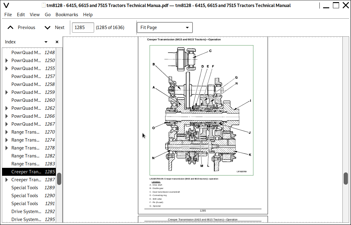
Creeper Transmission— Cross-sectional View and Operation
Creeper Transmission—Power Flow
Section 255: PowrQuad Transmissions
Group 10: Operational Check
Special Tools
PowrQuad Transmission—Operational Check
Group 15: Tests and Adjustments
PowrQuad Transmission—System Check
POWRQUAD transmission—Test Ports
PowrQuad Transmission—Checking Rate of Flow at Cooler
PowrQuad Transmission—Checking the Cooler Relief Valve
PowrQuad Transmission—System Pressure Check
PowrQuad Transmission—Checking Lube Oil Pressure
PowrQuad Transmission—Checking Cooling Oil Pressure (Forward Clutch)
PowrQuad Transmission—Checking Cooling Oil Pressure (Reverse Brake)
PowrQuad Transmission—Checking Pressure at Forward Clutch
PowrQuad Transmission—Checking Pressure at Reverse Brake
PowrQuad Transmission—Checking Pressure at Brake B1
PowrQuad Transmission—Checking Pressure at Brake B2
PowrQuad Transmission—Checking Pressure at Brake B3
PowrQuad Transmission—Checking Pressure at Clutch C4
PowrQuad Transmission—Adjusting System Pressure
PowrQuad Transmission—Test Result Table
Adjusting Gear Shift
Adjusting Forward/Reverse Cable
Adjusting Park Lock
Group 20: Operation
PowrQuad Transmissions — Summary of references
PowrQuad Transmission—Layout
PowrQuad Module—Layout
PowrQuad Module—Cross-Sectional and 3D View
PowrQuad Module—Location of Valves, Sensors and Switches
PowrQuad Module—Element Engagement Chart
PowrQuad Module—Pneumatic Pump
PowrQuad Module—Transmission Oil Pump
PowrQuad Module — Pressure-Regulating Valve and Filter Relief Valve
PowrQuad Module—Overspeed Relief Valve and Anti-Cavitation Check Valve
PowrQuad Module—Clutch Cooling Components
PowrQuad Module —Clutch Cooling Valve (Forward/Reverse)
PowrQuad Module—System 1 Oil and System 2 Oil
PowrQuad Module—Hydraulic Schematic, Mechanically Actuated PowrQuad Module
PowrQuad Module—Operation of Forward/Reverse Modulation, Mechanically Actuated PowrQuad Module
PowrQuad Module—Neutral Start Circuit, Mechanically Actuated PowrQuad Module
PowrQuad Module—Operation of Gear-to-Gear Modulation, Mechanically Actuated PowrQuad Module
Group 30: Range Box
Range Transmission (6415 and 6615 Tractors), Cross-Sectional View
Range Transmission (6415 and 6615 Tractors), Power Flows
Range Transmission, Park Lock (6415 and 6615 Tractors)
Range Transmission (7515 Tractors), — Cross-Sectional View
Creeper Transmission (6415 and 6615 Tractors)—Operation
Creeper Transmission (6415, 6615 and 7515 Tractors)—Power Flow
Section 256: Drive Systems
Group 10: Operational Check
Special Tools
Drive Systems—Operational Check
Group 15: Tests and Adjustments
Drive Systems—System Check
Checking Pressure at the Front-Wheel Drive Clutch
Checking Pressure at the Hydraulic Differential Lock
Checking Pressure at the PTO
Drive Systems—Test Result Table
Group 20: Operation
Drive Systems—Reference Summary
Front Wheel Drive Clutch (6415 and 6615 Tractors)—Cross-Sectional View
Front Wheel Drive Clutch (6415 and 6615 Tractors)—Oil Flow and Power Flow
Front Wheel Drive Clutch (6415 and 6615 Tractors)—Cooling and Lubrication
Front Wheel Drive Clutch (7515 Tractors)—Cross-Sectional View
Front Wheel Drive Clutch (7515 Tractors)—Oil Flow and Power Flow
Front Wheel Drive Clutch Disengaged (7515 Tractors)—Oil Flow
Differential (6415 and 6615 Tractors)—Cross-Sectional View
Differential (7515 Tractors)—Cross-Sectional View
Differential—Power Flows
Differential—Oil Flows
Final Drives (6415 and 6615 Tractors)—Cross-Sectional View
Final Drives (7515 Tractors)—Operation and Cross-Sectional View
PTO Options—Description
PTO Options—PTO Modulating Valve and Solenoid Valve
PTO Options—PTO brake and PTO clutch
PTO Options—Power Flows
Section 260: Steering and Brakes
Group 05: Preliminary Checks
Tests & Adjustments—Summary of References
Preliminary Checks – Steering System
Preliminary Checks – Brake System
Group 10: Operational Check
Operational Checkout (Summary of References)
Safety Information
Check Steering
Checking Brakes
Group 15: Tests and Adjustments
Tests & Adjustments—Summary of References
Special Tools
Flow Meter Kit—DQ63621
DQ61642—Pressure, Temperature, Engine Speed and Flow Gauges Kit Use KIT FKM10471 for export
Specification
Checking Steering Valve
Checking Brake System
Bleeding the Rear Brakes
Adjusting Brake Pedals and Switches
Group 20: Operation
Operation —Summary of References
Description of Steering Valves, Operation
Operation of Brake Piston, Plate and Disks
Brake released
Initial Braking
Brake Engaged
Rear Wheel Brakes, Operation
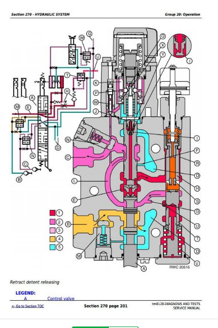
Section 270: Hydraulic System
Group 10: Operational Check
Special Tools
Checking Hydraulic System Load
Hitch Control – Operational Check
External Control of Hitch – Operational Check
Selective Control Valves – Operational Check
Group 15: Tests and Adjustments
Tests and Adjustments — Summary of References
Safety Measures for Hydraulic Checks
Warming Hydraulic System Oil
Hydraulic System — Oil Pressure Test Ports
PFC Hydraulic System Check
PFC Hydraulic System — Test Result Table
PC Hydraulic System Check
PC Hydraulic System — Test Result Table
Charge Pump — Checking Lube Oil Pressure
Charge Pump — Checking Flow Rate
Hydraulic Pump — Testing and Adjusting the System Pressure (PFC Hydraulic System)
Charge Pump — Checking Flow Rate (PFC Hydraulic System)
Hydraulic Pump — Checking the Delivery Rate (PC Hydraulic System)
Hydraulic Pump — Pressure-and-flow Regulator Check
Checking the Pressure Differential Dynamically (PFC Hydraulic System Only)
Checking the LS (Load-Sense) Pressure
Selective Control Valves — Check for Leaks at Valve Spools (PFC Hydraulic System Only)
Selective Control Valves (SCV) — Checking for Leaks in Couplers
300 and 301 Series Selective Control Valves—Adjust Detent Kickout Relief Valve Parts
Selective Control Valves—Adjusting Left Endplate With Additional LS Port For External Consumers
Selective Control Valves —Adjusting Right Endplate With Additional Ports For External Consumers
Checking Stepper Motor and Rockshaft Valve
Rockshaft Valve — Checking for Leaks
Rockshaft Valve — Checking the Pressure-Relief Valve
Rockshaft Valve — Checking Depth to Which Pressure and Discharge Valves are Screwed In
Rockshaft Valve — Checking the Position Sensor
Rockshaft—Testing and Adjusting the Draft Sensors (6415 and 6615)
Rockshaft — Testing and Adjusting the Draft Potentiometer (7515)
Adjusting the Power Beyond Valve
Group 20: Operation
PFC Hydraulic System — Summary of References
PC Hydraulic System — Summary of References
PFC Hydraulic System — Description
PFC Hydraulic System — Operation
PFC Hydraulic System — Symbolic Representation
PFC Hydraulic System — Schematic View
PFC Hydraulic System — Three-Dimensional View
PC Hydraulic System — Description
PC Hydraulic System — Operation
PC Hydraulic System — Symbolic Representation
PC Hydraulic System — Schematic View
PC Hydraulic System — Three-Dimensional View
PFC Hydraulic System — Charge Pump, Description and Operation
PFC Hydraulic System — Hydraulic Pump Description
PFC Hydraulic System — Oil Lines of Hydraulic Pump
PFC Hydraulic System — Hydraulic Pump Operation
PFC Hydraulic System — Hydraulic Pump Operating Modes
Hydraulic Pump Description'
PC Hydraulic System — Oil Lines of Hydraulic Pump
PC Hydraulic System — Hydraulic Pump Operation
Primary Hydraulic Oil Filter — Description
Hydraulic System — Description of Hydraulic Oil Filter
PC Hydraulic System — Lube Priority Valve Pump Description
PFC Hydraulic System — Description and Arrangement of Shuttle Valves
PFC Hydraulic System — Operation of Shuttle Valves
PC Hydraulic System — Description and Arrangement of Shuttle Valves
PFC Hydraulic System — Description of Main Block with Priority Valve
PFC Hydraulic System — Operation of Priority Valve in Main Block
PC Hydraulic System — Description of Main Block with Priority Valve and By-Pass Valve
PC Hydraulic System — Operation of Priority Valve and By-Pass Valve
Power Beyond Valve — Operação
Rockshaft — Description
Rockshaft — Operation of Rockshaft Control
Rockshaft — Operation of Rockshaft Valve
Rockshaft — Operation of Position Sensor
Rockshaft — Operation of Position Sensor
Rockshaft — Description of Controls
Rockshaft — Direct Drive
100 and 300 Series Selective Control Valves (Mechanically Actuated) — Description
100 Series Selective Control Valve (Mechanically Actuated) — Operation
300 Series Selective Control Valve (Mechanically Actuated) — Operation
101 and 301 Series Selective Control Valves — Description
Couplers — Description
Selective Control Valve End Plate — Summary
Section 290: Operator's Cab
Group 15: Tests and Adjustments
Operational Checkout (Summary of References)
Safety in the Workplace
Handling Refrigerant
Safety Equipment
In the Event of an Emergency
Storage of Refrigerant Containers
Refrigerant R134a
Important
Special Tools
Specification
Explanation Of Checks
Pressure Deviations
Group 20: Operation
Operation of Air Conditioning/Heating/Ventilation—Summary of References
Principle of Heat Exchange
Refrigerant R134a
Refrigerant Circuit Layout (Cab Tractors)
Refrigerant Circuit Operation
Component Description
Expansion Valve
Thermostat Switch
Heating and Ventilation
Section 299: Special Tools (Dealer-Fabricated)
Group 05: Special Tools (Dealer-Fabricated)
Special Tools (Dealer-Fabricated) — Summary
Retainer Tool
Adjustment Tool
DFRW2—Needle Valve Test Hose Assembly
DFLX10 and DFLX11—Test Harnesses
DFLX12—Special Tool for 11-bit and 29-bit CAN BUS
DFLX14—Solenoid Valve Test Harness
John Deere Tractors 6415, 6615, 7515 Diagnosis and Tests Service Technical Manual (TM8128)
![]()