
John Deere Tractors 6425, 6425HC, 7425, 7425HC, 7525, 7525HC, 6155J, 6155JH Repair Service Manual (TM608219)

John Deere Tractors 6425, 6425HC, 7425, 7425HC, 7525, 7525HC, 6155J, 6155JH Repair Service Manual (TM608219)
tm608219 - 6425, 6425HC, 7425, 7425HC, 7525, 7525HC, 6155J and 6155JH Tractors, Repair Technical Manual (March 2015) - (Mexican Version) Technical Manual.pdf
Complete Repair Service Technical Manual for John Deere 2WD or MFWD - PIN prefix P0 Tractors 6425, 6425HC, 7425, 7425HC, 7525, 7525HC, 6155J and 6155JH, with all the shop information to maintain, diagnose, repair, rebuild like professional mechanics.
John Deere 6425(HC), 7425(HC), 7525(HC),6155J(H) Tractors workshop technical manual (repair) includes:
* Numbered table of contents easy to use so that you can find the information you need fast.
* Detailed sub-steps expand on repair procedure information
* Numbered instructions guide you through every repair procedure step by step.
* Notes, cautions and warnings throughout each chapter pinpoint critical information.
* Bold figure number help you quickly match illustrations with instructions.
* Detailed illustrations, drawings and photos guide you through every procedure.
* Enlarged inset helps you identify and examine parts in detail.
PRODUCT DETAILS:
Total Pages: 1,888 pages
File Format: PDF (bookmarked, ToC, Searchable, Printable, high quality)
Language: English
MAIN SECTIONS
Foreword
Safety
Safety Precautions
General Information
Specifications
Tune-Up
Pre-Delivery Inspections
Engine
Remove And Install Engine
Fuel, Intake, Cooling and Exhaust Systems
Speed Control Linkage
Fuel System
Air Intake System
Cooling System
Exhaust System
Electrical System
Connectors
Wiring Harnesses
Charging circuit
Starter Motor Electrical Circuit
Fuses, Relays and Switches
Control Systems
Electrical Components
SyncroPlus Transmission
Removing and Installing Transmission Components
Transmission Controls
Perma Clutch II
Gear Case
Creeper Transmission
Range Transmission
PowrQuad Transmission
Component Removal and Installation
Transmission Controls
PowrQuad Module
Range Box
Drive Systems
Component Removal and Installation
Drive Shafts and Torsional Dampener
MFWD Clutch
Differential
Differential (6425)
Hydraulic Pump Drive
Final Drive
Final Drive (6425)
Final Drives on Hi-Crop Tractors
PTO
PTO (6425)
Steering and Brakes
Hydrostatic Steering
Steering Cylinders
Brake Valve
Rear Brakes
Hydraulic System
Controls
Hydraulic Pump And Charge Pump
Valves
Hydraulic Rockshaft
Selective Control Valves And Couplers
Miscellaneous
Component Removal and Installation
Main Frame
Front Axle
Hi-Crop Front Axle
Front and Rear Wheels
Swinging Drawbar
Operator's Cab
Removing and Installing Components
Air Conditioning System
Heating System
Operator's Cab
Deluxe Seat
Seat and Support
Roll-Over Protective Structure (ROPS)
Rockshaft Electronic Control Components
Special Tools (Dealer Fabricated)
Special Tools (Dealer Fabricated)
tm608219 - 6425, 6425HC, 7425, 7425HC, 7525, 7525HC, 6155J and 6155JH Tractors, Repair Technical Manual (March 2015) -: (Mexican Version)
Table of Contents
Foreword
Section 05: Safety
Group 05: Safety Precautions
Recognize Safety Information
Information - "Important"
Information - "Note"
Prevent Machine Runaway
Handle Fluids Safely—Avoid Fires
Prevent Battery Explosions
Prepare for Emergencies
Prevent Acid Burns
Avoid High-Pressure Fluids
Service Cooling System Safely
Remove Paint Before Welding or Heating
Avoid Heating Near Pressurized Fluid Lines
Work In Ventilated Area
Wear Protective Clothing
Practice Safe Maintenance
Park Machine Safely
Use Proper Lifting Equipment
Construct Dealer-Made Tools Safely
Support Machine Properly
Work in Clean Area
Illuminate Work Area Safely
Service Machines Safely
Use Proper Tools
Service Tires Safely
Safe Maintenance of Mechanical Front-Wheel Drive (MFWD) System
Do Not Look Directly Into Radar Tube
Keep ROPS Installed Properly
Replace Safety Signs
Dispose of Waste Properly
Live With Safety
Safety Measures for Electronic Control Units
Section 10: General Information
Group 05: Specifications
Specifications - Summary of References
Engine
Transmission
Hydraulic System
Overall Dimensions
Standard Tires
Loads and Weights
Electrical System
Capacities
Hydraulic Forward/Reverse
Power Take-Off
Differential Lock
Final Drive
Front Wheel Drive
Hydraulic Brakes
Park Brake
Hydraulic System with Axial Piston Pump
Hydraulic System with Gear Pump
Hydraulic Rockshaft
Handling and Storing Diesel Fuel
Diesel Fuel
Lubricity of Diesel Fuel
Diesel Engine Break-In Oil — Non-Emissions Certified and Certified Tier 1, Tier 2, Tier 3, Stage I, Stage II, and Stage III
Diesel Engine Oil
Transmission and Hydraulic Oil
Front-Wheel Drive Axle Oil
MFWD Axle Housing Oil — Hi-Crop Rear Axle
Diesel Engine Coolant
Supplemental Coolant Additives
Grease
Oil Filters
Mixing of Lubricants
Lubricant Storage
Operating in Warm Temperature Climates
Alternative and Synthetic Lubricants
Unified Inch Bolt and Screw Torque Values
Metric Bolt and Screw Torque Values
Hydraulic System Fitting Torque Values (in.)
Hydraulic System Metric Fitting Torque Values
Product Identification Number
Engine Serial Number
Transmission Serial Number
MFWD Axle Serial Number
Cab Serial Number
Group 10: Tune-Up
Tune-Up - Summary of References
Specifications
Using High-Pressure Washers
Preliminary Engine Test
Tractor Tune-Up
Removing and Cleaning the Primary Air Cleaner Element
Checking the Air Cleaner Safety Element
Installing the Primary Air Cleaner Element
Air Intake System Joint Leak Check
Checking Air Intake Hoses
Checking the Crankcase Vent Hose for Clogging
Keep Radiator Screen Clean
Cleaning Radiator
Expansion Tank Cap Check
Radiator Leak Check
Checking the Engine's Thermostat
Supply Pump Operation Check
Checking the Fuel Filter
Bleeding the Fuel System
Cleaning Water Trap
Transmission Oil - Adjusting the Oil Level Mark at the Sight-Glass
Run Engine until it is Warm and Check Engine Speeds
Cleaning the Battery, Cables and Battery Box with a Clean Cloth
Checking Neutral Start Circuit
Checking Operation of Starting Motor
Checking the Lighting Circuit
Engine Final Check
Tractor Operation Check
Fuel Injection Pump Adjustment Check
Check Speed Control Linkage Adjustment
Group 15: Pre-Delivery Inspections
Predelivery Inspection
Section 20: Engine
Group 00: Remove And Install Engine
Engine - Summary of References
Special or Essential Tools
Specifications
Engine Removal
Installing the Engine
Section 30: Fuel, Intake, Cooling and Exhaust Systems
Group 05: Speed Control Linkage
Speed Control Linkage - Summary Of References
Adjust Speed Control Linkage
Hand Throttle Lever — Exploded View
Foot Throttle, Mechanical Speed Control (OOS)
Accelerator Pedal, with Mechanical Speed Control (Cab)
Accelerator Pedal Adjustment
Group 10: Fuel System
Fuel System - Summary Of References
General Information
Removing the Fuel Tank
Installing the Fuel Tank
Replacing the fuel gauge sender
Replace Electrical Fuel Transfer Pump
Replace Fuel Filter
Replace Water Separator
Bleed Fuel System
Install Check Valve in Fuel System
Group 15: Air Intake System
Fuel, Intake, Cooling and Exhaust Systems - Air Intake System - Summary of References
General Information
Air Cleaner - Exploded View
Replace Air Filter Restriction Sensor (B02)
Group 20: Cooling System
Cooling System - Summary Of References
General Information
Specifications
Remove Radiator
Replace Fan
Remove and Install Expansion Tank
Remove And Install Thermostat
Install Radiator
Filling the Cooling System with Coolant
Relieve the Tension on the Drive Belt
Replace Drive Belt
Replace Drive Belt Tensioner
Repair Fan Bracket
Group 30: Exhaust System
Exhaust System - Summary Of References
General Information
Specifications
Exhaust System
Section 40: Electrical System
Group 05: Connectors
Connectors (Summary of References)
Special Tools
General
Using high-pressure washers
Disconnecting electrical circuits
Reconditioning Wire Ends
Installing a Terminal
WEATHER PACK Connectors
METRI PACK connector with rear terminal lock
METRI PACK connector with Front Terminal Lock
METRIC PACK Connectors
CAN BUS Terminating Resistor Connector
Electronic Control Unit Connectors
Connectors
CRIMP SNAP IN Connectors
KOSTAL Connectors
DEUTSCH Connectors
Individual terminals
Fuse and Relay Box on Tractors with Cab and Open Operator Station
Group 10: Wiring Harnesses
Wiring Harnesses — Repair — Summary of References
Disconnecting Electrical Circuits
Location of Ground Points
Remove and Install Wiring Harness W01 — Power Supply (OOS)
Removing and Installing Wiring Harness W01 — Power Supply (Cab)
Removing and Installing Wiring Harness W02 — Engine Wiring Harness (OOS Tractors)
Removing and Installing Wiring Harness W02 — Engine Wiring Harness (6425 OOS)
Removing and Installing Wiring Harness W02 — Engine Wiring Harness (Cab Tractors)
Remove and Install Wiring Harness W04 — Headlights
Removing and Installing Wiring Harness W04 — Headlights (6425 OOS)
Remove and Install Wiring Harness W10 — Shift Console
Remove and Install Wiring Harness W11 — Gear Shift and Accelerator Lever
Remove and Install Wiring Harness W13 — Clutch Sensor
Removing and Installing Wiring Harness W19 — Cab Roof
Removing and Installing Wiring Harness W26 — Fan and Air Conditioning
Remove and Install Wiring Harness W28 — Front End of Transmission (OOS)
Removing and Installing Wiring Harness W28 — Front End of Transmission (Cab Tractors)
Remove and Install Wiring Harness W30 — Rear End of Transmission (OOS)
Removing and Installing Harness W30 — Rear End of Transmission (Cab)
Remove and Install Wiring Harness W31 — 7-Pin Electrical Accessory Receptacle Connector (if installed)
Remove and Install Wiring Harness W32 - Stepper Motors (if installed)
Windshield Wiper Harness - Rear
Group 15: Charging circuit
Charging Circuit – Summary Of References
Special Tools
Specifications
Repairing the Alternator
Disconnecting Electrical Circuits
Relieve Drive Belt Tension
Remove/Install the Alternator
Pulley Removal and Installation
Group 20: Starter Motor Electrical Circuit
Starter Motor Electrical Circuit - Summary of References
Special or Essential Tools
Specifications
Repairing the Starter Motor
Disconnecting Electrical Circuits
Remove and Install Starter Motor
Group 25: Fuses, Relays and Switches
Fuses, Relays and Switches — Summary of References
Special or Essential Tools
Specifications
Disconnecting Electrical Circuits
Fuse and Relay Box - Cab Tractors
Fuse and Relay Box - Tractors with Open Operator Station
Replacing Main Fuses
Replace Main Fuses
Replace Thermo Starting Aid Fuses
Replace Starter Motor Relay
Replace Ignition Switch
Replace Brake Switch
Replace Light Switch
Replace Hazard Light Switch
Replace Turn Signal Switch
Replacing Windshield Wiper and Windshield Washer Switch
Replace MFWD Switch
Replacing Fan Switch
Replace PTO Switch
Replacing Differential Lock Switch
Rockshaft Control
Group 30: Control Systems
Control Systems — Repair — Summary of References
Disconnecting Electrical Circuits
Replace Air Filter Restriction Sensor (B02)
Check Engine Speed Sensor (B01)
Replace Engine Oil Pressure Sensor (B04)
Replace Coolant Temperature Sensor (B08)
Replace Wheel Speed Sensor (B09)
Group 40: Electrical Components
Electrical Components — Repair — Summary of References
Special Tools
Specifications
Disconnecting electrical circuits
Replacing the 7-Terminal Power Outlet Socket
Replace 3-Pin Service Connector (OOS)
Replacing Service Socket (Cab)
Removing Windshield Wiper Motor
Adjusting Front Headlights
Adjusting Cab Frame Lights
Safety Instructions for Replacing a Halogen Bulb
Section 50: SyncroPlus Transmission
Group 00: Removing and Installing Transmission Components
Special Tools
Dealer-Fabricated Special Tools
Specifications
Removing Clutch Housing
Installing Clutch Housing
Removing Gear Transmission Housing
Installing Gear Case
Group 05: Transmission Controls
Specifications
SyncroPlus Transmission Shift Units—Reconditioning (Summary of References)
Reconditioning Gear Shift Linkage
Reconditioning Range Shift Linkage
Inspecting and Adjusting Gear Shift and Range Shift Levers
Adjusting Clutch Pedal
Group 10: Perma Clutch II
Special or Essential Tools
Specifications
SyncroPlus Transmission, Perma Clutch II—Reconditioning (Summary of References)
Removing Clutch
Reconditioning Clutch
Installing Clutch
Removing Transmission Oil Pump
Reconditioning Transmission Oil Pump
Installing Transmission Oil Pump
Valves and other Hydraulic Components
Reconditioning Engagement Override Valve
Reconditioning Clutch Cooling Valve
Reconditioning Cooling Pilot Valve
Reconditioning Filter Relief Valve
Reconditioning Pressure-Regulating Valve
Reconditioning Lube Relief Valve
Reconditioning Cooler Relief Valve
Reconditioning Clutch Pedal Valve
Replacing Temperature and Pressure Sensors
Group 15: Gear Case
Special or Essential Tools
Specifications
SyncroPlus Transmission, Gear Transmission. Reconditioning (Summary of References)
Gear Transmission—Cross-Section
Removing Gear Transmission
Reconditioning Gear Transmission
Preparation for Installing the Gear Transmission
Reconditioning Shift Cover
Adjusting Shift Mechanism
Adjusting Neutral Start Switch
Group 20: Creeper Transmission
Specifications
Creeper Transmission—Reconditioning (Summary of References)
Removing Creeper Transmission
Reconditioning Creeper Transmission
Installing Creeper Transmission
Reconditioning Shift Cover
Group 25: Range Transmission
Specifications
Range Transmission—Reconditioning (Summary of References)
Range Transmission—Cross-Section
Removing Range Transmission
Reconditioning Range Transmission
Installing Range Transmission
Reconditioning Shift Cover
Section 55: PowrQuad Transmission
Group 00: Component Removal and Installation
Component Removal And Installation - Summary Of References
Special or Essential Tools
Dealer Fabricated Special Tools
Specifications
Remove PowrQuad Transmission
Install PowrQuad Transmission
Remove Range Box
Install Range Box
Group 05: Transmission Controls
PowrQuad Transmission Units - Repair - Summary of References
Specifications
Repair Gear Shift Linkage
Repair Transmission Gear Shift, Forward/Reverse and Park Brake Cable
Repair Range Shift Cable
Repair Range Shift Linkage
Forward/Reverse Lever Adjustment
Forward-Reverse Linkage Adjustment
Inspect and Adjust Gear Shift Linkage
Adjust Clutch Pedal
Group 10: PowrQuad Module
PowrQuad Transmission—Summary Of References
Special or Essential Tools
Service Equipment or Tools
Other Materials
Specifications
Transmission components
Replace Temperature and Pressure Sensors
Remove and Install Oil Filter Housing
Remove And Install Front Valve Housing
Remove And Install Front Valve Housing Valves
Remove and Install Transmission Front Cover
Remove and Install Transmission Front Cover Valves
Remove And Install Shift Valve Housing
Remove And Install Shift Valve Housing Valves
Remove Transmission Oil Pump
Repair Transmission Oil Pump
Install Transmission Oil Pump
Remove Planetary Gear Shift
Repair Planetary Gear Shift
Install Planetary Gear Shift
Remove B1 Brake Housing
Repair B1 Brake
Install B1 Brake Housing
Remove B2-B3 Brake Housing
Repair B2 Brake
Repair B3 Brake
Install B2-B3 Brake Housing
Remove C4 Clutch
Repair C4 Clutch
Install C4 Clutch
Remove Reverse Brake
Repair Reverse Brake
Install Reverse Brake
Remove Forward Clutch with Planetary Reduction (Forward/Reverse)
Repair Forward Clutch with Planetary Reduction (Forward/Reverse)
Install Forward Clutch with Planetary Reduction (Forward/Reverse)
Replace Output Shaft
Group 20: Range Box
Range Box - Repair - Summary of References
Special Tools
Repair Specifications
Remove Range Box
Range Box—Cross-Sectional View
Repair Range Box
Install Range Box
Repair Shift Cover
Replace Speed Sensor
Section 56: Drive Systems
Group 00: Component Removal and Installation
Component Removal And Installation - Summary Of References
Special or Essential Tools
Special Tools (Dealer-Fabricated)
Specifications
Remove MFWD Clutch
Install MFWD Clutch
Remove Differential Housing
Install Differential Housing
Remove Final Drive
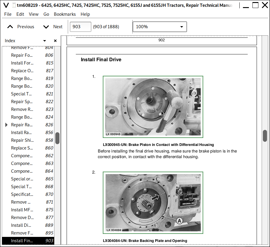
Install Final Drive
Remove PTO
Install PTO
Group 05: Drive Shafts and Torsional Dampener
Drive Shafts and Torsional Dampener - Summary of References
Specifications
Remove Drive Shaft (MFWD)
Repair Drive Shaft (MFWD)
Install Drive Shaft (MFWD)
Remove Drive Shaft (Engine)
Remove And Install Annular Cooler
Remove Torsional Dampener
Change Torsional Dampener Bearings
Install Torsion Dampener
Install Drive Shaft (Engine)
Group 10: MFWD Clutch
MFWD Clutch - Summary of References
Special or Essential Tools
Other Materials
Specifications
Disassemble MFWD Clutch
MFWD Clutch—Exploded View
Assemble MFWD Clutch
Group 15: Differential
Differential — Repair — Summary of References
Special Tools
Specifications
Remove Differential
Differential Cross-Sectional View
Disassemble Differential
Remove Differential Piston
Remove Pinion Gear
Remove Housing Cap Screw
Remove Bevel Pinions
Remove Bevel Side Gear
Disassemble
Assemble Differential
Install Pinion Gear
Install Thrust Washers
Install Bevel Side Gears
Install Shaft Retaining Cap Screw
Install Thrust Washer
Install Splined Disks
Install Piston in Differential Cover
Install Differential Cover
Install Tapered Bearings
Install Differential
Install Shim Pack
Adjust Differential Preload
Adjust Backlash
Final Assembly
Group 15A: Differential (6425)
Differential—Reconditioning (Summary of References)
Specifications
Removing Differential
Disassemble Differential
Differential — Exploded View
Assembling Differential
Installing Differential
Group 20: Hydraulic Pump Drive
Specifications
Repair Hydraulic Pump Drive
Adjust Hydraulic Pump Drive
Group 25: Final Drive
Final Drive - Summary Of References
Service Tools
Special Tools
Other Materials
Specifications
Preparation
General Repair Procedures - Final Drive
Remove Planet Pinion Carrier
Disassemble Planet Pinion Carrier
Assemble Planet Pinion Carrier
Remove Axle Housing
Disassemble and Assemble Axle Housing
Disassemble and Assemble Axle Shaft
Install Axle Housing
Install Planet Pinion Carrier And Check Rolling Drag Torque
Group 25A: Final Drive (6425)
Special or Essential Tools
Specifications
Reconditioning Final Drives
Group 25B: Final Drives on Hi-Crop Tractors
Final Drives on Hi-Crop Tractors - Summary of References
Service Tools
Specifications
General Repair Procedures—Hi-Crop Final Drive
Cross-Sectional View—Hi-Crop Final Drive
Remove Final Drive
Disassemble Final Drive
Assemble Final Drive
Install Final Drive
Group 30: PTO
PTO - Summary of References
Special Tools
Seal Installer
Service Tools
Specifications
General Repair Procedures - PTO
Clean Bearings
Repair Instructions
Repair PTO
Remove and Disassemble Countershaft
Assemble and Install Countershaft
Remove And Disassemble Output Shaft
Assemble and Install PTO Output Shaft
Remove PTO Shifter
Install PTO Shifter
Replace PTO Output Shaft Oil Seal
Remove Modulating Valve
Disassemble and Assemble Modulating Valve
Install Modulating Valve
Replace PTO Speed Sensor
Group 30A: PTO (6425)
Rear PTO Options — Summary of References
Special or Essential Tools
Special Tools Dealer-Fabricated
Other Materials
Specifications
Replacing Output Shaft Seal Ring
Replacing O-Ring on Reversible PTO
Removing PTO Clutch
Reconditioning PTO Clutch
Installing PTO clutch
Reconditioning PTO Brake
Disassembling PTO Transmission
Reconditioning Output Shaft (540/1000 RPM Reversible)
Mounting Output Shaft (540/1000 RPM)
Reconditioning Countershaft (540/1000 RPM)
Installing PTO Shift Mechanism (540/1000 RPM)
Assembling PTO transmission
Adjusting Tapered Roller Bearing of Output Shaft
Adjusting Tapered Roller Bearing of Countershaft
Installing Support and Adjusting Tapered Roller Bearings
Installing PTO Housing
Removing PTO Modulating Valve
Reconditioning PTO Modulating Valve
Installing PTO Modulating Valve
Reconditioning Solenoid
Replacing PTO Speed Sensor
Section 60: Steering and Brakes
Group 05: Hydrostatic Steering
Hydrostatic Steering - Summary Of References
Special or Essential Tools
Specifications
Preparation
Separating Fixed Column and Steering Valve ( -XXXXXX)
Remove Tilt Column and Steering Valve (XXXXXX-)
Disassemble Steering Valve
Steering Valve Exploded View
Assemble Steering Valve
Adjust Relief Valves
Repair Fixed Steering Column (-XXXXXX)
Repair Tilt Steering Column (XXXXXX-)
Group 10: Steering Cylinders
Steering Cylinders - Summary Of References
General Information
Special or Essential Tools
Specifications
Remove Steering Cylinder
Disassemble Steering Cylinder
Assemble Steering Cylinder
Install Steering Cylinder
Group 15: Brake Valve
Brake Valve - Summary Of References
Special Tools (Dealer Fabricated)
Specifications
Preparation
Remove Brake Valve
Disassemble Brake Valve
Exploded View
Assemble Brake Valve
Install Brake Valve
Adjust Brake Pedal
Final Assembly
Bleed Brakes
Group 20: Rear Brakes
Rear Brake - Summary of References
Special or Essential Tools
Specifications
Remove Rear Brakes
Repair Brakes
Check Brake Disk Wear
Install Seal on Brake Piston
Install Seal in Brake Housing
Install Brakes
Install Brake Disk
Install Thrust Plate
Check Brake Piston Return Travel and Leakage
Final Assembly
Bleed Brakes
Bleed Brakes (Cont.)
Section 70: Hydraulic System
Group 05: Controls
Controls - Summary of References
Specifications
Selective Control Valves — Removing and Installing Control Elements
Selective Control Valves — Adjusting Bowden Cable
Removing and Installing Multi-Function Lever
Adjusting Multi-Function Lever
Group 10: Hydraulic Pump And Charge Pump
Hydraulic System - Charge Pump and Hydraulic Pump, Summary of References
Other Material
Specifications
Remove and Install the Charge Pump
Charge Pump - Checking the Lube Oil Valve
Hydraulic Oil Reservoir — Restrictor
Hydraulic Pump - Removing and Installing the Pressure-and-Flow Controller
Hydraulic Pump - Reconditioning the Pressure-and-Flow Controller
Remove and Install the Hydraulic Pump
Recondition Hydraulic Pump
Group 15: Valves
Repair Valves — Summary Of References
Repair the Valves - Summary of Special Tools
Specifications
Hydraulic System — General Instructions on Safety and Repair
Repair the Priority 1 Control Block
Repair the Priority 2 Control Block
Repair the Priority 3 Control Block
Group 20: Hydraulic Rockshaft
Hydraulic System — Hydraulic Rockshaft (Summary of References)
Recondition Rockshaft - Summary of Special Tools
Other Material
Specifications
Rockshaft Valve, Removing and Installing the Stepper Motor
Remove Rockshaft Valve
Recondition the Rockshaft Valve
Install Rockshaft Valve
Rockshaft - Remove and Install the Position Sensor and Toothed Segment
Rockshaft - Remove and Install Rockshaft
Rockshaft - Remove Rockshaft Cylinders
Rockshaft — Reconditioning the Rockshaft Cylinders
Rockshaft - Install Rockshaft Cylinders
Hydraulic Rockshaft - Remove and Install Load Sensors and Draft Link Spindle Shafts
Group 25: Selective Control Valves And Couplers
Repair Selective Control Valves (SCV) and Couplers — Summary Of References
Specifications
Repair Selective Control Valves (SCV) and Couplers — General Instructions for Safety and Repair
Remove Selective Control Valves (SCV)
Repair the Selective Control Valves (M-SCVs 100)
Repair the Selective Control Valves (M-SCVs 300)
Repair the Selective Control Valves (M-SCV 450)
Install Selective Control Valves (SCV)
Section 80: Miscellaneous
Group 00: Component Removal and Installation
Component Removal And Installation - Summary Of References
Special or Essential Tools
Dealer Fabricated Special Tools
Specifications
Remove Main Frame
Install Main Frame
Remove Front Axle
Install Front Axle
Remove MFWD Axle
Install MFWD Axle
Remove Front Axle Support
Install Front Axle Support
Group 05: Main Frame
Main Frame - Summary of References
Specifications
Repair Main Frame
Group 10: Front Axle
Front Axle - Summary Of References
Special or Essential Tools
Specifications
Remove Front Axle
Repair Front Axle
Install Front Axle
Checking and Adjusting Toe-In
Group 10A: Hi-Crop Front Axle
Hi-Crop Front Axle - Summary of References
Service Tools
Specifications
Cross-Sectional View—Planetary Carrier and Wheel Hub
Remove, Recondition, And Install Planetary Carrier And Wheel Hub
Assemble And Install Planetary Carrier And Wheel Hub
Cross-Sectional View—Knuckle Spindle Assembly
Disassemble, Inspect, and Assemble Knuckle Spindle Assembly
Install MFWD Axle Into Repair Stand
Cross-Sectional View—Planetary Carrier-Wheel Hub-Knuckle Spindle-U-Joint/Axle Shaft Assembly
Remove And Install Planetary Carrier-Wheel Hub-Knuckle Spindle-U-Joint/Axle Shaft Assembly
Determine Kingpin Shim Pack
Remove Differential Housing
Cross-Sectional View—Differential Housing
Repair Differential Housing
Assemble Differential
Cross-Sectional View—Differential Drive Shaft and Input Quill
Remove And Disassemble Differential Drive Shaft
Determine Differential Drive Shaft Cone Point Shim Pack
Assemble And Install Differential Drive Shaft
Check Ring Gear Backlash And Determine Differential Case Bearing Cup Shim Pack
Adjust Ring Gear Backlash
Backlash Shim Pack Example and Worksheet
Install Differential Case Bearing Cup and Differential Housing
Disassemble And Assemble Axle Housing
Determine And Install Axle Housing Bearing Cup Shim Pack
Bearing Cup Shim Pack Procedure
Preload Shim Pack Example And Worksheet
Install Axle Housing
Cross-Sectional View—Steering Cylinder Housing Assembly
Remove And Disassemble Steering Cylinder
Cross-Sectional View—Steering Cylinder
Assemble And Install Steering Cylinder
Replace MFWD Pivot Bushing
Group 15: Front and Rear Wheels
Front and Rear Wheels - Summary Of References
Special or Essential Tools
Specifications
Remove Front and Rear Wheels
Repair Front and Rear Wheels
Install Front and Rear Wheels
Group 20: Swinging Drawbar
Swinging Drawbar - Summary of References
Specifications
Remove and Install Swinging Drawbar
Section 90: Operator's Cab
Group 00: Removing and Installing Components
Operator's Cab - Removal and Installation of Components, Summary of References
Special Tools
Repair Specifications
Tilt Operator's Cab Upward
Tilt Operator's Cab Downward
Removing Operator's Cab
Installing Operator's Cab
Group 15: Air Conditioning System
Air Conditioning System (Summary of References)
Special Tools
Specifications
Tightening Torque for Refrigerant Hoses
Safety Regulations
Handling Refrigerant
In the Event of an Emergency
Safety Equipment
Storage of Refrigerant Containers
Refrigerant R134a
Important
Other Material
Specifications
General Information
Filling the Cylinder
Cleaning the Air Conditioning System
Evacuating the System
Adding Oil to the Air Conditioning System
Charging Air Conditioning System
Leak Test
Separating Compressor
Checking Compressor Level
Disassembling the Compressor Clutch
Checking Clutch Hub Clearance
Checking the Compressor Manifold
Installing Compressor
Separating and Installing Condenser
Separating and Installing Drier
Replacing Expansion Valve
Separating and Installing Evaporator and Expansion Valve
Installing Condensation Water Drain Hoses
Layout of Condensation Water Drain Hoses
Separating and Installing Thermostat
Separating and Installing High/Low Pressure Switch
Vacuum Pump — General Information
Group 20: Heating System
Heating System (Summary of References)
Fan and Heater, Disassembling
Removing Cab Air Filter
Separating and Installing Fan
Separating and Installing Heater Regulator
Separating Heater/Evaporator Housing
Group 25: Operator's Cab
Operator's Cab (Summary of References)
Removing Cab Frame
Cab Mounting Torques
Removing and Installing Windshield
Removing and Installing Rear Window
Installing Door Lock
Adjusting Window Contact Pressure
Removing and Installing Operator's Cab Door
Removing and Installing Sun-Visor Roller
Section 95: Deluxe Seat
Group 05: Seat and Support
Seat and Support - Summary Of References
Specifications
Remove and Install Seat and Support
Group 10: Roll-Over Protective Structure (ROPS)
Roll-Over Protective Structure (ROPS) - Summary of References
Specifications
Inspect Roll-Over Protective Structure (ROPS)
Remove Roof (Canopy)
Removing and Installing Fixed Roll-Over Protective Structure (ROPS)
Remove and Install Foldable Roll-Over Protective Structure (ROPS)
Group 20: Rockshaft Electronic Control Components
Rockshaft Electronic Control Components - Summary of References
Disconnect Electrical Circuit
Service Information
Replace Control Unit (BCU)
Replace BCU Actuator
Section 99: Special Tools (Dealer Fabricated)
Group 05: Special Tools (Dealer Fabricated)
Dealer Fabricated Special Tools
Suspension Tool
DFLX13 - Holding Device
DFLX5 - Lifting Eye for Operator's Cab
DFLX10 - Holding Tool
Wooden Wedge
DFRW79 – Piston Holding Tool
DFLX22 – Socket Wrench Insert
DFLX24 - Seal Installer
DFLX25 – Driver
DFLX7 - Turning Device
DFLX8 - Thrust Pieces
DFLX6 - Bushing
DFLX27 – Driver
DFLX23 – Socket Wrench Insert
DFRW29—Final Drive Housing Adapter
DFRW30—Drive Axle Jacking Tool
Group 10: Special Tools (Available at the Dealership)
D01019AA - Single-Stage, Manually Operated Pump
D01042AA – Load-Positioning Sling
D01045AA - Bushing, Bearing and Seal Driver Set
D05007ST - Tractor Splitting Stand
FKM10427 - Crimping Pliers
FKM10461 - Wiring Harness Repair Kit
FKM10464 - Single-Acting Hydraulic Ram
FKM10469 - Crimping Pliers
JDE83 – Flywheel Turning Tool
JDG19 – Special Mounting Brackets
JDG23 – Lifting Sling
JDG359 - Electrical Repair Tool Kit
JDG364 - Extraction Tool
JDG708 - AMP Crimping Tool
JDG749 - 1.30 m (52 in.) Torque Extension
JDG750 – Swivel Socket
JDG776 - Extraction Tool
JDG777 - Extraction Tool
JDG817 - Special Wrench
JDG819 - Seal Installer
JDG1208 - Seal Installer
JDG1369 - Terminal Extraction Tool
JT02043 - Support Stand
JT02044 - Support Stand
JT03248 - Fitting
JT05723 – Medium-Duty Rear Tractor Splitting Stand
JT05724 – Medium-Duty Front Tractor Splitting Stand
JT05725 – Universal Support Stand
KJD10168 - Ring Nut Socket
KJD10169B - Special Puller
KJD10172 - Lifting Tool
KJD10173 - Special Tool
KJD10227 - Special Tool
KJD10501 - Disconnecting Tools (Kit)
OTC27489 - Handle
KJD10557 - Cab Tilting Device
![]()