
John Deere Tractors 6225, 6325, 6425, 6525 Diagnosis and Tests Service Technical Manual (TM400919)

John Deere Tractors 6225, 6325, 6425, 6525 Diagnosis and Tests Service Technical Manual (TM400919)
tm400919 - 6225 to 6525 Tractors Diagnostics Technical Manual.pdf
Complete Diagnosis & Tests Technical Manual with electrical wiring diagrams for John Deere 6225, 6325, 6425, 6525 European Tractors, with all the shop information to maintain, diagnose, rebuild like professional mechanics.
John Deere 2WD or MFWD - European Tractors 6225, 6325, 6425, 6525 workshop Diagnosis & Tests technical manual includes:
* Numbered table of contents easy to use so that you can find the information you need fast.
* Detailed sub-steps expand on repair procedure information
* Numbered instructions guide you through every repair procedure step by step.
* Troubleshooting and electrical service procedures are combined with detailed wiring diagrams for ease of use.
* Notes, cautions and warnings throughout each chapter pinpoint critical information.
* Bold figure number help you quickly match illustrations with instructions.
* Detailed illustrations, drawings and photos guide you through every procedure.
* Enlarged inset helps you identify and examine parts in detail.
PRODUCT DETAILS:
Total Pages: 1,672 pages
File Format: PDF (bookmarked, ToC, Searchable, Printable, high quality)
Language: English
MAIN SECTIONS
Foreword
General Information
Safety Information
General References
Diagnostic Trouble Codes
ECU Control Unit
Observable Symptoms
Electrical System
SyncroPlus Transmission
PowrReverser Transmission
Drive Systems
Steering and Brakes
Hydraulic System
System Diagnostics
Electronics
Engine
General Information
Operational Checks
Tests and Adjustments
Fuel, Air Intake and Cooling Systems
Tests and Adjustments
Fuel System
Air Intake System
Cooling System
Cold-Weather Starting Aids
Electrical System
Starting Motor and Charging Circuit
Fuel Preheater
Electrical Starting Aid
Instrument Unit
Horn
Lights
Worklights
3-Terminal Socket (ECE)
Connector for Accessories
Hazard Warning and Turn Signal Lights
Brake Lights
Differential Lock
Front-Wheel Drive
Service Socket
7-Terminal Socket (ECE)
Level 16 ECU Control Unit (Electronic Engine Control) for 2-Valve Engine with HPCR
Component Information - Connectors
Component Information - Wiring Harnesses
Component Information - Electrical Parts/Components
Component Information - Ground Connections
Component Information - CAN BUS System
Electronic Control Units
Operation and General Information on Diagnostics
Data BUS Systems
ECU Control Unit
SyncroPlus Transmission
Operational Checks
Tests and Adjustments
Theory of Operation
PowrReverser Transmission
Operational Checks
Tests and Adjustments
Theory of Operation
Drive Systems
Operational Checks
Tests and Adjustments
Front-Wheel Drive Clutch
Differential
Final Drives
Rear PTO Options
Steering and Brakes
Introductory Checks
Operational Checks
Tests and Adjustments
Hydrostatic Steering
Brake Valve
Rear Wheel Brakes
Handbrake
Hydraulic Trailer Brake
Hydraulic System
Operational Checks
Tests and Adjustments
Theory of Operation
Oil Filter and Hydraulic Pump
Hitch
Selective Control Valves
Special Tools
Special Tools (Dealer-Fabricated)
Special Tools (Available as Spare Parts)
tm400919 - 6225 to 6525TractorsDiagnostics
Table of Contents
Foreword
Section 210: General Information
Group 05: Safety Information
General Information - Safety - Summary of References
Recognize Safety Information
”Important” Information
”Note” Information
Prevent Machine Runaway
Handle Fluids Safely—Avoid Fires
Prevent Battery Explosions
Prepare for Emergencies
Prevent Acid Burns
Avoid High-Pressure Fluids
Service Cooling System Safely
Remove Paint Before Welding or Heating
Avoid Heating Near Pressurized Fluid Lines
Work In Ventilated Area
Wear Protective Clothing
Practice Safe Maintenance
Park Machine Safely
Use Proper Lifting Equipment
Construct Dealer-Made Tools Safely
Support Machine Properly
Work in Clean Area
Illuminate Work Area Safely
Service Machines Safely
Use Proper Tools
Service Tires Safely
Service Front-Wheel Drive Tractor Safely
Safety Information - Air Brake System
Avoid Eye Contact With Radar
Keep ROPS Installed Properly
Replace Safety Signs
Replace Safety Signs
Dispose of Waste Properly
Live With Safety
Safety Measures on Electronic Control Units
Servicing Electronic Control Units
Welding Near Electronic Control Units
Keep Electronic Control Unit Connectors Clean
Safety Instructions for Replacing a Halogen Bulb
Safety Instructions for Replacing Xenon (HID) Bulbs and Ballast Units
Group 10: General References
General Information - General References, Summary of References
General Information - Transmission and Hydraulic System, Introductory Checks
General Information - Inch Bolt and Cap Screws, Torque Values
General Information - Metric Bolt and Cap Screws, Torque Values
General Information - Hydraulic System Inch Fittings, Torque Values
General Information - Hydraulic System Metric Fittings, Torque Values
General Information - Electrical System, Component Identification Table
General Information - Electrical System, How to Read a Diagnostic Schematic
General Information - Electrical System, Lead Numbers and Color Codes
General Information - Electrical System, Symbols in Schematic, Wiring and Harness Diagrams
General Information - Electrical System, Approach to Tabular Diagnostic Procedures
General Information - Electrical System, Troubleshooting Unsolved Problems
General Information - Electrical System, Worksheet for Circuit/Harness Test
General Information - Electrical System, Visual Check
General Information - Electrical System, Electrical Circuit Malfunctions
General Information - Electrical System, Seven-Step Test Procedure
General Information - Hydraulic System, Symbols in Circuit Diagrams
General Information - Check the Oil Sight-Glass (when the Tire Combination has been Changed)
General Information - Country Version
Section 211: Diagnostic Trouble Codes
Group ECU: ECU Control Unit
ECU 000029.03 - B96 - Hand Throttle Potentiometer, Voltage Too High
ECU 000029.04 - B96 - Hand Throttle Potentiometer, Voltage Too Low
ECU 000091.03 - B79 - Accelerator Pedal Potentiometer, Voltage Too High
ECU 000091.04 - B79 - Accelerator Pedal Potentiometer, Voltage Too Low
ECU 000097.03 - Water-in-Fuel Sensor Signal Voltage Too High
ECU 000097.04 - Water-in-Fuel Sensor Signal Voltage Too Low
ECU 000097.16 - Water In Fuel Detected
ECU 000105.00 - Intake Air Temperature Extremely High
ECU 000105.03 - Intake Air Temperature Sensor Input Voltage Too High
ECU 000105.04 - Intake Air Temperature Sensor Input Voltage Too Low
ECU 000105.15 - Intake Air Temperature Slightly Too High
ECU 000105.16 - Intake Air Temperature Slightly High
ECU 000108.02 - Barometric Air Pressure Invalid
ECU 000110.00 - Engine Coolant Temperature Extremely High
ECU 000110.03 - Engine Coolant Temperature Sensor Input Voltage Too High
ECU 000110.04 - Engine Coolant Temperature Sensor Input Voltage Too Low
ECU 000110.15 - Engine Coolant Temperature Slightly High
ECU 000110.16 - Engine Coolant Temperature Moderately High
ECU 000157.03 - Fuel Rail Pressure Sensor Input Voltage Too High
ECU 000157.04 - Fuel Rail Pressure Sensor Input Voltage Too Low
ECU 000157.10 - Fuel Rail Pressure Loss Detected
ECU 000157.17 - Fuel Rail Pressure Not Developed
ECU 000158.17 - ECU Power Down Error
ECU 000174.00 - Fuel Temperature Extremely High
ECU 000174.03 - Fuel Temperature Sensor Input Voltage Too High
ECU 000174.04 - Fuel Temperature Sensor Input Voltage Too Low
ECU 000174.16 - Fuel Temperature Moderately High
ECU 000189.00 - Engine Speed Derate
ECU 000190.00 - Engine Overspeed Extreme
ECU 000190.16 - Engine Overspeed Moderate
ECU 000611.03 - Electronic Injector Wiring Shorted To Power Source
ECU 000611.04 - Electronic Injector Wiring Shorted To Ground
ECU 000627.01 - High Resistance In All Injector Circuits
ECU 000629.12 - ECU Error (EEPROM)
ECU 000629.13 - ECU Error
ECU 000636.02 - Pump Position Sensor Input Noise
ECU 000636.05 - Pump Position Sensor Current Too Low
ECU 000636.06 - Pump Position Sensor Current Too High
ECU 000636.08 - Pump Position Sensor Input Missing
ECU 000636.10 - Pump Position Sensor Input Pattern Error
ECU 000637.02 - Crank Sensor Input Noise
ECU 000637.05 - Crank Sensor Current Too Low
ECU 000637.06 - Crank Sensor Current Too High
ECU 000637.07 - Crank Position/Pump Position Timing Moderately Out of Sync
ECU 000637.08 - Crank Sensor Signal Input Missing
ECU 000637.10 - Crank Sensor Input Pattern Error
ECU 000651.02 - Cylinder No.1 Electronic Injector Part Number Invalid
ECU 000651.05 - Cylinder No.1 Electronic Injector Circuit Open
ECU 000651.06 - Cylinder No.1 Electronic Injector Circuit Shorted
ECU 000651.13 - Calibration Fault, Cylinder No.1 Injector
ECU 000652.02 - Cylinder No.2 Electronic Injector Part Number Invalid
ECU 000652.05 - Cylinder No.2 Electronic Injector Circuit Open
ECU 000652.06 - Cylinder No.2 Electronic Injector Circuit Shorted
ECU 000652.13 - Calibration Fault, Cylinder No.2 Injector
ECU 000653.02 - Cylinder No.3 Electronic Injector Part Number Invalid
ECU 000653.05 - Cylinder No.3 Electronic Injector Circuit Open
ECU 000653.06 - Cylinder No.3 Electronic Injector Circuit Shorted
ECU 000653.13 - Calibration Fault, Cylinder No.3 Injector
ECU 000654.02 - Cylinder No.4 Electronic Injector Part Number Invalid
ECU 000654.05 - Cylinder No.4 Electronic Injector Circuit Open
ECU 000654.06 - Cylinder No.4 Electronic Injector Circuit Shorted
ECU 000654.13 - Calibration Fault, Cylinder No.4 Injector
ECU 000655.02 - Cylinder No.5 Electronic Injector Part Number Invalid
ECU 000655.05 - Cylinder No.5 Electronic Injector Circuit Open
ECU 000655.06 - Cylinder No.5 Electronic Injector Circuit Shorted
ECU 000655.13 - Calibration Fault, Cylinder No.5 Injector
ECU 000656.02 - Cylinder No.6 Electronic Injector Part Number Invalid
ECU 000656.05 - Cylinder No.6 Electronic Injector Circuit Open
ECU 000656.06 - Cylinder No.6 Electronic Injector Circuit Shorted
ECU 000656.13 - Calibration Fault, Cylinder No.6 Injector
ECU 000676.03 - Glow Plug Relay Voltage Too High
ECU 000676.05 - Glow Plug Relay Voltage Too Low
ECU 001347.03 - Suction Control Valve Current Too High
ECU 001347.05 - Suction Control Valve Current Mismatch
ECU 001347.07 - Fuel Rail Pressure Control Error
ECU 001569.31 - Fuel Derate
ECU 003509.03 - Sensor Supply Voltage 1 Too High
ECU 003509.04 - Sensor Supply Voltage 1 Too Low
ECU 003510.03 - Sensor Supply Voltage 2 Too High
ECU 003510.04 - Sensor Supply Voltage 2 Too Low
ECU 003511.03 - Sensor Supply Voltage 3 Too High
ECU 003511.04 - Sensor Supply Voltage 3 Too Low
Section 212: Observable Symptoms
Group 40: Electrical System
Control Unit not Displayed
Problems with the CAN-BUS Connection to Service ADVISOR
Problems While Reprogramming Control Units
Charging Circuit Problem
Problem with the Starting Motor
Problem with the Battery
Problem with Fuel Preheater Element
Problem with the Fuel Pump
Problem with Heating Element of Electrical Starting Aid (2-Valve Engine with HPCR)
Problem with the Instrument Unit
Problem with the Horn
Problem with the Parking Lights
Problem with the Low-Beam Headlights
Problem with the High-Beam Headlights
Problem with the Front Corner Worklights
Problem with Worklights on Rear Fenders
Problem with the 3-Terminal Power Outlet Socket
Problem with the 2-Pin Plug of Front Loader
Problem with the Hazard Warning Lights
Problem with the Turn Signals
Problem with Brake Lights
Problem with the Differential Lock
Problem with the Front-Wheel Drive
Problem with the 7-Terminal Power Outlet Socket
Group 50: SyncroPlus Transmission
Problem with SyncroPlus Transmission
Group 51: PowrReverser Transmission
Problem with PowrReverser Transmission
Group 56: Drive Systems
Problem with the rear PTO
Problem with the Front-Wheel Drive
Problem with the Differential Lock
Group 60: Steering and Brakes
Problem with the Brakes
Problem with the Steering
Problem with the Handbrake
Group 70: Hydraulic System
Hitch lowers too fast
Hitch: Incorrect reaction of position or draft control
Hitch: Lift arms rise too slowly or erratically
Section 213: System Diagnostics
Group 45: Electronics
Check for Vehicle CAN BUS
Section 220: Engine
Group 05: General Information
Information on Engine
Group 10: Operational Checks
Engine - Safety Measures
Engine - Preliminary Engine Tests
Group 15: Tests and Adjustments
Engine - Tests and Adjustments, Summary of References
Engine - Measure PTO Power Output
Engine - Engine Tests with Service ADVISOR
Section 230: Fuel, Air Intake and Cooling Systems
Group 15: Tests and Adjustments
Fuel, Air Intake and Cooling Systems - Tests and Adjustments, Summary of References
Fuel, Air Intake and Cooling Systems - General Information
Fuel, Air Intake and Cooling Systems - Explanation of Checks
Fuel, Air Intake and Cooling Systems - Safety Measures
Fuel, Air Intake and Cooling Systems - Special Tools, Summary of References
Fuel, Air Intake and Cooling Systems - Specifications
Air Intake System - System Check
Cooling System - Fill/Bleed the System
Cooling System - Leak Test
Cooling System - Test Thermostat Opening Temperature
Cooling System - Flow Testing in the Low-Temperature Circuit
Cooling System - Check the Viscous Fan Drive
Fuel System - Check the Fuel Transfer Pump
Group 20A: Fuel System
Fuel System - Theory of Operation, Summary of References
Fuel System - Theory of Operation
Fuel System - Fuel Cooler, Component Information
Fuel System - Fuel Transfer Pump, Component Information
Group 20B: Air Intake System
Air Intake System - Theory of Operation, Summary of References
Air Intake System - Theory of Operation
Group 20C: Cooling System
Cooling System - Summary of References
Cooling System - Coolant Circuit, Description
Cooling System - Radiator Description, Component Information
Cooling System - Intercooler, Component Information
Cooling System - Transmission Oil Cooler, Component Information
Cooling System - Viscous Fan Drive, Theory of Operation
Cooling System - Automatic Drive Belt Tensioner, Theory of Operation
Group 20D: Cold-Weather Starting Aids
Cold-Weather Starting Aids - Summary of References
Cold-Weather Starting Aids - General Information
Cold-Weather Starting Aids - Coolant Heater - Component Information
Cold-Weather Starting Aids - Transmission Oil Heater - Component Information
Cold-Weather Starting Aids - Charge Pump Preheater - Component Information
Section 240: Electrical System
Group SE01: Starting Motor and Charging Circuit
SE01 - Starting Motor and Charging Circuit - Summary of References
Diagnostic Schematic, SE01 - Starting Motor and Charging Circuit
Group SE01A: Fuel Preheater
SE01A - Fuel Preheater - Summary of References
Diagnostic Schematic, SE01A - Fuel Preheater
Group SE01C: Electrical Starting Aid
SE01C - Electrical Starting Aid - Summary of References
Diagnostic Schematic, SE01C - Electrical Starting Aid
Group SE02: Instrument Unit
SE02 - Instrument Unit - Summary of References
Diagnostic Schematic, SE02 - Instrument Unit
Group SE03: Horn
SE03 - Horn - Summary of References
Diagnostic Schematic, SE03 - Horn
Group SE06: Lights
SE06 - Lights - Summary of References
Diagnostic Schematic, SE06 - Lights
Group SE07: Worklights
SE07 - Worklights - Summary of References
Diagnostic Schematic, SE07 - Worklights
Group SE14: 3-Terminal Socket (ECE)
SE14 - 3-Terminal Socket (ECE) - Summary of References
Diagnostic Schematic, SE14 - 3-Terminal Socket (ECE)
Group SE14A: Connector for Accessories
SE14A - Plug for Accessories - Summary of References
Diagnostic Schematic, SE14A - Plug for Accessories
Group SE16A: Hazard Warning and Turn Signal Lights
SE16A - Hazard Warning and Turn Signal Lights - Summary of References
Diagnostic Schematic, SE16A - Hazard Warning and Turn Signal Lights
Group SE16C: Brake Lights
SE16C - Brake Lights - Summary of References
Diagnostic Schematic, SE16C - Brake Lights
Group SE16D: Differential Lock
SE16D - Differential Lock - Summary of References
Diagnostic Schematic, SE16D - Differential Lock
Group SE16E: Front-Wheel Drive
SE16E - Front-Wheel Drive - Summary of References
Diagnostic Schematic, SE16E - Front-Wheel Drive
Group SE17: Service Socket
SE17 - Service Socket - Summary of References
Diagnostic Schematic, SE17 - Service Socket
Group SE17A: 7-Terminal Socket (ECE)
SE17A - 7-Terminal Socket (ECE) - Summary of References
Diagnostic Schematic, SE17A - 7-Terminal Socket (ECE)
Group SE23: Level 16 ECU Control Unit (Electronic Engine Control) for 2-Valve Engine with HPCR
SE23 - Level 16 ECU (Electronic Engine Control) for 2-Valve Engine with HPCR - Summary of References
Diagnostic Schematic, SE23 - Level 16 ECU Control Unit (Electronic Engine Control)
B79 - Accelerator Pedal Potentiometer, Circuit/Harness Test
B96 - Hand Throttle Potentiometer, Circuit/Harness Test
K02PLB/01 - Relay for Electrical Starting Aid, Circuit/Harness Test
Group 105: Component Information - Connectors
F01PLB - Fuses
F02PLB - Fuses
F02 - Fuses (Open Operator's Station)
F05 - Fuses (Open Operator's Station)
G02-1 - Terminal with Ring for Alternator
K01PLB - Starting Motor Relay
K02PLB - Relay for Electrical Starting Aid
K03PLB - Relay
K01 - Relays (Open Operator's Station)
K03 - Relays (Open Operator's Station)
K04 - Relays (Open Operator's Station)
K05 - Relays (Open Operator's Station)
K20-1 - Plug of Turn-Signal Relay
M01-50 - Terminal for Starting Motor
S01F - Plug of Main (Key) Switch
S01F-1 - Terminal for Main (Key) Switch
S04F - Plug of Horn Switch
S08F - Plug of Turn-Signal Switch
S10F - Plug of High-/Low-Beam Switch
X05F - Plug of 7-Terminal Power Outlet Socket (ECE)
X37F - Plug for Front Loader
X66F - Plug of Horn
X67F - Plug of Right Headlight
X68F - Plug of Left Headlight
X69F-1 - Plug of Left Front Corner Worklight
X69F-2 - Plug of Right Front Corner Worklight
X70F - Plug of Sensor for Air Cleaner Restriction Warning Light
X77F - Plug of Sensor for Coolant Temperature Gauge
X78F - Plug of Engine Oil Pressure Switch
X79F - Plug of Heating Element of Fuel Preheater
X80M - Plug of Transmission Oil Filter Pressure Switch
X81F - Terminal of Low-Temperature Switch (Transmission Oil)
X82F - Terminal of High-Temperature Switch (Transmission Oil)
X83M - Plug of Transmission Oil Pressure Switch
X87F - Plug of Differential Lock Solenoid Valve
X88F-3 - Plug of Wheel Speed Sensor
X91F - Plug of Front-Wheel Drive Solenoid Valve
X93F - Plug of Neutral-Start Switch
X112F-1 - Plug of Worklight on Rear of Left Fender
X112F-2 - Plug of Worklight on Rear of Right Fender
X113F - Plug for License Plate Light
X122F - Plug of Differential Lock Switch
X234F - Connecting Point between Harnesses W07 and W21 (ECE)
X234M - Connecting Point between Harnesses W21 and W07
X239F - Connecting Point between Harnesses W21 and W04
X261F - Plug of Coolant Temperature Sensor
X286F - Connecting Point between Harnesses W21 and W61
X286M - Connecting Point between Harnesses W61 and W21
X287F - Connecting Point between Harnesses W21 and W63
X287M - Connecting Point between Harnesses W63 and W21
X301F - Plug of Intake Air Temperature Sensor
X305F - Plug of Radiator Ground Connection
X315F - Plug of Handbrake Monitor Switch
X321F - Plug of Hand Throttle Potentiometer
X324F - Plug of Sensor Unit for Brake Pedal
X356F - Plug of Crankshaft Speed Sensor
X359F - Plug of Camshaft Speed Sensor (Pump Position)
X371F - Plug of Accelerator Pedal Potentiometer
X392F-L - Plug for Clearance, Tail, Brake and Turn Signal Lights (Left)
X392F-R - Plug for Clearance, Tail, Brake and Turn Signal Lights (Right)
X402M - Plug of Switch for Front Corner Worklights
X406F - Plug of Light Switch
X411F - Connecting Point between Harnesses W51 and W11
X411M - Connecting Point between Harnesses W11 and W51
X433M - Plug of Switch for Worklights on Rear of Fender
X473F - Connecting Point between Harnesses W01 and W21
X473M - Connecting Point between Harnesses W21 and W01
X516M - Plug of Hazard Warning Light Switch
X547F - Connecting Point between Harnesses W51 and W01
X547M - Connecting Point between Harnesses W01 and W51
X550F - Plug of Fuel Temperature Sensor
X566F - Plug of Suction Control Valve
X567F - Plug of Water-in-Fuel Sensor
X568F - Plug of Injection Valves (4-Cylinder, 2-Valve Engine with HPCR)
X571M - Service Socket (CAN BUS)
X579F - Plug of Preheater Indicator Light
X617F - Plug of Instrument Unit
X618F - Plug of Instrument Unit
X625F - Plug of Rail Pressure Sensor
X780F - Connecting Point between Harnesses W22 and W21
X780M - Connecting Point between Harnesses W21 and W22
X782F - Connecting Point between Harnesses W51 and W21
X782M - Connecting Point between Harnesses W21 and W51
X803F - Plug of Fuel Level Sensor
X804 - Plug of Fuel Pump
X844F-1 - Plug of ECU Control Unit (Level 16) (4-Cylinder Engine)
X844F-1 - Plug of ECU Control Unit (Level 16) (6-Cylinder Engine)
X844F-2 - Plug of ECU Control Unit (Level 16)
X845F - Plug of Injection Valves (6-Cylinder, 2-Valve Engine with HPCR)
X858 - Terminal with Ring for Battery Connection
X861 - Terminal with Ring for Alternator
X885 - Terminal with Ring, for Heater Element (Electrical Starting Aid)
X920M - Plug of Front-Wheel Drive Switch
XGND1 - Ground Point
XGND1-1 - Collective Ground Point for XGND1
XGND2 - Ground Point
XGND2-1 - Collective Ground Point for XGND2
XGND4A - Ground Point
XGND4-1 - Collective Ground Point for XGND4
XGND9 - Ground Point
Group 110: Component Information - Wiring Harnesses
Component Information - Wiring Harnesses - Summary of References
General Information
W01/7: Front Fuse Box Wiring Harness
W07/1: Wiring Harness for 7-Terminal Socket (ECE)
W11/5: Hood Wiring Harness
W21/5: Wiring Harness for Open Operator's Station
W22/5: Wiring Harness for Cowl
W51/7: Wiring Harness for 4-Cylinder Engine (2V-HPCR, Level 16)
W51/8: Wiring Harness for 6-Cylinder Engine (2V-HPCR, Level 16)
W61/16: Front Transmission Wiring Harness
W63/7: Rear Transmission Wiring Harness
Group 115: Component Information - Electrical Parts/Components
Component Information - Electrical Parts/Components - Summary of References
1-/3-amp Diode
10-/20-amp Relay
20-/40-amp Relay
70-amp Relay
70-/100-amp Relay
A86 - ECU Control Unit (Level 16)
B02 - Sensor for Air Cleaner Restriction
B04 - Engine Oil Pressure Switch
B05 - Handbrake Monitor Switch
B07 - Transmission Oil Filter Pressure Switch
B08 - Sensor for Coolant Temperature Gauge
B29 - Switch, Low Transmission Oil Temperature
B30 - Switch, High Transmission Oil Temperature
B31 - Transmission Oil Pressure Switch
B35 - Wheel Speed Sensor on Tractors without Creeper
B36 - Neutral Start Switch
B56 - Coolant Temperature Sensor
B59 - Intake Air Temperature Sensor
B72 - Crankshaft Speed Sensor
B74 - Camshaft Speed Sensor (Pump Position)
B79 - Accelerator Pedal Potentiometer
B96 - Hand Throttle Potentiometer
B112 - Brake Pedal Sensor Unit
B114 - Fuel Temperature Sensor
B121 - Water-in-Fuel Sensor
B137 - Rail Pressure Sensor
B176 - Fuel Level Sensor
E01 - R.H. Headlight
E02 - L.H. Headlight
E03 - L.H. Clearance Light (ECE)
E04 - R.H. Clearance Light (ECE)
E09-L - Front Corner Worklight (Left)
E09-R - Front Corner Worklight (Right)
E13 - L.H. Tail Light
E14 - R.H. Tail Light
E15-L - Worklight on Rear of Left Fender
E15-R - Worklight on Rear of Right Fender
E21 - License Plate Light (ECE)
F01PLB to F02PLB - Fuses (Fuse Box in Engine Compartment)
F02 to F05 - Fuses (Open Operator's Station)
G01 - Battery
G02 - Alternator
H01 - Horn
H32 - Left Brake Light
H33 - Right Brake Light
H34 - Front Left Turn Signal Light (ECE)
H35 - Rear Left Turn Signal Light
H42 - Front Right Turn Signal Light (ECE)
H43 - Rear Right Turn Signal Light
H77 - Indicator Light for Heater Element (Electrical Starting Aid)
K01PLB to K03PLB - Relays (Fuse Box in Engine Compartment)
K01 to K05 - Relays (Open Operator's Station)
K20 - Turn-Signal Relay
M01 - Starting Motor
M31 - Fuel Pump
P21 - Instrument Unit
R02 - Heating Element of Fuel Preheater
R15 - Heating Element of Electrical Starting Aid (2-Valve Engine with HPCR)
R19 - CAN BUS Terminating Resistor
S01 - Main (Key) Switch
S04 - Horn Switch
S08 - Turn Signal Lever
S09 - Light Switch
S10 - High Beam Switch
S22 - Differential Lock Switch
S59 - Switch for Front Corner Worklights
S92 - Switch for Worklight on Rear Fender
S107 - Hazard Warning Light Switch
S161 - Front-Wheel Drive Switch
X05 - 7-Terminal Power Outlet Socket (ECE) at Rear
X571M - Service Socket (CAN BUS)
Y03 - Solenoid Valve for Front-Wheel Drive
Y05 - Solenoid Valve for Differential Lock
Y44 - Suction Control Valve
Y82 - Injector for Cylinder 1 (4-Cylinder Engines)
Y83 - Injector for Cylinder 2 (4-Cylinder Engines)
Y84 - Injector for Cylinder 3 (4-Cylinder Engines)
Y85 - Injector for Cylinder 4 (4-Cylinder Engines)
Y86 - Injector for Cylinder 1 (6-Cylinder Engines)
Y87 - Injector for Cylinder 2 (6-Cylinder Engines)
Y88 - Injector for Cylinder 3 (6-Cylinder Engines)
Y89 - Injector for Cylinder 4 (6-Cylinder Engines)
Y90 - Injection Valve for Cylinder 5 (6-Cylinder Engines)
Y91 - Injector for Cylinder 6 (6-Cylinder Engines)
Group 120: Component Information - Ground Connections
Component Information - Ground Connections - Summary of References
XGND1
XGND2
XGND4
XGND9
Group 125: Component Information - CAN BUS System
Component Information - CAN BUS System - Summary of References
CAN Bus System
Section 245: Electronic Control Units
Group 05: Operation and General Information on Diagnostics
Operation and General Information on Diagnostics - Summary of References
Operation and General Information on Diagnostics - Special Tools
Operation and General Information on Diagnostics - Abbreviations for Control Units
Operation and General Information on Diagnostics - Operation and Entering the Program Mode using the Performance Monitor
Operation and General Information on Diagnostics - Accessing Addresses and Diagnostic Trouble Codes
Operation and General Information on Diagnostics - Approved Software for Control Units
Operation and General Information on Diagnostics - Locations and Allocations of Control Units
Group 20: Data BUS Systems
Data BUS Systems - Summary of References
Data BUS Systems - CAN BUS Systems
Data BUS Systems - CAN BUS Systems on Engines with Level 16 Control Unit (2-Valve HPCR Fuel System)
Data BUS Systems - CAN BUS Systems, Plug Layout
Group ECU: ECU Control Unit
ECU - Summary of References
ECU - Summary of Addresses (Level 16 ECU for 2-Valve Engine with HPCR)
ECU - Calibration and Input Addresses (Level 16 ECU for 2-Valve Engine with HPCR)
ECU - Theory of Operation (Level 16 ECU for 2-Valve Engine with HPCR)
Section 250: SyncroPlus Transmission
Group 10: Operational Checks
SyncroPlus Transmission - Operational Check-Out, Summary of References
SyncroPlus Transmission - Operational Check-Out
Group 15: Tests and Adjustments
SyncroPlus Transmission - Tests and Adjustments, Summary of References
SyncroPlus Transmission - Special Tools, Summary of References
SyncroPlus Transmission - System Check
SyncroPlus Transmission - Check the System Pressure
SyncroPlus Transmission - Adjust the System Pressure
SyncroPlus Transmission - Check the Components Dependent On System Pressure
SyncroPlus Transmission - Check the Filter Bypass Valve
SyncroPlus Transmission - Check the Engagement Override Valve and the Clutch Pedal Valve
SyncroPlus Transmission - Check the Modulation of the Clutch Pedal Valve
SyncroPlus Transmission - Check the Lube Oil Pressure
SyncroPlus Transmission - Check the Cooling System
SyncroPlus Transmission - Check the Flow Rate
SyncroPlus Transmission - Check the Cooler Relief Valve
SyncroPlus Transmission - Check the Transmission Oil Filter
SyncroPlus Transmission - Layout of Test Ports and Sensors
SyncroPlus Transmission - Check and Adjust the Shift Mechanism/Linkage
SyncroPlus Transmission - Check and Adjust the Park Lock
SyncroPlus Transmission - Adjust the Clutch Pedal
Group 20: Theory of Operation
SyncroPlus Transmission - Theory of Operation, Summary of References
SyncroPlus Transmission - Layout
SyncroPlus Transmission - Lubrication System
SyncroPlus Transmission - Shift Operation
SyncroPlus Transmission - Synchronization
SyncroPlus Transmission - Operation of Transmission Oil Circuit (including Diagram)
SyncroPlus Transmission - Transmission Oil Pump
SyncroPlus Transmission - Perma Clutch II Module, Exploded View
SyncroPlus Transmission - Perma Clutch II Module, Layout
SyncroPlus Transmission - Perma Clutch II Module, Power Flow
SyncroPlus Transmission - Perma Clutch II Module, Hydraulic Diagram
SyncroPlus Transmission - Perma Clutch II Module, Description of Various Valves and Components
SyncroPlus Transmission - Perma Clutch II Module, Pressure Regulating and Filter Bypass Valves
SyncroPlus Transmission - Perma Clutch II Module, Clutch Pedal Valve and Engagement Override Valve
SyncroPlus Transmission - Perma Clutch II Module, Cooling
SyncroPlus Transmission - Gear Transmission, Layout
SyncroPlus Transmission - Gear Transmission, Power Flow
SyncroPlus Transmission - Gear Transmission, Neutral Start Switch
SyncroPlus Transmission - Range Transmission, Layout
SyncroPlus Transmission - Range Transmission, Power Flow
SyncroPlus Transmission - Range Transmission, Park Lock
Section 251: PowrReverser Transmission
Group 10: Operational Checks
PowrReverser Transmission - Operational Check-Out, Summary of References
PowrReverser Transmission - Operational Check-Out
Group 15: Tests and Adjustments
PowrReverser Transmission - Tests and Adjustments, Summary of References
PowrReverser Transmission - Special Tools, Summary of References
PowrReverser Transmission - System Check
PowrReverser Transmission - Check System Pressure
PowrReverser Transmission - Adjust the System Pressure
PowrReverser Transmission - Check the Components Dependent On System Pressure
PowrReverser Transmission - Check the Filter Bypass Valve
PowrReverser Transmission - Check the Engagement Override Valve and the Clutch Pedal Valve
PowrReverser Transmission - Check the Disk Clutch and the Disk Brake
PowrReverser Transmission - Check Lube Oil Pressure
PowrReverser Transmission - Check the Cooling System
PowrReverser Transmission - Check the Flow Rate
PowrReverser Transmission - Check the Cooler Relief Valve
PowrReverser Transmission - Check the Transmission Oil Filter
PowrReverser Transmission - Adjust the Modulation Time
PowrReverser Transmission - Layout of Test Ports and Sensors
PowrReverser Transmission - Check and Adjust the Shift Mechanism/Linkage
PowrReverser Transmission - Adjust the Park Lock
PowrReverser Transmission - Adjust the Reverse Drive Linkage with Mechanically Actuated PowrReverser Module
PowrReverser Transmission - Adjust the Reverse Drive Lever with Mechanically Actuated PowrReverser Module
PowrReverser Transmission - Adjust the Clutch Pedal
Group 20: Theory of Operation
PowrReverser Transmission - Theory of Operation, Summary of References
PowrReverser Transmission - Layout
PowrReverser Transmission - Lubrication System
PowrReverser Transmission - Shift Operation
PowrReverser Transmission - Synchronization
PowrReverser Transmission - Operation of Transmission Oil Circuit (including Diagram)
PowrReverser Transmission - Transmission Oil Pump
PowrReverser Transmission - PowrReverser Module, Sectional View
PowrReverser Transmission - PowrReverser Module, Components
PowrReverser Transmission - PowrReverser Module, Layout and Power Flow
PowrReverser Transmission - PowrReverser Module, Valves and Other Hydraulic Components
PowrReverser Transmission - PowrReverser Module, Hydraulic Schematic
PowrReverser Transmission - PowrReverser Module, Description of the Individual Valves and Components
PowrReverser Transmission - PowrReverser Module, Operation of the Pressure Regulating and Filter Bypass Valves
PowrReverser Transmission - PowrReverser Module, Operation of the Forward/Reverse Modulation
PowrReverser Transmission - PowrReverser Module, Operation of the Clutch Pedal Valve
PowrReverser Transmission - PowrReverser Module, Operation of the Engagement Override Valve
PowrReverser Transmission - PowrReverser Module, Operation of the Cooling System
PowrReverser Transmission - Gear Transmission, Layout and Power Flow
PowrReverser Transmission - Range Transmission, Layout
PowrReverser Transmission - Range Transmission, Power Flow
PowrReverser Transmission - Range Transmission, Park Lock
Section 256: Drive Systems
Group 10: Operational Checks
Drive Systems - Operational Checks, Summary of References
Drive Systems - Operational Checks
Group 15: Tests and Adjustments
Drive Systems - Tests and Adjustments, Summary of References
Tests and Adjustments - Special Tools
Tests and Adjustments - System Check
Tests and Adjustments - Check the Front-Wheel Drive Clutch
Tests and Adjustments - Check the Differential Lock
Tests and Adjustments - Check the Rear PTO
Tests and Adjustments - Test Result Table
Group 20A: Front-Wheel Drive Clutch
Drive Systems - Front-Wheel Drive Clutch, Summary of References
Front-Wheel Drive Clutch - Cooling and Lubrication
Front-Wheel Drive Clutch - Layout
Front-Wheel Drive Clutch - Oil and Power Flows
Group 20B: Differential
Drive Systems - Differential, Summary of References
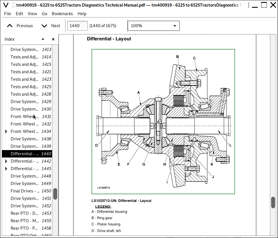
Differential - Layout
Differential - Power Flows
Differential - Oil Flows
Group 20C: Final Drives
Drive Systems - Final Drives, Summary of References
Final Drives - Operation and Layout
Group 20D: Rear PTO Options
Drive Systems - Rear PTO Options, Summary of References
Rear PTO - Description
Rear PTO - Modulating Valve with Lever Detent
Rear PTO - PTO Clutch and PTO Brake
Rear PTO Options - 540 rpm Power Flow
Rear PTO Options - 540/1000 rpm Power Flows
Section 260: Steering and Brakes
Group 05: Introductory Checks
Steering and Brakes - Test and Adjustments, Summary of References
Steering and Brakes - Steering, Preliminary Check
Steering and Brakes - Brakes, Preliminary Check
Group 10: Operational Checks
Steering and Brakes - Operational Checks, Summary of References
Steering and Brakes - Safety Measures
Steering and Brakes - Checking the Steering
Steering and Brakes - Check the Brakes
Group 15: Tests and Adjustments
Steering and Brakes - Tests and Adjustments, Summary of References
Steering and Brakes - Special Tools, Summary of References
Steering and Brakes - Connecting SensoControl Test Equipment
Tests and Adjustments - Specifications
Steering and Brakes - Check the Steering Unit
Steering and Brakes - Check the Brake System
Steering and Brakes - Bleed the Brakes
Tests and Adjustments - Adjust the Brake Pedals and Switches
Tests and Adjustments - Check and Adjust the Handbrake
Tests and Adjustments - Check the Hydraulic Trailer Brake Valve
Group 20A: Hydrostatic Steering
Steering and Brakes - Hydrostatic Steering, Summary of References
Steering and Brakes - Description of Steering Valves, Operation
Group 20B: Brake Valve
Steering and Brakes - Brake Valve, Summary of References
Steering and Brakes - Brake Valve, Description
Steering and Brakes - Two-Stage Brake Valve, Operation
Group 20C: Rear Wheel Brakes
Steering and Brakes - Rear Wheel Brakes, Summary of References
Rear Wheel Brakes - Operation and Layout
Group 20D: Handbrake
Steering and Brakes - Handbrake, Summary of References
Handbrake - Operation and Layout (Tractor Models up to 6630)
Group 20E: Hydraulic Trailer Brake
Steering and Brakes - Trailer Brake Valve, Summary of References
Steering and Brakes - Ascertain Pressure Ratio
Steering and Brakes - Hydraulic Trailer Brake Valve, Description
Section 270: Hydraulic System
Group 10: Operational Checks
Hydraulic System - Operational Checks
Group 15: Tests and Adjustments
Hydraulic System - Tests and Adjustments, Summary of References
Hydraulic System - Special Tools, Summary of References
Hydraulic System - Safety Measures for Hydraulic Checks
Hydraulic System - Worksheet for the Hydraulic System Diagnostics
Hydraulic System - Heat Up Hydraulic Oil
Hydraulic System - Oil Pressure Test Points
Hydraulic System - Check the LS Oil Pressure for Steering
Hydraulic System - Check the Oil Pressure for Steering
Hydraulic System - Check and Adjust System Oil Pressure
Hydraulic System - Check Lube Oil Pressure
Hydraulic System - Hydraulic Pump, Check Rate of Delivery
Hydraulic System - Selective Control Valves, Check for Leaks at Valve Spools
Hydraulic System - Hitch Valve, Check and Adjust Pressure Relief Valve
Hydraulic System - Hitch Valve, Check for Leaks
Hydraulic System - Check and Adjust Hitch Control
Hydraulic System - Hitch, Control Lever Friction Adjustment
Group 20: Theory of Operation
Hydraulic System - Theory of Operation, Summary of References
Hydraulic System - Hydraulic Circuit Diagram and Theory of Operation
Hydraulic System - Priority Valve, Theory of Operation
Group 20A: Oil Filter and Hydraulic Pump
Hydraulic System - Oil Filter and Hydraulic Pump, Summary of References
Hydraulic System - Hydraulic Oil Filter, Operation
Hydraulic System - Hydraulic Pump, Operation
Hydraulic System - Hydraulic Oil Primary Filter, Component Information
Hydraulic System - Hydraulic Oil Filter, Component Information
Hydraulic System - Hydraulic Pump, Component Information
Group 20B: Hitch
Hitch - Summary of References
Hitch - Hitch Control, Operation
Hitch - Hitch Control Valve, Operation
Group 20C: Selective Control Valves
Selective Control Valves - Summary of References
Selective Control Valves - Operation
Section 299: Special Tools
Group 05: Special Tools (Dealer-Fabricated)
DFLX9 - Adjusting Tool
DFLX10 - Holding Tool
DFLX12 - CAN BUS - E-SCV/E-ICV and CAN BUS - Vehicle/Power Train
DFLX14 - Solenoid Valve Test Harness
DFLX39 - Support
Group 10: Special Tools (Available as Spare Parts)
AR52361 - Socket
D01019AA - Single-Stage, Manually Operated Pump
D05104ST - Pump
FKM10002 / JT05470 - Universal Pressure Test Kit
FKM10242 - Pressure Gauge
FKM10443 - Charging Valve
FKM10444 - Electronic Refrigerant Leak Detector
FKM10445 - Universal Pressure Test Kit
FKM10447 - MINI CAN
FKM10464 - Single-Acting Hydraulic Ram
FKM10470 - Pressure Measuring System (Stage 1)
FKM10471 - Pressure Measuring System (Stage 2)
FKM10472 - Flow Measurement System
FKM10472-4 - Temperature Sensor
FKM10474 - Fill and Check Device
Adjusting Tool FKM10475
JDG839 - Adapter
JDH43A - Tester for Pressure-Relief Valves
JT03248 - Fitting
JT05470 / FKM10002 - Universal Pressure Test Kit
Pressure Gauge JT05473
JT05719 - Hand-Held Digital Tachometer
JT05791A or JDG1478 - Analog/Digital Multimeter
JT05800 - Digital Thermometer
JT07115 - Pressure Test Kit
JT07120 - Adjustable Restrictor
KJD10128 - Fitting
KJD10194 - Pressure Gauge Set for Air Brake System
KJD10265 - Test Harness
KJD10431 - Flow Tester
FKM10440 - RD5N Vacuum Pump
KJD10352 - Adapter
KJD10444 - Pressure Tool
KJD10502 - Adapter Plate
KJD10292 - Test Harness
RE200689 - Performance Monitor
![]()