
John Deere Tractors 6225, 6325, 6425, 6525 Repair Service Manual (TM401019)

John Deere Tractors 6225, 6325, 6425, 6525 Repair Service Manual (TM401019)
tm401019 - 6225 to 6525 Tractors Repair Technical Manual.pdf
Complete Repair Service Technical Manual for John Deere Tractors 6225, 6325, 6425, 6525 (European Model), with all the service information to maintain, repair, rebuild like professional mechanics.
John Deere 2WD or MFWD - European Tractors 6225, 6325, 6425, 6525 workshop technical manual (repair) includes:
* Numbered table of contents easy to use so that you can find the information you need fast.
* Detailed sub-steps expand on repair procedure information
* Numbered instructions guide you through every repair procedure step by step.
* Notes, cautions and warnings throughout each chapter pinpoint critical information.
* Bold figure number help you quickly match illustrations with instructions.
* Detailed illustrations, drawings and photos guide you through every procedure.
* Enlarged inset helps you identify and examine parts in detail.
PRODUCT DETAILS:
Total Pages: 1,601 pages
File Format: PDF (bookmarked, ToC, Searchable, Printable, high quality)
Language: English
MAIN SECTIONS
Foreword
Safety
Safety Information
General Information
Specifications
Tune-Up
Inspection Before Delivery
Engine
Removal and Installation of Components
Fuel, Air Intake, Cooling and Exhaust Systems
Speed Control
Fuel System
Air Intake System
Cooling System
Cold-Weather Starting Aids
Exhaust System
Electrical System
Connectors
Charging Circuit
Starting Motor Circuit
Electrical Components
Electronic Control Units
Removal and Installation of Electronic Control Units
SyncroPlus Transmission
Removal and Installation of Components
Transmission Shift Controls
Perma Clutch II Module
Gear Transmission
PowrReverser Transmission
Removal and Installation of Components
Transmission Shift Controls
PowrReverser Module
Gear Transmission
Range Transmission
Drive Systems
Removal and Installation of Components
U-Jointed Shafts and Torsion Damper
Front-Wheel Drive Clutch
Differential
Differential - 3D Animation
Hydraulic Pump Drive
Final Drives
Final Drives - 3D Animation
Rear PTO
Steering and Brakes
Hydrostatic Steering
Steering Cylinder
Brake Valve
Rear Wheel Brakes
Handbrake
Hydraulic Trailer Brake
Hydraulic System
Controls
Oil Filter and Hydraulic Pump
Valves
Hitch
Selective Control Valves (SCVs) and Couplers
Miscellaneous
Removal and Installation of Components
Main Frame
Front Wheels, Rear Wheels and Fenders
Trailer Mounting and Swinging Drawbar
Hydraulic Pick-Up Hitch
Operator's Station
Removal and Installation of Components
Controls and Instruments
2-Post ROPS
Operator's Seat
Special Tools
Special Tools (Dealer-Fabricated)
Special Tools (Available from the Dealer)
tm401019 - 6225 to 6525TractorsRepair
Table of Contents
Foreword
Section 05: Safety
Group 05: Safety Information
Recognize Safety Information
”Important” Information
”Note” Information
Prevent Machine Runaway
Handle Fluids Safely—Avoid Fires
Prevent Battery Explosions
Prepare for Emergencies
Prevent Acid Burns
Avoid High-Pressure Fluids
Service Cooling System Safely
Remove Paint Before Welding or Heating
Avoid Heating Near Pressurized Fluid Lines
Work In Ventilated Area
Wear Protective Clothing
Practice Safe Maintenance
Park Machine Safely
Use Proper Lifting Equipment
Construct Dealer-Made Tools Safely
Support Machine Properly
Work in Clean Area
Illuminate Work Area Safely
Service Machines Safely
Use Proper Tools
Service Tires Safely
Service Front-Wheel Drive Tractor Safely
Safety Information - Air Brake System
Avoid Eye Contact With Radar
Keep ROPS Installed Properly
Replace Safety Signs
Dispose of Waste Properly
Live With Safety
Safety Measures on Electronic Control Units
Section 10: General Information
Group 05: Specifications
Specifications (Summary of References)
Engine Specifications
Cooling System
Electronic Fuel System with Common Rail (Denso)
Air Intake System
Electrical System
Hydrostatic Steering System
Clutch
SyncroPlus Transmission
PowrReverser Transmission
Rear PTO
Front PTO
Differential assembly
Differential lock
Final drives
Front-Wheel Drive
Hydraulic Brakes
Handbrake
Parking Lock
Hydraulic system with gear-type pump (PC system)
Rockshaft
Ground Speeds
Front and Rear Wheels
Dimensions and Weights
Capacities
Handling and Storing Diesel Fuel
Diesel Fuel
Bio-Diesel Fuel
Diesel Engine Oil and Filter Service Intervals
Lubricity of Diesel Fuel
Diesel Engine Break-In Oil
Diesel Engine Oil
Transmission and Hydraulic Oil
Front-Wheel Drive Axle Oil
Diesel Engine Coolant
Heavy Duty Diesel Engine Coolant
Supplemental Coolant Additives
Grease
Oil Filters
Mixing of Lubricants
Lubricant Storage
Operating in Warm Temperature Climates
Alternative and Synthetic Lubricants
Unified Inch Bolt and Screw Torque Values
Metric Bolt and Screw Torque Values
Hydraulic system inch fitting torques
Hydraulic system metric fitting torques
Product identification and component serial numbers
Engine Serial Number
Transmission serial number
Front wheel drive axle serial number
Sub-assembly serial numbers
Group 10: Tune-Up
General References, Tune-Up
Specifications
Using High-Pressure Washers
Preliminary Engine Test
Tractor Tune-Up
Removing and Cleaning the Primary Air Cleaner Element
Checking the Air Cleaner Safety Element
Installing the Primary Air Cleaner Element
Checking Air Intake System Connections for Leaks
Checking Air Intake Hoses
Checking the Crankcase Vent Hose for Clogging
Cleaning Dirt from Radiator Screen
Adjust the Hood
Cleaning Radiator
Check Cap on Expansion Tank
Check the Radiator for Leaks
Checking the Engine's Thermostat
Checking the Fuel Transfer Pump Operation
Check Fuel Filter
Bleed Fuel System
Cleaning Water Trap
Check Transmission/Hydraulic System Oil Level
Check the Oil Sight-Glass (when the Tire Combination has been Changed)
Run Engine until it is Warm and Check Engine Speeds
Check Electrolyte Level of Battery
Check the Neutral Start Circuit
Checking the Starting Motor Operation
Checking the Lighting Circuit
Final Engine Check
Tractor Operation Check
Group 15: Inspection Before Delivery
Inspection Before Delivery
Section 20: Engine
Group 00: Removal and Installation of Components
Engine - Removal and Installation of Components, Summary of References
Special Tools
Specifications
Repair Information
Remove the Engine
Install the Engine
Section 30: Fuel, Air Intake, Cooling and Exhaust Systems
Group 05: Speed Control
Speed Control (Summary of References)
General Information
Specifications
Replace Accelerator Pedal Assembly
Remove Accelerator Pedal Potentiometer
Group 10: Fuel System
Fuel System - Summary of References
Fuel System - Special Tools, Summary of References
General Information
Remove the Fuel Tank
Install the Fuel Tank
Replace Fuel Level Sensor
Replace the Fuel Transfer Pump
Changing the Fuel Filters
Bleed the Fuel System
Group 15: Air Intake System
Fuel, Air Intake, Cooling and Exhaust Systems - Air Intake System, Summary of References
General Information
Air Cleaner - Exploded View
Replacing the sending unit for air cleaner restriction (B02)
Group 20: Cooling System
Cooling System - Summary of References
General Information
Specifications
Remove and Install the Transmission Oil Cooler
Remove the Radiator
Change the Fan or the Viscous Fan Drive
Remove and Install the Charge Air Cooler
Remove and Install the Expansion Tank
Install the Radiator
Fill Cooling System with Coolant
Relieve the Tension on the Drive Belt
Replace Drive Belt
Replacing the Drive Belt Tensioner
Remove and Install Fan Console (with Mechanical Coolant Pump)
Group 25: Cold-Weather Starting Aids
Cold-Weather Starting Aids - Summary of References
Fuel preheater
Group 30: Exhaust System
Exhaust System - Summary of References
General Information
Specifications
Exhaust System to Top Right
Exhaust System to Bottom Right
Section 40: Electrical System
Group 05: Connectors
Connectors - Summary of References
Special Tools
General
Using high-pressure washers
Disconnecting electrical circuits
Strip Wire Ends
Install a Terminal
WEATHER PACK Connectors
METRI PACK Connectors with Terminal Lock at the Rear
METRI PACK Connectors with Terminal Lock at the Front
METRI PACK Connectors
Connectors for Electronic Control Units
Connectors
CRIMP SNAP IN Connectors
KOSTAL Connectors
DEUTSCH Connectors
Individual Terminals
Fuse and Relay Boxes
Group 10: Charging Circuit
Charging Circuit - Summary of References
Special Tools
Specifications
Repairing the Alternator
Disconnecting Electrical Circuits
Relieve Drive Belt Tension
Remove/Install the Alternator
Remove and Install the Pulley
Group 15: Starting Motor Circuit
Starter Motor Circuit - Summary of References
Specifications
Repairing the Starter Motor
Disconnecting Electrical Circuits
Remove and Install Starting Motor
Group 20: Electrical Components
Electrical Components – Summary of References
General information
Disconnecting electrical circuits
Adjusting the headlights
Adjust lights on the cab frame
Safety Instructions for Replacing a Halogen Bulb
Safety Instructions for Replacing Xenon (HID) Bulbs and Ballast Units
Replacing Xenon (HID) Worklights and Ballast Units
Section 45: Electronic Control Units
Group 05: Removal and Installation of Electronic Control Units
Electronic Control Units - Summary of References
Disconnecting electrical circuits
Instructions when Replacing a Control Unit
Safety Information
Replace ECU Control Unit
Section 50: SyncroPlus Transmission
Group 00: Removal and Installation of Components
SyncroPlus Transmission - Removal and Installation of Components, Summary of References
Special Tools
Specifications
Remove Clutch Housing
Install Clutch Housing
Remove and Install Gear Transmission
Group 05: Transmission Shift Controls
SyncroPlus Transmission - Transmission Shift Controls, Summary of References
Specifications
Remove Shift Unit for Gear and Range Transmissions
Recondition Shift Unit for Gear and Range Transmissions
Install Shift Unit for Gear and Range Transmissions
Check and Adjust the Shift Mechanisms/Linkages
Check and Adjust the Park Lock
Adjust the Clutch Pedal
Group 10: Perma Clutch II Module
SyncroPlus Transmission - Perma Clutch II Module, Summary of References
Special Tools, Summary of References
Specifications
Remove Clutch
Recondition Clutch
Install Clutch
Remove Transmission Oil Pump
Recondition Transmission Oil Pump
Install Transmission Oil Pump
Exploded View of Valves and Other Hydraulic Components
Recondition Engagement Override Valve
Recondition Cooling Oil Valve
Recondition Cooling Oil Pilot Valve
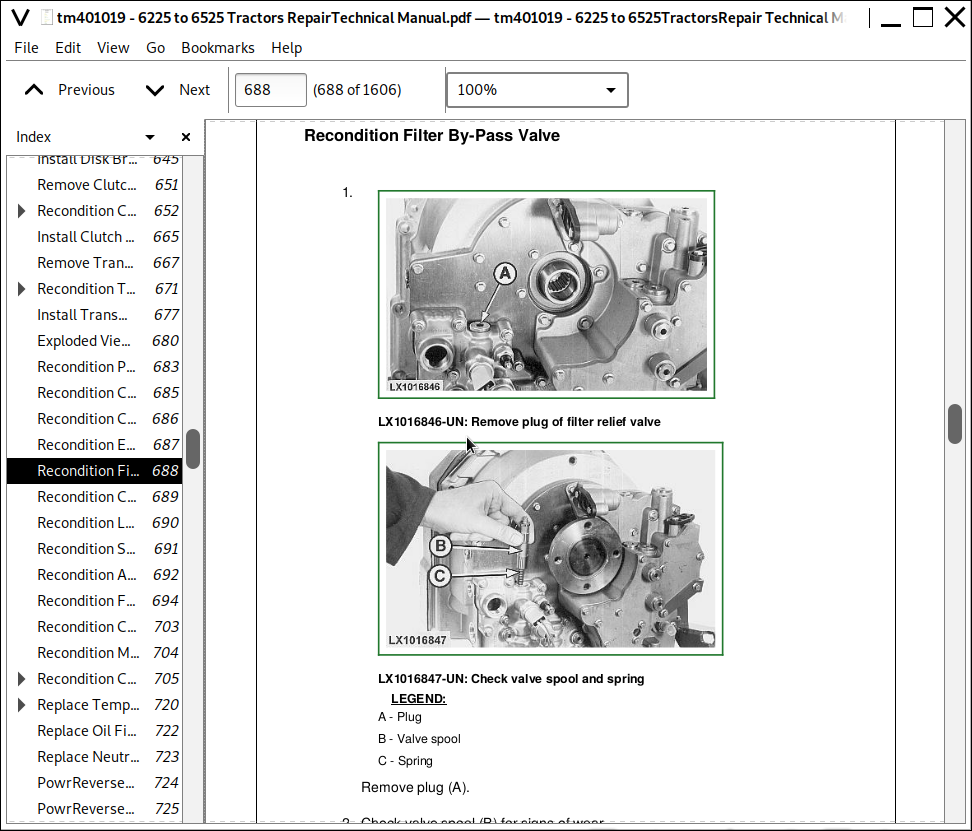
Recondition Filter By-Pass Valve
Recondition Pressure-Regulating Valve
Recondition Lube Relief Valve
Recondition Cooler Relief Valve
Recondition Clutch Pedal Valve
Replace Temperature and Pressure Sensors
Group 15: Gear Transmission
SyncroPlus Transmission - Gear Transmission, Summary of References
Special Tools, Summary of References
Specifications
Gear Transmission - Sectional View
Disassemble Gear Transmission
Recondition Gear Transmission
Preparation for Installing the Gear Transmission
Recondition Shift Cover
Adjust Shift Mechanism at Gear Transmission
Adjust Neutral Start Switch
Section 51: PowrReverser Transmission
Group 00: Removal and Installation of Components
PowrReverser Transmission - Removal and Installation of Components, Summary of References
Special Tools
Specifications
Remove PowrReverser Module
Install PowrReverser Module
Remove Gear Transmission
Install Gear Transmission
Remove Range Transmission
Install Range Transmission
Group 05: Transmission Shift Controls
PowrReverser Transmission - Transmission Shift Controls, Summary of References
Specifications
Remove Shift Unit for Gear and Range Transmissions
Recondition Shift Unit for Gear and Range Transmissions
Install Shift Unit for Gear and Range Transmissions
Check and Adjust the Shift Mechanisms/Linkages
Check and Adjust the Park Lock
Recondition Forward/Reverse Control
Adjust Reverse Drive Linkage with Mechanically Actuated PowrReverser Module
Adjust Reverse Drive Lever with Mechanically Actuated PowrReverser Module
Adjust the Clutch Pedal
Group 10: PowrReverser Module
PowrReverser Transmission - PowrReverser Module, Summary of References
Special Tools, Summary of References
Repair Specifications
PowrReverser Module, Sectional View
Components of Power Train
Remove Disk Brake
Recondition Disk Brake
Install Disk Brake
Remove Clutch and Planetary Carrier
Recondition Clutch and Planetary Carrier
Install Clutch and Planetary Carrier
Remove Transmission Oil Pump
Recondition Transmission Oil Pump
Install Transmission Oil Pump
Exploded View of Valves and Other Hydraulic Components
Recondition Pressure-Regulating Valve
Recondition Cooling Oil Pilot Valve
Recondition Cooling Oil Valve
Recondition Engagement Override Valve
Recondition Filter By-Pass Valve
Recondition Cooler Relief Valve
Recondition Lube Relief Valve
Recondition Sump Valve
Recondition Accumulator Piston
Recondition Forward/Reverse Valve
Recondition Cooling Oil Control Valve (Travel Direction)
Recondition Modulator Valve
Recondition Clutch Pedal Valve
Replace Temperature and Pressure Sensors
Replace Oil Filter
Replace Neutral Start Switch
Group 15: Gear Transmission
PowrReverser Transmission - Gear Transmission, Summary of References
Special Tools, Summary of References
Specifications
Gear Transmission - Sectional View
Disassembly of Gear Transmission
Recondition Gear Transmission
Preparation for Installing the Gear Transmission
Recondition Shift Cover
Adjust the shift mechanism on the gear transmission
Group 20: Range Transmission
Range Transmission - Reconditioning, Summary of References
Specifications
Range Transmission - Sectional View
Disassemble the Range Transmission
Exploded View of Differential Drive Shaft
Assemble the Differential Drive Shaft
Install the Differential Drive Shaft and Adjust the Cone Point
Exploded View of Drive Shaft and Park Lock
Exploded View of Range Shift Mechanism
Assemble the Range Transmission
Install the Park Lock Camshaft
Measure Play at the Drive Shaft
Adjust the Range Shift Mechanism
Recondition Shift Cover
Section 56: Drive Systems
Group 00: Removal and Installation of Components
Drive Systems - Removal and Installation of Components, Summary of References
Special Tools
Specifications
Remove the Front-Wheel Drive Clutch
Install the Front-Wheel Drive Clutch
Remove Differential Housing
Install Differential Housing
Remove Final Drives
Install Final Drives
Remove Rear PTO
Install Rear PTO
Group 05: U-Jointed Shafts and Torsion Damper
Drive Systems - U-Jointed Shafts and Torsion Damper, Summary of References
U-Jointed Shafts and Torsion Damper - Specifications
Remove U.J. Shaft (Front-Wheel Drive)
Reconditioning the U.j. Shaft (Front-Wheel Drive)
U-Jointed Shafts and Torsion Damper - Install U.J. Shaft (Front-Wheel Drive)
Remove Engine U.J. Shaft
Remove and Install Ring-Shaped Cooler
U-Jointed Shafts and Torsion Damper - Remove Torsion Damper
Changing the Torsion Damper Bearings
U-Jointed Shafts and Torsion Damper - Install Torsion Damper
Install Engine U.J. Shaft
Group 10: Front-Wheel Drive Clutch
Drive Systems - Front-Wheel Drive Clutch, Summary of References
Special Tools
Front-Wheel Drive Clutch - Repair Specifications
Recondition Y03 - Solenoid Valve for Front-Wheel Drive
Front-Wheel Drive Clutch - Cross Section
Front-Wheel Drive Clutch - Exploded View
Disassemble Front-Wheel Drive Clutch
Recondition the Front Wheel Drive Clutch
Assemble Front-Wheel Drive Clutch
Group 15: Differential
Drive Systems - Differential, Summary of References
Differential - Repair Specifications
Replace the Wheel Speed Sensor (B09 or B35 or B84)
Replace Solenoid Valve for Differential Lock (Y05)
Differential - Sectional View
Differential - Exploded View
Remove the Differential
Recondition the Differential
Install the Differential
Differential - Adjust Tapered Roller Bearing and Backlash
Group 153D: Differential - 3D Animation
Differential - 3D-Animation - Summary of References
Replace the Sensor (B09 or B35 or B84) - 3D Animation
Remove the Differential - 3D Animation
Recondition the Differential - 3D Animation
Install the Differential - 3D Animation
Group 20: Hydraulic Pump Drive
Drive Systems - Hydraulic Pump Drive, Summary of References
Special Tools
Repair Specifications
Hydraulic Pump Drive - Sectional View
Remove Hydraulic Pump Drive
Install Hydraulic Pump Drive
Adjust the Hydraulic Pump Drive
Group 25: Final Drives
Drive Systems - Final Drives, Summary of References
Special Tools
Specifications
Final Drives - Sectional View
Final Drives - Exploded View
Disassemble the Final Drives
Recondition the Final Drives
Assemble the Final Drives
Final Drives - Check and Adjust Rolling Drag Torque
Group 253D: Final Drives - 3D Animation
Final Drives - 3D-Animation - Summary of References
Disassemble, Recondition and Assemble the Final Drives (Standard Version) - 3D Animation
Disassemble, Recondition and Assemble the Final Drives (Heavy-Duty Version) - 3D Animation
Group 30: Rear PTO
Drive Systems - Rear PTO, Summary of References
Rear PTO - Special Tools
Rear PTO - Specifications
Rear PTO - Replace the Output Shaft Seal Ring
Replace the O-Ring on Reversible PTO
Rear PTO - Sectional View
PTO Clutch - Exploded View
Remove PTO Clutch
Recondition the PTO Clutch
Repair of PTO Brake
Install PTO Clutch
PTO Drive Train - Sectional View
PTO Drive Train - Exploded View
Remove PTO Drive Train (Reversible)
Recondition the Output Shaft (Reversible)
Recondition the Countershaft (Reversible)
Install PTO Drive Train (Reversible)
Rear PTO - Recondition the Output Shaft (540 rpm)
Adjust Tapered Roller Bearing of Output Shaft (540 rpm)
Adjust the Tapered Roller Bearing of the Countershaft
Adjust the Tapered Roller Bearing of the Bearing Support
Rear PTO - Remove Modulating Valve
Rear PTO - Recondition the Modulating Valve
Rear PTO - Install Modulating Valve
Replace B06 - Rear PTO Speed Sensor
Recondition Oil Sight-Glass
Section 60: Steering and Brakes
Group 05: Hydrostatic Steering
Steering and Brakes - Hydrostatic Steering, Summary of References
Hydrostatic Steering - Special Tools
Specifications
Preliminary Work
Disconnecting/Connecting Steering or Brake Hoses
Steering Valve - Removal
Disassembling the Steering Valve
Exploded View of Steering Valve
Assembling the Steering Valve
Hydrostatic Steering - Adjust Shock Valves
Steering Valve - Installation
Group 10: Steering Cylinder
Steering and Brakes - Steering Cylinder, Summary of References
Steering Cylinder - General Information
Steering Cylinder - Specifications
Repair Information
Remove the Steering Cylinder
Recondition the Steering Cylinder
Install the Steering Cylinder
Group 15: Brake Valve
Steering and Brakes - Brake Valve, Summary of References
Brake Valve - Special Tools
Brake Valve - Repair Specifications
Repair Instructions
Single-Stage Brake Valve - Exploded View
Remove Single-Stage Brake Valve
Recondition Single-Stage Brake Valve
Install Single-Stage Brake Valve
Two-Stage Brake Valve - Exploded View
Remove the Two-Stage Brake Valve
Recondition Two-Stage Brake Valve
Install Two-Stage Brake Valve
Group 20: Rear Wheel Brakes
Steering and Brakes - Rear Brakes, Summary of References
Special Tools
Specifications
Rear Brakes - Exploded View
Remove the Rear Brakes
Install the Rear Brakes
Check Brake Pistons for Return Movement and Leakage
Group 25: Handbrake
Steering and Brakes - Handbrake, Summary of References
Handbrake - Repair Specifications
Exploded View of Handbrake
Remove Handbrake
Install Handbrake
Handbrake - Replace Handbrake Cable
Group 30: Hydraulic Trailer Brake
Steering and Brakes - Hydraulic Trailer Brake, Summary of References
Hydraulic Trailer Brake - Repair Specifications
Repair Instructions
Hydraulic Trailer Brake - Change Trailer Brake Valve
Section 70: Hydraulic System
Group 05: Controls
Controls - Summary of References
Hitch Valve - Remove and Install Control Levers
Selective Control Valves - Remove and Install Control Lever(s)
Group 10: Oil Filter and Hydraulic Pump
Oil Filter and Hydraulic Pump - Summary of References
Specifications
Bleed Air from Hydraulic Pump
Remove and Install Hydraulic Oil Primary Filter
Recondition the Hydraulic Oil Filter
Remove the Hydraulic Pump
Hydraulic Pump - Remove Installation Plate with Lube Oil Valve
Remove and Install the Lube Oil Valve
Hydraulic Pump - Install Installation Plate with Lube Oil Valve
Install the Hydraulic Pump
Group 15: Valves
Recondition the Hydraulic System Valves - Summary of References
Other Material
Specifications
Hydraulic System - General Instructions on Safety and Repair
Remove and Install Priority Valve
Recondition the Priority Valve
Remove the Hitch Valve
Hitch Valve - Remove Control Valve
Hitch Valve - Recondition the Control Valve
Hitch Valve - Install Control Valve
Hitch Valve - Remove and Install Control Lever Console
Hitch Valve - Recondition the Regulating Components
Install Hitch Valve
Group 20: Hitch
Recondition Hitch - Summary of References
Specifications
Hitch - Remove and Install Rockshaft
Hitch - Remove Lift Cylinders
Hitch - Recondition the Lift Cylinders
Hitch - Install Lift Cylinders
Hitch - Center Link, Remove Support
Hitch - Center Link, Recondition Support
Hitch - Center Link, Install Support
Group 25: Selective Control Valves (SCVs) and Couplers
Recondition Selective Control Valves and Couplers - Summary of References
Other Material
Specifications
Remove the Selective Control Valves
Recondition Selective Control Valves without Float Position
Recondition Selective Control Valves with Float Position
Selective Control Valves - Recondition Inlet Plate
Selective Control Valves - Recondition Outlet Plate
Install the Selective Control Valves
Selective Control Valves - Recondition the Couplers
Section 80: Miscellaneous
Group 00: Removal and Installation of Components
Miscellaneous - Removal and Installation of Components, Summary of References
Special Tools
Specifications
Preliminary Work for Removal of the Main Frame
Remove Main Frame
Install Main Frame
Remove the Front Axle
Install the Front Axle
Remove Front-Wheel Drive Axle
Install Front-Wheel Drive Axle
Remove Front Axle Support
Install Front Axle Support
Group 05: Main Frame
Miscellaneous - Main Frame, Summary of References
Main Frame - Repair Specifications
Recondition Main Frame without TLS Front-Wheel Drive Axle
Group 15: Front Wheels, Rear Wheels and Fenders
Front Wheels, Rear Wheels and Fenders – Summary of References
Special Tools
Specifications
Pivoting Front Fender
Remove the Front and Rear Wheels
Recondition the Front and Rear Wheels
Install the Front and Rear Wheels
Group 20: Trailer Mounting and Swinging Drawbar
Trailer Mounting and Swinging Drawbar - Summary of References
Repair Specifications
Check the Manually-Operated Trailer Hitch for Wear
Checking the Manually-Operated Hitch for Wear (Italy and Spain Only)
Check Remote Controlled Trailer Hitch for Wear
Checking the Tow-Hook for Wear
Check the Hitch Ball for Wear
Checking the Swinging Drawbar for Wear
Install Rigid Trailer Mounting
Install the Guide Rails
Repair of Automatic Trailer Hitch
Remote Control for Automatic Trailer Hitch
Reconditioning the height-adjustable trailer hitch (Italy and Spain only)
Swinging Drawbar
Swinging Drawbar with Pick-Up Hitch
Adjusting the Retaining Strap
Group 30: Hydraulic Pick-Up Hitch
Pick-Up Hitch - Summary of References
Specifications
Pick-Up Hitch — General Safety and Repair Information
Check Tow Hook on Pick-Up Hitch for Wear
Removing and Installing the Pick-Up Hitch
Pick-Up Hitch - Exploded View
Pick-Up Hitch - Control Lever and Lift Links
Pick-Up Hitch - Hydraulic Parts
Recondition the Retainer Spring
Repairing the Latch Housing
Recondition the Hydraulic Cylinder
Adjusting the Lift Links
Adjusting the Guide Stop
Adjust the Locking Pin
Pick-Up Hitch — Operational Check
Section 90: Operator's Station
Group 00: Removal and Installation of Components
Operator's Station - Removal and Installation of Components, Summary of References
Specifications
Remove Operator's Station
Install Operator's Station
Check and Adjust the Shift Mechanisms/Linkages
Group 05: Controls and Instruments
Summary of References (Controls and Instruments)
Preliminary Work
Replace Bulbs on the Instrument Unit
Group 15: 2-Post ROPS
2-Post ROPS (Summary of References)
2-Post ROPS (Summary of References)
Keep ROPS Installed Properly
Specifications
Torques for Hardware on Platform Mounting (with 2-Post ROPS)
Torques for Hardware on Platform Mounting (without 2-Post ROPS)
Group 20: Operator's Seat
Operator's Seat (Summary of References)
Specifications
Replace Lap-Strap (Left-Hand Side)
Replace Lap-Strap (Right-Hand Side)
Attach Operator's Seat
Exploded View of Comfort Seat MSG44
Section 99: Special Tools
Group 05: Special Tools (Dealer-Fabricated)
DFLX1 - Adapter Strut
DFLX2 - Suspension Device for Clutch Housing of the SyncroPlus Transmission and the PowrReverser Module
DFLX4 - Suspension Device for AutoPowr/IVT Transmission
DFLX5 - Lifting Eye for Operator's Cab
DFLX6 - Bushing
DFLX7 - Turning Device
DFLX8 - Thrust Pieces
DFLX10 - Holding Tool
DFLX13 - Holding Device
DFLX14 – Suspended MFWD Axle Housing Bracket
DFLX15 - Holding Device for Tractor Components
DFLX16 - Wooden Block
DFLX17 - Assembly and Guide Mandrels
DFLX20 - Unlocking Device for Park Lock
DFLX21 - Special Wrench
DFLX22 – Socket Wrench Insert
DFLX23 – Socket Wrench Insert
DFLX24 - Seal Installer
DFLX25 – Driver
DFLX27 – Driver
DFLX39 - Support
DFLX40 - Mandrel
DFLX41 – Socket Wrench Insert
DFRW79 – Piston Holding Tool
Group 10: Special Tools (Available from the Dealer)
D01019AA - Single-Stage, Manually Operated Pump
D01042AA – Load-Positioning Sling
D01045AA - Bushing, Bearing and Seal Driver Set
D01210AA - Slide Hammer Puller
D05007ST - Tractor Splitting Stand
FKM10427 - Crimping Pliers
FKM10455 - Extraction Tool
FKM10456 - Extraction Tool
FKM10457 - Extraction Tool
FKM10461 - Wiring Harness Repair Kit
FKM10464 - Single-Acting Hydraulic Ram
FKM10469 - Crimping Pliers
JDE83 – Flywheel Turning Tool
JDG18 - Snap Ring Tool
JDG19 – Special Mounting Brackets
JDG23 – Lifting Sling
JDG359 - Electrical Repair Tool Kit
JDG360 - DEUTSCH Crimping Pliers
JDG361 - Extraction Tool
JDG362 - Extraction Tool
JDG364 - Extraction Tool
JDG708 - AMP Crimping Tool
JDG749 - 1,30 m (52 in.) Torque wrench extension
JDG750 – Swivel Socket
JDG754 - Spring Compressor
JDG765 - Bushing Installer
JDG772 - Planetary Installation Tool
JDG775 - Seal Installer
JDG776 - Extraction Tool
JDG777 - Extraction Tool
JDG783 - Crimping Pliers
JDG785 - Extraction Tool
JDG820 – Flywheel Turning Tool
JDG1369 - Terminal Extraction Tool
JDG1655A - Suspension Device for PowrQuad Transmission
JDG1725 - Extraction Tool
JDG1727 - Crimping Pliers
JDG1744 - Electrical Repair Tool Kit
JT02043 - Support Stand
JT02044 - Support Stand
JT03248 - Fitting
JT05723 – Medium-Duty Rear Tractor Splitting Stand
JT05724 – Medium-Duty Front Tractor Splitting Stand
JT05725 – Universal Support Stand
JT07211 - Support Stand
KJD10168A - Ring Nut Socket
KJD10169B - Special Puller
KJD10172 - Lifting Tool
KJD10173 - Special Tool
KJD10177 - Pressure Tool
KJD10227 - Special Tool
KJD10416 - Driver
KJD10426 - Special Tool
FKM10478 - Service Unit
KJD10527 - Extraction Tool
KJD10581 - Trolley for Wheel Removal and Installation
KLM10019-1 - Crimping Pliers
KLM10019-4 - Extraction Tool
OTC7062A - Holder
OTC27489 - Handle
RE37996 - Adjusting Tool
![]()