
John Deere Tractors 6230, 6330, 6430, 6530, 6630,7130, 7230 Diagnosis and Tests Service Technical Manual (TM400719)
Complete Diagnosis & Tests Technical Manual with electrical wiring diagrams for John Deere Tractors 6230, 6330, 6430, 6530, 6630, 7130, 7230, with all the workshop information to maintain, diagnose, and rebuild like professional mechanics.
John Deere 2WD or MFWD - North American Tractors 6230, 6330, 6430, 6530, 6630, 7130 & 7230 workshop Diagnosis & Tests technical manual includes:
* Numbered table of contents easy to use so that you can find the information you need fast.
* Detailed sub-steps expand on repair procedure information
* Numbered instructions guide you through every repair procedure step by step.
* Troubleshooting and electrical service procedures are combined with detailed wiring diagrams for ease of use.
* Notes, cautions and warnings throughout each chapter pinpoint critical information.
* Bold figure number help you quickly match illustrations with instructions.
* Detailed illustrations, drawings and photos guide you through every procedure.
* Enlarged inset helps you identify and examine parts in detail.
tm400719 - 6230—7230 Tractors Diagnostics - (North American Edition) Technical Manual.pdf
tm400719 - 6230—7230 Tractors Diagnostics - (North American Edition) Technical Manual.epub
Total Pages: 4,231 pages
File Format: PDF (bookmarked, ToC, Searchable, Printable, high quality) & EPUB/MOBI/AZW for Kindle/iPad/iPhone/Android.
Language: English
MAIN SECTIONS
Foreword
Serial Number Break 2009
General Information
Safety Measures
General References
Diagnostic Trouble Codes
BCU Control Unit
ECU Control Unit
EPC Control Unit
PRC Control Unit
Observable Symptoms
Electronics
Electronic Control Units
SyncroPlus Transmission
PowrReverser Transmission
PowrQuad Transmission
Drive Train (without Transmission)
Steering and Brakes
Hydraulic System
Operator's Cab
System Diagnostics
Electronics
PowrQuad Transmission
Die Kugeln (N) werden vorgespannt und der Steuerschieber bzw. Bedienungshebel wird in der Rastnut fur Zylinder ausfahren gehalten.Hydraulic System
Engine
General Information
Operational Checks
Tests and Adjustments
Fuel, Air Intake, and Cooling Systems
Tests and Adjustments
Fuel System
Air Intake System
Cooling System
Cold-Weather Starting Aids
Electrical System
Starting Motor and Charging Circuit
Fuel Preheater
Electrical Starting Aid
Instrument unit
Horn
Operator's Seat and Cigarette Lighter
Lights
Worklights
Radio, Dome Light and Console Light
Air Conditioning and Fan
Windshield wiper and washer
Rear window wiper and washer
Rotary Beacon
3-Terminal Power Outlet Socket (SAE)
3-terminal power outlet socket (ECE)
Connector for Accessories
BCU Control Unit (Electronic Hitch Control)
BCU Control Unit (Basic Functions)
Signal Socket and Service Socket
7-terminal power outlet socket (ECE)
7-Terminal Power Outlet Socket (SAE)
TSC Control Unit (Suspension)
CAN BUS Terminating Resistor
ECU Control Unit Level 16 (Electron. Engine Control) for 2V-HPCR Engine
Back-Up Alarm
EPC Control Unit (Transmission Control with PowrQuad Plus Transmission)
PRC Control Unit (Transm. Control with PowrRever. Transm. and Electr. Rev. Control)
SyncroPlus Transmission
Prewiring for GreenStar
Component Information - Connectors and Contacts
Component Information - Connectors (X001 to X249)
Component Information - Connectors (X250 to X499)
Component Information - Connectors (X500 to X749)
Component Information - Connectors (X750 to X999)
Component Information - Connectors (XGND)
Component Information - Wiring Harnesses
Component Information - Electrical Parts/Components
Component Information - Electrical Parts/Components (Actuators)
Component Information - Electrical Parts/Components (Sensors/Switches/Potentiometers)
Component Information - Electrical Parts/Components (Fuses/Relays/Diodes)
Component Information - Electrical Parts/Components (Headlamps/Lights)
Component Information - Electrical Parts/Components (Other)
Component Information - Ground Connections
Component Information - CAN BUS System
Electronic Control Units
Operation and General Information on Diagnostics
Interactive Tests
Interactive Calibrations
Information on How to Reprogram Control Units
Data BUS Systems
BCU Control Unit
ECU Control Unit
EPC Control Unit
PRC Control Unit
SyncroPlus Transmission
Operational Checks
Tests and Adjustments
Theory of Operation
PowrReverser Transmission
Operational Checks
Tests and Adjustments
Theory of Operation
PowrQuad Transmission
Operational Checks
Tests and Adjustments
Theory of Operation
Drive Train (without Transmission)
Operational Checks
Tests and Adjustments
Front-wheel drive clutch
Differential
Final Drives
Rear PTO Options
Steering and Brakes
Introductory Checks
Operational Checks
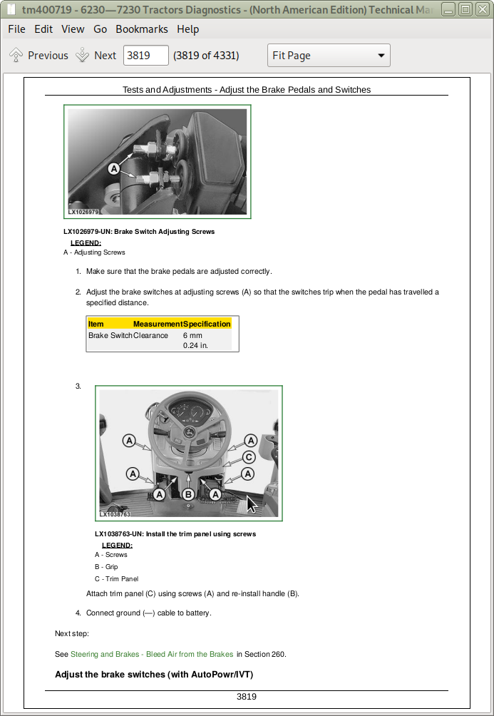
Tests and Adjustments
Hydrostatic Steering
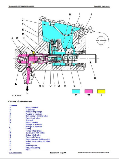
Brake valve
Rear Brakes
Hydraulic System
Operational Checks
Tests and Adjustments
Theory of Operation
Oil Filter, Charge Pump and Hydraulic Pump
Hitch
Selective Control Valves (SCVs)
Independent Control Valves (ICVs)
Hydraulic Block
Operator's Cab
Operational Checks
Tests and Adjustments
Ventilation/Heating
Air Conditioning System
Special Tools
Special Tools (Dealer-Fabricated)
Special Tools (Available as Spare Parts)
tm400719 - 6230—7230 TractorsDiagnostics -: (North American Edition)
Table of Contents
Foreword
Serial Number Break 2009
Section 210: General Information
Group 05: Safety Measures
General Information - Safety - Summary of References
Recognize Safety Information
”Important” Information
”Note” Information
Prevent Machine Runaway
Handle Fluids Safely—Avoid Fires
Prevent Battery Explosions
Prepare for Emergencies
Prevent Acid Burns
Avoid High-Pressure Fluids
Service Cooling System Safely
Remove Paint Before Welding or Heating
Avoid Heating Near Pressurized Fluid Lines
Work In Ventilated Area
Wear Protective Clothing
Practice Safe Maintenance
Park Machine Safely
Use Proper Lifting Equipment
Construct Dealer-Made Tools Safely
Support Machine Properly
Work in Clean Area
Illuminate Work Area Safely
Service Machines Safely
Use Proper Tools
Service Tires Safely
Service Front-Wheel Drive Tractor Safely
Avoid Eye Contact With Radar
Keep ROPS Installed Properly
Replace Safety Signs
Replace Safety Signs
Dispose of Waste Properly
Live With Safety
Safety Measures on Electronic Control Units
Servicing Electronic Control Units
Welding Near Electronic Control Units
Keep Electronic Control Unit Connectors Clean
Safety Instructions for Replacing a Halogen Bulb
Safety Instructions for Replacing Xenon (HID) Bulbs and Ballast Units
Group 10: General References
General Information - General References, Summary of References
General Information - Transmission and Hydraulic System, Introductory Checks
General Information - Inch Bolt and Cap Screws, Torque Values
General Information - Metric Bolt and Cap Screws, Torque Values
General Information - Hydraulic System Inch Fittings, Torque Values
General Information - Hydraulic System Metric Fittings, Torque Values
General Information - Electrical System, Component Identification Table
General Information - Electrical System, How to Read a Diagnostic Schematic
General Information - Electrical System, Lead Numbers and Color Codes
General Information - Electrical System, Symbols in Schematic, Wiring and Harness Diagrams
General Information - Electrical System, Troubleshooting Unsolved Problems
General Information - Electrical System, Worksheet for Circuit/Harness Test
General Information - Electrical System, Approach to Tabular Diagnostic Procedures
General Information - Electrical System, Visual Check
General Information - Electrical System, Electrical Circuit Malfunctions
General Information - Electrical System, Seven-Step Test Procedure
General Information - Hydraulic System, Symbols in Circuit Diagrams
General Information - Check the Oil Sight-Glass (when the Tire Combination has been Changed)
General Information - Country Version
Section 211: Diagnostic Trouble Codes
Group BCU: BCU Control Unit
BCU 000084.02 - B09/B35 - Wheel Speed Sensor, out of Valid Range
BCU 000168.03 - Control Unit, Supply Voltage Too High
BCU 000168.04 - Control Unit, Supply Voltage Too Low
BCU 000168.16 - Control Unit, Supply Voltage Too High
BCU 000168.17 - Control Unit, Supply Voltage Too Low (Engine Speed Above 1500 rpm)
BCU 000168.18 - Control Unit, Supply Voltage Too Low (Engine Speed Above 500 rpm)
BCU 000177.18 - Transmission Oil Temperature Too Low During Calibration
BCU 000186.02 - B06 - Sensor for Rear PTO Speed, Open Circuit
BCU 000186.15 - B06 - Rear PTO Speed Sensor, Speed Present Despite Rear PTO Being Switched Off
BCU 000186.17 - B06 - Rear PTO Speed Sensor, Speed Not Present
BCU 000190.02 - B72 - Crankshaft Speed Sensor, Open Circuit
BCU 000237.02 - VIN Information, Mismatch
BCU 000237.14 - VIN Information, System De-Activated
BCU 000237.31 - VIN Information, Incorrect
BCU 000629.12 - Control Unit Internal Fault
BCU 000639.12 - Vehicle CAN BUS, High Error Rate
BCU 000639.14 - Vehicle CAN BUS, Very High Error Rate
BCU 000746.31 - Y05 - Differential Lock Solenoid Valve, Fault
BCU 000980.07 - S21 - Rear PTO Switch, Fault
BCU 001058.18 - INFORMATION FOR OPERATOR: Pressure Switch for Air-Brake System Is Not Activated (Pressure Too Low)
BCU 001079.03 - B41 - Draft Sensor, Voltage Too High
BCU 001079.04 - B41 - Draft Sensor, Voltage Too Low
BCU 001873.03 - B21 - Hitch Position Sensor, Voltage Too High
BCU 001873.04 - B21 - Hitch Position Sensor, Voltage Too Low
BCU 001873.15 - B21 - Hitch Position Sensor, Voltage Too High During Calibration
BCU 001873.17 - B21 - Hitch Position Sensor, Voltage Too Low During Calibration
BCU 001882.02 - B58 - Sensor for Front PTO Speed, Open Circuit
BCU 001882.15 - B58 - Front PTO Speed Sensor, Speed Present Despite Front PTO Being Switched Off
BCU 001882.17 - B58 - Front PTO Speed Sensor, Speed Not Present
BCU 001883.31 - Rear PTO Speed Too High
BCU 001890.03 - 5-volt Power Supply, Voltage Too High
BCU 001890.04 - 5-Volt Power Supply, Voltage Too Low
BCU 001893.07 - S06 - Front PTO Switch, Fault
BCU 001894.13 - Proportional Solenoid Valve for Rear PTO Not Calibrated
BCU 001894.31 - INFORMATION FOR OPERATOR: Rear PTO Switch was On When Engine was Started
BCU 002000.09 - Incorrect CAN BUS Message, Information from ECU
BCU 002003.09 - Incorrect CAN BUS Message, Information from EPC/PRC
BCU 002392.31 - H67 - Back-up Alarm, Malfunction
BCU 002818.31 - INFORMATION FOR OPERATOR: Operator Presence Switch Not Activated
BCU 002876.07 - S147 - Turn Signal Lever, Fault (Turn Signal)
BCU 303053.03 - B26 - Sensitivity Potentiometer, Signal Voltage Too High
BCU 303053.04 - B26 - Sensitivity Potentiometer, Signal Voltage Too Low
BCU 303054.03 - B27 - Depth-Setting Potentiometer, Signal Voltage Too High
BCU 303054.04 - B27 - Depth-Setting Potentiometer, Signal Voltage Too Low
BCU 303056.03 - B27 - Raise-Limit Potentiometer, Signal Voltage Too High
BCU 303056.04 - B27 - Raise-Limit Potentiometer, Signal Voltage Too Low
BCU 303057.03 - B27 - Rate-of-Drop Potentiometer, Signal Voltage Too High
BCU 303057.04 - B27 - Rate-of-Drop Potentiometer, Signal Voltage Too Low
BCU 522451.03 - Non-Existent Function Activated
BCU 522451.04 - Non-Existent Function Activated
BCU 522451.14 - Non-Existent Function Activated
BCU 522507.31 - Control Unit Not Calibrated
BCU 523438.02 - Control Unit Internal Fault
BCU 523652.02 - Control Unit Connected to Wrong Harness Connector
BCU 523689.31 - S22 - Differential Lock Switch, Fault
BCU 523690.02 - S23/S68 - Switches for Remote Control of Hitch (Right/Left), Fault
BCU 523701.05 - M08 - Stepper Motor for Hitch (Coil 2), Open Circuit
BCU 523701.06 - M08 - Stepper Motor for Hitch (Coil 2), Current Too High
BCU 523702.14 - VIN Information, System De-Activated
BCU 523703.02 - B19 - Right Draft Sensor, Distorted Signal During Calibration
BCU 523703.03 - B19 - Right Draft Sensor, Voltage Too High During Calibration
BCU 523703.04 - B19 - Right Draft Sensor, Voltage Too Low During Calibration
BCU 523703.15 - B19 - Right Draft Sensor, Voltage Too High
BCU 523703.17 - B19 - Right Draft Sensor, Voltage Too Low
BCU 523704.02 - B20 - Left Draft Sensor, Distorted Signal During Calibration
BCU 523704.03 - B20 - Left Draft Sensor, Voltage Too High During Calibration
BCU 523704.04 - B20 - Left Draft Sensor, Voltage Too Low During Calibration
BCU 523704.15 - B20 - Left Draft Sensor, Voltage Too High
BCU 523704.17 - B20 - Left Draft Sensor, Voltage Too Low
BCU 523751.05 - M08 - Stepper Motor for Hitch (Coil 1), Open Circuit
BCU 523751.06 - M08 - Stepper Motor for Hitch (Coil 1), Current Too High
BCU 523753.16 - M08 - Stepper Motor for Hitch, Raising Deadband Too High During Calibration
BCU 523753.18 - M08 - Stepper Motor for Hitch, Raising Deadband Too Low During Calibration
BCU 523756.16 - M08 - Stepper Motor for Hitch, Lowering Deadband Too High During Calibration
BCU 523756.18 - M08 - Stepper Motor for Hitch, Lowering Deadband Too Low During Calibration
BCU 523758.11 - S121 - Remote Control Switch for Rear PTO (Right), Fault
BCU 523759.11 - S44 - Remote Control Switch for Rear PTO (Left), Fault
BCU 523760.04 - Turn Signal/Hazard Flasher System, Supply Voltage Too Low
BCU 523760.31 - Turn Signal/Hazard Flasher System, Fault
BCU 523826.03 - Non-Existent Function Activated
BCU 523826.04 - Non-Existent Function Activated
BCU 523834.03 - B27 - Depth-Setting Potentiometer, Voltage Too High
BCU 523834.04 - B27 - Depth-Setting Potentiometer, Voltage Too Low
BCU 523839.31 - INFORMATION FOR OPERATOR: Handbrake Activated While Wheel Speed is Recognized
BCU 523843.02 - S24 - Quick Withdrawal Switch, Switch Status out of Valid Range
BCU 523843.03 - S24 - Quick Withdrawal Switch, Voltage Too High
BCU 523843.04 - S24 - Quick Withdrawal Switch, Voltage Too Low
BCU 523904.31 - INFORMATION FOR OPERATOR: Operator Presence Switch Not Activated While Front PTO is Selected
BCU 523905.31 - Y01 - Front PTO Solenoid Valve, Fault
BCU 523908.14 - INFORMATION FOR OPERATOR: Remote Control Switch for Rear PTO is Activated
BCU 523908.31 - INFORMATION FOR OPERATOR: S159 - Rear PTO Preselector Switch, Fault
BCU 524055.11 - Control Unit Internal Fault
BCU 524055.31 - Control Unit Not Calibrated
BCU 524216.31 - INFORMATION FOR OPERATOR: Front PTO was Switched On When Engine Was Started
BCU 524224.31 - INFORMATION FOR OPERATOR: Rear PTO was Switched On When Engine Was Started
BCU 524235.31 - Y03 - Front-Wheel Drive Solenoid Valve, Fault
BCU 524252.31 - Y04 - Solenoid Valve for Rear PTO, Fault
Group ECU: ECU Control Unit
ECU 000028.03 - A19 - Cruise Control Potentiometer, Voltage Too High
ECU 000028.04 - A19 - Cruise Control Potentiometer, Voltage Too Low
ECU 000029.03 - B96 - Hand Throttle Potentiometer, Voltage Too High
ECU 000029.04 - B96 - Hand Throttle Potentiometer, Voltage Too Low
ECU 000091.03 - B79 - Accelerator Pedal Potentiometer, Voltage Too High
ECU 000091.04 - B79 - Accelerator Pedal Potentiometer, Voltage Too Low
ECU 000084.31 - Incorrect CAN BUS Message, Wheel Speed from BCU
ECU 000097.03 - Water-in-Fuel Sensor Signal Voltage Too High
ECU 000097.04 - Water-in-Fuel Sensor Signal Voltage Too Low
ECU 000097.16 - Water In Fuel Detected
ECU 000105.00 - Intake Air Temperature Extremely High
ECU 000105.03 - Intake Air Temperature Sensor Input Voltage Too High
ECU 000105.04 - Intake Air Temperature Sensor Input Voltage Too Low
ECU 000105.15 - Intake Air Temperature Slightly Too High
ECU 000105.16 - Intake Air Temperature Slightly High
ECU 000108.02 - Barometric Air Pressure Invalid
ECU 000110.00 - Engine Coolant Temperature Extremely High
ECU 000110.03 - Engine Coolant Temperature Sensor Input Voltage Too High
ECU 000110.04 - Engine Coolant Temperature Sensor Input Voltage Too Low
ECU 000110.15 - Engine Coolant Temperature Slightly High
ECU 000110.16 - Engine Coolant Temperature Moderately High
ECU 000157.03 - Fuel Rail Pressure Sensor Input Voltage Too High
ECU 000157.04 - Fuel Rail Pressure Sensor Input Voltage Too Low
ECU 000157.10 - Fuel Rail Pressure Loss Detected
ECU 000157.17 - Fuel Rail Pressure Not Developed
ECU 000158.17 - ECU Power Down Error
ECU 000160.02 - Wheel Speed Signal Incorrect
ECU 000174.00 - Fuel Temperature Extremely High
ECU 000174.03 - Fuel Temperature Sensor Input Voltage Too High
ECU 000174.04 - Fuel Temperature Sensor Input Voltage Too Low
ECU 000174.16 - Fuel Temperature Moderately High
ECU 000189.00 - Engine Speed Derate
ECU 000190.00 - Engine Overspeed Extreme
ECU 000190.16 - Engine Overspeed Moderate
ECU 000237.02 - VIN Information, Mismatch
ECU 000237.13 - VIN Option Code Invalid
ECU 000237.31 - VIN Information, Incorrect
ECU 000611.03 - Electronic Injector Wiring Shorted To Power Source
ECU 000611.04 - Electronic Injector Wiring Shorted To Ground
ECU 000627.01 - High Resistance In All Injector Circuits
ECU 000629.12 - ECU Error (EEPROM)
ECU 000629.13 - ECU Error
ECU 000636.02 - Pump Position Sensor Input Noise
ECU 000636.05 - Pump Position Sensor Current Too Low
ECU 000636.06 - Pump Position Sensor Current Too High
ECU 000636.08 - Pump Position Sensor Input Missing
ECU 000636.10 - Pump Position Sensor Input Pattern Error
ECU 000637.02 - Crank Sensor Input Noise
ECU 000637.05 - Crank Sensor Current Too Low
ECU 000637.06 - Crank Sensor Current Too High
ECU 000637.07 - Crank Position/Pump Position Timing Moderately Out of Sync
ECU 000637.08 - Crank Sensor Signal Input Missing
ECU 000637.10 - Crank Sensor Input Pattern Error
ECU 000651.02 - Cylinder No.1 Electronic Injector Part Number Invalid
ECU 000651.05 - Cylinder No.1 Electronic Injector Circuit Open
ECU 000651.06 - Cylinder No.1 Electronic Injector Circuit Shorted
ECU 000651.13 - Calibration Fault, Cylinder No.1 Injector
ECU 000652.02 - Cylinder No.2 Electronic Injector Part Number Invalid
ECU 000652.05 - Cylinder No.2 Electronic Injector Circuit Open
ECU 000652.06 - Cylinder No.2 Electronic Injector Circuit Shorted
ECU 000652.13 - Calibration Fault, Cylinder No.2 Injector
ECU 000653.02 - Cylinder No.3 Electronic Injector Part Number Invalid
ECU 000653.05 - Cylinder No.3 Electronic Injector Circuit Open
ECU 000653.06 - Cylinder No.3 Electronic Injector Circuit Shorted
ECU 000653.13 - Calibration Fault, Cylinder No.3 Injector
ECU 000654.02 - Cylinder No.4 Electronic Injector Part Number Invalid
ECU 000654.05 - Cylinder No.4 Electronic Injector Circuit Open
ECU 000654.06 - Cylinder No.4 Electronic Injector Circuit Shorted
ECU 000654.13 - Calibration Fault, Cylinder No.4 Injector
ECU 000655.02 - Cylinder No.5 Electronic Injector Part Number Invalid
ECU 000655.05 - Cylinder No.5 Electronic Injector Circuit Open
ECU 000655.06 - Cylinder No.5 Electronic Injector Circuit Shorted
ECU 000655.13 - Calibration Fault, Cylinder No.5 Injector
ECU 000656.02 - Cylinder No.6 Electronic Injector Part Number Invalid
ECU 000656.05 - Cylinder No.6 Electronic Injector Circuit Open
ECU 000656.06 - Cylinder No.6 Electronic Injector Circuit Shorted
ECU 000656.13 - Calibration Fault, Cylinder No.6 Injector
ECU 000676.03 - Glow Plug Relay Voltage Too High
ECU 000676.05 - Glow Plug Relay Voltage Too Low
ECU 001069.31 - Tire Size Error
ECU 001347.03 - Suction Control Valve Current Too High
ECU 001347.05 - Suction Control Valve Current Mismatch
ECU 001347.07 - Fuel Rail Pressure Control Error
ECU 001569.31 - Fuel Derate
ECU 002033.09 - Incorrect CAN BUS Message, CAN Message from BCU
ECU 002033.14 - Communication Problem between ECU and BCU
ECU 002033.19 - Communication Problem between ECU and BCU
ECU 003509.03 - Sensor Supply Voltage 1 Too High
ECU 003509.04 - Sensor Supply Voltage 1 Too Low
ECU 003510.03 - Sensor Supply Voltage 2 Too High
ECU 003510.04 - Sensor Supply Voltage 2 Too Low
ECU 003511.03 - Sensor Supply Voltage 3 Too High
ECU 003511.04 - Sensor Supply Voltage 3 Too Low
Group EPC: EPC Control Unit
EPC 000084.07 - Wheel Speed Detected During Calibration of Transmission
EPC 000084.14 - B09/B35 - Wheel Speed Sensor, Fault
EPC 000084.19 - Incorrect CAN BUS Message, Wheel Speed from BCU
EPC 000091.19 - Incorrect CAN BUS Message, Accelerator Pedal Position from ECU
EPC 000092.19 - Incorrect CAN BUS Message, Engine Load from ECU
EPC 000126.16 - Transmission Oil Filter Restricted
EPC 000127.01 - Transmission Oil Pressure Too Low
EPC 000158.03 - Control Unit, Supply Voltage Too High
EPC 000158.04 - Control Unit, Supply Voltage Too Low
EPC 000177.00 - Transmission Oil Temperature Very High
EPC 000177.03 - B60 - Sensor for Transmission Oil Temperature, Voltage Too High
EPC 000177.04 - B60 - Sensor for Transmission Oil Temperature, Voltage Too Low
EPC 000177.16 - Transmission Oil Temperature High
EPC 000190.08 - Engine Speed Signal Incorrect
EPC 000190.19 - Incorrect CAN BUS Message, Engine Speed from ECU
EPC 000191.00 - Transmission Speed During Calibration Too High
EPC 000191.17 - Transmission Speed Too Low
EPC 000237.02 - VIN Information, Mismatch
EPC 000237.14 - VIN Information, System De-Activated
EPC 000237.31 - VIN Information, Incorrect
EPC 000598.02 - S72 - Clutch Pedal Switch, Fault
EPC 000628.02 - Control Unit Internal Fault
EPC 000628.12 - Control Unit Internal Fault
EPC 000628.13 - Control Unit Internal Fault
EPC 000629.12 - Control Unit Internal Fault
EPC 000630.14 - Incorrect Calibration Value
EPC 000639.12 - Vehicle CAN BUS, High Error Rate
EPC 000734.05 - Y33 - Forward Solenoid Valve, Current Too Low
EPC 000735.05 - Y36 - Reverse Solenoid Valve, Current Too Low
EPC 000736.05 - Y40 - Gear Selector Solenoid Valve K1, Current Too Low
EPC 000737.05 - Y39 - Gear Selector Solenoid Valve K2, Current Too Low
EPC 001079.02 - 5-volt Power Supply, Fault
EPC 001079.03 - 5-volt Power Supply, Voltage Too High
EPC 001079.04 - 5-volt Power Supply, Voltage Too Low
EPC 001666.03 - S102 - Auto-Mode Switch, Voltage Too High
EPC 002000.09 - Incorrect CAN BUS Message, Information from ECU
EPC 002033.09 - Incorrect CAN BUS Message, Information from BCU
EPC 002408.19 - Incorrect CAN BUS Message, Rear PTO Engagement from BCU
EPC 522506.04 - A82 - Reverse Drive Lever, Neutral Switch Opened by Mistake
EPC 522506.31 - INFORMATION FOR OPERATOR: Neutral Switch Closed During Start-Up
EPC 523652.02 - Control Unit Connected to Wrong Harness Connector
EPC 523961.07 - INFORMATION FOR OPERATOR: Reverse Drive Lever Not in Neutral Position while Park Lock is Engaged
EPC 523966.31 - INFORMATION FOR OPERATOR: Come-Home Mode Activated
EPC 523969.11 - S125-1 - Gear Selector Switch, Voltage Too High During Start-Up
EPC 524020.31 - INFORMATION FOR OPERATOR: Reverse Drive Lever Not in Neutral Position During Start-Up
EPC 524023.31 - A82 - Reverse Drive Lever, Forward Switch or Reverse Switch Closed, But Not-Neutral Switch Open
EPC 524024.31 - A82 - Reverse Drive Lever, Forward and Reverse Switches Actuated At Same Time
EPC 524025.31 - A82 - Reverse Drive Lever, Forward Switch or Reverse Switch Open, But Not-Neutral Switch Closed
EPC 524029.02 - B65 - Clutch Pedal Potentiometer, Voltages at Channel 1 and Channel 2 not in the Correct Ratio
EPC 524029.03 - B65 - Clutch Pedal Potentiometer, Voltage at Channel 1 Too High
EPC 524029.04 - B65 - Clutch Pedal Potentiometer, Voltage at Channel 1 Too Low
EPC 524173.07 - Clutch Pedal Depressed While There is a Fault at the Clutch Pedal Switch
EPC 524230.03 - Y38 - Proportional Solenoid Valve for Transmission Enable Stuck in Open Position
EPC 524230.04 - Y38 - Proportional Solenoid Valve for Transmission Enable Stuck in Closed Position
EPC 524230.05 - Y38 - Proportional Solenoid Valve for Transmission Enable, Fault
EPC 524234.03 - B105 - Sensor for Enable Pressure, Voltage Too High
EPC 524234.04 - B105 - Sensor for Enable Pressure, Voltage Too Low
EPC 600006.31 - Diagnostic Trouble Code Not Known
Group PRC: PRC Control Unit
PRC 000084.15 - Wheel Speed Received During Test Routine
PRC 000084.19 - Incorrect CAN BUS Message, Wheel Speed from BCU
PRC 000168.01 - Control Unit, Supply Voltage Too Low During Travel
PRC 000168.03 - Control Unit, Supply Voltage Too High
PRC 000168.04 - Control Unit, Supply Voltage Too Low
PRC 000190.17 - Engine Speed Too Low During Test Routine
PRC 000190.19 - Incorrect CAN BUS Message, Engine Speed from ECU
PRC 000628.12 - Control Unit Internal Fault
PRC 000629.12 - Control Unit Internal Fault
PRC 000639.12 - Vehicle CAN BUS, High Error Rate
PRC 000639.14 - Vehicle CAN BUS, Very High Error Rate
PRC 002000.09 - Incorrect CAN BUS Message, Information from ECU
PRC 002033.09 - Incorrect CAN BUS Message, Information from BCU
PRC 522506.03 - A82 - Reverse Drive Lever, Neutral Switch Closed by Mistake During Test Routine
PRC 522506.04 - A82 - Reverse Drive Lever, Neutral Switch Opened by Mistake
PRC 523438.13 - Control Unit Internal Fault
PRC 523652.02 - Control Unit Connected to Wrong Harness Connector
PRC 523961.03 - S114 - Park Lock Switch, Closed by Mistake During Test Routine
PRC 523961.04 - S114 - Park Lock Switch, Open by Mistake During Test Routine
PRC 523961.07 - INFORMATION FOR OPERATOR: Reverse Drive Lever Not in Neutral Position while Park Lock is Engaged
PRC 523961.31 - Ground Speed Registered while Park Lock is Engaged
PRC 523966.03 - K10/2 - Come-Home Connector, Voltage Too High During Test Routine
PRC 523966.04 - K10/2 - Come-Home Connector, Voltage Too Low During Test Routine
PRC 523966.31 - INFORMATION FOR OPERATOR: Come-Home Mode Activated
PRC 524020.31 - INFORMATION FOR OPERATOR: Reverse Drive Lever Not in Neutral Position During Start-Up
PRC 524023.02 - A82 - Reverse Drive Lever, Reverse Switch Closed, But Not-Neutral Switch Open
PRC 524023.31 - A82 - Reverse Drive Lever, Forward Switch Closed, But Not-Neutral Switch Open
PRC 524024.31 - A82 - Reverse Drive Lever, Forward and Reverse Switches Actuated At Same Time
PRC 524025.31 - A82 - Reverse Drive Lever, Forward Switch or Reverse Switch Open, But Not-Neutral Switch Closed
PRC 524030.03 - A82 - Reverse Drive Lever (Reverse Switch), Voltage Too High During Test Routine
PRC 524030.04 - A82 - Reverse Drive Lever (Reverse Switch), Voltage Too Low During Test Routine
PRC 524031.03 - A82 - Reverse Drive Lever (Forward Switch), Voltage Too High During Test Routine
PRC 524031.04 - A82 - Reverse Drive Lever (Forward Switch), Voltage Too Low During Test Routine
PRC 524036.03 - A82 - Reverse Drive Lever (Not-Neutral Switch), Voltage Too High During Test Routine
PRC 524036.04 - A82 - Reverse Drive Lever (Not-Neutral Switch), Voltage Too Low During Test Routine
PRC 524069.05 - Y36/Y97 - Reverse Solenoid Valve, Current Too Low
PRC 524069.06 - Y36/Y97 - Reverse Solenoid Valve, Current Too High
PRC 524071.05 - Y33 - Forward Solenoid Valve, Current Too Low
PRC 524071.06 - Y33 - Forward Solenoid Valve, Current Too High
PRC 524194.03 - B36 - Transmission Neutral Position Switch, Voltage Too High
PRC 524194.04 - B36 - Transmission Neutral Position Switch, Voltage Too Low
PRC 524194.07 - B36 - Transmission Neutral Position Switch, Fault
PRC 524230.05 - Y100 - Transmission Enable Solenoid Valve, Current Too Low
PRC 524230.06 - Y100 - Transmission Enable Solenoid Valve, Current Too High
PRC 524234.03 - S150 - Sensor for Enable Pressure, Voltage Too High
PRC 524234.04 - S150 - Sensor for Enable Pressure, Voltage Too Low
Section 212: Observable Symptoms
Group 40: Electronics
Control Unit(s) Not Displayed
Problems with the CAN-BUS Connection to Service ADVISOR
Problems While Reprogramming Control Units
Charging Circuit Problems
Problem with the Battery
Problem with Starting Motor (Tractors with Cab)
Problem with Battery Cut-Off Switch S126
Problem with the Horn
Problem with Cigarette Lighter E05
Problem with the Beacon Light
Problems with the Instrument Unit (Tractors with Cab)
Problems with the Instrument Unit (Tractors with Open Operator's Station)
Problem with Seat with Compressor and Heater (A29)
Problem with the Lighting System and Worklights on Tractors with Cab
Problem with the Lighting System and Worklights on Tractors with Open Operator's Station
Problem with Back-Up Alarm
Radio Problem
Problem with the Windshield Wiper and Washer
Problem with the Rear Window Wiper and Washer
Group 45: Electronic Control Units
Problems when Programming the PRC or TSC Control Unit
Problems when Programming the BCU Control Unit
Problems when Programming the ECU Control Unit
Problems when Programming the EPC Control Unit
Problem with the BCU Control Unit
Problem with the EPC Control Unit
Problem with the PRC Control Unit
Group 50: SyncroPlus Transmission
Problems with SyncroPlus Transmission
Group 51: PowrReverser Transmission
Problems with the PowrReverser Transmission (Electrical Reverser Control)
Problems with the PowrReverser Transmission (Mechanical Reverser Control)
Group 55: PowrQuad Transmission
Problems with the Mechanically Actuated PowrQuad Transmission
Problems with the PowrQuad Plus Transmission
Group 56: Drive Train (without Transmission)
Problem with the Front-Wheel Drive
Problem with the Differential Lock
Problem with Rear PTO Equipped with Solenoid Valve (Y04)
Problem with Calibration of Rear PTO
Problem with the Front PTO
Group 60: Steering and Brakes
Problems with Steering
Problems with the Brakes (Tractors Equipped with Dual-Stage Brake Valve)
Problems with the Brakes (Tractors Equipped with Power-Fill Brake Valve)
Group 70: Hydraulic System
Problem with the Hitch
Problem with the PFC Hydraulic System
Problem with the PC Hydraulic System
Group 90: Operator's Cab
Problem with Air-Conditioning System and/or Heater
Problem with the Fan
Problem with the Air-Conditioning Compressor Clutch
Section 213: System Diagnostics
Group 45: Electronics
Vehicle CAN Bus Check (Tractors with Cab)
Vehicle CAN BUS Check (Open Operator's Station)
VIN Security Fault Diagnosis
Group 55: PowrQuad Transmission
Preliminary Test on Shift Elements and Vehicle Clutch/Brake in Off-Load Condition (for EPC software version number 3.00)
Preliminary Test on Shift Elements and Vehicle Clutch/Brake in Off-Load Condition (for EPC software version numbers 7.02 and higher)
Group 70: Die Kugeln (N) werden vorgespannt und der Steuerschieber bzw. Bedienungshebel wird in der Rastnut für Zylinder ausfahren gehalten.Hydraulic System
Hitch Control Check
Section 220: Engine
Group 05: General Information
Information on Engine
Group 10: Operational Checks
Engine - Safety Measures
Engine - Preliminary Engine Tests
Group 15: Tests and Adjustments
Engine - Tune-Up, Summary of References
Engine - Measure PTO Power Output
Engine - Engine Tests with Service ADVISOR
Section 230: Fuel, Air Intake, and Cooling Systems
Group 15: Tests and Adjustments
Fuel, Air Intake and Cooling Systems - Tests and Adjustments, Summary of References
Fuel, Air Intake and Cooling Systems - General Information
Fuel, Air Intake and Cooling Systems - Explanation of Checks
Fuel, Air Intake and Cooling Systems - Safety Measures
Fuel, Air Intake and Cooling Systems - Special Tools, Summary of References
Fuel, Air Intake and Cooling Systems - Specifications
Air Intake System - System Check
Cooling System - Fill/Bleed the System
Cooling System - Leak Test
Cooling System - Test Thermostat Opening Temperature
Cooling System - Flow Testing in the Low-Temperature Circuit
Cooling System - Check the Viscous Fan Drive
Fuel System - Check the Fuel Transfer Pump
Group 20A: Fuel System
Fuel System - Theory of Operation, Summary of References
Fuel System - Theory of Operation
Fuel System - Fuel Cooler, Component Information
Fuel System - Fuel Transfer Pump, Component Information
Group 20B: Air Intake System
Air Intake System - Theory of Operation, Summary of References
Air Intake System - Theory of Operation
Group 20C: Cooling System
Cooling System - Summary of References
Cooling System - Coolant Circuit, Description
Cooling System - Radiator Description, Component Information
Cooling System - Intercooler, Component Information
Cooling System - Transmission Oil Cooler, Component Information
Cooling System - Mechanical Coolant Pump
Cooling System - Viscous Fan Drive, Theory of Operation
Cooling System - Automatic Drive Belt Tensioner, Theory of Operation
Group 20D: Cold-Weather Starting Aids
Cold-Weather Starting Aids - Summary of References
Cold-Weather Starting Aids - General Information
Cold-Weather Starting Aids - Electrical Heating Elements - Component Information
Section 240: Electrical System
Group SE01: Starting Motor and Charging Circuit
SE01 - Starting Motor and Charging Circuit - Summary of References
Diagnostic Schematic, SE01 - Starting Motor and Charging Circuit (Cab) up to Serial Number Break 2009
Diagnostic Schematic, SE01 - Starting Motor and Charging Circuit (Cab) from Serial Number Break 2009
Diagnostic Schematic, SE01 - Starting Motor and Charging Circuit (Open Operator's Station)
Group SE01A: Fuel Preheater
SE01A - Fuel Preheater - Summary of References
Diagnostic Schematic, SE01A - Fuel Preheater (Cab) up to Serial Number Break 2009
Diagnostic Schematic, SE01A - Fuel Preheater (Cab) from Serial Number Break 2009
Diagnostic Schematic, SE01A - Fuel Preheater (Open Operator's Station)
Group SE01C: Electrical Starting Aid
SE01C - Electrical Starting Aid - Summary of References
Diagnostic Schematic, SE01C - Electrical Starting Aid (Cab) up to Serial Number Break 2009
Diagnostic Schematic, SE01C - Electrical Starting Aid (Cab) from Serial Number Break 2009
Diagnostic Schematic, SE01C - Electrical Starting Aid (Open Operator's Station)
Group SE02: Instrument unit
SE02 - Instrument Unit - Summary of References
Diagnostic Schematic, SE02 - Instrument Unit (Cab) up to Serial Number Break 2009
Diagnostic Schematic, SE02 - Instrument Unit (Cab) from Serial Number Break 2009
Diagnostic Schematic, SE02 - Instrument Unit (Open Operator's Station)
Group SE03: Horn
SE03 - Horn - Summary of References
Diagnostic Schematic, SE03 - Horn (Cab) up to Serial Number Break 2009
Diagnostic Schematic, SE03 - Horn (Cab) from Serial Number Break 2009
Diagnostic Schematic, SE03 - Horn (Open Operator's Station)
Group SE04: Operator's Seat and Cigarette Lighter
SE04 - Operator's Seat and Cigarette Lighter - Summary of References
Diagnostic Schematic, SE04 - Operator's Seat and Cigarette Lighter (Cab) up to Serial Number Break 2009
Diagnostic Schematic, SE04 - Operator's Seat and Cigarette Lighter (Cab) from Serial Number Break 2009
Diagnostic Schematic, SE04 - Operator's Seat (Open Operator's Station)
Group SE06: Lights
SE06 - Lights - Summary of References
Diagnostic Schematic, SE06 - Lights (Cab) up to Serial Number Break 2009
Diagnostic Schematic, SE06 - Lights (Cab) from Serial Number Break 2009
Diagnostic Schematic, SE06 - Lights (Open Operator's Station)
Group SE07: Worklights
SE07 - Worklights - Summary of References
Diagnostic Schematic, SE07 - Worklights (Cab) up to Serial Number Break 2009
Diagnostic Schematic, SE07 - Worklights (Cab) from Serial Number Break 2009
Diagnostic Schematic, SE07 - Worklights (Open Operator's Station)
Group SE09: Radio, Dome Light and Console Light
SE09 - Radio, Dome Light and Console Light - Summary of References
Diagnostic Schematic, SE09 - Radio, Dome Light and Console Light (Cab) up to Serial Number Break 2009
Diagnostic Schematic, SE09 - Radio, Dome Light and Console Light (Cab) from Serial Number Break 2009
Group SE10: Air Conditioning and Fan
SE10 - Air Conditioning and Fan - Summary of References
Diagnostic Schematic, SE10A - Air Conditioning and Fan (Cab) up to Serial Number Break 2009
Diagnostic Schematic, SE10B - Fan (Cab) up to Serial Number Break 2009
Diagnostic Schematic, SE10A - Air Conditioning and Fan (Cab) from Serial Number Break 2009
Diagnostic Schematic, SE10B - Fan (Cab) from Serial Number Break 2009
Group SE11: Windshield wiper and washer
SE11 - Windshield Wiper and Washer - Summary of References
Diagnostic Schematic, SE11 - Windshield Wiper and Washer (Cab) up to Serial Number Break 2009
Diagnostic Schematic, SE11 - Windshield Wiper and Washer (Cab) from Serial Number Break 2009
Group SE12: Rear window wiper and washer
SE12 - Rear Window Wiper and Washer - Summary of References
Diagnostic Schematic, SE12 - Rear Window Wiper and Washer (Cab) up to Serial Number Break 2009
Diagnostic Schematic, SE12 - Rear Window Wiper and Washer (Cab) from Serial Number Break 2009
Group SE13: Rotary Beacon
SE13 - Beacon Light - Summary of References
Diagnostic Schematic, SE13 - Beacon Light (Cab) up to Serial Number Break 2009
Diagnostic Schematic, SE13 - Beacon Light (Cab) from Serial Number Break 2009
Group SE14A: 3-Terminal Power Outlet Socket (SAE)
SE14A - 3-Terminal Socket (SAE) - Summary of References
Diagnostic Schematic, SE14A - 3-Terminal Socket (SAE) (Cab) up to Serial Number Break 2009
Diagnostic Schematic, SE14A - 3-Terminal Socket (SAE) (Cab) from Serial Number Break 2009
Diagnostic Schematic, SE14A - 3-Terminal Socket (SAE) (Open Operator's Station)
Group SE14B: 3-terminal power outlet socket (ECE)
SE14B - 3-Terminal Socket (ECE) - Summary of References
Diagnostic Schematic, SE14B - 3-Terminal Socket (ECE) (Cab) up to Serial Number Break 2009
Diagnostic Schematic, SE14B - 3-Terminal Socket (ECE) (Cab) from Serial Number Break 2009
Diagnostic Schematic, SE14B - 3-Terminal Socket (ECE) (Open Operator's Station)
Group SE14C: Connector for Accessories
SE14C - Connector for Accessories - Summary of References
Diagnostic Schematic, SE14C - Connector for Accessories (Cab) up to Serial Number Break 2009
Diagnostic Schematic, SE14C - Connector for Accessories (Cab) from Serial Number Break 2009
Diagnostic Schematic, SE14C - Connector for Accessories (Open Operator's Station)
Group SE15: BCU Control Unit (Electronic Hitch Control)
SE15 - BCU Control Unit (Electronic Hitch Control) - Summary of References
Diagnostic Schematic, SE15 - BCU Control Unit (Electronic Hitch Control) (Cab) up to Serial Number Break 2009
Diagnostic Schematic, SE15 - BCU Control Unit (Electronic Hitch Control) (Cab) from Serial Number Break 2009
Diagnostic Schematic, SE15 - BCU Control Unit (Electronic Hitch Control) (Open Operator's Station)
Test Procedure in the Event of Occasional Malfunctions in the BCU Circuits (Electronic Hitch Control) (BCU Beep Mode)
B19 - Right Draft Sensor, Circuit/Harness Test
B20 - Left Draft Sensor, Circuit/Harness Test
B21 - Sensor for Hitch Position, Circuit/Harness Test
B26 - Sensitivity Potentiometer, Circuit/Harness Test
B27 - Depth Setting Potentiometer, Circuit/Harness Test
B27 - Rate-of-Drop Potentiometer, Circuit/Harness Test
B27 - Raise Limit Potentiometer, Circuit/Harness Test
B41 - Draft Sensor, Circuit/Harness Test
M08 - Stepper Motor for Hitch, Circuit/Harness Test
S23 - Switch for Remote Control of Hitch (Right), Circuit/Harness Test
S24 - Switch for Quick Withdrawal, Circuit/Harness Test
S68 - Switch for Remote Control of Hitch (Left), Circuit/Harness Test
Group SE16: BCU Control Unit (Basic Functions)
SE16 - BCU Control Unit (Basic Functions) - Summary of References
Diagnostic Schematic, SE16 - BCU Control Unit (Basic Functions) (Cab) up to Serial Number Break 2009
Diagnostic Schematic, SE16 - BCU Control Unit (Basic Functions) (Cab) from Serial Number Break 2009
Diagnostic Schematic, SE16 - BCU Control Unit (Basic Functions) (Open Operator's Station)
Test Procedure in the Event of Occasional Malfunctions in the BCU Circuits (Basic Functions) (BCU Beep Mode)
B06 - Sensor for Rear PTO Speed, Circuit/Harness Test
B09 - Wheel Speed Sensor, Circuit/Harness Test
B35 - Wheel Speed Sensor, Circuit/Harness Test
B58 - Sensor for Front PTO Speed, Circuit/Harness Test
B88 - Sensor Unit for Brake Pedal, Circuit/Harness Test
B112 - Sensor Unit for Brake Pedal, Circuit/Harness Test
S06 - Front PTO Switch, Circuit/Harness Test
S08 - Turn-Signal Lever, Circuit/Harness Test
S21 - Rear PTO Switch, Circuit/Harness Test
S22 - Differential Lock Switch, Circuit/Harness Test
S40 - Operator Presence Switch, Circuit/Harness Test
S44 - Remote Control Switch for Rear PTO (Left), Circuit/Harness Test
S63 - Front-Wheel Drive Switch, Circuit/Harness Test
S106 - Hazard Warning Light Switch, Circuit/Harness Test
S121 - Remote Control Switch for Rear PTO (Right), Circuit/Harness Test
S147 - Turn-Signal Lever, Circuit/Harness Test
S159 - Rear PTO Preselector Switch, Circuit/Harness Test
Y01 - Solenoid Valve for Front PTO, Circuit/Harness Test
Y03 - Solenoid Valve for Front-Wheel Drive, Circuit/Harness Test
Y04 - Solenoid Valve for Rear PTO, Circuit/Harness Test
Y05 - Solenoid Valve for Differential Lock, Circuit/Harness Test
Group SE17: Signal Socket and Service Socket
SE17 - Signal Socket and Service Socket - Summary of References
Diagnostic Schematic, SE17 - Signal Socket and Service Socket (Cab) up to Serial Number Break 2009
Diagnostic Schematic, SE17 - Signal Socket and Service Socket (Cab) from Serial Number Break 2009
Diagnostic Schematic, SE17 - Service Socket (Open Operator's Station)
Group SE17A: 7-terminal power outlet socket (ECE)
SE17A - 7-Terminal Socket (ECE) - Summary of References
Diagnostic Schematic, SE17A - 7-Terminal Socket (ECE) (Cab) up to Serial Number Break 2009
Diagnostic Schematic, SE17A - 7-Terminal Socket (ECE) (Cab) from Serial Number Break 2009
Diagnostic Schematic, SE17A - 7-Terminal Socket (ECE) (Open Operator's Station)
Group SE17B: 7-Terminal Power Outlet Socket (SAE)
SE17B - 7-Terminal Socket (SAE) - Summary of References
Diagnostic Schematic, SE17B - 7-Terminal Socket (SAE) (Cab) up to Serial Number Break 2009
Diagnostic Schematic, SE17B - 7-Terminal Socket (SAE) (Cab) from Serial Number Break 2009
Diagnostic Schematic, SE17B - 7-Terminal Socket (SAE) (Open Operator's Station)
Group SE20: TSC Control Unit (Suspension)
SE20 - TSC Control Unit (Suspension) - Summary of References
Diagnostic Schematic, SE20B - TSC Control Unit (Front-Wheel Drive Axle with TLS) (Cab) from Serial Number Break 2009
Test Procedure in the Event of Occasional Malfunctions in the TSC Circuits (TSC Beep Mode)
B53 - Sensor for TLS Position, Circuit/Harness Test
B167 - TLS Oil Pressure Sensor, Circuit/Harness Test
Y66 - Solenoid Valve for Lowering (TLS), Circuit/Harness Test
Y67 - Solenoid Valve for Raising (TLS), Circuit/Harness Test
Y68 - Solenoid Valve for Pressure Reduction (TLS), Circuit/Harness Test
Y69 - Solenoid Valve for Pressure Increase (TLS), Circuit/Harness Test
5-volt Power Supply to TLS Sensors, Circuit/Harness Test
Group SE22: CAN BUS Terminating Resistor
SE22 - CAN BUS Terminating Resistor - Summary of References
Diagnostic Schematic, SE22 - CAN BUS Terminating Resistor (Cab) up to Serial Number Break 2009
Diagnostic Schematic, SE22 - CAN BUS Terminating Resistor (Cab) from Serial Number Break 2009
Diagnostic Schematic, SE22 - CAN BUS Terminating Resistor (Open Operator's Station)
Group SE23: ECU Control Unit Level 16 (Electron. Engine Control) for 2V-HPCR Engine
SE23 - Level 16 ECU Control Unit (Electronic Engine Control) for 2-Valve HPCR Engine - Summary of References
Diagnostic Schematic, SE23 - Level 16 ECU (Electronic Engine Control) (Cab) up to Serial Number Break 2009
Diagnostic Schematic, SE23 - Level 16 ECU (Electronic Engine Control) (Cab) from Serial Number Break 2009
Diagnostic Schematic, SE23 - Level 16 ECU (Electronic Engine Control) (Open Operator's Station)
A19 - Cruise Control Potentiometer, Circuit/Harness Test
B02 - Air Cleaner Restriction Sensor, Circuit/Harness Test
B79 - Accelerator Pedal Potentiometer, Circuit/Harness Test
B96 - Hand Throttle Potentiometer, Circuit/Harness Test
K02PLB/01 - Relay for Electrical Starting Aid, Circuit/Harness Test
Group SE25: Back-Up Alarm
SE25 - Backup Alarm - Summary of References
Diagnostic Schematic, SE25 - Backup Alarm (Cab) up to Serial Number Break 2009
Diagnostic Schematic, SE25 - Backup Alarm (Cab) from Serial Number Break 2009
Diagnostic Schematic, SE25 - Backup Alarm (Open Operator's Station)
Group SE26A: EPC Control Unit (Transmission Control with PowrQuad Plus Transmission)
SE26A - EPC Control Unit (Transmission Control with PowrQuad Plus Transmission) - Summary of References
Diagnostic Schematic, SE26A - EPC Control Unit (Transmission Control with PowrQuad Plus Transmission) (Cab) up to Serial Number Break 2009
Diagnostic Schematic, SE26A - EPC Control Unit (Transmission Control with PowrQuad Plus Transmission) (Cab) from Serial Number Break 2009
Test Procedure in the Event of Occasional Malfunctions in the EPC Circuits (EPC Beep Mode)
A82 - Reverse Drive Lever (EPC), Circuit/Harness Test
B07 - Pressure Switch for Transmission Oil Filter, Circuit/Harness Test
B31 - Pressure Switch for Transmission Oil, Circuit/Harness Test
B60 - Sensor for Transmission Oil Temperature, Circuit/Harness Test
B65 - Clutch Pedal Potentiometer, Circuit/Harness Test
B104 - Sensor for Transmission Speed, Circuit/Harness Test
B105 - Sensor for Enable Pressure, Circuit/Harness Test
K10/02 - Come-Home Plug (EPC), Circuit/Harness Test
S72 - Clutch Pedal Switch, Circuit/Harness Test
S114 - Park Lock Switch (EPC), Circuit/Harness Test
S125-1 - Gear Selector Switch, Circuit/Harness Test
Y33 - Forward Solenoid Valve (EPC), Circuit/Harness Test
Y36 - Reverse Solenoid Valve (EPC), Circuit/Harness Test
Y38 - Proportional Solenoid Valve for Transmission Enable, Circuit/Harness Test
Y39 - Gear Selector Solenoid Valve K2, Circuit/Harness Test
Y40 - Gear Selector Solenoid Valve K1, Circuit/Harness Test
5-volt Supply Voltage, Circuit/Harness Test
Group SE26B: PRC Control Unit (Transm. Control with PowrRever. Transm. and Electr. Rev. Control)
SE26B - PRC Control Unit (Transmission Control with Electrically Actuated PowrReverser Transmission) - Summary of References
Diagnostic Schematic, SE26B - PRC Control Unit (Transmission Control with Electrically Actuated PowrReverser Transmission) (Cab) up to Serial Number Break 2009
Diagnostic Schematic, SE26B - PRC Control Unit (Transmission Control with Electrically Actuated PowrReverser Transmission) (Cab) from Serial Number Break 2009
Test Procedure in the Event of Occasional Malfunctions in the PRC Circuits (PRC Beep Mode)
A82 - Reverse Drive Lever (PRC), Circuit/Harness Test
B36 - Transmission Neutral Position Switch, Circuit/Harness Test
K10/02 - Come-Home Plug (PRC), Circuit/Harness Test
S114 - Park Lock Switch (PRC), Circuit/Harness Test
S150 - Sensor for Enable Pressure, Circuit/Harness Test
Y33 - Forward Solenoid Valve (PRC), Circuit/Harness Test
Y36/Y97 - Reverse Solenoid Valve (PRC), Circuit/Harness Test
Y100 - Transmission Enable Solenoid Valve, Circuit/Harness Test
Group SE26C: SyncroPlus Transmission
SE26C - SyncroPlus Transmission - Summary of References
Diagnostic Schematic, SE26C - SyncroPlus Transmission (Cab) up to Serial Number Break 2009
Diagnostic Schematic, SE26C - SyncroPlus Transmission (Cab) from Serial Number Break 2009
Group SE32: Prewiring for GreenStar
SE32 - Prewiring for GreenStar - Summary of References
Diagnostic Schematic, SE32 - Prewiring for GreenStar (Cab) up to Serial Number Break 2009
Diagnostic Schematic, SE32 - Prewiring for GreenStar (Cab) from Serial Number Break 2009
Group 105A: Component Information - Connectors and Contacts
B05 - Handbrake Monitor Switch
B185 - Backup Alarm Switch on Gear Shift Lever
F01PLB - Fuses
F02PLB - Fuses
F04 - Fuses (Cab)
F05 - Fuses (Cab)
F06 - Fuses (Cab)
F07 - Fuses (Cab)
F02 - Fuses (Open Operator's Station)
F03 - Fuses (Open Operator's Station)
F04 - Fuses (Open Operator's Station)
F27 - Fuse for Battery Voltage (with Battery Cut-Off Switch)
G02-1 - Terminal with Ring for Alternator
K01PLB - Starting Motor Relay
K02PLB - Relay for Electrical Starting Aid
K03PLB - Relay
K01 - Relays (Cab)
K02 - Relays (Cab)
K03 - Relays (Cab)
K08 - Relays (Cab)
K09 - Relays (Cab)
K10 - Relays (Cab)
K01 - Relays (Open Operator's Station)
K03 - Relays (Open Operator's Station)
K04 - Relays (Open Operator's Station)
K56 - Connections for Battery Cut-Off Relay
K57 - Connector of Relay for Battery Cut-Off Switch
M01-50 - Terminal for Starting Motor
R33 - Protective Resistor for K01PLB
S01F - Connector of Main (Key) Switch (Cab)
S01F - Connector of Main (Key) Switch (Open Operator's Station)
S01F-1 - Terminal for Main (Key) Switch (Cab)
S01F-1 - Terminal for Main (Key) Switch (Open Operator's Station)
S04F - Connector of Horn Switch
S08F - Connector of Turn-Signal Switch
S09F - Connector of Light Switch (Cab)
S10F - Connector of Low-Beam/High-Beam Switch
S17 - Windshield Wiper Shut-Off Switch
S20 - Rear Window Wiper Shut-Off Switch
S72-1 - Clutch Pedal Switch
Group 105B: Component Information - Connectors (X001 to X249)
X02F - Connecting Point between Harnesses W51 and W79
X02M - Connecting Point between Harnesses W79 and W51
X05F - Connector of 7-Terminal Socket (ECE)
X06F - Connector of 3-Terminal Socket
X14F-2 - Connector of Hitch Control Sensitivity Potentiometer (Cab)
X14F-2 - Connector of Hitch Control Sensitivity Potentiometer (Open Operator's Station)
X14M-1 - Connector of Hitch Control Position Feedback Unit (Cab)
X14M-1 - Connector of Hitch Control Position Feedback Unit (Open Operator's Station)
X23F - Leads of 7-Terminal Socket (SAE)
X28F - Connector of Air-Conditioning Pressure Switch
X34F - Connector of Switch for Hitch Remote Control (Right) (Cab)
X34F - Connector of Switch for Hitch Remote Control (Right) (Open Operator's Station)
X35F - Connector of Switch for Hitch Remote Control (Left) (Cab)
X35F - Connector of Switch for Hitch Remote Control (Left) (Open Operator's Station)
X37F - Connector of Front Loader or Connecting Point between Harnesses W21 and W99 (Cab)
X37F - Connector of Front Loader or Connecting Point between Harnesses W21 and W99 (Open Operator's Station)
X37F-1 - Connector of Front Loader
X37F-3 - Connector for Accessories
X37M - Connecting Point between Harnesses W99 and W21
X38F - Connector of Windshield Wiper Motor
X40F - Connecting Point between Harnesses W92 and W21
X40M - Connecting Point between Harnesses W21 and W92
X42M - Connector of Rear Window Wiper Switch
X43F - Connector of Rear Window Wiper Motor
X44F - Connector of Rear Window Washer Pump
X46F - Connector of Fan Motor
X47F - Connector of Fan Motor
X48F - Connector of Fan Resistors
X58F - Connector of Operator's Seat
X63F - Connector of Windshield Washer Switch
X64F - Connector of Windshield Washer Switch
X66F - Connector of Horn
X67F - Connector of Right Headlight
X68F - Connector of Left Headlight
X69F-1 - Connector of Left Front Corner Worklight
X69F-2 - Connector of Right Front Corner Worklight
X70F - Connector of Air Cleaner Restriction Sensor
X71F - Connector of Draft Sensor (Cab)
X71F - Connector of Draft Sensor (Open Operator's Station)
X73F - Connector of Thermostat Switch
X77F - Connector of Sensor for Coolant Temperature Gauge
X78F - Connector of Engine Oil Pressure Switch
X79F - Connector of Heating Element of Fuel Preheater
X80M - Connector of Transmission Oil Filter Pressure Switch
X81F - Terminal with Ring, Low-Temperature Switch (Transmission Oil)
X82F - Connector of High-Temperature Switch (Transmission Oil)
X83M - Connector of Transmission Oil Pressure Switch
X87F - Connector of Differential Lock Solenoid Valve (Cab)
X87F - Connector of Differential Lock Solenoid Valve (Open Operator's Station)
X88F - Connector of Wheel Speed Sensor
X88F-3 - Connector of Wheel Speed Sensor
X88M-1 - Connector of Wheel Speed Sensor
X88M-2 - Connector of Wheel Speed Sensor
X88M-3 - Connector of Wheel Speed Sensor
X89F - Connector of Left Draft Sensor (Cab)
X89F - Connector of Left Draft Sensor (Open Operator's Station)
X90F - Connector of Right Draft Sensor (Cab)
X90F - Connector of Right Draft Sensor (Open Operator's Station)
X91F - Connector of Front-Wheel Drive Solenoid Valve (Cab)
X91F - Connector of Front-Wheel Drive Solenoid Valve (Open Operator's Station)
X92F - Connector of Stepper Motor for Hitch (Cab)
X92F - Connector of Stepper Motor for Hitch (Open Operator's Station)
X93F - Connector of Neutral Start Switch
X93F - Connector of Neutral-Start Switch (PowrReverser Transmission with Electrical Reverser Control) (Cab)
X94F - Connector of Rear PTO Speed Sensor
X95F - Connector of Rear PTO Solenoid Valve
X96F - Connector of Hitch Position Sensor (Cab)
X96F - Connector of Hitch Position Sensor (Open Operator's Station)
X99F - Connector of Beacon Light Switch
X100F - Connector of Fan Switch
X101M - Connector of Switch for Lights or Worklights on Cab Frame
X106F - Connector of Right Tail, Brake and Turn Signal Lights (Open Operator's Station)
X106F - Connector of Right Tail, Brake and Turn Signal Lights (Cab)
X107F - Connector of Left Tail, Brake and Turn Signal Lights (Open Operator's Station)
X107F - Connector of Left Tail, Brake and Turn Signal Lights (Cab)
X108F - Connector of Right Turn Signal and Clearance Lights (ECE) (Open Operator's Station)
X108F - Connector of Right Turn Signal and Clearance Lights (ECE) (Cab)
X109F - Connector of Left Turn Signal and Clearance Lights (ECE) (Open Operator's Station)
X109F - Connector of Left Turn Signal and Clearance Lights (ECE) (Cab)
X110F - Connector of Left Headlight or Left Worklight on Cab Frame
X111F - Connector of Left Headlight on Cab Frame
X112F-1 - Connector of Worklight on Rear of Left Fender (Open Operator's Station)
X112F-2 - Connector of Worklight on Rear of Right Fender (Open Operator's Station)
X113F-1 - Connector of License Plate Light (ECE) or Worklight on Left Fender (Cab)
X113F-2 - Connector of License Plate Light (ECE) or Worklight on Right Fender (Cab)
X113F-2 - Connector of License Plate Light (ECE) (Open Operator's Station)
X114F-1 - Connector of Right Worklight on Rear of Roof
X114F-2 - Connector of Left Worklight on Rear of Roof
X115F - Connector of Right Headlight or Right Worklight on Cab Frame
X116F - Connector of Right Headlight on Cab Frame
X117F - Connector of Right Worklight on Front of Roof
X118F - Connector of Left Worklight on Rear of Roof
X120-1F - Connector of Light for Air-Brake Pressure Gauge
X121F - Connector of Dome Light and Console Light
X122F - Connector of Differential Lock Switch (Cab)
X122F - Connector of Differential Lock Switch (Open Operator's Station)
X125M - Connector of Rear PTO Switch (Cab)
X125M - Connector of Rear PTO Switch (Open Operator's Station)
X127M - Connector of Front PTO Switch (Cab)
X127M - Connector of Front PTO Switch (Open Operator's Station)
X128F-1 - Connector of Cigarette Lighter
X130F - Connector of A/C Compressor Clutch
X132F - Leads for Signal Socket
X142-1 - Prewiring for Beacon Light
X142-2 - Terminal with Ring for Beacon Light Ground Connection
X158M-1 - Connector of Radio Antenna Ground Connection
X160M - Connector of Left Front Turn Signal Light in Roof (SAE) (Cab)
X160M - Connector of Left Turn-Signal Light (SAE) (Open Operator's Station)
X161M - Connector of Right Front Turn Signal Light in Roof (SAE) (Cab)
X161M - Connector of Right Turn-Signal Light (SAE) (Open Operator's Station)
X162F-1 - Connector of Left Worklight or Left Headlight on Cab Frame
X162F-2 - Connector of Right Worklight or Right Headlight on Cab Frame
X163M - Connector of Left Rear Turn Signal Light in Roof (SAE) (Cab)
X164M - Connector of Right Rear Turn Signal Light in Roof (SAE) (Cab)
X166F - Connector of Front PTO Solenoid Valve
X167F - Connector of Front PTO Speed Sensor
X171F-1 - Connecting Point of Worklights on Rear of Fenders
X171F-2 - Connecting Point, License Plate Light (ECE)
X171M-1 - Connecting Point, License Plate Light (ECE) or Worklight on Right Fender
X171M-2 - Connecting Point, License Plate Light (ECE) or Worklight on Left Fender
X174F - Connector of Switch for Remote Control of Rear PTO (Left)
X178F-1 - Connecting Point between Harnesses W100/2 and W99
X178M-1 - Connecting Point between Harnesses W99 and W100/2
X178F-2 - Connecting Point between Harnesses W99 and W100/1
X178M-2 - Connecting Point between Harnesses W100/1 and W99
X185M - Connector of Backup Alarm Horn
X186F - Connector of Backup Alarm Switch
X187M - Connector of Backup Alarm Pressure Switch
X205F - Connecting Point between Harnesses W51 and W72
X205M - Connecting Point between Harnesses W72 and W51
X209F - Connector of TLS Position Sensor
X230F - Connector of Operator Presence Switch (Cab)
X230F - Connector of Operator Presence Switch (Open Operator Station)
X234F - Connecting Point between Harnesses W07 and W63 or W21
X234M - Connecting Point between Harnesses W63 and W07 (Cab)
X234M - Connecting Point between Harnesses W21 and W07 (Open Operator's Station)
X235F - Connector of Handbrake Monitor Switch
X236M - Connector of Cruise Control Potentiometer
X239F - Connecting Point between Harnesses W21 and W04 or W05 (Cab)
X239F - Connecting Point between Harnesses W21 and W04 or W05 (Open Operator's Station)
X239F-2 - Connecting Point between Harnesses W05 and W06
X239F-3 - Connecting Point between Harnesses W05 and W04
X239M - Connecting Point between Harnesses W04 and W21 or W05
X239M-1 - Connecting Point between Harnesses W05 and W21
X239M-4 - Connecting Point between Harnesses W06 and W05
X245M - Connector of Front-Wheel Drive Switch (Cab)
X245M - Connector of Front-Wheel Drive Switch (Open Operator's Station)
Group 105C: Component Information - Connectors (X250 to X499)
X261F - Connector of Coolant Temperature Sensor
X278F - Connector of Windshield Wiper Switch
X280F - Connector of Backup Alarm Relay
X283F-1 - Connector of Left Front Speaker
X283F-2 - Connector of Left Front Speaker
X284F-1 - Connector of Right Front Speaker
X284F-2 - Connector of Right Front Speaker
X285F - Connector of Windshield Washer Pump
X286F - Connecting Point between Harnesses W21 and W61
X286M - Connecting Point between Harnesses W61 and W21
X287F - Connecting Point between Harnesses W21 and W63
X287M - Connecting Point between Harnesses W63 and W21
X301F - Connector of Intake Air Temperature Sensor
X304 - 3-Terminal Socket Strip
X305F - Connector of Radiator Ground Connection
X307F - Connector of Transmission Oil Temperature Sensor
X311F - Connector of Front PTO Indicator Light (Cab)
X311F - Connector of Front PTO Indicator Light (Open Operator's Station)
X315F - Connecting Point between Harnesses W21 and W101
X315M - Connecting Point between Harnesses W101 and W21
X317F-1 - Connector of Worklight on Front of Left Fender (Open Operator's Station)
X317F-2 - Connector of Worklight on Front of Right Fender (Open Operator's Station)
X322F - Connecting Point between Harnesses W22 and W27
X322M - Connecting Point between Harnesses W27 and W22
X324F - Connector of Brake Pedal Sensor Unit (Cab)
X324F - Connector of Brake Pedal Sensor Unit (Open Operator's Station)
X328F - Connector of Clutch Pedal Potentiometer
X356F - Connector of Crankshaft Speed Sensor
X359F - Connector of Sensor for Camshaft Speed (Pump Position)
X363M - Connector of Switch for Worklights on Front of Fenders
X371F - Connector of Accelerator Pedal Potentiometer
X402M - Connector of Switch for Front Corner Worklights
X406F - Connector of Light Switch (Open Operator's Station)
X411F - Connecting Point between Harnesses W51 and W11
X411M - Connecting Point between Harnesses W11 and W51
X430F - Connecting Point between Harnesses W63 and W21
X430M - Connecting Point between Harnesses W21 and W63
X433M - Connector of Switch for Worklights on Rear of Fenders
X440F - Connector of Hand Throttle Potentiometer
X442F - Connecting Point between Harnesses W23 and W12
X442M - Connecting Point between Harnesses W12 and W23
X443F - Connecting Point between Harnesses W23 and W12
X443M - Connecting Point between Harnesses W12 and W23
X448F - Connector of Air-Conditioning Switch
X449F - Connector of De-Icing Switch
X459F-2 - Connector of Enable Pressure Sensor
X460F - Connector of Hand Throttle Potentiometer
X472M-1 - Connector of Switch for Worklights on Front of Roof
X472M-2 - Connector of Switch for Worklights on Rear of Roof
X473F - Connecting Point between Harnesses W01 and W21
X473M - Connecting Point between Harnesses W21 and W01
X475F - Connecting Point between Harnesses W23 and W14
X475M - Connecting Point between Harnesses W14 and W23
X487F - Connector of Turn-Signal Lever and Horn Switch
X488F - Connector of Seat with Compressor and Heater
X493F - Connector of Forward Solenoid Valve
X494F - Connector of Reverse Solenoid Valve
X495F - Connector of Proportional Solenoid Valve for Transmission Enable
X499F - Connector of Transmission Speed Sensor
Group 105D: Component Information - Connectors (X500 to X749)
X500F - Connecting Point between Harnesses W61 and W21 (SyncroPlus Transmission)
X500F - Connecting Point between Harnesses W61 and W21 (PowrReverser Transmission with Electrical Reverser Control)
X500F - Connecting Point between Harnesses W61 and W21 (PowrQuad Plus Transmission)
X500M - Connecting Point between Harnesses W21 and W61
X503M - Connector of Park Lock Switch
X516M - Connector of Hazard Warning Light Switch (Cab)
X516M - Connector of Hazard Warning Light Switch (Open Operator's Station)
X522F - Connecting Point, Not Used
X547F - Connecting Point between Harnesses W51 and W01
X547M - Connecting Point between Harnesses W01 and W51
X550F - Connector of Fuel Temperature Sensor
X566F - Connector of Suction Control Valve
X567F - Connector of Water-in-Fuel Sensor
X568F - Connector of Injection Valves (4-Cylinder, 2-Valve Engine with HPCR)
X571M - Service Socket (CAN BUS) (Cab)
X571M - Service Socket (CAN BUS) (Open Operator's Station)
X577F - Connecting Point between Harnesses W21 and W90
X577M - Connecting Point between Harnesses W90 and W21
X579F - Connector of Indicator Light for Heater Element (Electrical Starting Aid)
X583F - Connecting Point between Harnesses W22 and W91
X583M - Connecting Point between Harnesses W91 and W22
X606F-1 - Connector Not Used
X606F-2 - Connector Not Used
X612F - Connector for Speaker Connection on Radio
X613F - Connector for Radio Voltage Supply
X615F - Connector of Terminating Resistor A62 (CAN BUS) (Cab)
X615F - Connector of Terminating Resistor A62 (CAN BUS) (Open Operator's Station)
X616F-1 - Connector of BCU Control Unit (Cab)
X616F-2 - Connector of BCU Control Unit (Cab)
X616F-3 - Connector of BCU Control Unit (Cab)
X616F-1 - Connector of BCU Control Unit (Open Operator's Station)
X616F-2 - Connector of BCU Control Unit (Open Operator's Station)
X616F-3 - Connector of BCU Control Unit (Open Operator's Station)
X617F - Connector of Instrument Unit (Cab)
X617F - Connector of Instrument Unit (Open Operator's Station)
X618F - Connector of Instrument Unit (Cab)
X618F - Connector of Instrument Unit (Open Operator's Station)
X623F - Connector of Switch for Remote Control of Rear PTO (Right)
X625F - Connector of Rail Pressure Sensor
X660F-1 - Connector of Gear Selector Switch
X660F-2 - Connector of Gear Selector Switch
X665F - Connector for Ground Connection on Evaporator
X690F - Connecting Point, Not Used
X696F - Connector of Switch for Battery Cut-Off Switch
X697F - Connecting Point between Harnesses W03 and W02
X697M - Connecting Point between Harnesses W02 and W03
X701F - Connector of Gear Selector Solenoid Valve K2
X702F - Connector of Gear Selector Solenoid Valve K1
X736F-1 - Connecting Point for Radio Voltage Supply (BAT)
X736F-2 - Connecting Point for Radio Voltage Supply (ACC1)
X736M-1 - Connecting Point for Radio Power Supply
X736M-2 - Connecting Point for Radio Power Supply
X748F - Connector of Solenoid Valve for Lowering (TLS)
X749F - Connector of Solenoid Valve for Raising (TLS)
Group 105E: Component Information - Connectors (X750 to X999)
X750F - Connector of Solenoid Valve for Pressure Reduction (TLS)
X751F - Connector of Solenoid Valve for Pressure Increase (TLS)
X756F - Connector of Oil Pressure Sensor (TLS)
X767F - Connector of Reverse Drive Lever
X768F - Connector of Transmission Speed Sensor
X778F - Connector of Terminating Resistor A84 (CAN BUS)
X780F - Connecting Point between Harnesses W21 and W22 (Cab)
X780F - Connecting Point between Harnesses W22 and W21 (Open Operator's Station)
X780M - Connecting Point between Harnesses W22 and W21 (Cab)
X780M - Connecting Point between Harnesses W21 and W22 (Open Operator's Station)
X780F-1 - Connecting Point between Harnesses W21 and W22 (Cab)
X780M-1 - Connecting Point between Harnesses W22 and W21 (Cab)
X781F - Connecting Point between Harnesses W21 and W23
X781M - Connecting Point between Harnesses W23 and W21
X782F - Connecting Point between Harnesses W51 and W21
X782M - Connecting Point between Harnesses W21 and W51
X786F - Connector of Left Dome Light Switch
X801F - Connecting Point between Harnesses W21 and W03
X801M - Connecting Point between Harnesses W03 and W21 (with Battery Cut-Off Switch)
X801M - Connecting Point between Harnesses W03 and W21 (without Battery Cut-Off Switch)
X803F - Connector of Fuel Level Sensor (Cab)
X803F - Connector of Fuel Level Sensor (Open Operator's Station)
X804 - Connector of Fuel Pump
X844F-1 - Connector of ECU Control Unit (Level 16) (4-Cylinder Engine)
X844F-1 - Connector of ECU Control Unit (Level 16) (6-Cylinder Engine)
X844F-2 - Connector of ECU Control Unit (Level 16)
X845F - Connector of Injection Valves (6-Cylinder, 2-Valve Engine with HPCR)
X851F-1 - Connector of EPC Control Unit
X851F-2 - Connector of EPC Control Unit or Connector of PRC Control Unit
X851F-3 - Connector of EPC Control Unit
X852M - Connector of Enable Pressure Sensor
X858 - Terminal with Ring for Battery Connection
X861 - Terminal with Ring for Alternator
X878F - Connecting Point between Harnesses W21 and W25
X878M - Connecting Point between Harnesses W25 and W21
X880F - Connecting Point between Harnesses W21 and W29
X880M - Connecting Point between Harnesses W29 and W21
X881F - Connection Point for Light Selector (SAE)
X881M - Connection Point for Light Selector (SAE)
X885 - Terminal with Ring for Heater Element (Electrical Starting Aid)
X911M - Connector of Rear PTO Preselector Switch
X923F - Connector of Gear Indicator
X937F - Connector of Reverse Solenoid Valve (with Creeper)
X961F - Connecting Point between Harnesses W22 and W102
X961M - Connecting Point between Harnesses W102 and W22
X964F - Connector of Transmission Enable Solenoid Valve
X970F - Connector of Indicator Light for TLS Front-Wheel Drive Axle
X971F-2 - Connector of TSC Control Unit (Cab)
X973F - Connector of Right Rear Speaker
X974F - Connector of Left Rear Speaker
Group 105F: Component Information - Connectors (XGND)
XGND1 - Ground Point
XGND1-1 - Collective Ground Point for XGND1
XGND1A - Ground Point
XGND2 - Ground Point
XGND2-1 - Collective Ground Point for XGND2
XGND4A - Collective Ground Point for XGND43A
XGND5 - Ground Point
XGND5-1 - Collective Ground Point for XGND5
XGND5A - Ground Point
XGND6A - Collective Ground Point for XGND43A
XGND9 - Ground Point
XGND10 - Ground Point
XGND14 - Ground Point
XGND15 - Ground Point
XGND40 - Ground Point
XGND41 - Ground Point
XGND43A - Ground Point
XGND44A - Collective Ground Point for XGND5A
XGND45 - Collective Ground Point for XGND1A
XGND47A - Ground Point
XGND50A - Ground Point
XGND52A - Ground Point
XGND56 - Ground Point
Group 110: Component Information - Wiring Harnesses
Component Information - Wiring Harnesses - Summary of References
General Information
W01/6: Front Fuse Box Wiring Harness (Cab)
W01/7: Front Fuse Box Wiring Harness (Open Operator's Station)
W02/1: Wiring Harness for Battery Cut-Off Switch (Engine)
W03/1: Wiring Harness for Battery Cut-Off Switch (Cab)
W03/2: Wiring Harness for Battery Cut-Off Switch (Adapter)
W04/1: Wiring Harness for 3-Terminal Socket (ECE)
W04/2: Wiring Harness for 3-Terminal Socket (SAE)
W05/1: Wiring Harness for 3-Terminal Socket (Adapter)
W06/1: Wiring Harness for 3-Terminal Socket (Power Outlet Socket Strip)
W07/1: Wiring Harness for 7-Terminal Socket (ECE)
W07/2: Wiring Harness for 7-Terminal Socket (SAE)
W11/5: Hood wiring harness
W12/3: Wiring Harness for Lights on Cab Frame (ECE)
W12/4: Wiring Harness for Lights on Cab Frame (SAE)
W14/1: Roof Warning Light Wiring Harness (SAE)
W21/3: Cab Wiring Harness up to Serial Number Break 2009
W21/3A: Cab Wiring Harness from Serial Number Break 2009
W21/4: Wiring Harness for Open Operator's Station
W22/3: Cowl Wiring Harness (Cab) up to Serial Number Break 2009
W22/3A: Cowl Wiring Harness (Cab) from Serial Number Break 2009
W22/4: Cowl Wiring Harness (Open Operator's Station)
W23/2: Roof Wiring Harness
W25/3: Shifter Wiring Harness
W27/2: Clutch Sensor Wiring Harness
W29/1: Signal Socket Wiring Harness
W51/5: Wiring Harness for 4-Cylinder Engine (2V-HPCR, Level 16) up to Serial Number Break 2009
W51/5A: Wiring Harness for 4-Cylinder Engine (2V-HPCR, Level 16) from Serial Number Break 2009
W51/6: Wiring Harness for 6-Cylinder Engine (2V-HPCR, Level 16) up to Serial Number Break 2009
W51/6A: Wiring Harness for 6-Cylinder Engine (2V-HPCR, Level 16) from Serial Number Break 2009 and Tractor Model: EAME 6534; NA 7130 with 4-Cylinder Engine
W61/9: Front Transmission Wiring Harness (SyncroPlus Transmission) (Cab)
W61/10: Front Transmission Wiring Harness (PowrReverser Transmission with Electrical Reverser Control) (Cab)
W61/12: Front Transmission Wiring Harness (PowrQuad Plus Transmission, Tractor Models EAME 6130-6630; NA 6130-7230) (Cab)
W61/13: Front Transmission Wiring Harness (PowrQuad Plus Transmission, Tractor Models EAME 6830-6930; NA 7330) (Cab)
W61/14: Front Transmission Wiring Harness (SyncroPlus or PowrReverser Transmission) (Open Operator's Station)
W61/15: Front Transmission Wiring Harness (PowrQuad Transmission) (Open Operator's Station)
W63/3: Rear Transmission Wiring Harness (Tractor Models EAME 6130-6630; NA 6130-7230) (Cab)
W63/4: Rear Transmission Wiring Harness (Tractor Models EAME 6830-6930; NA 7330) (Cab)
W63/5: Rear Transmission Wiring Harness (Tractor Models EAME 6130-6630; NA 6130-7230) (Open Operator's Station)
W63/6: Rear Transmission Wiring Harness (Tractor Models EAME 6830-6930; NA 7330) (Open Operator's Station)
W72/1: Wiring Harness for TLS Front-Wheel Drive Axle
W79/1: Wiring Harness for Front PTO Solenoid Valve
W90/2: Wiring Harness for Fan with Air-Conditioning System
W91/3: Wiring Harness for Windshield Switch
W92/2: Wiring Harness for Rear Window Switch
W99/2: Wiring Harness for Back-up Alarm
W100/1: Wiring Harness for Back-up Alarm (Adapter)
W102/1: Wiring Harness for Windshield Wiper Switch
W103/1: Wiring Harness for Rear Window Wiper Switch
W106/1: Wiring Harness for Park Lock Switch
Group 115: Component Information - Electrical Parts/Components
Component Information - Electrical Parts/Components - Summary of References
Group 115A: Component Information - Electrical Parts/Components (Actuators)
A05 - Left Front Speaker
A06 - Right Front Speaker
A29 - Seat with Compressor and Heater
A60 - Radio
A64 - BCU Control Unit
A86 - ECU Control Unit (Level 16)
A89 - PRC Control Unit
A89 - EPC Control Unit
A116 - TSC Control Unit
A117 - Left Rear Speaker
A118 - Right Rear Speaker
M01 - Starting Motor
M02 - Compressor Clutch for Air-Conditioning
M03 - Windshield Wiper
M04 - Rear Window Wiper
M05 - Windshield Washer Pump
M06 - Rear Window Washer Pump
M07 - Fan Motor
M08 - Stepper Motor for Hitch
M10 - Fan Motor
M31 - Fuel Pump
P21 - Instrument Unit
Y01 - Solenoid Valve for Front PTO
Y03 - Solenoid Valve for Front-Wheel Drive
Y04 - Solenoid Valve for Rear PTO
Y05 - Solenoid Valve for Differential Lock
Y33 - Forward Solenoid Valve
Y36 - Reverse Solenoid Valve
Y38 - Proportional Solenoid Valve for Transmission Enable
Y39 - Gear Selector Solenoid Valve K2
Y40 - Gear Selector Solenoid Valve K1
Y44 - Suction Control Valve
Y66 - Solenoid Valve for Lowering (TLS)
Y67 - Solenoid Valve for Raising (TLS)
Y68 - Solenoid Valve for Pressure Reduction (TLS)
Y69 - Solenoid Valve for Pressure Increase (TLS)
Y82 - Injection Valve for Cylinder 1 (4-Cylinder Engines)
Y83 - Injection Valve for Cylinder 2 (4-Cylinder Engines)
Y84 - Injection Valve for Cylinder 3 (4-Cylinder Engines)
Y85 - Injection Valve for Cylinder 4 (4-Cylinder Engines)
Y86 - Injection Valve for Cylinder 1 (6-Cylinder Engines)
Y87 - Injection Valve for Cylinder 2 (6-Cylinder Engines)
Y88 - Injection Valve for Cylinder 3 (6-Cylinder Engines)
Y89 - Injection Valve for Cylinder 4 (6-Cylinder Engines)
Y90 - Injection Valve for Cylinder 5 (6-Cylinder Engines)
Y91 - Injection Valve for Cylinder 6 (6-Cylinder Engines)
Y97 - Reverse Solenoid Valve (with Creeper)
Y100 - Transmission Enable Solenoid Valve
Group 115B: Component Information - Electrical Parts/Components (Sensors/Switches/Potentiometers)
A19 - Cruise Control Potentiometer
A82 - Reverse Drive Lever
B02 - Air Cleaner Restriction Sensor
B04 - Engine Oil Pressure Switch
B05 - Handbrake Monitor Switch
B06 - Rear PTO Speed Sensor
B07 - Transmission Oil Filter Pressure Switch
B08 - Sensor for Coolant Temperature Gauge
B09 - Wheel Speed Sensor on Tractors with Creeper
B14 - Thermostat Switch for Air-Conditioning System
B15 - Pressure Switch of Air-Conditioning System
B19 - Right Draft Sensor
B20 - Left Draft Sensor
B21 - Hitch Position Sensor
B26 - Potentiometer for Hitch Control Sensitivity
B27 - Hitch Control Position Feedback Unit
B28-LH - Dome Light Switch, Left
B29 - Low-Temperature Switch for Transmission Oil
B30 - High-Temperature Switch for Transmission Oil
B31 - Transmission Oil Pressure Switch
B35 - Wheel Speed Sensor on Tractors without Creeper
B36 - Neutral Start Switch
B41 - Draft Sensor
B49 - Pressure Switch for Backup Alarm
B53 - TLS Position Sensor
B56 - Coolant Temperature Sensor
B58 - Front PTO Speed Sensor
B59 - Intake Air Temperature Sensor
B60 - Transmission Oil Temperature Sensor
B65 - Clutch Pedal Potentiometer
B72 - Crankshaft Speed Sensor
B74 - Sensor for Camshaft Speed (Pump Position)
B79 - Accelerator Pedal Potentiometer
B95 - De-icing Switch
B96 - Hand Throttle Potentiometer
B104 - Transmission Speed Sensor
B105 - Enable Pressure Sensor
B112 - Brake Pedal Sensor Unit
B114 - Fuel Temperature Sensor
B121 - Water-in-Fuel Sensor
B137 - Rail Pressure Sensor
B167 - Oil Pressure Sensor (TLS)
B172-1 - Transmission Speed Sensor (40 km/h/25 mph Tractors)
B172-2 - Transmission Speed Sensor (50 km/h/31 mph Tractors)
B176 - Fuel Level Sensor
B185 - Backup Alarm Switch
S01 - Main (Key) Switch
S04 - Horn Switch
S06 - Front PTO switch
S08 - Turn Signal Lever
S09 - Light Switch
S10 - High-Beam Switch
S11 - Switch for Worklights on Cab Frame
S11 - Switch for Headlights on Cab Frame
S14 - Fan Switch
S15 - Windshield Wiper Switch
S16 - Windshield Washer Switch
S17 - Windshield Wiper Shut-Off Switch
S18 - Rear Window Wiper Switch
S20 - Rear Window Wiper Shut-Off Switch
S21 - Rear PTO switch
S22 - Differential Lock Switch
S23 - Switch for Remote Control of Hitch (Right)
S24 - Quick Raise/Lower Switch
S35 - Dome Light Switch
S36 - Beacon Light Switch
S40 - Operator Presence Switch
S42 - Backup Alarm Switch
S44 - Switch for Remote Control of Rear PTO (Left)
S59 - Switch for Front Corner Worklights
S63 - Front-Wheel Drive Switch
S68 - Switch for Remote Control of Hitch (Left)
S72 - Clutch Pedal Switch
S92 - Switch for Worklights on Rear of Fenders (Open Operator's Station)
S92-1 - Switch for Worklights on Front of Roof
S92-2 - Switch for Worklights on Rear of Roof
S93 - Switch for Air-Conditioning System
S105 - Switch for Worklights on Rear of Fenders (Cab)
S105 - Switch for Worklights on Front of Fenders (Open Operator's Station)
S106 - Hazard Warning Light Switch
S114 - Park Lock Switch
S121 - Switch for Remote Control of Rear PTO (Right)
S125-1 - Gear Selector Switch
S125-2 - Gear Selector Switch
S126 - Battery Cut-Off Switch
S147 - Turn Signal Lever
S150 - Enable Pressure Switch
S159 - Rear PTO Preselector Switch
S172 - Backup Alarm Switch
Group 115C: Component Information - Electrical Parts/Components (Fuses/Relays/Diodes)
1-/3-amp Diode
10-/20-amp Relay
20-/40-amp Relay
70-amp Relay
70-/100-amp Relay
Acoustic Alarm
Connector for Come Home Mode
F01PLB to F02PLB - Fuses (Fuse Box in Engine Compartment)
F04 to F07 - Fuses (Cab)
F02 to F04 - Fuses (Open Operator's Station)
F27 - Fuse for Battery Voltage (with Battery Cut-Off Switch)
K01PLB to K03PLB - Relays (Fuse Box in Engine Compartment)
K01 to K10 - Relays (Cab)
K01 to K04 - Relays (Open Operator's Station)
K28 - Backup Alarm Relay
K56 - Battery Cut-Off Relay
K57 - Relay for Battery Cut-Off Switch
Group 115D: Component Information - Electrical Parts/Components (Headlamps/Lights)
A105 - Gear Indicator Module
E01 - Right Headlight
E02 - Left Headlight
E03 - Left Clearance Light (ECE)
E04 - Right Clearance Light (ECE)
E07 - Left Headlight on Cab Frame
E08 - Right Headlight on Cab Frame
E09-L - Left Front Corner Worklight
E09-R - Right Front Corner Worklight
E10-L - Left Worklight on Front of Roof
E10-R - Right Worklight on Front of Roof
E11-L - Left Worklight on Rear of Roof
E11-R - Right Worklight on Rear of Roof
E12/1 - Dome Light
E12/2 - Console Light
E13 - Left Tail Light
E14 - Right Tail Light
E15 - Worklights on Rear of Fenders (Cab)
E15-L - Worklight on Rear of Left Fender (Open Operator's Station)
E15-R - Worklight on Rear of Right Fender (Open Operator's Station)
E16-L - Worklight on Front of Left Fender
E16-R - Worklight on Front of Right Fender
E20-L - Left Worklight on Cab Frame
E20-R - Right Worklight on Cab Frame
E21 - License Plate Light (ECE)
E27 - Beacon Light
H19 - Front PTO Indicator Light
H32 - Left Brake Light
H33 - Right Brake Light
H34 - Front Left Turn Signal Light (ECE)
H35 - Rear Left Turn Signal Light
H42 - Front Right Turn Signal Light (ECE)
H43 - Rear Right Turn Signal Light
H44 - Front Left Turn Signal Light in Roof (SAE) (Cab)
H44 - Left Turn Signal Light (SAE) (Open Operator's Station)
H45 - Front Right Turn Signal Light in Roof (SAE) (Cab)
H45 - Right Turn Signal Light (SAE) (Open Operator's Station)
H46 - Rear Left Turn Signal Light in Roof (SAE) (Cab)
H47 - Rear Right Turn Signal Light in Roof (SAE) (Cab)
H77 - Indicator Light for Heater Element (Electrical Starting Aid)
H97 - Indicator Light for TLS Front-Wheel Drive Axle
Group 115E: Component Information - Electrical Parts/Components (Other)
A62 - CAN BUS Terminating Resistor
A84 - CAN BUS Terminating Resistor
E05 - Cigarette Lighter
G01 - Battery
G02 - Alternator
H01 - Horn
H67 - Backup Alarm Horn
R02 - Heating Element of Fuel Preheater
R03 - Resistors for Fan
R15 - Heating Element of Electrical Starting Aid (2-Valve Engine with HPCR)
R33 - Protective Resistor for K01PLB
W25 - Radio Antenna
X05 - 7-Terminal Socket (ECE) at Rear
X06 - 3-Terminal Socket
X23 - 7-Terminal Socket (SAE)
X132 - Signal Socket
X304 - 3-Terminal Socket Strip
X571M - Service Socket (CAN BUS)
Group 120: Component Information - Ground Connections
Component Information - Ground Connections - Summary of References
XGND1A (Cab) up to Serial Number Break 2009
XGND1A (Cab) from Serial Number Break 2009
XGND5A (Cab) up to Serial Number Break 2009
XGND5A (Cab) from Serial Number Break 2009
XGND9 (Cab) up to Serial Number Break 2009
XGND9 (Cab) from Serial Number Break 2009
XGND10 (Cab) up to Serial Number Break 2009
XGND10 (Cab) from Serial Number Break 2009
XGND15 (Cab) up to Serial Number Break 2009
XGND15 (Cab) from Serial Number Break 2009
XGND40 (Cab) up to Serial Number Break 2009
XGND40 (Cab) from Serial Number Break 2009
XGND43A (Cab) up to Serial Number Break 2009
XGND43A (Cab) from Serial Number Break 2009
XGND1 (Open Operator's Station)
XGND2 (Open Operator's Station)
XGND5 (Open Operator's Station)
XGND9 (Open Operator's Station)
Group 125: Component Information - CAN BUS System
Component Information - CAN BUS System - Summary of References
CAN BUS System up to Serial Number Break 2009 (Cab)
CAN BUS System from Serial Number Break 2009 (Cab)
CAN BUS System (Open Operator's Station)
Section 245: Electronic Control Units
Group 05: Operation and General Information on Diagnostics
Operation and General Information on Diagnostics - Summary of References
Operation and General Information on Diagnostics - Special Tools
Operation and General Information on Diagnostics - Abbreviations for Control Units
Operation and General Information on Diagnostics - Instrument Unit Adjustment
Operation and General Information on Diagnostics - Operation and Entering the Program Mode using the Performance Monitor
Operation and General Information on Diagnostics - Procedure for Dealing with Diagnostic Trouble Codes
Operation and General Information on Diagnostics - Accessing Addresses and Diagnostic Trouble Codes
Operation and General Information on Diagnostics - Approved Software for Control Units
Operation and General Information on Diagnostics - Locations and Allocations of Control Units
Group 10A: Interactive Tests
Interactive Tests - Summary of References
Procedure in the Event of Problems with Interactive Tests
BCU: Recording in Debug Mode
BCU: Control Unit Information and Input Addresses - Summary
BCU: BCU Test
ECU: Cylinder Misfire Test
ECU: Compression Test
ECU: Cylinder Cut-Out Test
ECU: Harness diagnostic mode test
ECU: Internal Data Monitor (IDM)
ECU: Communication Error Test
ECU: Control Unit Information and Summary
ECU: Engine Speed Change Test
EPC: EPC Test
PRC: PRC Test Routine
Group 10B: Interactive Calibrations
Interactive Calibrations - Summary of References
Procedure in the Event of Problems with Interactive Calibration
BCU: Calibrate the Hitch Control
ECU: Calibrate the Electronic Fuel Injectors (Move Injectors to Different Positions or Replace Injectors, and Display Progress of Calibration)
EPC: Calibrate PowrQuad Transmission
Group 15: Information on How to Reprogram Control Units
Information on How to Program Control Units - Summary of References
General Information on How to Reprogram Control Units
Check and Download Tractor-Specific Software Information
Procedure When Replacing Control Units
Important Notes on Programming
Procedure When Programming Control Units
Procedure in the Event of a Problem Programming Control Units Protected by VIN
Procedure in the Event of a Programming Problem
Group 20: Data BUS Systems
Data BUS Systems - Summary of References
Data BUS Systems - CAN BUS Systems
Data BUS Systems - CAN BUS Systems on Engines with Level 16 Control Unit (2-Valve HPCR Fuel System)
Data BUS Systems - CAN BUS Systems, Plug Layout
Determining the Type of the CAN BUS Fault
Group BCU: BCU Control Unit
BCU - Summary of References
BCU - Summary of Addresses
BCU - Calibration and Input Addresses
BCU - Summary of Operational Checks
BCU - Theory of Operation (Basic Functions)
BCU - Theory of Operation (Hitch Control)
BCU - CAN BUS Information
Address BCU020 - Input Address, Engine Speed Sensor/Pulses per Engine Revolution
Address BCU021 - Input Address, Rear PTO Speed Sensor/Pulses per PTO Revolution
Address BCU022 - Input Address, Front-Wheel Drive Control Function
Address BCU023 - Input Address, Front PTO Speed Sensor/Pulses per PTO Revolution
Address BCU024 - Input Address, Settings for Units of Measurement in Display and for Acoustic Indicator for Turn Signal
Address BCU026 - Vacant Input Address
Address BCU027 - Input Address, Front PTO Present/Not Present
Address BCU028 - Input Address, Rear PTO Present/Not Present
Address BCU029 - Vacant Input Address
Address BCU030 - Input Address, Sensor Diagnostics
Address BCU031 - Vacant Input Address
Address BCU034 - Input Address, Configuration of Instrument Unit and Self-Canceling Turn Signals
Address BCU035 - Input Address, Service Interval Setting
Address BCU041 - Vacant Input Address
Address BCU042 - Vacant Input Address
Address BCU043 - Vacant Input Address
Address BCU045 - Input Address, Handbrake Control Function
Address BCU046 - Input Address, Activate/De-activate Delayed Activation of Alternator
Address BCU047 - Input Address, Delayed Activation of Alternator, Configuration
Address BCU048 - Vacant Input Address
Address BCU049 - Vacant Input Address
Address BCU050 - Vacant Input Address
Address BCU051 - Vacant Input Address
Address BCU052 - Vacant Input Address
Address BCU055 - Input Address, Configuration of Acoustic Alarm
Address BCU056 - Input Address, Tire Configuration
Address BCU058 - Input Address, Sensor for Wheel Speed / Transmission Pulses per Axle Revolution
Address BCU060 - Vacant Input Address
Address BCU063 - Vacant Input Address
Address BCU065 - Vacant Input Address
Address BCU071 - Vacant Input Address
Address BCU073 and Address BCU074 - Vacant Input Address
Address BCU075 - Vacant Input Address
Address BCU077 - Vacant Input Address
Address BCU078 - Vacant Input Address
Address BCU088 - Vacant Input Address
Address BCU089 - Vacant Input Address
Address BCU090 - Input Address Not used
Address BCU091 - Vacant Input Address
Address BCU092 - Vacant Input Address
Address BCU093 - Vacant Input Address
Address BCU094 - Vacant Input Address
Address BCU097 - Input Address, Low Fuel Level Acoustic Alarm
Address BCU099 - Input Address, Automatic Deletion of Diagnostic Trouble Codes
Address BCU101 - Input Address, Leak-Off Function of Hitch Valve On or Off
Address BCU118 - Input Address, Quick Withdrawal and Hitch Dampening On or Off
Address BCU122 - Hitch Control Calibration
Address BCU138 - Input Address, Leak-off Function of Hitch Valve (Adjusting Stepper Motor Steps)
Address BCU145 - Input Address, Hitch Control On or Off
Address BCU154 - Input Address, Leak-off Function of Hitch Valve (Time Setting)
Address BCU162 - Input Address, Switching Off Hydraulic Oil Temperature Access (During Calibration)
Address BCU165 - Input Address, Raise Rate Setting
Address BCU167 - Input Address, Activate/De-activate Hitch Components
Address BCU174 - Input Address, Index for Draft Control
Address BCU247 - Tractor Model Designation
Address BCU248 - Tractor Serial Number
B06 - Rear PTO Speed Sensor, Operational Check
B09 - Wheel Speed Sensor, Operational Check
B19 - R.h. Draft Sensor, Operational Check
B20 - L.h. Draft Sensor, Operational Check
B21 - Hitch Position Sensor, Operational Check
B26 - Sensitivity Potentiometer, Operational Check
B27 - Position Feedback Unit for Hitch Control, Operational Check
B35 - Wheel Speed Sensor, Operational Check
B41 - Draft Sensor, Operational Check
B58 - Front PTO Speed Sensor, Operational Check
B88/B112 - Brake Pedal Sensor Unit, Operational Check
M08 - Stepper Motor for Hitch, Operational Check
S06 - Front PTO Switch, Operational Check
S08 - Turn Signal Lever, Operational Check
S21 - Rear PTO Switch, Operational Check
S22 - Differential Lock Switch, Operational Check
S23 - Switch for Hitch Remote Control (Right), Operational Check
S24 - Quick Raise/Lower Switch, Operational Check
S40 - Operator Presence Switch, Operational Check
S44 - Remote Control Switch for Rear PTO (Left), Operational Check
S63 - Front-Wheel Drive Switch, Operational Check
S68 - Switch for Hitch Remote Control (Left), Operational Check
S106 - Hazard Warning Light Switch, Operational Check
S121 - Remote Control Switch for Rear PTO (Right), Operational Check
S147 - Turn Signal Lever, Operational Check
S159 - Rear PTO Preselector Switch, Operational Check
Supply Voltage for 5-volt BCU Components, Operational Check
Group ECU: ECU Control Unit
ECU - Summary of References
ECU - Summary of Addresses (Level 16 ECU for 2-Valve Engine with HPCR)
ECU - Calibration and Input Addresses (Level 16 ECU for 2-Valve Engine with HPCR)
ECU - Summary of Operational Checks
A19 - Cruise Control Potentiometer, Operational Check
B02 - Air Cleaner Restriction Switch, Operational Check
B79 - Accelerator Pedal Potentiometer, Operational Check
B96 - Hand Throttle Potentiometer, Operational Check
ECU - Theory of Operation (Level 16 ECU for 2-Valve Engine with HPCR)
Group EPC: EPC Control Unit
EPC - Summary of References
EPC - Summary of Addresses
EPC - Calibration and Input Addresses
EPC - Operational Check of EPC Components
EPC - Fine-Tuning
EPC - Theory of Operation
Address EPC025 - Input Address, Electrical Hand Throttle and Accelerator Pedal Present/Not Present
Address EPC026 - Input Address, Auto Mode Potentiometer Present/Not Present
Address EPC029 - Input address, Engine Integrated Shifting (EIS)
Address EPC030 - Input Address, Pulses per Engine Revolution
Address EPC033 - Input Address, System Pressure
Address EPC035 - Input Address, Temperature Difference where other Types of Hydraulic Oils are Used instead of J20C, Configuration
Address EPC037 - Input Address, Hydraulic Oils used as an Alternative to J20C, Configuration
Address EPC038 - Calibration Address, Transmission Calibration
Address EPC040 - Input Address, Forward Clutch, Fill Pressure in kPa
Address EPC041 - Input Address, Reverse Clutch, Fill Pressure in kPa
Address EPC042 - Input Address, Forward Clutch, Fill Time in msec
Address EPC043 - Input Address, Reverse Clutch, Fill Time in msec
Address EPC047 - Input Address, Automatic Deletion of Diagnostic Trouble Codes
Address EPC048 - Input Address, Operator Presence Switch Present/Not Present
Address EPC060 - Input Address, Activate Test of Solenoid Valves Y39 and Y40
Address EPC062 - Input Address, Activate Test of Solenoid Valves Y33 and Y36
Address EPC064 - Input Address, Activate Test of Proportional Solenoid Valve Y38
Address EPC134 - Input Address, Pulses at Transmission Speed Sensor
Address EPC135 - Input Address, Activate/De-activate Transmission Functions
Address EPC136 - Input Address, Automatic Gear Selection at Start-up
Address EPC156 - Input Address, Automatic Shifting in Reverse Travel Activate/De-activate
Address EPC157 - Input Address, Parameters for Automatic Speed-Matching
Address EPC158 - Input Address, Value for Automatic Shifting with Power Mode, Configuration 1
Address EPC160 - Input Address, Value for Automatic Shifting with Power Mode, Configuration 2
Address EPC162 - Input Address, Value for Automatic Shifting with ECO Mode, Configuration 1
Address EPC164 - Input Address, Value for Automatic Shifting with ECO Mode, Configuration 2
Address EPC165 - Input Address, Tractor Model Selection
Address EPC166 - Input Address, Settings for Display of Diagnostic Trouble Codes via Indicator Light
Address EPC167 - Vacant Input Address
Address EPC168 - Vacant Input Address
Group PRC: PRC Control Unit
PRC - Summary of References
PRC - Summary of Addresses
PRC - Calibration and Input Addresses
PRC - Operational Check on PRC Components
PRC - Theory of Operation
Section 250: SyncroPlus Transmission
Group 10: Operational Checks
SyncroPlus Transmission - Operational Check-Out, Summary of References
SyncroPlus Transmission - Operational Check-Out
Group 15: Tests and Adjustments
SyncroPlus Transmission - Tests and Adjustments, Summary of References
SyncroPlus Transmission - Special Tools, Summary of References
SyncroPlus Transmission - System Check
SyncroPlus Transmission - Check the System Pressure
SyncroPlus Transmission - Adjust the System Pressure
SyncroPlus Transmission - Check the Components Dependent On System Pressure
SyncroPlus Transmission - Check the Filter Bypass Valve
SyncroPlus Transmission - Check the Engagement Override Valve and the Clutch Pedal Valve
SyncroPlus Transmission - Check the Modulation of the Clutch Pedal Valve
SyncroPlus Transmission - Check the Lube Oil Pressure
SyncroPlus Transmission - Check the Cooling System
SyncroPlus Transmission - Check the Flow Rate
SyncroPlus Transmission - Check the Cooler Relief Valve
SyncroPlus Transmission - Check the Transmission Oil Filter
SyncroPlus Transmission - Layout of Test Ports and Sensors
SyncroPlus Transmission - Check and Adjust the Shift Mechanism/Linkage
SyncroPlus Transmission - Check and Adjust the Park Lock
SyncroPlus Transmission - Adjust the Clutch Pedal
Group 20: Theory of Operation
SyncroPlus Transmission - Theory of Operation, Summary of References
SyncroPlus Transmission - Layout
SyncroPlus Transmission - Lubrication System
SyncroPlus Transmission - Shift Operation
SyncroPlus Transmission - Synchronization
SyncroPlus Transmission - Operation of Transmission Oil Circuit (including Diagram)
SyncroPlus Transmission - Transmission Oil Pump
SyncroPlus Transmission - Perma Clutch II Module, Exploded View
SyncroPlus Transmission - Perma Clutch II Module, Layout
SyncroPlus Transmission - Perma Clutch II Module, Power Flow
SyncroPlus Transmission - Perma Clutch II Module, Hydraulic Diagram
SyncroPlus Transmission - Perma Clutch II Module, Description of Various Valves and Components
SyncroPlus Transmission - Perma Clutch II Module, Pressure Regulating and Filter Bypass Valves
SyncroPlus Transmission - Perma Clutch II Module, Clutch Pedal Valve and Engagement Override Valve
SyncroPlus Transmission - Perma Clutch II Module, Cooling
SyncroPlus Transmission - Gear Transmission, Layout
SyncroPlus Transmission - Gear Transmission, Power Flow
SyncroPlus Transmission - Gear Transmission, Neutral Start Switch
SyncroPlus Transmission - Range Transmission, Layout
SyncroPlus Transmission - Range Transmission, Power Flow
SyncroPlus Transmission - Range Transmission, Park Lock
SyncroPlus Transmission - Creeper Transmission, Layout and Theory of Operation
SyncroPlus Transmission - Creeper Transmission, Power Flow
Section 251: PowrReverser Transmission
Group 10: Operational Checks
PowrReverser Transmission - Operational Check-Out, Summary of References
PowrReverser Transmission - Operational Check-Out
Group 15: Tests and Adjustments
PowrReverser Transmission - Tests and Adjustments, Summary of References
PowrReverser Transmission - Special Tools, Summary of References
PowrReverser Transmission - System Check
PowrReverser Transmission - Check System Pressure
PowrReverser Transmission - Adjust the System Pressure
PowrReverser Transmission - Check the Components Dependent On System Pressure
PowrReverser Transmission - Check the Filter Bypass Valve
PowrReverser Transmission - Check the Engagement Override Valve and the Clutch Pedal Valve
PowrReverser Transmission - Check the Disk Clutch and the Disk Brake
PowrReverser Transmission - Check Lube Oil Pressure
PowrReverser Transmission - Check the Cooling System
PowrReverser Transmission - Check the Flow Rate
PowrReverser Transmission - Check the Cooler Relief Valve
PowrReverser Transmission - Check the Transmission Oil Filter
PowrReverser Transmission - Adjust the Modulation Time
PowrReverser Transmission - Layout of Test Ports and Sensors
PowrReverser Transmission - Check and Adjust the Shift Mechanism/Linkage
PowrReverser Transmission - Adjust the Park Lock
PowrReverser Transmission - Adjust the Reverse Drive Linkage with Mechanically Actuated PowrReverser Module
PowrReverser Transmission - Adjust the Reverse Drive Lever with Mechanically Actuated PowrReverser Module
PowrReverser Transmission - Adjust the Clutch Pedal
Group 20: Theory of Operation
PowrReverser Transmission - Summary of References
PowrReverser Transmission - Layout
PowrReverser Transmission - Lubrication System
PowrReverser Transmission - Shift Operation
PowrReverser Transmission - Synchronization
PowrReverser Transmission - Operation of Transmission Oil Circuit (including Diagram)
PowrReverser Transmission - Transmission Oil Pump
PowrReverser Transmission - PowrReverser Module, Sectional View
PowrReverser Transmission - PowrReverser Module, Components
PowrReverser Transmission - PowrReverser Module, Layout and Power Flow
PowrReverser Transmission - PowrReverser Module, Valves and Other Hydraulic Components
PowrReverser Transmission - PowrReverser Module, Hydraulic Schematic
PowrReverser Transmission - PowrReverser Module, Operation of the Electrically Actuated PowrReverser Module (including Diagram)
PowrReverser Transmission - PowrReverser Module, Description of the Individual Valves and Components
PowrReverser Transmission - PowrReverser Module, Operation of the Pressure Regulating and Filter Bypass Valves
PowrReverser Transmission - PowrReverser Module, Operation of the Forward/Reverse Modulation
PowrReverser Transmission - PowrReverser Module, Operation of the Clutch Pedal Valve
PowrReverser Transmission - PowrReverser Module, Operation of the Engagement Override Valve
PowrReverser Transmission - PowrReverser Module, Operation of the Cooling System
PowrReverser Transmission - Gear Transmission, Layout and Power Flow
PowrReverser Transmission - Range Transmission, Layout
PowrReverser Transmission - Range Transmission, Power Flow
PowrReverser Transmission - Range Transmission, Park Lock
PowrReverser Transmission - Creeper Transmission, Layout and Theory of Operation
PowrReverser Transmission - Creeper Transmission, Power Flow
Section 255: PowrQuad Transmission
Group 10: Operational Checks
PowrQuad Transmission - Operational Checks, Summary of References
PowrQuad Transmission - Operational Check-Out
Group 15: Tests and Adjustments
PowrQuad Transmission - Tests and Adjustments, Summary of References
PowrQuad Transmission - Special Tools, Summary of References
PowrQuad Transmission - System Check
PowrQuad Transmission - Test Ports
PowrQuad Transmission - Check Rate of Flow at Cooler
PowrQuad Transmission - Check the Cooler Relief Valve
PowrQuad Transmission - Check System Pressure
PowrQuad Transmission - Check Lube Oil Pressure
PowrQuad Transmission - Check the Cooling Oil Control
PowrQuad Transmission - Check the Forward Clutch
PowrQuad Transmission - Check the Reverse Brake
PowrQuad Transmission - Check the B1 Brake
PowrQuad Transmission - Check the B2 Brake
PowrQuad Transmission - Check the B3 Brake
PowrQuad Transmission - Check the C4 Clutch
PowrQuad Transmission - Adjust the System Pressure
PowrQuad Transmission - Test Result Table
PowrQuad Transmission - Adjust the Reverse Drive Linkage with Mechanically Actuated PowrQuad Module
PowrQuad Transmission - Adjust the Reverse Drive Lever with Mechanically Actuated PowrQuad Module
PowrQuad Transmission - Check and Adjust the Shift Mechanism/Linkage and the Park Lock
Group 20: Theory of Operation
PowrQuad Transmission - Summary of References
PowrQuad Transmission - Layout
PowrQuad Transmission - PowrQuad Module, Layout
PowrQuad Transmission - PowrQuad Module, Sectional and 3D View
PowrQuad Transmission - PowrQuad Module, Location of Valves, Sensors and Switches
PowrQuad Transmission - PowrQuad Module, Pneumatic Pump
PowrQuad Transmission - PowrQuad Module, Transmission Oil Pump
PowrQuad Transmission - PowrQuad Module, Valves and Components
PowrQuad Transmission - Hydraulic Schematic for Mechanically Actuated PowrQuad Module
PowrQuad Transmission - Theory of Operation, Forward/Reverse Modulation for Mechanically Actuated PowrQuad Module
PowrQuad Transmission - Neutral Start Circuit for Mechanically Actuated PowrQuad Module
PowrQuad Transmission - Theory of Operation, Gear-to-Gear Modulation for Mechanically Actuated PowrQuad Module
PowrQuad Transmission - PowrQuad Module, Hydraulic Schematic for Electrically Actuated PowrQuad Module
PowrQuad Transmission - PowrQuad Module, Pressure-Regulating Valve and Filter Bypass Valve with Hydraulic Schematic
PowrQuad Transmission - PowrQuad Module, Forward/Reverse Modulation for Electrically Actuated PowrQuad Module
PowrQuad Transmission - PowrQuad Module, Gear-to-Gear Modulation with Summary of Engaged Elements
PowrQuad Transmission - Summary of Transmission Versions
PowrQuad Transmission - with Mechanical Gearshift and Forward/Reverse Control
PowrQuad Transmission - with Electric Gearshift and Forward/Reverse Control
PowrQuad Transmission - Clutch Actuation
PowrQuad Transmission - Range Transmission, Layout
PowrQuad Transmission - Range Transmission, Power Flow
PowrQuad Transmission - Range Transmission, Park Lock
PowrQuad Transmission - Creeper Transmission, Operation
PowrQuad Transmission - Creeper Transmission, Power Flow
Section 256: Drive Train (without Transmission)
Group 10: Operational Checks
Power train (without transmission) - operational check
Group 15: Tests and Adjustments
Drive Systems - Tests and Adjustments, Summary of References
Tests and Adjustments - Special Tools
Tests and Adjustments - System Check
Tests and Adjustments - Check the Front-Wheel Drive Clutch
Drive Systems - Check the Differential Lock
Tests and Adjustments - Check the Rear PTO
Drive Systems - Test Result Table
Group 20A: Front-wheel drive clutch
Drive Systems - Front-Wheel Drive Clutch, Summary of References
Front-Wheel Drive Clutch - Cooling and Lubrication
Front-Wheel Drive Clutch - Layout (up to 7230 Tractors)
Front-Wheel Drive Clutch - Oil and Power Flows (up to 7230 Tractors)
Group 20B: Differential
Drive Systems - Differential, Summary of References
Differential - Layout (up to 7230 Tractors)
Differential - Power Flows
Differential - Oil Flows
Group 20C: Final Drives
Drive Systems - Final Drives, Summary of References
Final Drives - Operation and Layout (up to 7230 Tractors)
Group 20D: Rear PTO Options
Drive Systems - Rear PTO Options, Summary of References
Rear PTO Options - Description
Rear PTO Options - Y04 - Solenoid Valve and Modulating Valve for Rear PTO
Rear PTO Options - PTO Clutch and PTO Brake
Rear PTO Options - 540 rpm Power Flow
Rear PTO Options - 540/1000 rpm Power Flows
Section 260: Steering and Brakes
Group 05: Introductory Checks
Steering and Brakes - Test and Adjustments, Summary of References
Steering and Brakes - Steering, Preliminary Check
Steering and Brakes - Brakes, Preliminary Check
Group 10: Operational Checks
Steering and Brakes - Operational Checks, Summary of References
Steering and Brakes - Safety Measures
Steering and Brakes - Checking the Steering
Steering and Brakes - Checking the Brakes
Group 15: Tests and Adjustments
Steering and Brakes - Tests and Adjustments, Summary of References
Tests and Adjustments - Special Tools
Steering and Brakes - Connecting SensoControl Test Equipment
Tests and Adjustments - Specifications
Steering and Brakes - Check the Steering Valve
Steering and Brakes - Checking the Brake System
Tests and Adjustments - Bleed the Brakes
Tests and Adjustments - Adjust the Brake Pedals and Switches
Group 20A: Hydrostatic Steering
Steering and Brakes - Hydrostatic Steering, Summary of References
Steering and Brakes - Description of Steering Valves, Operation
Steering and Brakes - Description of LAGU Steering Valves, Operation
Group 20B: Brake valve
Steering and Brakes - Brake Valve, Summary of References
Steering and Brakes - Brake Valve (with Power Fill), Operation
Steering and Brakes - Two-Stage Brake Valve, Operation
Group 20C: Rear Brakes
Steering and Brakes - Rear Brakes, Summary of References
Rear Brakes - Operation and Layout (up to 7230 Tractors)
Section 270: Hydraulic System
Group 10: Operational Checks
Hydraulic System - Operational Check-Out, Summary of References
Hydraulic System - Load Check
Hydraulic System - External Control of Hitch, Operational Check-Out
Hydraulic System - Selective Control Valves (M-SCV), Operational Check-Out
Group 15: Tests and Adjustments
Hydraulic System - Tests and Adjustments, Summary of References
Hydraulic System - Special Tools, Summary of References
Hydraulic System - Safety Measures for Hydraulic Checks
PC Hydraulic System - Test Result Table for Hydraulic System
PFC Hydraulic System - Test Result Table for Hydraulic System
Hydraulic System - Heating Up Hydraulic Oil
PC Hydraulic System - Oil Pressure Test Ports
PC Hydraulic System - System Check
PC Hydraulic System - Checking the System Oil Pressure
PC Hydraulic System - Priority Circuit 1, Checking the LS Oil Pressure for Steering
PC Hydraulic System - Priority Circuit 3, Checking the Oil Pressure
PC Hydraulic System - Hydraulic Pump, Checking the Delivery Rate
PC Hydraulic System - Check Lube Oil Pressure
PFC Hydraulic System - Oil Pressure Test Ports
PFC Hydraulic System - System Check
PFC Hydraulic System - Checking and Adjusting the Maximum LS Pressure
PFC Hydraulic System - Checking and Adjusting the System Oil Pressure
PFC Hydraulic System - Checking and Adjusting the Pressure Differential
PFC Hydraulic System - Priority Circuit 1, Checking and Adjusting the LS Oil Pressure for Steering
PFC Hydraulic System - Priority Circuit 3, Checking the Oil Pressure
PFC Hydraulic System - Hydraulic Pump, Checking the Delivery Rate
PFC Hydraulic System - Check the Charge and Lube Oil Pressure
Hydraulic System - Selective Control Valves (M-SCV 300 and 350), Adjust the Automatic Release of Detent
Hydraulic System - Selective Control Valves (SCVs), Check the Couplers for Leaks
Hydraulic System - Checking the Hitch Valve and the Stepper Motor
Hydraulic System - Hitch Valve, Centering the Stepper Motor
Hydraulic System - Hitch Valve, Checking for Leaks
Hydraulic System - Hitch Valve, Rough Adjustment of the Raise and Lower Valves
Hydraulic System - Hitch Valve, Checking the Position Sensor
Hydraulic System - Hitch, Check and Adjust Draft Sensors
Group 20: Theory of Operation
Hydraulic System - Theory of Operation, Summary of References
Hydraulic System - Summary of Abbreviations
PC Hydraulic System - Summary of Components
PC Hydraulic System - Hydraulic Diagram and Operation
PC Hydraulic System - Priority Circuit 1, Hydraulic Diagram and Theory of Operation
PC Hydraulic System - Priority Circuit 3, Hydraulic Diagram and Theory of Operation
PC Hydraulic System - Return Oil and Lube Oil Circuit, Hydraulic Diagram and Operation
PFC Hydraulic System - Summary of Components
PFC Hydraulic System - Hydraulic Diagram and Theory of Operation
PFC Hydraulic System - Charge Oil and Lube Oil Circuit, Hydraulic Diagram and Operation
PFC Hydraulic System - Priority Circuit 1, Hydraulic Diagram and Theory of Operation
PFC Hydraulic System - Priority Circuit 3, Hydraulic Diagram and Theory of Operation
Group 20A: Oil Filter, Charge Pump and Hydraulic Pump
Hydraulic System - Oil Filter, Charge Pump and Hydraulic Pump, Summary of References
Hydraulic System - Hydraulic Oil Filter, Operation
PC Hydraulic System - Mounting Plate with Lube Oil Valve, Operation
PC Hydraulic System - Hydraulic Pump, Operation
PFC Hydraulic System - Charge Pump, Operation
PFC Hydraulic System - Hydraulic Pump, Operation
PFC Hydraulic System - Hydraulic Pump, Operating Modes
Hydraulic System - Hydraulic Oil Primary Filter, Component Information
Hydraulic System - Hydraulic Oil Filter, Component Information
PC Hydraulic System - Mounting Plate with Lube Oil Valve, Component Information
PC Hydraulic System - Hydraulic Pump, Component Information
PFC Hydraulic System - Charge Pump, Component Information
PFC Hydraulic System - Hydraulic Pump, Component Information
Group 20B: Hitch
Hitch - Summary of References
Hitch - Summary of Components
Hitch - Hitch Control, Operation
Hitch - Hitch Valve, Operation (PC Hydraulic System)
Hitch - Hitch Valve, Operation (PFC Hydraulic System)
Hitch - Position Sensor, Operation
Rockshaft - Draft Sensor, Theory of Operation
Hitch - Direct Control
Hitch - Controls
Group 20C: Selective Control Valves (SCVs)
Selective Control Valves (SCVs) - Summary of References
Selective Control Valve (M-SCV 100) - Theory of Operation (Up to Tractor Serial No. 663408)
Selective Control Valve (M-SCV 100) - Theory of Operation (From Tractor Serial No. 663409)
Selective Control Valve (M-SCV 200) - Theory of Operation (Up to Tractor Serial No. 663408)
Selective Control Valve (M-SCV 200) - Theory of Operation (From Tractor Serial No. 663409)
Selective Control Valve (M-SCV 300) - Theory of Operation (Up to Tractor Serial No. 663408)
Selective Control Valve (M-SCV 300) - Theory of Operation (From Tractor Serial No. 663409)
Selective Control Valve (M-SCV 350) - Theory of Operation (Up to Tractor Serial No. 663408)
Selective Control Valve (M-SCV 350) - Theory of Operation (From Tractor Serial No. 663409)
Group 20D: Independent Control Valves (ICVs)
Independent Control Valves (ICVs) - Summary of References
Independent Control Valve (M-ICV) - Theory of Operation (Up to Tractor Serial No. 663408)
Independent Control Valve (M-ICV) - Theory of Operation (From Tractor Serial No. 663409)
Group 20E: Hydraulic Block
Hydraulic System - Hydraulic Block, Summary of References
PC Hydraulic System - Hydraulic Block, Summary of Components
PFC Hydraulic System - Hydraulic Block, Summary of Components
PC Hydraulic System - Priority Valve, Component Information
PFC Hydraulic System - Priority 1 Control Block, Component Information
PFC Hydraulic System - Control Block (Without Priority 2), Component Information
PFC Hydraulic System - Priority 3 Control Block, Component Information
Hydraulic System - PB Housing With Connections (P, LS, R) for External Control Valves, Component Information
Section 290: Operator's Cab
Group 10: Operational Checks
Operator's Cab - Operational Check-Out, Summary of References
Operator's Cab - General Information, Operational Check-Out
Operator's Cab - Check the Air-Conditioning and Heating Systems
Operator's Cab - Air Comfort Seat MSG95, Operational Checks
Group 15: Tests and Adjustments
Operator's Cab - Tests and Adjustments - Summary of References
Operator's Cab - Special Tools, Summary of References
Air-Conditioning System - Safety at Work
Air-Conditioning/ClimaTrak - Storage of Refrigerant Containers
Air-Condtioning/ClimaTrak - Important
Operator's Cab - Specifications
Air-Conditioning System - Preventive Maintenance
Air-Conditioning - Test with Air-Conditioning Service Unit
Air-Conditioning - System Test
Air-Conditioning - Pressure Deviations
Air Comfort Seat MSG95 - Diagnostics
Air Comfort Seat MSG95 - Compressor Operational Check
Air Comfort Seat MSG95 - System Leak Test
Group 20A: Ventilation/Heating
Ventilation/heating - Summary of references
Ventilation/Heating - Summary of Components
Group 20B: Air Conditioning System
Air-Condtioning System - Summary of References
Air Condtioning System - R134A Refrigerant
Air Condtioning System - Principle of Heat Exchange
Air Conditioning System - Theory of Operation
Air Condtioning System - Summary of Components
Air Condtioning System - Compressor, Component Information
Air-Conditioning System - Condenser, Component Information
Air Condtioning System - Receiver-Drier, Component Information
Air Condtioning System - Expansion Valve, Component Information
Air Conditioning System - Thermostat Switch
Air Condtioning System - Evaporator, Component Information
Air Condtioning System - High and Low Pressure Switch, Component Information
Air Condtioning System - Temperature Control and Compressor Switch, Component Information
Section 299: Special Tools
Group 05: Special Tools (Dealer-Fabricated)
DFLX10 - Holding Tool
DFLX12 - CAN BUS - E-SCV/E-ICV and CAN BUS - Vehicle/Power Train
DFLX14 - Solenoid Valve Test Harness
DFLX39 - Support
Group 10: Special Tools (Available as Spare Parts)
AR52361 - Socket
D01019AA - Single-Stage, Manually Operated Pump
D05104ST - Pump
FKM10002 / JT05470 - Universal Pressure Test Kit
FKM10242 - Pressure Gauge
FKM10440 - RD5N Vacuum Pump
FKM10443 - Charging Valve
FKM10444 - Electronic Refrigerant Leak Detector
FKM10445 - Universal Pressure Test Kit
FKM10447 - MINI CAN
FKM10464 - Single-Acting Hydraulic Ram
FKM10470 - Pressure Measuring System (Stage 1)
FKM10471 - Pressure Measuring System (Stage 2)
FKM10472 - Flow Measurement System
FKM10472-4 - Temperature Sensor
FKM10474 - Fill-and-Check Device
JDG839 - Adapter
JDG10555 - Air-Conditioning Service Unit
JDH43A - Tester for Pressure-Relief Valves
JT03248 - Fitting
JT05470 / FKM10002 - Universal Pressure Test Kit
JT05719 - Hand-Held Digital Tachometer
JT05791A or JDG1478 - Analog/Digital Multimeter
JT05800 - Digital Thermometer
JT07115 - Pressure Test Kit
JT07120 - Adjustable Restrictor
KJD10128 - Fitting
KJD10194 - Pressure Gauge Set for Air Brake System
KJD10265 - Test Harness
KJD10352 - Adapter
KJD10431 - Flow Tester
KJD10444 - Pressure Tool
KJD10502 - Adapter Plate
KJD10529 - Cutting Tool
KJD10530 - Pliers
KJD10292 - Test Harness
RE200689 - Performance Monitor
John Deere Tractors 6230, 6330, 6430, 6530, 6630,7130, 7230 Diagnosis and Tests Service Technical Manual (TM400719)
![]()