
John Deere Tractors 6200, 6200L, 6300, 6300L, 6400, 6400L, 6500, 6500L Diagnosis and Tests Service Technical Manual (TM4524)
Complete Diagnosis & Tests Technical Manual with electrical wiring diagrams for John Deere Tractors 6200, 6200L, 6300, 6300L, 6400, 6400L, 6500, 6500L, with all the service information to maintain, diagnose, and service like professional mechanics.
John Deere Tractors 6200, 6200L, 6300, 6300L, 6400, 6400L, 6500, 6500L workshop Diagnosis & Tests manual includes:
* Numbered table of contents easy to use so that you can find the information you need fast.
* Detailed sub-steps expand on repair procedure information
* Numbered instructions guide you through every repair procedure step by step.
* Troubleshooting and electrical service procedures are combined with detailed wiring diagrams for ease of use.
* Notes, cautions and warnings throughout each chapter pinpoint critical information.
* Bold figure number help you quickly match illustrations with instructions.
* Detailed illustrations, drawings and photos guide you through every procedure.
* Enlarged inset helps you identify and examine parts in detail.
tm4524 - 6200, 6200l, 6300, 6300l,6400, 6400l, 6500, 6500l tractors Technical Manual.pdf
tm4524 - 6200, 6200l, 6300, 6300l,6400, 6400l, 6500, 6500l tractors Technical Manual.epub
Total Pages: 1,504 pages
File Format: PDF/EPUB/MOBI/AZW (PC/Mac/Android/Kindle/iPhone/iPad; bookmarked, ToC, Searchable, Printable)
Language: English
MAIN SECTIONS
Foreword
Safety
Safety Precautions
Diagnostic Trouble Codes
HCU Diagnostic Trouble Codes
RCU Diagnostic Trouble Codes
Engine
Engine Tests
Fuel, Air Intake and Cooling Systems
System Diagnosis
System Tests
Fuel System
Air Intake System
Cooling System
Cold Weather Starting Aids
Electrical System
System Information
System Diagrams, Cab
System Diagrams, 2-Post ROPS
Sub-System Diagnostics, Cab
Sub-System Diagnostics, 2-Post ROPS
References
Syncroplus Transmission
Operational Checks
System Diagnosis
System Tests
Theory of Operation - Syncroplus Transmission
Theory of Operation - Perma Clutch II
Theory of Operation - Gear Transmission
Theory of Operation - Creeper Transmission
Theory Of Operation - Range Transmission
Powrquad Transmission
Operational Checks
System Diagnosis
Adjustments
Theory of Operation - Powrquad Transmission
Drive Systems (Without Transmission)
Operational Checks
System Diagnosis
System Tests
Theory of Operation - Front-Wheel Drive Clutch
Theory of Operation - Differential
Theory of Operation - Final Drives
Theory of Operation - Rear PTO Options
Steering and Brakes
Operational Checks
System Diagnosis
System Tests
Theory of Operation (Complete System)
Hydrostatic Steering
Hydraulic Brakes
Hydraulic System
Operational Checks
System Diagnosis
System Tests
Hydraulic System
Charge Pump
Hydraulic Pump
Hydraulic System Valves
Rockshaft and Lift Cylinders
Selective Control Valves and Couplers
Independent Control Valve
Operator’s Station
Operational Checks
Air Conditioning - System Diagnosis
Ventilation and Heater - System Diagnosis
Operator’s Seat - System Diagnosis
Air Conditioning System - Theory Of Operation
Ventilation and Heater - Theory of Operation
Special Tools (Dealer-Fabricated)
tm4524 - 6200, 6200l, 6300, 6300l,6400, 6400l, 6500, 6500l tractors
Table of Contents
Foreword
Section 210: Safety
Group 05: Safety Precautions
Recognize Safety Information
Prevent Machine Runaway
Handle Fluids Safely-Avoid Fires
Prevent Battery Explosions
Prepare for Emergencies
Prevent Acid Burns
Avoid High-Pressure Fluids
Service Cooling System Safely
Remove Paint Before Welding or Heating
Avoid Heating Near Pressurized Fluid Lines
Work In Ventilated Area
Wear Protective Clothing
Practice Safe Maintenance
Park Machine Safely
Use Proper Lifting Equipment
Support Machine Properly
Work in Clean Area
Illuminate Work Area Safely
Service Machines Safely
Use Proper Tools
Service Tires Safely
Service Front-Wheel Drive Tractor Safely
Keep ROPS Installed Properly
Replace Safety Signs
Dispose of Waste Properly
Live With Safety
Section 211: Diagnostic Trouble Codes
Group HCU: HCU Diagnostic Trouble Codes
HCU 022-System Voltage not in Specification
HCU 027-Calibration not Successful
HCU 028-Calibration Memory Failure
HCU 029-Calibration Memory Failure
HCU 030-Insignificant Fault that has no effect on Tractor Operation
HCU 041-Stepper Motor Circuit open
HCU 042-Stepper Motor Circuit open
HCU 043-Stepper Motor Circuit shorted
HCU 044-Stepper Motor Circuit shorted
HCU 045-Potentiometers and Position Sensor Supply Voltage Out of Range
HCU 046-Draft Sensor Supply voltage Out of Range
HCU 049-Raise/ Lower Rocker Switch Circuit
HCU 050-Stepper Motor Deadband out of range
HCU 051-Left Draft Sensor Circuit
HCU 052-Right Draft Sensor Circuit
HCU 053-Load/ Depth Control Potentiometer Circuit
HCU 054-Hitch Control Lever Potentiometer Circuit
HCU 055-Rockshaft Position Sensor Circuit
HCU 056-Raise Limit Control Potentiometer
HCU 057-Rate-of-Drop Control Potentiometer Circuit
HCU 058-Remote Control Switch Circuit
HCU 239-Circuit fault during Calibration
HCU 241-Hitch Position Sensor Circuit
HCU 242-Hitch Position Sensor Circuit
HCU 250-Right Draft Sensor Circuit
HCU 251-Right Draft Sensor Circuit
HCU 252-Right Draft Sensor Circuit
HCU 253-Left Draft Sensor Circuit
HCU 254-Left Draft Sensor Circuit
HCU 255-Left Draft Sensor Circuit
Group RCU: RCU Diagnostic Trouble Codes
RCU 015-Fault in Detent Solenoid Circuit
RCU 017-Insignificant Fault that has no Effect on Tractor Operation
RCU 025-Fault in Detent Solenoid Circuit
RCU 027-Enable Switch indicates no Pressure
RCU 029-Enable Pressure Switch indicates Pressure, but Pressure is actually zero
RCU 031-Fault in Enable Solenoid Circuit
RCU 032-Park Position, but its Valid Neutral Signal is missing
RCU 034-Reverser Drive Lever remains in Direction too long while Range Lever is in "Park" (Diagnostic Mode Only)
RCU 040-Forward and Reverse Switches open, but Not-Neutral Switch is closed
RCU 041-Forward and Reverse Switches both closed at same Time
RCU 042-Forward Switch closed, but Not-Neutral Switch open
RCU 043-Reverse Switch closed, but Not-Neutral Switch open
RCU 044-Not-Neutral Relay open, but Not-Neutral Switch closed
RCU 045-Direction of Travel is selected, but enable Solenoid is still closed
RCU 047-No Neutral Signal after Engine is started
RCU 048-System Voltage to low
RCU 051-Reverser Drive Lever in Direction, but Neutral Start Switch indicates neutral
RCU 053-Reverser Drive Lever in Neutral, but Neutral Start Switch indicates not neutral
RCU 055-Enable Solenoid stuck in closed Position
RCU 056-Reverser Drive Lever in forward or reverse when Engine is started
RCU 057-Transmission Enable Voltage to low during operation
RCU 058-Transmission Enable Voltage too low when Engine is started
RCU 064-Fault in Memory of RCU
RCU 065-Fault in RCU
RCU 067-Neutral Start Switch indicates Not-Neutral without cause
Section 220: Engine
Group 10: Engine Tests
Preliminary Engine Tests
Dynamometer Test
Section 230: Fuel, Air Intake and Cooling Systems
Group 10: System Diagnosis
Fuel System
Cooling System
Group 15: System Tests
Special or Essential Tools
Specifications
Testing the Air Intake System
Testing the Low-Pressure Switch in Air Intake System
Testing Cooling System for Leaks
Checking Expansion Tank Cap
Checking the Fuel Transfer Pump
Group 20A: Fuel System
General Information
Description
Fuel Transfer Pump - Theory of Operation
Fuel Filter - Theory of Operation
Group 20B: Air Intake System
Air Cleaner - Theory of Operation
Group 20C: Cooling System
General Information
Description of Radiator
Viscous Fan Drive - Theory of Operation
Automatic Drive Belt Tensioner - Theory of Operation
Group 20D: Cold Weather Starting Aids
General Information
Electrical Starting Aid - Theory of Operation
Fuel Preheater - Theory of Operation
Coolant Preheater - Theory of Operation
Transmission Oil Preheater - Theory of Operation
Section 240: Electrical System
Group 05: System Information
Special or Essential Tools
Using Electrical Section
Wiring Diagram and Schematic Information
Component Identification Table
How to Read a Functional Schematic
How to Read a Diagnostic Schematic
How to Read a Wiring and Harness Diagram
Symbols in Functional Schematic, Wiring and Harness Diagrams
Visually Inspect Electrical System
Electrical Circuit Malfunctions
High Resistance or Open Circuit
Grounded Circuit
Shorted Circuit
Seven Step Electrical Test Procedure
Group 10: System Diagrams, Cab
Fuses (Cab)
Part Designations in Functional Schematic, Wiring and Harness Diagrams (Cab)
Section Designations in Functional Schematic (Cab)
Harness Designation in Wiring Diagram (Cab)
Functional Schematic (Complete Tractor with Cab)
Engine Wiring Harness Diagram (W1, W2, W3) and Component Location up to Tractor Serial No. 116858 (Cab)
Engine Wiring Harness Diagram (W3, W14) and Component Location from Tractor Serial No. 116859 (Cab)
Cowl Wiring and Harness Diagram (W4, W5, W6, W7) and Component Location up to Tractor Serial No. 135238 (Cab)
Cowl Wiring and Harness Diagram (W4, W5, W6, W7) and Component Location from Tractor Serial No. 135239 (Cab)
Cab Roof Wiring and Harness Diagram ( W11) and Component Location up to Tractor Serial No. 135715
Transmission Wiring and Harness Diagram and Component Location up to Serial No. 178178 (AL70819, W13) (Cab)
Transmission Wiring and Harness Diagram and Component Location from Serial No. 178179 (AL111539, W13) (Cab)
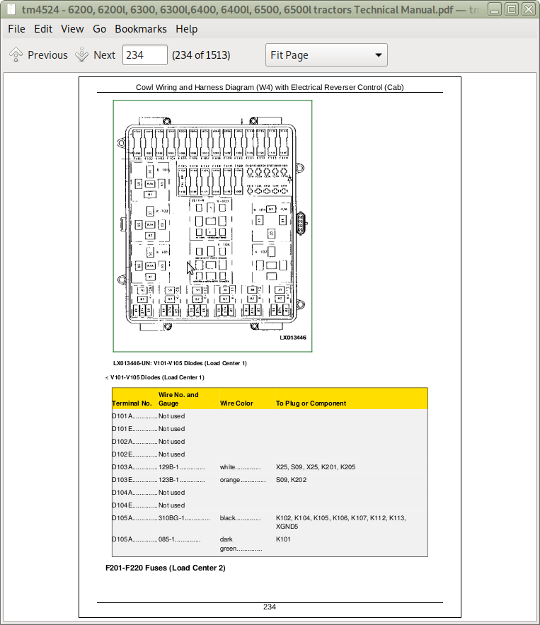
Cowl Wiring and Harness Diagram (W4) with Electrical Reverser Control (Cab)
Transmission Wiring Harness (AL112509; W20) (Cab)
Back-Up Alarm Wiring Harness (AL81580; W25) (Cab)
Back-Up Alarm Wiring Harness (AL113003; W26) (Cab)
Cab Roof Wiring Harness (AL110051; W11) from serial No. 135716 - 183107
Cab Roof Wiring Harness (AL112968; W11) from serial No. 183108
Worklight Wiring Harness (AL83139; W18) (Cab)
Cab Lighting Wiring Harnesses (W21, W22), Low-clearance cab
Wiper Wiring Harnesses( W23, W24), Low-clearance cab
Circuit Board of Instrument Unit and Plug Arrangement (Without Digital Control) (Cab)
Circuit Board of Instrument Unit and Plug Arrangement (With Digital Control) (Cab)
Group 10A: System Diagrams, 2-Post ROPS
Fuses (ROPS)
Part Designations in Functional Schematic, Wiring and Harness Diagrams (ROPS)
Section Designations in Functional Schematic (ROPS)
Harness Designation in Wiring Diagram (ROPS)
Functional Schematic (Complete Tractor-ROPS)
Engine Wiring Harness Diagram (W3; W2; W1) and Component Location up to Tractor Serial No. 116858 (ROPS)
Engine Wiring Harness Diagram (W3; W14) and Component Location from Tractor Serial No. 116859 (ROPS)
Cowl Wiring and Harness Diagram (W4; W9) and Component Location, Standard Version (Rops)
Cowl Wiring and Harness Diagram (W4; W9) and Component Location, Low Profile Version (ROPS)
Transmission Wiring and Harness Diagram and Component Location up to Serial No. 178178 (AL70819, W13) (ROPS)
Transmission Wiring and Harness Diagram and Component Location from Serial No. 178179 (AL111539, W13) (ROPS)
Back-Up Alarm Wiring Harness (AL81580; W25) (ROPS)
Back-Up Alarm Wiring Harness (AL113003; W26) (ROPS)
Circuit Board of Instrument Unit and Plug Arrangement (Standard Version) (ROPS)
Group 15: Sub-System Diagnostics, Cab
Special or Essential Tools
Specifications
SE1-Starting Motor and Charging Circuit (Cab) - Functional and Diagnostic Schematic
SE1-Starting Motor and Charging Circuit (Cab) - Component Checks
SE2-Instrument Unit and Lighting (Cab) - Functional and Diagnostic Schematic
SE2-Instrument Unit and Lighting (Cab) - Voltage Checks
SE3-Display Unit (Cab) - Functional and Diagnostic Schematic
SE3-Display Unit (Cab) - Voltage Checks
SE5-Horn (Cab) - Functional and Diagnostic Schematic
SE5-Horn (Cab) - Voltage Checks
SE6-Cigarette Lighter and Operator’s Seat (Cab) - Functional and DiagnosticSchematic
SE6-Cigarette Lighter and Operator’s Seat (Cab) - Voltage Checks
SE8-Rear PTO (Cab) - Functional and Diagnostic Schematic
SE8-Rear PTO (Cab) - Voltage Checks
SE9-Front Wheel Drive (Cab) - Functional and Diagnostic Schematic
SE9-Front Wheel Drive (Cab) - Voltage Checks
SE10-Differential Lock (Cab) - Functional and Diagnostic Schematic
SE10-Differential Lock (Cab) - Voltage Checks
SE12-Hazard Warning Flasher and Turn Signal Lights (Cab) - Functional and Diagnostic Schematic
SE12-Hazard Warning Flasher and Turn Signal Lights (Cab) - Voltage Checks
SE13-Lights (Cab) - Functional and Diagnostic Schematic
SE13-Lights (Cab) - Voltage Checks
SE14-Work Lights (Cab) - Functional and Diagnostic Schematic
SE14-Work Lights (Cab) - Voltage Checks
SE15-3-Terminal, 7-Terminal and Front Loader Power Outlet Sockets (Cab) - Functional and Diagnostic Schematic
SE15- 3 Terminal, 7 Terminal and Front-Loader Power Outlet Sockets (Cab) - Voltage Checks
SE16-Radio, Dome and Console Lights (Cab) - Functional and Diagnostic Schematic
SE16-Radio, Dome and Console Lights (Cab) - Voltage Checks
SE17-Blower and Air Conditioning System (Cab) - Functional and Diagnostic Schematic
SE17-Blower and Air Conditioning System - Voltage Checks
SE18-Windshield Wipers and Washers (Cab) - Functional and Diagnostic Schematic
SE18-Windshield Wipers and Washer (Cab) - Voltage Checks
SE19-Clutch Cooling (Cab) - Functional and Diagnostic Schematic
SE19-Clutch Cooling (Cab) - Voltage Checks
SE20-Beacon Light (Cab) - Functional and Diagnostic Schematic
SE20-Beacon Light (Cab) - Voltage Checks
SE21-Electronic Rockshaft Control (Cab) - Functional and Diagnostic Schematic
SE24-Back-Up Alarm (Cab) - Functional and Diagnostic Schematic
SE24-Back-Up Alarm (Cab) - Voltage Checks
SE25-Electrical Reverser Control (Cab) - Functional and Diagnostic Schematic
Group 15A: Sub-System Diagnostics, 2-Post ROPS
Special or Essential Tools
Specifications
SE1-Starting Motor and Charging Circuit (Rops) - Functional and Diagnostic Schematic
SE1-Starting Motor and Charging Circuit (Rops) - Component Checks
SE2-Instrument Unit and Lighting (ROPS) - Functional and Diagnostic Schematic
SE2-Instrument Unit and Lighting (ROPS) - Voltage Checks
SE3-Display Unit (ROPS) - Functional and Diagnostic Schematic
SE3-Display Unit (ROPS) - Voltage Checks
SE5-Horn (ROPS) - Functional and Diagnostic Schematic
SE5-Horn (ROPS) - Voltage Checks
SE8-Rear PTO (ROPS) - Functional and Diagnostic Schematic
SE8-Rear PTO (ROPS) - Voltage Checks
SE9-Front Wheel Drive (ROPS) - Functional and Diagnostic Schematic
SE9-Front Wheel Drive (ROPS) - Voltage Checks
SE10-Differential Lock (ROPS) - Functional and Diagnostic Schematic
SE10-Differential Lock (ROPS) - Voltage Checks
SE12-Hazard Warning Flasher and Turn Signal Lights (ROPS) - Functional and Diagnostic Schematic - Low Profile Version
SE12-Hazard Warning Flasher and Turn Signal Lights - Voltage Checks
SE13-Lights (ROPS) - Functional and Diagnostic Schematic
SE13-Lights (ROPS) - Voltage Checks
SE14-Work Lights (ROPS) - Functional and Diagnostic Schematic
SE14-Work Lights (ROPS) - Voltage Checks
SE15- 3 Terminal, 7 Terminal and Front-Loader Power Outlet Sockets (ROPS) - Functional and Diagnostic Schematic
SE15- 3 Terminal, 7 Terminal and Front-Loader Power Outlet Sockets (ROPS) - Voltage Checks
SE19-Clutch Cooling (ROPS) - Functional and Diagnostic Schematic
SE19-Clutch Cooling (ROPS) - Voltage Checks
SE21-Electronic Rockshaft Control (ROPS), Functional and Diagnostic Schematic
SE24-Back-Up Alarm (ROPS) - Functional and Diagnostic Schematic
SE24-Back-Up Alarm (ROPS) - Voltage Checks
Group 20: References
Battery Specifications
Battery Operation
Check Battery Electrolyte Level and Terminals
Procedure for Testing Batteries
Diagnose Battery Malfunctions
Starting With a Booster Battery
Section 250: Syncroplus Transmission
Group 05: Operational Checks
Checking if Clutch Separates Properly
Checking Clutch for Slippage
Checking Slip Phase of Clutch
Checking the Transmission
Checking Neutral Start Switch
Group 10: System Diagnosis
Explanation of System Diagnosis
Safety Precautions
Special or Essential Tools
Specifications
Heating Up Hydraulic Oil
Connecting JT07115 Hydraulic Test Kit
Layout of Test Ports and Sending Units
Preliminary Checks
Checking Gear and Range Engagement
Checking Clutch Operation
Checking the Transmission Oil Filter
System (Engagement) Pressure Test
Adjusting System (Engagement) Pressure
Check Components Dependent on System (Engagement) Pressure
Checking the Filter Relief Valve
Testing the Engagement Override Valve and Clutch Pedal Valve
Checking the Modulation of the Clutch Pedal Valve
Checking the Lube Oil Pressure
Clutch Cooling System Test (Up to Tractor Serial No. 109779)
Clutch Cooling System Test (From Tractor Serial No. 109780)
Measuring the Flow Rate
Checking the Cooler Relief Valve
Group 15: System Tests
Special or Essential Tools
Specifications
Checking Gear and Range Engagement
Range Transmission Linkage Test
Adjusting Range Transmission Linkage
Gear Transmission Linkage Test
Adjusting Shift Linkage at Gear Transmission
Adjusting Neutral Start Switch
Checking Neutral Start Switch
Adjusting the Shift Linkage
Adjusting Parking Lock
Clutch Pedal Adjustment
Group 20: Theory of Operation - Syncroplus Transmission
Layout of 12-Speed Transmission
Layout of 12-Speed Transmission With Creeper
Lubrication System
Shift Operation
Synchronization
Transmission Circuit - Theory of Operation
Group 20A: Theory of Operation - Perma Clutch II
Components
Clutch Design
Power Flow, Clutch Pedal Depressed
Power Flow, Clutch Pedal Not Depressed
Transmission Oil Pump - Theory of Operation
Hydraulic Circuit Diagram
Description of Valves
Other Transmission Oil Circuit Components
Over-Speed Relief and Air-Suction Valves - Theory of Operation
Clutch Pedal Valve and Engagement Override Valve,Theory of Operation-EngineOn, Clutch Pedal Not Depressed Since Engine Has Been Started
Clutch Pedal Valve and Engagement Override Valve,Theory of Operation-Engine On, Clutch Pedal Depressed
Clutch Pedal Valve and Engagement Override Valve, Theory of Operation-Engine On, Clutch Pedal in Process of Being Released
Clutch Cooling, Theory of Operation-Engine On, Clutch Pedalin Process of Being Released
Clutch Cooling, Theory of Operation-Engine On, Clutch Almost Fully Engaged
Clutch Cooling, Theory of Operation -Engine On, Clutch Engaged
Clutch Cooling, Theory of Operation -Engine On, Clutch in Process of Disengagement
Clutch Cooling, Theory of Operation -Engine On, Clutch Disengaged
Clutch Cooling, Theory of Operation -Engine On, Clutch Only Briefly Disengaged
Pressure Regulating Valve and Filter Relief Valve,Theory of Operation-NormalOperation (Transmission Oil Filter Clean)
Pressure Regulating Valve and Filter Relief Valve, Theory of Operation-Transmission Oil Filter Clogged
Pressure Regulating Valve and Filter Relief Valve, Theory of Operation-Transmission Oil Filter Completely Clogged
Cooler Relief Valve - Theory of Operation
Lube Relief Valve - Theory of Operation
Group 20B: Theory of Operation - Gear Transmission
Gear Transmission Design
Power Flow in 1st Gear
Power Flow in 2nd Gear
Power Flow in 3rd Gear
Power Flow in Reverse Gear
Neutral Start Switch
Group 20C: Theory of Operation - Creeper Transmission
Layout of Creeper Transmission
Power Flow With Creeper Disengaged
Power Flow With Creeper Engaged
Group 20D: Theory Of Operation - Range Transmission
Layout
Power Flow, Range A
Power Flow, Range B
Power Flow, Range C
Power Flow, Range D
Parking Lock
Section 255: Powrquad Transmission
Group 05: Operational Checks
Operational Checks - Before You Start
Group 10: System Diagnosis
Use Step-By-Step Hydraulic Diagnostic Charts
Special or Essential Tools
Service Equipment and Tools
Other Material
Observe Safety Precautions
Avoid High-Pressure Fluids
Connecting the Performance Monitor
Operating the Performance Monitor
Diagnostic Program
List of Addresses
Diagnosis
1 Connecting the Performance Monitor
2 Commencing the Program
3 Calling Up and Cancelling Service Codes
4 Carrying Out a Test Drive
List of Service Codes
Description of Service Codes
Service Code RCU 015
Service Code RCU 017
Service Code RCU 025
Service Code RCU 027
Service Code RCU 029
Service Code RCU 031
Service Code RCU 032
Service Code RCU 034
Service Code RCU 040
Service Code RCU 041
Service Code RCU 042
Service Code RCU 043
Service Code RCU 044
Service Code RCU 045
Service Code RCU 047
Service Code RCU 048
Service Code RCU 051
Service Code RCU 053
Service Code RCU 055
Service Code RCU 056
Service Code RCU 057
Service Code RCU 058
Service Code RCU 064
Service Code RCU 065
Service Code RCU 067
5 Calling Up Diagnostic Addresses
List of Diagnostic Addresses
Performing Diagnosis
Address RCU 02
Address RCU 03
Address RCU 04
Address RCU 05
Address RCU 06
Address RCU 07
7 Calling Up RCU Calibration Addresses
8 Calling Up RCU Identification Addresses
Adjust for Correct Pressure and Temperature References
Shortened Diagnostic Procedure
Powrquad Transmission Test
Summary of Transmission Testing
Lube Relief Valve Stuck Open
Transmission Oil Pump Air Leak Check
Clutch and Brake Element Air Leak Check Using a Blow Gun
Transmission Control Valve Housing Gasket
Transmission Slippage
PTO Clutch Drag
Hydraulics Fluid Over-Heating
Other Malfunctions
Group 15: Adjustments
Adjusting the Forward/Reverse Linkage (With Mechanical Reverser Control)
Adjusting the Shift Linkage and Parking Lock (Previous Version)
Adjusting the Shift Linkage and Parking Lock (Latest Version), With Reverser Control on Switch Console
Adjusting the Shift Linkage and Parking Lock (Latest Version), With Reverser Control on Steering Column
Clutch Pedal Adjustment (Up to Tractor Serial No. 130420)
Clutch Pedal Adjustment (From Tractor Serial No. 130421)
Group 20: Theory of Operation - Powrquad Transmission
Components of Powrquad Transmission
Powrquad Housings
Planetary Operation
Air Pump
Transmission Oil Pump
Clutch Oil Manifold
Reverse Brake Housing
Forward/Reverse Controls
Hydraulic Circuit Diagram - Mechanical Reverser Control (Older Tractor Series)
Component Layout - Mechanical Reverser Control (Older Tractor Series)
Hydraulic Circuit Diagram - Mechanical Reverser Control (Latest Tractor Series)
Hydraulic Circuit Diagram - Electrical Reverser Control
Filter Relief Valve
Pressure Regulating Valve
Forward-Reverse Modulation
EOV Circuit (With Mechanical Reverser Control)
Theory Of Operation - Electrical Reverser Control
Reverse Drive Lever
Park Switch
Valve Housing on Powrquad Module
Relays
Reverser Control Unit (RCU)
Detail of Hydraulic Circuit Diagram (Simplified)
Speed Control Circuit
Speed Modulation
Clutch Cooling Components
Oil Cooler System
Low-Pressure Clutch Cooling Valve
High-Pressure Clutch Cooling Valve
FWD-REV Cooling Control Valve
Clutch Pedal Control of Cooling Flow:
Cooler and Lube Circuits
Module Lube
Module Lube Flow Paths
Clutch Cooling Circuit Operation
Oil Cooler
Test Ports and Sending Units - With Mechanical Reverser Control
Test Ports and Sending Units - With Electrical Reverser Control
Section 256: Drive Systems (Without Transmission)
Group 05: Operational Checks
Checking Rear PTO
Group 10: System Diagnosis
Front Wheel Drive
Differential
Hydraulic Pump Drive
Final Drives
Rear PTO
Group 15: System Tests
Safety Precautions
Special or Essential Tools
Specifications
Heating Up Hydraulic Oil
Testing Operating Pressure of Fwd Clutch
Testing Operating Pressure of Hydraulic Differential Lock
Testing Rear PTO
Testing Lube Pressure of Fwd Clutch, Differential Lock and PTO
Group 20A: Theory of Operation - Front-Wheel Drive Clutch
Layout (Up to Transmission Serial No. 114447)
Oil and Power Flows With Front Wheel Drive Engaged
Oil and Power Flows With Front Wheel Drive Disengaged
Layout (Transmission Serial No. 114448 to 161066)
Oil and Power Flows With Front Wheel Drive Engaged
Oil and Power Flows With Front Wheel Drive Disengaged
Layout (From Transmission Serial No. 161067)
Oil and Power Flows With Front-Wheel Drive Engaged
Oil and Power Flows With Front-Wheel Drive Disengaged
Group 20B: Theory of Operation - Differential
Layout
Power Flow When Moving Straight Ahead
Power Flow When Cornering
Oil Flow With Differential Lock Engaged
Oil Flow With Differential Lock Disengaged
Group 20C: Theory of Operation - Final Drives
Description
Group 20D: Theory of Operation - Rear PTO Options
Description of Rear PTO Options
PTO Modulating Valve and Solenoid Valve
Operation of PTO Clutch and Brake
PTO Power Flow (540 RPM)
PTO Power Flow (540/1000 RPM, Reversible)
Section 260: Steering and Brakes
Group 05: Operational Checks
Checking the Steering
Checking the Brakes
Group 10: System Diagnosis
Hydrostatic Steering
Hydraulic Brakes
Group 15: System Tests
Special or Essential Tools
Specifications
Testing Leaf Springs of Steering Valve
Checking Steering System for External Leakage
Checking Steering System for Internal Leakage
Checking Steering Unit
Steering Valve Hydraulic Connections
Testing and Adjusting Shock Valves
Checking Brake System
Checking Brakes for Air in the System
Checking Brakes for External Leakage
Checking Brake Valve for Internal Leakage
Adjusting Brake Pedals
Bleeding the Brakes
Checking Brake Piston Travel
Adjusting the Stop Light Switch
Checking Rear Brakes
Group 20: Theory of Operation (Complete System)
Description
Group 20A: Hydrostatic Steering
Description of Steering Valve
Operation of Metering Unit
Oil Flow in Steering System
Oil Flow - Neutral Position
Oil Flow - Emergency Steering
Group 20B: Hydraulic Brakes
Brake Valve Layout
Operation
Brake Valve - Sectional View
Hydraulic Circuit Diagram
Oil Flow During Brake Application
Rear Brake Operation
Section 270: Hydraulic System
Group 05: Operational Checks
Operational Checks
Operational Checks on Rockshaft Control
Group 10: System Diagnosis
Explanation of System Diagnosis
Safety Precautions
Special or Essential Tools
Connecting Testers to Test Ports
Heating Up Hydraulic Oil
Specifications
Test Sequence
Information on System Diagnosis
Hydraulic Test Record
Group 15: System Tests
Explanation of the Hydraulic Tests
Safety Precautions
Special or Essential Tools
Service Equipment and Tools
Heating Up Hydraulic Oil
Lube Oil Pressure of Charge Pump
Checking and Adjusting System Pressure of Hydraulic Pump
Adjusting the Load Sense Valve on the Hydraulic Pump
Checking Load Sense Pressure
Checking the Load Sense Valve
Pressure Difference (Dynamic)
Causes of Internal Leakage
Arrangement of Shuttle Valves
Hydraulic System Response to a Missing Shuttle Valve
Diagnosing Faults at the Selective Control Valves
Check for Leaks at Valve Spools
Diagnosing Faults at Independent Control Valves
Checking Pressure Relief Valve of Rockshaft
Adjusting the Power Beyond Application Valve
Adjusting the Power Beyond Application Valve
Hydraulic Pump
Charge Pump
Checking, Calibrating and Adjusting the Rockshaft Control
List of Diagnostic and Calibration Procedures
Hitch Troubleshooting Tips
Checking With the Performance Monitor
Checking on Tractors With Dual Gauge Plus Dash Not possible from tractor serial no. 126575 to 132999
Abbreviations Used in the Display
Identification of Hitch Controls
Test Sequence
Identification of Electronic Control Unit (HCU)
Address 03 (AL78061) System Voltage
Address 04 (AL78061) Raising Valve Command
Address 05 (AL78061) Lowering Valve Command
Address 06 (AL78061) Supply Voltage For Potentiometer And Position Sensor
Address 07 (AL78061) Supply Voltage For Draft Sensors
Address 08 (AL78061) LH Draft Sensor Output Voltage
Address 09 (AL78061) RH Draft Sensor Output Voltage
Address 10 (AL78061) Load/Depth Control Potentiometer Output Voltage
Address 11 (AL78061) Hitch Height Control Potentiometer Output Voltage
Address 12 (AL78061) Position Sensor output voltage
Address 13 (AL78061) Raise Limit Potentiometer Output Voltage
Address 14 (AL78061) Rate Of Drop Potentiometer Output Voltage
Address 15 (AL78061) Remote Control Switch Position
Address 16 (AL78061) Voltage of Raise/Lower Rocker Switch
Address 19 (AL78061) Stepper Motor Position
Address 03 (HCU AL81198, AL110388, AL112325 And AL116824) Voltage of Raise/Lower Rocker Switch
Address 04 (HCU AL81198, AL110388, AL112325 and AL116824) LH Draft Sensor Output Voltage
Address 05 (HCU AL81198, AL110388, AL112325 and AL116824) RH Draft Sensor Output Voltage
Address 06 (HCU AL81198, AL110388, AL112325 and AL116824) Load/Depth Control Potentiometer Output Voltage
Address 07 (HCU AL81198, AL110388, AL112325 and AL116824) Hitch Height Control Potentiometer Output Voltage
Address 08 (HCU AL81198, AL110388, AL112325 and AL116824) Position Sensor Output Voltage
Address 09 (HCU AL81198, AL110388, AL112325 and AL116824) Raise Limit Potentiometer Output Voltage
Address 10 (HCU AL81198, AL110388, AL112325 and AL116824) Rate Of Drop Potentiometer Output Voltage
Address 11 (HCU AL81198, AL110388, AL112325 and AL116824) Remote Control Switch In Raising Position
Address 12 (HCU AL81198, AL110388, AL112325 and AL116824) Remote Control Switch In Lowering Position
Address 13 (HCU AL81198, AL110388, AL112325 and AL116824) Supply Voltage For Potentiometer And Position Sensor
Address 14 (HCU AL81198, AL110388, AL112325 and AL116824) Supply Voltage For Draft Sensors
Address 16 (HCU AL81198, AL110388, AL112325 and AL116824) Stepper Motor Position
Address 17 (HCU AL81198, AL110388, AL112325 and AL116824) Raise/Lower Valve Command
Address 18 (HCU AL81198, AL110388, AL112325 and AL116824) System Voltage
Calibration Procedure with HCU AL78061
CalibrationWith performance monitor -Brief Instructions for HCU AL78061
Calibration Procedure with HCUs AL81198, AL110388 and AL112325
Calibration - Brief Instructions for Control Units AL81198, AL110388 and AL112325
Checking the Stepper Motor and Rockshaft Valve
Centering the Stepper Motor
Checking Depth to Which Raising and Lowering Valves are Screwed In
Checking and Adjusting the Position Sensor
Checking and Adjusting the Draft Sensor
Procedure With Service Code 050
Group 20: Hydraulic System
Hydraulic Symbols (ISO 1219)
Hydraulics - A Description
Hydraulic System - Theory of Operation
Symbolic Representation of Hydraulic System
Hydraulic System - Schematic View
Hydraulic System - Three-Dimensional View
Group 20A: Charge Pump
Charge Pump - Description and Theory of Operation
Group 20B: Hydraulic Pump
Description of Hydraulic Pump
Location of Oil Lines
Pump Operation
Operating Modes
Group 20C: Hydraulic System Valves
Hydraulic Oil Filter With Filter Relief Valve
Oil Cooler
Primary Filter
Description of Shuttle Valves
Shuttle Valves - Theory of Operation
Main Block With Inlet Priority Valve
Inlet Priority Valve - Theory of Operation
Power Beyond Valve
Group 20D: Rockshaft and Lift Cylinders
Description of Rockshaft
Rockshaft Control - Theory of Operation
Rockshaft Valve - Theory of Operation
Position Sensor
Draft Sensor
Operation Unit
Hitch Control Unit (HCU)
Direct Control of Rockshaft
Group 20E: Selective Control Valves and Couplers
Selective Control Valves
200 Series Selective Control Valve- Neutral
200 Series Selective Control Valve-Extend
200 Series Selective Control Valve- Retract
200 Series Selective Control Valve-Float
300 Series Selective Control Valve Operation- Neutral
300 Series Selective Control Valve - Extend
300 Series Selective Control Valve- Retract
300 Series Selective Control Valve- Float
Couplers
Group 20F: Independent Control Valve
Description
Independent Control Valve - Sectional View
Oil Flow Through the Independent Control Valve
Section 290: Operator’s Station
Group 05: Operational Checks
A/C System Operational Checks
Results of Operational Checks
Group 10A: Air Conditioning - System Diagnosis
Safety at Work
Handling Refrigerant
Safety Equipment
In an Emergency
Storage of Refrigerant Containers
R134A Refrigerant
Important Note
Service Equipment and Tools
Other Material
Specifications
A/C System Diagnosis
Group 10B: Ventilation and Heater - System Diagnosis
Diagnosing Faults at Ventilation and Heater
Group 10C: Operator’s Seat - System Diagnosis
Diagnosis, MSG95 Operator’s Seat
Group 20A: Air Conditioning System - Theory Of Operation
Principle of Heat Exchange
R134A Refrigerant
Layout of Refrigerant Circuit
Description of How Refrigerant Circuit Functions
Description of How Refrigerant Circuit Functions
Compressor
Condenser
Receiver-Drier
Expansion Valve
Thermostat Switch
Evaporator
Temperature Selection Knob and Compressor Switch
Group 20B: Ventilation and Heater - Theory of Operation
Ventilation and Heater
Section 299: Special Tools (Dealer-Fabricated)
Group 05: Special Tools (Dealer-Fabricated)
DFRW2-Needle Valve Test Hose Assembly
DFRW85-Reverse Brake Test Plate
John Deere Tractors 6200, 6200L, 6300, 6300L, 6400, 6400L, 6500, 6500L Diagnosis and Tests Service Technical Manual (TM4524)
![]()