
John Deere Tractors 6110R, 6120R, 6130R, 6135R, 6145R, 6155R, 6175R, 6195R, 6215R Diagnosis and Tests Service Technical Manual (TM406719)
Complete Diagnosis & Tests Technical Manual with electrical wiring diagrams for John Deere Tractors 6110R, 6120R, 6130R, 6135R, 6145R, 6155R, 6175R, 6195R, 6215R, 6155RH, with all the service information to maintain, diagnose, and rebuild like professional mechanics.
John Deere 6R L0 (Engine 4045UXXXXXX) (Final Tier 4) Tractors 6110R, 6120R, 6130R, 6135R, 6145R, 6155R, 6155RH, 6175R, 6195R and 6215R workshop Diagnosis & Tests technical manual includes:
* Numbered table of contents easy to use so that you can find the information you need fast.
* Detailed sub-steps expand on repair procedure information
* Numbered instructions guide you through every repair procedure step by step.
* Troubleshooting and electrical service procedures are combined with detailed wiring diagrams for ease of use.
* Notes, cautions and warnings throughout each chapter pinpoint critical information.
* Bold figure number help you quickly match illustrations with instructions.
* Detailed illustrations, drawings and photos guide you through every procedure.
* Enlarged inset helps you identify and examine parts in detail.
tm406719 - Tractors 6110R to 6215R Diagnostics Technical Manual (Worldwide Edition).pdf
tm406719 - Tractors 6110R to 6215R Diagnostics Technical Manual (Worldwide Edition).epub
Total Pages: 12,920 pages
File Format: PDF/EPUB/MOBI/AZW (PC/Mac/Android/Kindle/iPhone/iPad; bookmarked, ToC, Searchable, Printable)
Language: English
MAIN SECTIONS
Foreword
Fuse and Relay Layout depending on Serial Number
General Information
Safety Information
General References
Diagnostic Trouble Codes
AIC Control Software
ATC Control Software
CCU Control Software
CLC Control Software
CSC Control Software
CRU Control Software
CSM Control Software
ECU Control Software
EIC Control Software
ETC Control Software
FCC Control Software
GPM Control Software
HCC Control Software
ICA Control Software
JDL Control Software
OIC Control Software
PAP Control Software
PDU Control Software
PL1 Control Software
PL2 Control Software
PL3 Control Software
PL4 Control Software
PLC Control Software
PTA Control Software
PTD Control Software
PTF Control Software
PTQ Control Software
RLC Control Software
RPM Control Software
RPT Control Software
SCC Control Software
SCO Control Software
SFA Control Software
SMV Control Software
TEC Control Software
TEI Control Software
TIA Control Software
TID Control Software
TIQ Control Software
VLC Control Software
VTI Control Software
XMC Control Software
XSC Control Software
Observable Symptoms and System Diagnostics
Engine
Fuel, Air Intake and Cooling Systems
Electrical System
Electronic Control Units
Drive Train (without Transmission)
AutoPowr™/IVT™ Transmission
DirectDrive Transmission
PowrQuad™ Transmission
Steering
Brakes
Hydraulic System
Machine-Specific Systems
Suspension Systems
Operator`s Cab
Engine
Exhaust Aftertreatment System, Theory of Operation
Tests and Adjustments
Fuel, Air Intake and Cooling Systems
General Information
Fuel System, Theory of Operation
Air Intake System, Theory of Operation
Cooling System, Theory of Operation
Charge Air Circuit, Theory of Operation
Cold-Weather Starting System, Theory of Operation
DEF Cooling Circuit, Theory of Operation
Fuel, Air Intake, and Cooling Systems - Schematics
Fuel, Air Intake, and Cooling Systems - Tests and Adjustments
Fuel, Air Intake, and Cooling Systems - Component Information
Fuel System, Component Information
Cooling System, Component Information
Charge Air Circuit, Component Information
Cold-Weather Starting System, Component Information
Electrical System
Electrical System - General Information
Electrical System - Theory of Operation
Electrical System - Schematics
Starter Motor and Charging Circuit
Voltage Converter
Lights
Worklight
Dome Light
Turn-Signal Lights
Operator`s Seat
Acoustic Alarm
Windshield and Rear Window Wipers
Heater / Ventilation / Air conditioning
Power Outlet Sockets
Radio
Electrical Outside Mirrors
Accessories
TEC Control Software and ISOBUS
AutoTrac™
Radar
JDLink™/Service ADVISOR™ Remote
Electronic Engine Control
Immobilizer
Fuel System
PowrQuad™ Transmission
AutoPowr™/IVT™ Transmission
DirectDrive Transmission
Differential Lock
Front-Wheel Drive
Rear PTO
Front PTO
Brakes
Rear Hitch
E-SCV Selective Control Valves
Suspended MFWD Axle
Cab Suspension
Electro-Hydraulic Pick-Up Hitch (E-PUH)
Front Loader
Front Hitch
Display
Cab Switch Module
Video Cameras
LIN Bus Modules
BUS Systems
Ground Connections
Electronic Control Units
Electronic Control Units - General Information
Electronic Control Units - Interactive Tests and Calibrations
Electronic Control Units - Information on Programming
Electronic Control Units - Theory of Operation
Electronic Control Units - Diagnostic Schematics
Electronic Control Units - Tests and Adjustments
Immobilizer Control Unit
AIC Control Software
ATC Control Software
CCU Control Software
CLC Control Software
CRU Control Software
CSC Control Software
CSM Control Software (CommandARM™)
CSM Control Software
ECU Control Software
EIC Control Software
ETC Control Software
FCC Control Software
GPM Control Software
HCC Control Software
ICA Control Software
JDL Control Software
OIC Control Software
PAP Control Software
PDU Control Software
PL1 Control Software
PL2 Control Software
PL3 Control Software
PL4 Control Software
PLC Control Software
PTA Control Software
PTD Control Software
PTF Control Software
PTQ Control Software
RLC Control Software
RPM Control Software
RPT Control Software
SCC Control Software
SCO Control Software
SFA Control Software
SMV Control Software
TEC Control Software
TEI Control Software
TIA Control Software
TID Control Software
TIQ Control Software
VLC Control Software
VTI Control Software
XMC Control Software
XSC Control Software
Electrical Connectors, Wiring Harnesses, and Components
Electrical Connectors, Wiring Harnesses, and Components - General Information
Summary of Electrical Components and Harnesses
Electrical Components - Assemblies
Electrical Components - Sensors
Electrical Components - Various Devices and Equipment
Electrical Components - Fuses, Relays, and Diodes
Electrical Components - Power Supply and Alternator
Electrical Components - Control and Signal Devices
Electrical Components - Electrical Motors
Electrical Components - Resistors
Electrical Components - Switches
Wiring Harnesses
Connector
Ground Points
Electrical Components - Solenoid Valves and Solenoids
Electrical Components - Other
Drive Train (without Transmission)
Drive Train (without Transmission) - Operational Checks
Drive Train (without Transmission) - Theory of Operation
Drive Train (without Transmission) - Tests and Adjustments
AutoPowr™/IVT™ Transmission
AutoPowr™/IVT™ Transmission - General Information
AutoPowr™/IVT™ Transmission - Operational Checks
AutoPowr™/IVT™ Transmission - Theory of Operation
AutoPowr™/IVT™ Transmission - Hydraulic Schematics
AutoPowr™/IVT™ Transmission - Tests and Adjustments
PowrQuad™ Transmission
PowrQuad™ Transmission - General Information
PowrQuad™ Transmission - Operational Checks
PowrQuad™ Transmission - Theory of Operation
PowrQuad™ Transmission - Hydraulic Schematic
PowrQuad™ Transmission - Tests and Adjustments
DirectDrive Transmission
DirectDrive Transmission - General Information
DirectDrive Transmission - Operational Checks
DirectDrive Transmission - Theory of Operation
DirectDrive Transmission - Hydraulic Schematic
DirectDrive Transmission - Tests and Adjustments
Drive Train - Component Information
Drive Train (without Transmission) - Component Information
AutoPowr™/IVT™ Transmission - Component Information
PowrQuad™ Transmission - Component Information
Steering
Steering - General Information
Steering - Operational Checks
Steering - Theory of Operation
Steering - Tests and Adjustments
Brakes
Brakes - General Information
Brakes - Operational Checks
Brakes - Theory of Operation
Brakes - Schematics
Brakes - Tests and Adjustments
Steering and Brakes - Component Information
Steering - Component Information
Brakes - Component Information
Hydraulic System
Hydraulic System - General Information
Hydraulic System - Operational Checks
Hydraulic System - Theory of Operation
Oil Filter, Additional Oil Reservoir, Charge Pump and Hydraulic Pump - Theory of Operation
Rear Hitch - Theory of Operation
Front Hitch - Theory of Operation
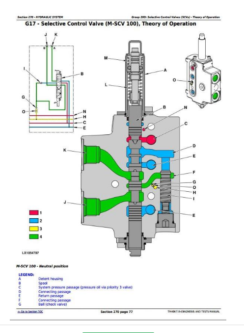
Selective Control Valves (SCVs) - Theory of Operation
Hydraulic System - Schematics
Hydraulic System - Tests and Adjustments
Hydraulic System - Component Information
Hydraulic System - Component Information
Machine-Specific Systems
Machine-Specific Systems - Operational Checks
Machine-Specific Systems - Theory of Operation
Machine-Specific Systems - Electrical System Diagrams
Machine-Specific Systems - Tests and Adjustments
Suspension Systems
Suspension Systems - Operational Checks
Suspended Front-Wheel Drive Axle - Theory of Operation
Cab Suspension - Theory of Operation
Suspended Front-Wheel Drive Axle - Schematics
Cab Suspension - Schematics
Suspended Front-Wheel Drive Axle - Tests and Adjustments
Cab Suspension - Tests and Adjustments
Machine-Specific Systems and Suspension Systems - Component Information
Suspended Front-Wheel Drive Axle - Component Information
Cab Suspension - Component Information
Machine-Specific Systems - Component Information
Operator`s Cab
Operator`s Cab - Operational Checks
Operator`s Cab - Theory of Operation
Operator`s Cab - Tests and Adjustments
Operator`s Cab - Component Information
Air-Conditioning System/Automatic Air-Conditioning Control - Component Information
Special Tools
General Information
tm406719 - Tractors 6110R to 6215R Diagnostics -: (Worldwide Edition)
Table of Contents
Foreword
Fuse and Relay Layout depending on Serial Number
Information on Serial Numbers and Content of CIU 2016 Improvement Program
MY15, MY16 and MY17 (Model Identification)Tractor Models of the 6R, FT4 Series
Section 210: General Information
Group 05: Safety Measures
General Information - Safety - Summary of References
Recognize Safety Information
Understand Signal Words
Follow Safety Instructions
Prevent Machine Runaway
Operating the Tractor Safely
Operating the Loader Tractor Safely
Passenger Seat
Use Safety Lights and Devices
Towing Trailers/Implements Safely (Mass)
Use Caution On Slopes and Uneven Terrain
Freeing a Mired Machine
Avoid Backover Accidents
Handle Fluids Safely—Avoid Fires
Handling Batteries Safely
Prepare for Emergencies
Avoid High-Pressure Fluids
Service Cooling System Safely
Remove Paint Before Welding or Heating
Avoid Heating Near Pressurized Fluid Lines
Work In Ventilated Area
Avoid Contact with Agricultural Chemicals
Handle Agricultural Chemicals Safely
Stay Clear of Rotating Drivelines
Wear Protective Clothing
Protect Against Noise
Practice Safe Maintenance
Avoid Hot Exhaust
Exhaust Filter Cleaning
Clean Exhaust Filter Safely
Read Operator Manuals for ISOBUS Implements
Use Steps and Handholds Correctly
Use Seat Belt Properly
Park Machine Safely
Use Proper Lifting Equipment
Construct Dealer-Made Tools Safely
Support Machine Properly
Work in Clean Area
Illuminate Work Area Safely
Service Machines Safely
Service Accumulator Systems Safely
Service Tires Safely
Use Proper Tools
Service Front-Wheel Drive Tractor Safely
Avoid Eye Contact With Radar
Keep ROPS Installed Properly
Replace Safety Signs
Replace Safety Signs
Dispose of Waste Properly
Live With Safety
Safety Measures on Electronic Control Units
Servicing Electronic Control Units
Welding Near Electronic Control Units
Keep Electronic Control Unit Connectors Clean
Safety Instructions for Replacing a Halogen Bulb
Safety Instructions for Replacing Xenon (HID) Bulbs and Ballast Units
Safety Instructions for Replacing LED Worklights
Group 10: General References
General Information - General References, Summary of References
Trademarks
Hydraulic Designators
Electrical Designators
General Information - Inch Bolt and Cap Screws, Torque Values
General Information - Metric Bolt and Cap Screws, Torque Values
General Information - Hydraulic System Inch Fittings, Torque Values
General Information - Hydraulic System Metric Fittings, Torque Values
General Information - Electrical System, Component Identification Table
General Information - Electrical System, How to Read a Diagnostic Schematic
General Information - Electrical System, Lead Numbers and Color Codes
General Information - Electrical System, Symbols in Schematic, Wiring and Harness Diagrams
General Information - Electrical System, Check the Connectors
General Information - Electrical System, Approach to Tabular Diagnostic Procedures
General Information - Electrical System, Troubleshooting Unsolved Problems
General Information - Electrical System, Worksheet for Circuit/Harness Test
General Information - Electrical System, Visual Check
General - Electrical System, Faults and Circuit Tests
General - Electrical System, Test for Open Circuit under Load
General Information - Electrical System, Seven-Step Test Procedure
General Information - Hydraulic System, Symbols in Circuit Diagrams
General - Regions and Country Versions
Section 211: Diagnostic Trouble Codes
Group AIC: AIC Control Software
AIC 000158.03 - Supply Voltage (ELX) Too High
AIC 000158.04 - Supply Voltage (ELX) Too Low
AIC 000168.03 - Supply Voltage (BAT) Too High
AIC 000168.04 - Supply Voltage (BAT) Too Low
AIC 000628.02 - Control Software Internal Fault
AIC 000628.12 - Control Software Internal Fault
AIC 000629.12 - Control Software Internal Fault
AIC 000639.12 - Vehicle CAN Bus (500 kBd), High Error Rate
AIC 000639.14 - Vehicle CAN Bus (500 kBd), Very High Error Rate
AIC 002007.09 - Incorrect CAN Bus Message, Information from RPT Control Software
AIC 002036.09 - Incorrect CAN Bus Message, Information from SCC Control Software
AIC 003509.03 - 5-Volt Supply Voltage 1, Voltage Too High
AIC 003509.04 - 5-Volt Supply Voltage 1, Voltage Too Low
AIC 003509.06 - 5-Volt Supply Voltage 1, Current Too High
AIC 003510.03 - 5-Volt Supply Voltage 2, Voltage Too High
AIC 003510.04 - 5-Volt Supply Voltage 2, Voltage Too Low
AIC 003510.06 - 5-Volt Supply Voltage 2, Current Too High
AIC 176865.02 - Remote Control Switch for Rear PTO, Malfunction
AIC 516315.09 - Incorrect LIN Bus Message, Information from LIN Bus Module (Position H)
AIC 516316.06 - 12-Volt Supply Voltage, Current Too High
AIC 516317.06 - 12-Volt Supply Voltage 2, Current Too High
AIC 516446.09 - LIN Bus Message Cannot Be Received, Information from LIN Bus Module (Positions F and G)
AIC 516461.02 - Multi-Function Lever Out of Range
AIC 520257.02 - Auto-Mode Switch Fault
AIC 520285.02 - Transport Lock/Hitch Dampening Button Fault
AIC 520285.03 - Transport Lock/Hitch Dampening Button, Voltage Too High
AIC 520285.11 - Transport Lock/Hitch Dampening Button Fault
AIC 520286.02 - Quick Raise/Lower Switch Fault
AIC 520286.04 - Quick Raise/Lower Switch, Voltage Too Low
AIC 520286.11 - Quick Raise/Lower Switch Fault
AIC 520425.07 - Received CAN Bus Messages, High Error Rate
AIC 520426.07 - Transmitted CAN Bus Messages, High Error Rate
AIC 520542.03 - Vehicle CAN Bus (500 kBd), Voltage Too High
AIC 520543.04 - Vehicle CAN Bus (500 kBd), Voltage Too Low
AIC 520870.02 - Control Software Internal Fault
AIC 520871.02 - Control Software Internal Fault
AIC 520872.02 - Control Software Internal Fault
AIC 521274.09 - Incorrect LIN Bus 1 Message, Information from LIN Bus Module (Position D or H)
AIC 521275.09 - Incorrect LIN Bus 2 Message, Information from LIN Bus Module (Position E or M)
AIC 521276.09 - Incorrect LIN Bus 3 Message, Information from LIN Bus Module (Position K or P)
AIC 521277.09 - Incorrect LIN Bus 4 Message, Information from LIN Bus Module (Position F or G)
AIC 521401.02 - Control Lever for SCV X (Front Hitch) Out of Range
AIC 521404.02 - Control Lever for SCV XI Out of Range
AIC 521405.02 - Control Lever for SCV XII Out of Range
AIC 521406.02 - Control Lever for SCV XIII Out of Range
AIC 521407.02 - Control Lever for SCV XIV Out of Range
AIC 521408.02 - Select Saved Operating Depth Button, Out Of Range
AIC 521409.02 - Multi-Function Lever, Switch 1 (Front Left) Out of Range
AIC 521410.02 - Multi-Function Lever, Switch 2 (Front Right) Out of Range
AIC 521411.02 - Multi-Function Lever, Switch 3 (Rear Left) Out of Range
AIC 521412.02 - Multi-Function Lever, Switch 4 (Rear Right) Out of Range
AIC 521413.02 - Multi-Function Lever, Switch 5 (Side Left) Out of Range
AIC 521421.02 - Incorrect LIN Bus Message from LIN Bus Module (Position M), Internal Fault
AIC 521422.02 - Incorrect LIN Bus Message from LIN Bus Module (Position M), Internal Fault
AIC 521465.09 - Incorrect LIN Bus Message, Information from LIN Bus Module (Position H)
AIC 521475.02 - Incorrect LIN Bus Message from LIN Bus Module (Position M), Internal Fault
AIC 521476.02 - Incorrect LIN Bus Message from LIN Bus Module (Position S), Internal Fault
AIC 521480.02 - Incorrect LIN Bus Message from LIN Bus Module (Position S), Internal Fault
AIC 521570.09 - Incorrect LIN Bus Message, Information from LIN Bus Module (Position S)
AIC 521571.09 - Incorrect LIN Bus Message, Information from LIN Bus Module (Position D)
AIC 521572.09 - Incorrect LIN Bus Message, Information from LIN Bus Module (Position E)
AIC 521573.09 - Incorrect LIN Bus Message, Information from LIN Bus Module (Position F)
AIC 521574.09 - Incorrect LIN Bus Message, Information from LIN Bus Module (Positions F and G)
AIC 521577.09 - Incorrect LIN Bus Message, Information from LIN Bus Module (Position P)
AIC 522077.11 - Switch for iTEC™ Program Selection, Fault
AIC 522189.02 - Switch for iTEC™ Program Selection, Fault
AIC 522189.03 - Switch for iTEC™ Program Selection, Voltage Too High
AIC 522189.04 - Switch for iTEC™ Program Selection, Voltage Too Low
AIC 522189.11 - Switch for iTEC™ Program Selection, Fault
AIC 522546.02 - Gear Selector Switch, Fault
AIC 522549.02 - Save/Delete Speed (Accelerator Pedal) Button Fault
AIC 522551.02 - Economy Mode Switch Fault
AIC 522553.02 - Cruise Control Switch Fault
AIC 522769.09 - Incorrect LIN Bus Message, Information from LIN Bus Module (Position M)
AIC 523343.02 - Switch on Multi-Function Lever, Fault
AIC 523343.03 - Switch on Multi-Function Lever, Voltage Too High
AIC 523343.04 - Switch on Multi-Function Lever, Voltage Too Low
AIC 523349.02 - AutoTrac™ Switch Fault
AIC 523349.03 - AutoTrac™ Switch, Voltage Too High
AIC 523349.04 - AutoTrac™ Switch, Voltage Too Low
AIC 523349.11 - AutoTrac™ Switch Fault
AIC 523652.09 - Incorrect LIN Bus Message, Information from LIN Bus Module (Position H)
AIC 523670.02 - Speed Control Lever Voltage Out of Range
AIC 523670.11 - Speed Control Lever Fault
AIC 523671.07 - Shift Unit (DirectDrive Transmission), Fault
AIC 523671.11 - Shift Unit (DirectDrive Transmission), Fault
AIC 523745.02 - Switch for iTEC™ Program Selection, Fault
AIC 523745.03 - Switch for iTEC™ Program Selection, Voltage Too High
AIC 523745.04 - Switch for iTEC™ Program Selection, Voltage Too Low
AIC 523745.11 - Switch for iTEC™ Program Selection, Fault
AIC 523775.02 - Multi-Function Lever Fault
AIC 523776.02 - Transport Lock Button of Multi-Function Lever, Fault
AIC 523804.02 - Multi-Function Lever, Left-Right Axis, Signal Out of Range
AIC 523804.03 - Multi-Function Lever, Left-Right Axis, Voltage Too High
AIC 523804.04 - Multi-Function Lever, Left-Right Axis, Voltage Too Low
AIC 523805.02 - Multi-Function Lever, Fore-Aft Axis, Signal Out of Range
AIC 523805.03 - Multi-Function Lever (E-ICV), Fore-Aft Axis, Voltage Too High
AIC 523805.04 - Multi-Function Lever, Fore-Aft Axis, Voltage Too Low
AIC 523923.02 - Control Lever for E-SCV I, Signal Out of Range
AIC 523923.03 - Control Lever for E-SCV I, Voltage Too High
AIC 523923.04 - Control Lever for E-SCV I, Voltage Too Low
AIC 523953.02 - Sensor Unit for Speed Control Lever, Signal Out of Range
AIC 523953.03 - Sensor Unit for Speed Control Lever, Voltage Too High
AIC 523953.04 - Sensor Unit for Speed Control Lever, Voltage Too Low
AIC 523954.11 - Sensor Unit for Speed Control Lever (Speed Wheel), Output Signals do Not Match
AIC 524017.31 - Reverse Drive Lever Supply Voltage Faulty
AIC 524019.31 - Reverse Drive Lever, Faulty Signal from Neutral Switch
AIC 524020.31 - INFORMATION FOR OPERATOR: Reverse Drive Lever in Position for Forward or Reverse Travel During Start-Up Procedure
AIC 524021.31 - Reverse Drive Lever Switches Actuated Simultaneously
AIC 524096.02 - Hand Throttle Potentiometer (AutoPowr™/IVT™ Transmission), Voltage Ratio Between Channel 1 and Channel 2 Not Correct
AIC 524096.03 - Hand Throttle Potentiometer, Voltage Too High
AIC 524096.04 - Hand Throttle Potentiometer, Voltage Too Low
AIC 524101.02 - Control Lever for E-SCV VI Faulty
AIC 524102.02 - Control Lever for E-SCV V Faulty
AIC 524103.02 - Control Lever for E-SCV IV Faulty
AIC 524104.02 - Control Lever for E-SCV III Faulty
AIC 524105.02 - Control Lever for E-SCV II Faulty
AIC 524212.02 - Depth-Setting Potentiometer Faulty
AIC 524216.02 - Front PTO Switch Faulty
AIC 524216.09 - Incorrect CAN Bus Message, Information from PTF Control Software
AIC 524224.02 - Rear PTO Switch Faulty
AIC 524224.09 - Incorrect CAN Bus Message, Information from RPT Control Software
Group ATC: ATC Control Software
ATC 000158.03 - Control Software, Supply Voltage (ELX) Too High
ATC 000158.04 - Control Software, Supply Voltage (ELX) Too Low
ATC 000170.03 - Sensor for Inside Air Temperature, Voltage Too High
ATC 000170.04 - Sensor for Inside Air Temperature, Voltage Too Low
ATC 000628.12 - Control Software, Internal Error
ATC 000630.02 - Control Software, Internal Error
ATC 000639.14 - Vehicle CAN Bus (500 kBd), Very High Error Rate
ATC 000871.03 - Refrigerant Pressure Sensor, Voltage Too High
ATC 000871.04 - Refrigerant Pressure Sensor, Voltage Too Low
ATC 000871.13 - Sensor for Refrigerant Pressure, Refrigerant Pressure Out of Range Low
ATC 000871.18 - Refrigerant Pressure Sensor, Malfunction
ATC 000876.03 - A/C Compressor Clutch, Voltage Too High
ATC 000876.04 - A/C Compressor Clutch, Voltage Too Low
ATC 000923.03 - Circulation Blower Motor On, Voltage Too High
ATC 000923.04 - Circulation Blower Motor On, Voltage Too Low
ATC 000923.12 - Circulation Blower Motor Internal Fault
ATC 001546.03 - Heater Valve (Potentiometer), Voltage Too High
ATC 001546.04 - Heater Valve (Potentiometer), Voltage Too Low
ATC 001547.03 - Sensor for Evaporator Core Temperature, Voltage Too High
ATC 001547.04 - Sensor for Evaporator Core Temperature, Voltage Too Low
ATC 001548.03 - Outlet Air Temperature Sensor, Voltage Too High
ATC 001548.04 - Outlet Air Temperature Sensor, Voltage Too Low
ATC 001549.03 - Heater Valve (Actuator), Voltage Too High
ATC 001549.04 - Heater Valve (Actuator), Voltage Too Low
ATC 001549.07 - Heater Valve, Fault
ATC 001549.13 - Heater Valve, Not Calibrated
ATC 001551.03 - Pressurizer Fan Motor for Pressure Inside Cab, Voltage Too High
ATC 001551.04 - Pressurizer Fan Motor for Pressure Inside Cab, Voltage Too Low
ATC 002000.09 - Incorrect CAN BUS Message, Coolant Temperature from ECU Control Software
ATC 002071.09 - Incorrect CAN BUS Message, Information from CCU Control Software
ATC 002139.09 - Incorrect CAN BUS Message, Information from CSM Control Software
ATC 003509.03 - 5-Volt Supply Voltage, Voltage Too High
ATC 003509.04 - 5-Volt Supply Voltage, Voltage Too Low
ATC 003509.06 - 5-V Supply Voltage, Current Too High
ATC 520870.02 - Control Software, Internal Error
ATC 520871.02 - Control Software, Internal Error
ATC 520872.02 - Control Software, Internal Error
ATC 523848.03 - Actuator for Air Distribution (Potentiometer), Voltage Too High
ATC 523848.04 - Actuator for Air Distribution (Potentiometer), Voltage Too Low
ATC 523848.05 - Actuator for Air Distribution, Current Too Low
ATC 523848.06 - Actuator for Air Distribution, Current Too High
ATC 523848.07 - Actuator for Air Distribution, Fault
ATC 523848.13 - Actuator for Air Distribution, Not Calibrated
ATC 524202.03 - Sensor for Ambient Air Temperature (Rear), Voltage Too High
ATC 524202.04 - Sensor for Ambient Air Temperature (Rear), Voltage Too Low
ATC 524203.03 - Sensor for Ambient Air Temperature (Front), Voltage Too High
ATC 524203.04 - Sensor for Ambient Air Temperature (Front), Voltage Too Low
ATC 524219.02 - Defog Sensor, Frequency Out of Valid Range
ATC 524219.03 - Defog Sensor, Voltage Too High
ATC 524219.04 - Defog Sensor, Voltage Too Low
Group CCU: CCU Control Software
CCU 000084.04 - Wheel Speed Sensor, Voltage Too Low
CCU 000084.05 - Wheel Speed Sensor, Current Too Low
CCU 000096.03 - Fuel Level Sensor Voltage Too High
CCU 000096.04 - Fuel Level Sensor Voltage Too Low
CCU 000096.17 - Fuel Level Too Low
CCU 000126.16 - Transmission Oil Filter Restricted
CCU 000158.03 - Control Software, Supply Voltage (ELX) Too High
CCU 000158.04 - Control Software, Supply Voltage (ELX) Too Low
CCU 000168.04 - Control Software, Supply Voltage (BAT) Too Low
CCU 000177.00 - Transmission Oil Temperature Very High
CCU 000177.03 - Transmission Oil Temperature Sensor, Voltage Too High
CCU 000177.04 - Transmission Oil Temperature Sensor, Voltage Too Low
CCU 000177.09 - CAN BUS Message Cannot Be Received, Information from PTA or PTD Control Software
CCU 000177.16 - Transmission Oil Temperature High
CCU 000177.19 - Transmission Oil Temperature Sensor, Fault
CCU 000177.31 - Transmission Oil Temperature Sensor, Fault
CCU 000190.09 - CAN BUS Message Cannot Be Received, Information from ECU Control Unit
CCU 000190.19 - Engine Speed Sensor Fault
CCU 000190.31 - Engine Speed Sensor Fault
CCU 000237.02 - VIN Information, Mismatch
CCU 000237.14 - VIN Information, System Disabled
CCU 000237.31 - VIN Information, Incorrect
CCU 000247.09 - Incorrect CAN Bus Message, CAN Message from ECU Control Unit
CCU 000247.19 - Operating Hours Fault
CCU 000247.31 - Operating Hours Fault
CCU 000569.03 - Differential Lock Solenoid Valve, Voltage Too High
CCU 000569.06 - Differential Lock Solenoid Valve, Current Too High
CCU 000628.02 - Control Software, Internal Error
CCU 000628.12 - Control Software, Internal Fault
CCU 000629.12 - Control Software, Internal Error
CCU 000630.14 - Control Software, Internal Error
CCU 000639.12 - Vehicle CAN Bus (500 kBd), High Error Rate
CCU 000639.14 - Vehicle CAN Bus (500 kBd), Very High Error Rate
CCU 000959.09 - Incorrect CAN Bus Message, CAN Message from VTV Control Unit
CCU 001058.03 - Pressure Switch for Air Brake System, Voltage Too High
CCU 001058.04 - Pressure Switch for Air Brake System, Voltage Too Low
CCU 001058.16 - INFORMATION FOR OPERATOR: Pressure Switch for Air-Brake System Is Not Activated (Pressure Too High)
CCU 001058.18 - INFORMATION FOR OPERATOR: Pressure Switch for Air-Brake System Is Not Activated (Pressure Too Low)
CCU 001069.02 - INFORMATION FOR OPERATOR: Tire Circumference Not or Incorrectly Calibrated
CCU 001231.12 - Implement CAN Bus, High Error Rate
CCU 001231.14 - Implement CAN Bus, Very High Error Rate
CCU 001713.02 - Hydraulic Oil Filter Sensor, Fault
CCU 001713.15 - Hydraulic Oil Filter Dirty
CCU 001713.16 - Hydraulic Oil Filter Blocked
CCU 001865.09 - Incorrect CAN Bus Message, Information from OIC Control Software
CCU 002000.09 - Incorrect CAN Bus Message, Information from ECU Control Unit
CCU 002003.09 - Incorrect CAN Bus Message, Information from PTA or PTD Control Software
CCU 002005.09 - Incorrect CAN Bus Message, Information from TIA Control Software
CCU 002019.09 - Incorrect CAN BUS Message, Information from XSC Control Software
CCU 002049.09 - Incorrect CAN Bus Message, Information from OIC Control Software
CCU 002139.09 - Incorrect CAN BUS Message, Information from CSM Control Software
CCU 002145.09 - Incorrect CAN Bus Message, Information from FCC Control Software
CCU 002198.09 - Incorrect CAN Bus Message, Information from XMA Control Software
CCU 002221.09 - Incorrect CAN Bus Message, Information from PLC Control Software
CCU 003353.07 - Alternator Fault
CCU 003353.09 - Alternator Fault
CCU 003353.14 - Alternator Fault
CCU 003353.15 - Alternator, Temperature Too High
CCU 003510.03 - 5-Volt Supply Voltage, Voltage Too High
CCU 003510.04 - 5-Volt Power Supply, Voltage Too Low
CCU 003510.06 - 5-Volt Supply Voltage, Current Too High
CCU 003597.03 - 12-Volt Supply Voltage, Voltage Too High
CCU 003597.06 - 12 V Supply Voltage, Current Too High
CCU 005016.06 - 12 V Supply Voltage, Current Too High
CCU 516123.09 - Incorrect LIN Bus Message, LIN Message from Battery Cut-Off Relay
CCU 516123.14 - Battery Cut-Off Relay Mismatch
CCU 516123.31 - Battery Cut-Off Relay Fault
CCU 520425.07 - Received CAN Bus Messages, High Error Rate
CCU 520426.07 - Transmitted CAN Bus Messages, High Error Rate
CCU 520542.03 - Vehicle CAN Bus (500 kBd), Voltage Too High
CCU 520543.04 - Vehicle CAN Bus (500 kBd), Voltage Too Low
CCU 520870.02 - Control Software, Internal Error
CCU 521979.06 - Keep-Alive Signal, Current Too High
CCU 522451.02 - Wheel Angle Sensor, Voltages in Channel 1 and Channel 2 Not in Correct Ratio
CCU 522451.03 - Wheel Angle Sensor Channel 2, Voltage Too High
CCU 522451.04 - Wheel Angle Sensor Channel 2, Voltage Too Low
CCU 522578.09 - CAN Bus Message Cannot Be Received, Information from CSM Control Software
CCU 522578.19 - Switch for Selecting Front-Wheel Drive as Brake Assistance, Malfunction
CCU 522578.31 - Switch for Selecting Front-Wheel Drive as Brake Assistance, Malfunction
CCU 522580.09 - CAN Bus Message Cannot Be Received, Information from CSM Control Software
CCU 522580.19 - Switch for Automatic Mode of Front-Wheel Drive, Malfunction
CCU 522580.31 - Switch for Automatic Mode of Front-Wheel Drive, Malfunction
CCU 522581.09 - CAN Bus Message Cannot Be Received, Information from CSM Control Software
CCU 522581.19 - Switch for Switching On Front-Wheel Drive, Malfunction
CCU 522581.31 - Switch for Switching On Front-Wheel Drive, Malfunction
CCU 523219.04 - Differential Lock Solenoid Valve, Voltage Too Low
CCU 523666.03 - Control Software, Supply Voltage (BAT) Too High
CCU 523666.04 - Control Software, Supply Voltage (BAT) Too Low
CCU 523769.31 - Front-Wheel Drive Switch, Fault
CCU 523789.13 - Wheel Angle Sensor Not Calibrated
CCU 523826.03 - Wheel Angle Sensor Channel 1, Voltage Too High
CCU 523826.04 - Wheel Angle Sensor Channel 1, Voltage Too Low
CCU 523826.09 - Incorrect CAN BUS Message, CAN Message (Steering Angle Sensor) from XSC Control Software
CCU 524157.09 - Incorrect CAN Bus Message, CAN Message from OIC Control Software
CCU 524157.19 - Brake Pedal, Right Signal, Malfunction
CCU 524157.31 - Brake Pedal, Right Signal, Malfunction
CCU 524162.09 - Incorrect CAN Bus Message, CAN Message from OIC Control Software
CCU 524162.19 - Brake Pedal, Left Signal, Malfunction
CCU 524162.31 - Brake Pedal, Left Signal, Malfunction
CCU 524191.02 - INFORMATION FOR OPERATOR: Air-Brake System, Fault
CCU 524191.03 - Air Brake System Solenoid Valve Voltage Too High
CCU 524191.05 - Air Brake System Solenoid Valve Voltage Too Low
CCU 524191.06 - Air Brake System Solenoid Valve Current Too High
CCU 524191.19 - INFORMATION FOR OPERATOR: Air-Brake System, Fault
CCU 524218.09 - Incorrect CAN Bus Message, CAN Message from OIC Control Software
CCU 524218.19 - Park Lock Fault
CCU 524218.31 - Park Lock Fault
CCU 524223.03 - Differential Lock Switch, Fault
CCU 524235.03 - Front-Wheel Drive Solenoid Valve, Voltage Too High
CCU 524235.06 - Front-Wheel Drive Solenoid Valve, Current Too High
Group CLC: CLC Control Software
CLC 000444.06 - Control Software CLC, Current Too High
CLC 000628.02 - Control Software, Internal Error
CLC 000630.13 - Control Software, Internal Error
CLC 000639.14 - Vehicle CAN Bus (500 kBd), Very High Error Rate
CLC 000920.03 - Acoustic Alarm Voltage Too High
CLC 000920.06 - Acoustic Alarm Current Too High
CLC 001865.09 - Incorrect CAN Bus Message, Information from OIC Control Software
CLC 001877.06 - Implement Switch, Current Too High
CLC 001877.09 - Incorrect CAN Bus Message, Information from HCC Control Software
CLC 001877.19 - Hitch Control Fault
CLC 001877.31 - Hitch Control Fault
CLC 002000.09 - Incorrect CAN Bus Message, Information from ECU Control Unit
CLC 002025.09 - Incorrect CAN Bus Message, Information from ATC/ETC Control Software
CLC 002040.09 - Incorrect CAN Bus Message, Information from PDU Control Software
CLC 002049.09 - Incorrect CAN Bus Message, Information from OIC Control Software
CLC 002050.06 - Control Software, Current Too High
CLC 002055.09 - Incorrect CAN Bus Message, Information from RLC Control Software
CLC 002071.09 - Incorrect CAN BUS Message, Information from CCU Control Software
CLC 002140.09 - Incorrect CAN Bus Message, Information from AIC Control Software
CLC 002145.09 - Incorrect CAN Bus Message, Information from FCC Control Software
CLC 002240.09 - Incorrect CAN Bus Message, Information from TEC Control Software
CLC 002368.03 - Left Extra-Wide Vehicle Warning Light (ECE), Voltage Too High
CLC 002368.05 - Left Extra-Wide Vehicle Warning Light (ECE), Current Too Low
CLC 002368.06 - Left Extra-Wide Vehicle Warning Light (ECE), Current Too High
CLC 002370.03 - Right Extra-Wide Vehicle Warning Light (ECE), Voltage Too High
CLC 002370.05 - Right Extra-Wide Vehicle Warning Light (ECE), Current Too Low
CLC 002370.06 - Right Extra-Wide Vehicle Warning Light (ECE), Current Too High
CLC 002372.03 - Brake Light on Tractor, Voltage Too High
CLC 002372.05 - Brake Light on Tractor, Current Too Low
CLC 002372.06 - Brake Light on Tractor, Current Too High
CLC 002376.06 - Trailer Brake Light, Current Too High
CLC 002378.05 - Tail Light and Extra-Wide Vehicle Warning Light, Current Too Low
CLC 002378.06 - Tail Light and Extra-Wide Vehicle Warning Light, Current Too High
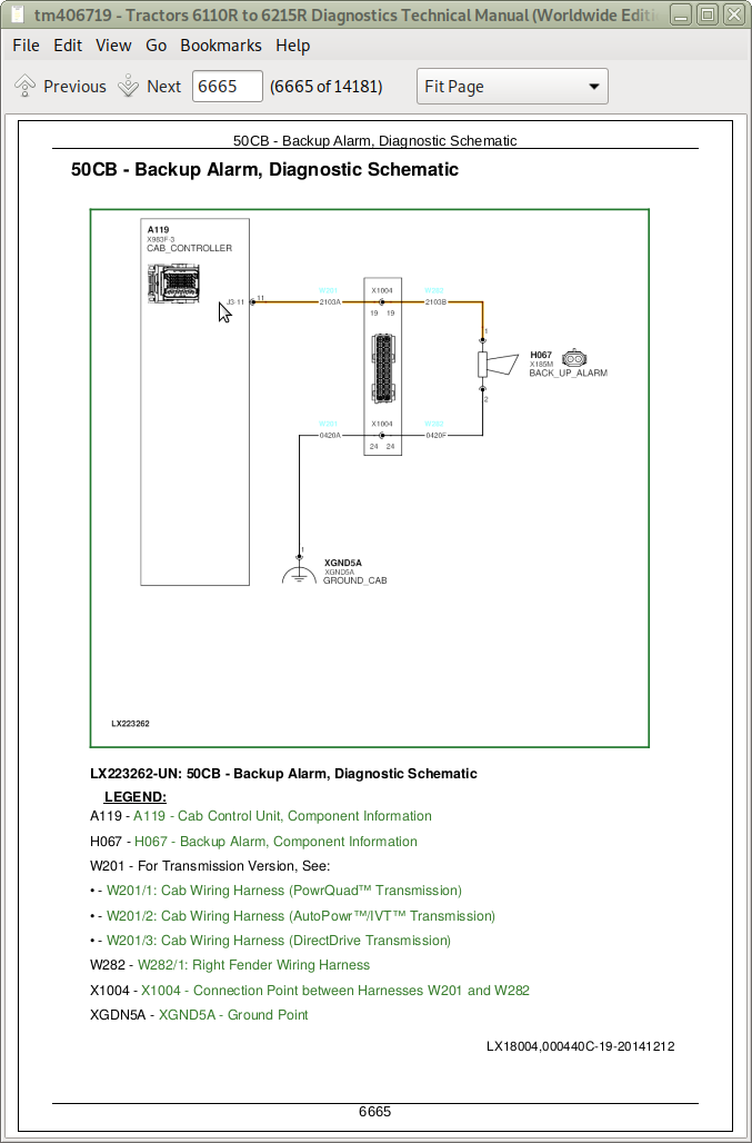
CLC 002392.03 - Back-Up Alarm, Voltage Too High
CLC 002392.06 - Back-Up Alarm, Current Too High
CLC 516676.09 - Incorrect CAN Bus Message, Information from HCC Control Software
CLC 516676.19 - Implement Switch Fault
CLC 516676.31 - Implement Switch Fault
CLC 520490.03 - Implement Supply Voltage, Voltage Too High
CLC 520490.06 - Implement Supply Voltage, Current Too High
CLC 520491.03 - Supply Voltage for a Control Unit on Implement, Voltage Too High
CLC 520491.06 - Supply Voltage for a Control Unit on Implement, Current Too High
CLC 520715.03 - Pressurizer Fan Motor for Pressure Inside Cab, Voltage Too High
CLC 520715.05 - Fan Motor for Pressure Inside Cab, Current Too Low
CLC 520715.06 - Fan Motor for Pressure Inside Cab, Current Too High
CLC 520870.02 - Control Software, Internal Error
CLC 521388.06 - Windshield Wiper (Home Position), Current Too High
CLC 521547.03 - Left Worklight on Rear of Fender, Voltage Too High
CLC 521547.06 - Left Worklight on Rear of Fender, Current Too High
CLC 521565.03 - Right Worklight on Rear of Fender, Voltage Too High
CLC 521565.06 - Right Worklight on Rear of Fender, Current Too High
CLC 521835.20 - Control Software CLC, Ground Contact Malfunction
CLC 522434.06 - Windshield Wiper (Slow), Current Too High
CLC 522435.06 - Windshield Wiper (Fast), Current Too High
CLC 522620.03 - Horn, Voltage Too High
CLC 522620.06 - Horn, Current Too High
CLC 522876.19 - CAN Bus Message, Fault
CLC 522876.31 - CAN Bus Message, Fault
CLC 524162.09 - CAN Bus Message Cannot be Received, Information from OIC Control Software
CLC 524259.00 - Cab Control Unit, Temperature Too High
CLC 524259.15 - Cab Control Unit, Temperature Too High
CLC 524259.16 - Cab Control Unit, Temperature Too High
Group CSC: CSC Control Software
CSC 000084.15 - Wheel Speed Detected During Calibration
CSC 000084.19 - Incorrect CAN Bus Message, Wheel Speed Signal Incorrect
CSC 000190.17 - Incorrect CAN Bus Message, Engine Speed Too Low
CSC 000190.19 - Incorrect CAN Bus Message, Engine Speed Not Detected
CSC 000574.19 - Incorrect CAN Bus Message, Enable Signal Not Detected or Incorrect
CSC 000629.12 - Control Software, Internal Error
CSC 000898.19 - Incorrect CAN Bus Message, Engine Speed Not Detected or Incorrect
CSC 002000.09 - Incorrect CAN Bus Message, Information from ECU Control Software
CSC 002003.09 - Incorrect CAN Bus Message, Information from TIA/TIQ Control Software
CSC 002005.09 - Incorrect CAN Bus Message, Information from TIQ Control Software
CSC 002006.09 - Incorrect CAN Bus Message, Information from EIC Control Software
CSC 002020.09 - Incorrect CAN Bus Message, Information from SFA Control Software
CSC 002049.09 - Incorrect CAN Bus Message, Information from OIC Control Software
CSC 002071.09 - Incorrect CAN Bus Message, Information from CCU Control Software
CSC 002145.09 - Incorrect CAN Bus Message, Information from FCC Control Software
CSC 003511.03 - 5-V Supply Voltage to CSC Sensors, Voltage Too High
CSC 003511.04 - 5-V Supply Voltage to CSC Sensors, Voltage Too Low
CSC 003511.06 - 5-V Supply Voltage to CSC Sensors, Current Too High
CSC 520425.07 - Received CAN Bus Messages, High Error Rate
CSC 520426.07 - Transmitted CAN Bus Messages, High Error Rate
CSC 520542.03 - Vehicle CAN Bus (500 kBd), Voltage Too High
CSC 520543.04 - Vehicle CAN Bus (500 kBd), Voltage Too Low
CSC 520870.02 - Control Software, Internal Error
CSC 520870.13 - Control Software Not or Incorrectly Calibrated
CSC 520871.02 - Control Software, Internal Error
CSC 520871.13 - Control Software, Internal Error
CSC 520892.02 - Control Software, Internal Error
CSC 522288.03 - Proportional Solenoid Valve for Cab Suspension, Voltage Too High
CSC 522288.05 - Proportional Solenoid Valve for Cab Suspension, Current Too Low
CSC 522288.06 - Proportional Solenoid Valve for Cab Suspension, Current Too High
CSC 522457.19 - Incorrect CAN Bus Message, Commanded Transmission Speed
CSC 522763.19 - Reverse Drive Lever, Fault
CSC 523666.03 - Supply Voltage of Rear Chassis Control Unit, Voltage Too High
CSC 523666.04 - Supply Voltage of Rear Chassis Control Unit, Voltage Too Low
CSC 523671.19 - Incorrect CAN Bus Message, Signal from Reverse Drive Lever
CSC 523948.03 - Solenoid Valve for Lowering Cab Suspension, Voltage Too High
CSC 523948.05 - Solenoid Valve for Lowering Cab Suspension, Current Too Low
CSC 523948.06 - Solenoid Valve for Lowering, Current Too High
CSC 523949.03 - Solenoid Valve for Raising, Voltage Too High
CSC 523949.05 - Solenoid Valve for Raising, Current Too Low
CSC 523949.06 - Solenoid Valve for Raising, Current Too High
CSC 523973.02 - Cab Position Out of Valid Range (2 - 3 V) During Calibration
CSC 523973.03 - Cab Suspension All the Way Up, Voltage Too High (During Calibration)
CSC 523973.04 - Cab Suspension All the Way Down, Voltage Too Low (During Calibration)
CSC 523973.07 - Cab Suspension Does Not Reach Level Position in Target Time, Fault
CSC 523973.10 - Cab Suspension Fails to Reach Level Position or End Stops in the Target Time During Calibration
CSC 523973.13 - Cab Suspension Sensor Not Calibrated Correctly
CSC 523973.14 - Cab Suspension Sensor Not Calibrated
CSC 523973.15 - Sensor for Cab Suspension at Bottom Stop, Incorrect Sensor Signal
CSC 523973.16 - Pressure Reduction, Lowest Position Not Reached, Fault
CSC 523973.17 - Cab Suspension All the Way Up During Calibration, Incorrect Sensor Signal
CSC 523973.18 - Bleeding (Cab Suspension), Level Position Not Reached
CSC 523973.31 - Cab Moves in Wrong Direction During Calibration
CSC 524157.19 - Incorrect CAN Bus Message, Right Brake Pedal
CSC 524162.19 - Incorrect CAN Bus Message, Left Brake Pedal
CSC 524165.19 - Incorrect CAN Bus Message, Clutch
CSC 524167.19 - Incorrect CAN Bus Message, Transmission
Group CRU: CRU Control Software
CRU 000168.03 - Control Software, Supply Voltage (BAT) Too High
CRU 000168.04 - Control Software, Supply Voltage (BAT) Too Low
CRU 000237.02 - VIN Information, Mismatch
CRU 000639.12 - Vehicle CAN Bus (500 kBd), High Error Rate
CRU 000639.14 - Vehicle CAN Bus (500 kBd), Very High Error Rate
CRU 002850.03 - Radio Antenna, Voltage Too High
CRU 002850.05 - Radio Antenna, Current Too Low
CRU 002850.06 - Radio Antenna, Current Too High
CRU 520194.02 - VIN Information, Mismatch
CRU 520772.12 - Control Software, Internal Fault
CRU 521156.12 - XM Satellite Radio, Fault
CRU 521780.06 - USB Connection, Current Too High
CRU 522453.12 - Control Software, Internal Fault
CRU 524259.00 - CD Drive, Temperature Too High
CRU 524259.31 - Radio, Temperature Too High
Group CSM: CSM Control Software
CSM 000168.04 - Control Software, Supply Voltage (BAT) Too Low
CSM 000628.02 - Control Software, Internal Error
CSM 000628.12 - Control Software, Internal Error
CSM 000629.12 - Control Software, Internal Error
CSM 000630.02 - Control Software, Internal Error
CSM 000639.12 - Vehicle CAN Bus (500 kBd), High Error Rate
CSM 000639.14 - Vehicle CAN Bus (500 kBd), Very High Error Rate
CSM 002875.04 - Hazard Warning Light Button, Voltage Too Low
CSM 520425.07 - Received CAN Bus Messages, High Error Rate
CSM 520426.07 - Transmitted CAN Bus Messages, High Error Rate
CSM 520542.03 - Vehicle CAN Bus (500 kBd), Voltage Too High
CSM 520543.04 - Vehicle CAN Bus (500 kBd), Voltage Too Low
CSM 521160.02 - Button for Volume Control (Lower Volume), Fault
CSM 521160.08 - Button for Volume Control (Lower Volume), Fault
CSM 521161.02 - Button for Volume Control (Raise Volume), Fault
CSM 521161.08 - Button for Volume Control (Raise Volume), Fault
CSM 521162.02 - Button for Previous Radio Station/Track, Fault
CSM 521162.08 - Button for Previous Radio Station/Track, Fault
CSM 521163.02 - Button for Next Radio Station/Track, Fault
CSM 521163.08 - Button for Next Radio Station/Track, Fault
CSM 521164.02 - Fan Control Button (+), Fault
CSM 521164.08 - Fan Control Button (+), Fault
CSM 521165.02 - Radio Mute Button, Fault
CSM 521165.08 - Radio Mute Button, Fault
CSM 521166.02 - Temperature Control Button (+), Fault
CSM 521166.08 - Temperature Control Button (+), Fault
CSM 521167.02 - Fan Control Button (-), Fault
CSM 521167.08 - Fan Control Button (-), Fault
CSM 521168.02 - Air Flow Distribution Button, Fault
CSM 521168.08 - Air Flow Distribution Button, Fault
CSM 521169.02 - Temperature Control Button (-), Fault
CSM 521169.08 - Temperature Control Button (-), Fault
CSM 521856.02 - Cancel Button (X Button), Fault
CSM 521856.08 - Cancel Button (X Button), Fault
CSM 522558.02 - Button for Switching the Differential Lock On and Off Manually, Fault
CSM 522558.08 - Button for Switching the Differential Lock On and Off Manually, Fault
CSM 522559.02 - Button for Switching the Differential Lock On and Off Automatically, Fault
CSM 522559.08 - Button for Switching the Differential Lock On and Off Automatically, Fault
CSM 522560.02 - Beacon Light Button, Fault
CSM 522560.08 - Beacon Light Button, Fault
CSM 522563.02 - Button for Light Combination 1 or 2, Fault
CSM 522563.08 - Button for Light Combination 1 or 2, Fault
CSM 522564.02 - ISOBUS (ISB) Button, Fault
CSM 522564.03 - ISOBUS (ISB) Button, Voltage Too High
CSM 522564.04 - ISOBUS (ISB) Button, Voltage Too Low
CSM 522564.08 - ISOBUS (ISB) Button, Fault
CSM 522565.02 - Button for Transport Lock (E-SCVs), Fault
CSM 522565.08 - Button for Transport Lock (E-SCVs), Fault
CSM 522566.02 - Front-Wheel Drive Button, Fault
CSM 522566.08 - Front-Wheel Drive Button, Fault
CSM 522567.02 - Button for Automatic Mode of Front-Wheel Drive, Fault
CSM 522567.08 - Button for Automatic Mode of Front-Wheel Drive, Fault
CSM 522568.02 - iTEC™ Menu Hotkey, Fault
CSM 522568.08 - Phone Menu Hotkey, Fault
CSM 522569.02 - Position 16 Hotkey, Fault
CSM 522569.08 - Climate Control Menu Hotkey, Fault
CSM 522570.02 - Rear PTO Menu Hotkey, Fault
CSM 522570.08 - Lights Menu Hotkey, Fault
CSM 522571.02 - Reconfigurable Controls Menu Hotkey, Fault
CSM 522571.08 - Position 14 Hotkey, Fault
CSM 522572.02 - Transmission Menu Hotkey, Fault
CSM 522572.08 - E-SCV Menu Hotkey, Fault
CSM 522573.02 - Climate Control Menu Hotkey, Fault
CSM 522573.08 - Audio Menu Hotkey, Fault
CSM 522574.02 - Engine Menu Hotkey, Fault
CSM 522574.08 - Reconfigurable Controls Menu Hotkey, Fault
CSM 522575.02 - Lights Menu Hotkey, Fault
CSM 522575.08 - iTEC™ Menu Hotkey, Fault
CSM 522576.02 - Rear Hitch Menu Hotkey, Fault
CSM 522576.08 - Rear Hitch Menu Hotkey, Fault
CSM 522577.02 - Audio Menu Hotkey, Fault
CSM 522577.08 - Position 6 Hotkey, Fault
CSM 522578.02 - E-SCV Menu Hotkey, Fault
CSM 522578.08 - Transmission Menu Hotkey, Fault
CSM 522579.02 - Phone Menu Hotkey, Fault
CSM 522579.08 - Rear PTO Menu Hotkey, Fault
CSM 522580.02 - Next RunPage Button, Fault
CSM 522580.08 - Next RunPage Button, Fault
CSM 522581.02 - Position 2 Hotkey, Fault
CSM 522581.08 - Engine Menu Hotkey, Fault
CSM 522770.09 - LIN Bus Message Cannot Be Received, Information from LIN Bus Module (Position W)
CSM 522771.09 - LIN Bus Message Cannot Be Received, Information from LIN Bus Module (Position K)
Group ECU: ECU Control Software
ECU 000027.03 - EGR Valve Position Signal Out of Range High
ECU 000027.04 - EGR Valve Position Signal Out of Range Low
ECU 000027.07 - EGR Valve Actuator Fault
ECU 000051.03 - Air Throttle Actuator Position Signal Out of Range High
ECU 000051.04 - Air Throttle Actuator Position Signal Out of Range Low
ECU 000051.07 - Air Throttle Actuator Fault
ECU 000051.14 - Air Throttle Actuator and EGR Valve Connectors Swapped
ECU 000094.03 - Low-Pressure Fuel Signal Out of Range High
ECU 000094.04 - Low-Pressure Fuel Signal Out of Range Low
ECU 000094.16 - Low-Pressure Fuel Signal Moderately High
ECU 000094.17 - Low-Pressure Fuel Signal Slightly Low
ECU 000094.18 - Low-Pressure Fuel Signal Moderately Low
ECU 000097.03 - Water-In-Fuel Signal Voltage Out of Range High
ECU 000097.04 - Water-In-Fuel Signal Voltage Out of Range Low
ECU 000097.16 - Water-In-Fuel Level Moderately High
ECU 000098.09 - Incorrect CAN Bus Message, Information from Engine Oil Level Sensor
ECU 000098.12 - Engine Oil Level Sensor, Fault
ECU 000100.01 - Engine Oil Pressure Signal Extremely Low
ECU 000100.02 - Engine Oil Pressure Faulty
ECU 000100.03 - Engine Oil Pressure Signal Out of Range High
ECU 000100.04 - Engine Oil Pressure Signal Out of Range Low
ECU 000100.18 - Engine Oil Pressure Moderately Low
ECU 000101.00 - Crankcase Pressure Signal Extremely High
ECU 000101.03 - Crankcase Pressure Signal Out of Range High
ECU 000101.04 - Crankcase Pressure Signal Out of Range Low
ECU 000101.06 - Engine Crankcase Pressure Signal Out of Range High
ECU 000101.16 - Crankcase Pressure Moderately High
ECU 000102.03 - Manifold Air Pressure Signal Out of Range High
ECU 000102.04 - Manifold Air Pressure Signal Out of Range Low
ECU 000102.07 - Manifold Air Pressure Sensor Signal Fault
ECU 000103.00 - VGT Speed Signal Extremely High
ECU 000103.02 - Turbocharger Speed Signal Invalid
ECU 000103.05 - Turbocharger Speed Sensor Resistance Too High
ECU 000105.00 - Manifold Air Temperature Extremely High
ECU 000105.03 - Manifold Air Temperature Sensor, Voltage Too High
ECU 000105.04 - Manifold Air Temperature Sensor, Voltage Too Low
ECU 000105.15 - Manifold Air Temperature Signal Slightly High
ECU 000105.16 - Manifold Air Temperature Signal Moderately High
ECU 000107.00 - Air Filter Pressure Differential Extremely High
ECU 000107.15 - Air Cleaner Pressure Differential Slightly High
ECU 000107.16 - Air Cleaner Pressure Differential Moderately High
ECU 000108.02 - Barometric Pressure Signal Invalid
ECU 000108.07 - Barometric Pressure Signal Mismatch
ECU 000109.01 - Coolant Pressure Signal Extremely Low
ECU 000109.03 - Coolant Pressure Signal Out of Range High
ECU 000109.04 - Coolant Pressure Signal Out of Range Low
ECU 000109.17 - Coolant Pressure Signal Slightly Low
ECU 000109.18 - Coolant Pressure Signal Moderately Low
ECU 000109.31 - Coolant Pressure Signal Fault
ECU 000110.00 - Coolant Temperature Signal Extremely High
ECU 000110.03 - Coolant Temperature Signal Too High
ECU 000110.04 - Coolant Temperature Signal Out of Range Low
ECU 000110.15 - Coolant Temperature Signal Slightly High
ECU 000110.16 - Coolant Temperature Signal Moderately High
ECU 000110.17 - Coolant Temperature Signal Slightly Low
ECU 000111.01 - Coolant Level Switch Activated at High Coolant Temperature
ECU 000111.07 - Coolant Level Switch Fault
ECU 000111.17 - Coolant Level Switch Activated
ECU 000111.18 - Coolant Level Switch Activated at Moderate Coolant Temperature
ECU 000152.12 - Control Software Internal Fault
ECU 000152.14 - Control Software Internal Fault
ECU 000152.16 - Control Software Internal Fault
ECU 000157.01 - Fuel Rail Pressure Signal Extremely Low
ECU 000157.02 - Fuel Rail Pressure Signal Invalid
ECU 000157.03 - Fuel Rail Pressure Signal Out of Range High
ECU 000157.04 - Fuel Rail Pressure Signal Out of Range Low
ECU 000157.12 - Fuel Rail Pressure Faulty
ECU 000157.16 - Fuel Rail Pressure Signal Moderately High
ECU 000157.17 - Fuel Rail Pressure Signal Slightly Low
ECU 000157.18 - Fuel Rail Pressure Signal Moderately Low
ECU 000158.12 - Control Software Internal Fault
ECU 000168.01 - Engine Control Unit, Supply Voltage (BAT) Too Low
ECU 000168.16 - Engine Control Unit, Supply Voltage (BAT) Moderately High
ECU 000168.17 - Engine Control Unit, Supply Voltage (BAT) Too Low
ECU 000168.18 - Engine Control Unit, Supply Voltage (BAT) Moderately Low
ECU 000174.00 - Fuel Temperature Signal Extremely High
ECU 000174.03 - Fuel Temperature Signal Out of Range High
ECU 000174.04 - Fuel Temperature Signal Out of Range Low
ECU 000174.16 - Fuel Temperature Signal Moderately High
ECU 000189.31 - Engine Speed Derate Condition Exists
ECU 000190.00 - Engine Speed Extremely High
ECU 000190.16 - Engine Speed Moderately High
ECU 000237.02 - VIN Information, Mismatch
ECU 000237.13 - VIN Information, Option Code Invalid
ECU 000237.31 - VIN Information, Incorrect
ECU 000412.00 - EGR Temperature Signal Extremely High
ECU 000412.03 - EGR Temperature Signal Out of Range High
ECU 000412.04 - EGR Temperature Signal Out of Range Low
ECU 000412.15 - EGR Temperature Signal Slightly High
ECU 000412.16 - EGR Temperature Signal Moderately High
ECU 000611.03 - Injection Valve Driver 1, Voltage Too High
ECU 000611.04 - Injection Valve Driver 1, Short To Ground
ECU 000612.03 - Injection Valve Driver 2, Voltage Too High
ECU 000612.04 - Injection Valve Driver 2, Short To Ground
ECU 000613.03 - Driver Of Fuel Pressure Control Valves, Voltage Too High
ECU 000613.04 - Driver Of Fuel Pressure Control Valves, Short To Ground
ECU 000613.31 - Driver Of Fuel Pressure Control Valves Faulty
ECU 000629.02 - Control Software Internal Fault
ECU 000629.12 - Control Software, Internal Fault
ECU 000629.13 - Control Software, Internal Fault
ECU 000629.14 - Control Software Internal Fault
ECU 000629.31 - Control Software Internal Fault
ECU 000636.02 - Camshaft Speed Signal Invalid
ECU 000636.05 - Camshaft Speed Sensor, Resistance Too High
ECU 000636.06 - Camshaft Speed Sensor, Resistance Too Low
ECU 000636.08 - Camshaft Speed Missing
ECU 000636.10 - Camshaft Speed Signal Rate of Change Abnormal
ECU 000637.02 - Crankshaft Speed Invalid
ECU 000637.05 - Crankshaft Speed Sensor, Resistance Too High
ECU 000637.06 - Crankshaft Speed Sensor, Resistance Too Low
ECU 000637.07 - Camshaft Speed and Crankshaft Speed Signals Out of Sync
ECU 000637.08 - Crankshaft Speed Missing
ECU 000637.10 - Crankshaft Speed Signal Rate of Change Abnormal
ECU 000641.00 - VGT Actuator Temperature Extremely High
ECU 000641.05 - Driver of VGT Actuator, Resistance Too High
ECU 000641.06 - Driver of VGT Actuator, Resistance Too Low
ECU 000641.07 - VGT Actuator Learned Value Error
ECU 000641.09 - CAN Bus Message Cannot Be Received, Information from VGT Actuator
ECU 000641.12 - VGT Actuator Internal Fault
ECU 000641.13 - VGT Actuator, Calibration Error
ECU 000641.16 - VGT Actuator Temperature Slightly High
ECU 000641.31 - VGT Actuator Supply Voltage Fault
ECU 000647.05 - Proportional Solenoid Valve for Charge Air Cooler Hydraulic Motor, Current Too Low
ECU 000647.06 - Proportional Solenoid Valve for Charge Air Cooler Hydraulic Motor, Current Too High
ECU 000651.02 - Part Number of Injector 1 Invalid
ECU 000651.05 - Injection Valve 1, Resistance Too High
ECU 000651.06 - Injection Valve 1, Resistance Too Low
ECU 000651.13 - Injection Valve 1, Calibration Error
ECU 000651.18 - Injection Valve 1 Fault
ECU 000652.02 - Part Number of Injector 2 Invalid
ECU 000652.05 - Injection Valve 2, Resistance Too High
ECU 000652.06 - Injection Valve 2, Resistance Too Low
ECU 000652.13 - Injection Valve 2, Calibration Error
ECU 000652.18 - Injection Valve 2 Fault
ECU 000653.02 - Part Number of Injector 3 Invalid
ECU 000653.05 - Injection Valve 3, Resistance Too High
ECU 000653.06 - Injection Valve 3, Resistance Too Low
ECU 000653.13 - Injection Valve 3, Calibration Error
ECU 000653.18 - Injection Valve 3 Fault
ECU 000654.02 - Part Number of Injector 4 Invalid
ECU 000654.05 - Injection Valve 4, Resistance Too High
ECU 000654.06 - Injection Valve 4, Resistance Too Low
ECU 000654.13 - Injection Valve 4, Calibration Error
ECU 000654.18 - Injection Valve 4 Fault
ECU 000655.02 - Part Number of Injector 5 Invalid
ECU 000655.05 - Injection Valve 5, Resistance Too High
ECU 000655.06 - Injection Valve 5, Resistance Too Low
ECU 000655.13 - Injection Valve 5, Calibration Error
ECU 000655.18 - Injection Valve 5 Fault
ECU 000656.02 - Part Number of Injector 6 Invalid
ECU 000656.05 - Injection Valve 6, Resistance Too High
ECU 000656.06 - Injection Valve 6, Resistance Too Low
ECU 000656.13 - Injection Valve 6, Calibration Error
ECU 000656.18 - Injection Valve 6 Fault
ECU 000676.05 - Relay for Electric Starting Aid, Current Too Low
ECU 000676.06 - Relay for Electric Starting Aid, Current Too High
ECU 000676.14 - Cold Start Aid Signal Received When Not Expected
ECU 000676.31 - Cold Start Aid Relay Signal Not Received When Expected
ECU 000970.31 - Engine Start Fault
ECU 001075.02 - Fuel Pump Fault
ECU 001075.04 - Fuel Pump, Voltage Too Low
ECU 001075.05 - Fuel Pump, Resistance Too High
ECU 001075.06 - Fuel Pump, Resistance Too Low
ECU 001075.09 - CAN Bus Message Cannot Be Received, Information from Fuel Pump
ECU 001075.12 - Fuel Pump Fault
ECU 001075.15 - Fuel Pump, Temperature Too High
ECU 001110.31 - Engine Protection Shutdown
ECU 001136.00 - Engine Control Unit, Temperature Too High
ECU 001136.02 - Engine Control Unit, Temperature Invalid
ECU 001136.16 - Engine Control Unit, Temperature Moderately High
ECU 001172.12 - Intake Air Temperature Fault
ECU 001176.07 - Intake Air Pressure Mismatch
ECU 001176.12 - Intake Air Pressure Fault
ECU 001180.00 - Calculated VGT Turbine Inlet Temperature Extremely High
ECU 001180.16 - Calculated VGT Turbine Inlet Temperature Moderately High
ECU 001209.03 - Exhaust Manifold Pressure Signal Out of Range High
ECU 001209.04 - Exhaust Manifold Pressure Signal Out of Range Low
ECU 001209.07 - Exhaust Manifold Pressure Mismatch
ECU 001321.05 - Engine Starter Solenoid Lockout Relay Circuit Has High Resistance
ECU 001321.06 - Engine Starter Solenoid Lockout Relay Circuit Has Low Resistance
ECU 001321.16 - ECU has Detected that the Starter has been Engaged Too Long
ECU 001322.31 - Engine Misfires Detected
ECU 001347.05 - Fuel Pressure Control Valve 1, Resistance Too High
ECU 001347.06 - Fuel Pressure Control Valve 1, Resistance Too Low
ECU 001347.07 - Control Valve 1 Fuel Pressure Deviation
ECU 001348.05 - Fuel Pressure Control Valve 2, Resistance Too High
ECU 001348.06 - Fuel Pressure Control Valve 2, Resistance Too Low
ECU 001351.05 - Compressor Clutch for Trailer Air Brakes, Current Too Low
ECU 001351.06 - Compressor Clutch for Trailer Air Brakes, Current Too High
ECU 001550.05 - A/C Compressor Clutch, Current Too Low
ECU 001550.06 - A/C Compressor Clutch, Current Too High
ECU 001569.31 - Engine in Derate Condition
ECU 001639.01 - Proportional Solenoid Valve for Charge Air Cooler, Speed Not Available
ECU 001639.16 - Proportional Solenoid Valve for Charge Air Cooler, Speed Moderately Increased
ECU 001639.18 - Proportional Solenoid Valve for Charge Air Cooler, Speed Low
ECU 001761.01 - DEF Tank Empty
ECU 001761.03 - DEF Tank Fluid Level Sensor, Voltage Too High
ECU 001761.04 - DEF Tank Fluid Level Sensor, Voltage Too Low
ECU 001761.17 - DEF Tank Fluid Level Moderately Low
ECU 001761.18 - DEF Tank Fluid Level Low
ECU 002006.09 - Incorrect CAN Bus Message, Information from EIC Control Software
ECU 002006.13 - VIN Information Mismatch
ECU 002006.14 - VIN Information Mismatch
ECU 002006.19 - VIN Information Mismatch
ECU 002025.09 - Incorrect CAN Bus Message, Information from ATC/ETC Control Software
ECU 002071.09 - Incorrect CAN Bus Message, Information from CCU Control Software
ECU 002629.03 - Compressor Outlet Temperature Signal Out Of Range High
ECU 002629.04 - Compressor Outlet Temperature Signal Out Of Range Low
ECU 002630.00 - Charge Air Cooler Outlet Temperature Signal Extremely High
ECU 002630.03 - Charge Air Cooler Outlet Temperature Signal Out of Range High
ECU 002630.04 - Charge Air Cooler Outlet Temperature Signal Out of Range Low
ECU 002630.15 - Charge Air Cooler Outlet Temperature Signal Slightly High
ECU 002630.16 - Charge Air Cooler Outlet Temperature Signal Moderately High
ECU 002659.01 - NOx Based EGR Flow Correction Extremely Low
ECU 002659.02 - EGR Flow Signal Invalid
ECU 002659.03 - EGR Flow Signal Out of Range High
ECU 002659.04 - EGR Flow Signal Out of Range Low
ECU 002659.14 - EGR Flow Signal Fault
ECU 002659.15 - EGR Flow Signal Moderately High
ECU 002659.17 - EGR Flow Signal Moderately Low
ECU 002659.18 - NOx Based EGR Flow Correction Moderately Low
ECU 002790.16 - Fixed Turbocharger Compressor Outlet Temperature Moderately High
ECU 002791.05 - EGR Valve Actuator, Current Too Low
ECU 002791.06 - EGR Valve Actuator, Current Too High
ECU 002791.07 - EGR Valve Actuator Fault
ECU 002791.13 - EGR Valve Actuator, Calibration Error
ECU 002795.03 - VGT Actuator, Voltage Too High
ECU 002795.04 - VGT Actuator, Voltage Too Low
ECU 002795.07 - VGT Actuator Fault
ECU 002795.10 - Calculated Rate of Change of VGT Actuator Abnormal
ECU 002795.13 - VGT Actuator, Calibration Error
ECU 002795.31 - VGT Actuator Fault
ECU 002797.03 - Injection Valve Supply Voltage 1, Voltage Too High
ECU 002797.05 - Injection Valve Supply Voltage 1, Resistance Too High
ECU 002797.06 - Injection Valve Supply Voltage 1, Resistance Too Low
ECU 002798.03 - Injection Valve Supply Voltage 2, Voltage Too High
ECU 002798.05 - Injection Valve Supply Voltage 2, Resistance Too High
ECU 002798.06 - Injection Valve Supply Voltage 2, Resistance Too Low
ECU 003031.03 - DEF Tank Fluid Temperature Signal Out of Range High
ECU 003031.04 - DEF Tank Fluid Temperature Sensor, Voltage Too Low
ECU 003031.12 - DEF Tank Fluid Tank Temperature Error
ECU 003216.09 - CAN Bus Message Cannot Be Received, Information from Aftertreatment Inlet NOx Sensor
ECU 003216.12 - Aftertreatment Inlet NOx Sensor Faulty
ECU 003216.14 - Aftertreatment Inlet NOx Sensor Faulty
ECU 003226.09 - CAN Bus Message Cannot Be Received, Information from Aftertreatment Outlet NOx Sensor
ECU 003226.12 - Aftertreatment Outlet NOx Sensor Faulty
ECU 003226.14 - Aftertreatment Outlet NOx Sensor Faulty
ECU 003246.00 - DPF Outlet Temperature Extremely High
ECU 003246.12 - DPF Outlet Temperature Fault
ECU 003251.00 - DPF Differential Pressure Sensor Fault
ECU 003251.02 - DPF Differential Pressure Signal Invalid
ECU 003251.03 - DPF Differential Pressure Signal Out of Range High
ECU 003251.04 - DPF Differential Pressure Signal Out of Range Low
ECU 003251.07 - DPF Differential Pressure Sensor Fault
ECU 003353.31 - Alternator Fault
ECU 003361.03 - DEF Dosing Injector Signal Out of Range High
ECU 003361.04 - DEF Dosing Injector Signal Out of Range Low
ECU 003361.05 - DEF Dosing Injector Circuit Has High Resistance
ECU 003361.06 - DEF Dosing Injector Circuit Has Low Resistance
ECU 003361.07 - DEF Dosing Injector Position Invalid
ECU 003361.31 - DEF Dosing Injector Active Without Injection
ECU 003464.05 - Air Throttle Actuator, Resistance Too High
ECU 003464.06 - Air Throttle Actuator, Resistance Too Low
ECU 003464.07 - Air Throttle Actuator Fault
ECU 003464.13 - Air Throttle Actuator Calibration Error
ECU 003465.05 - Air Throttle Actuator, Resistance Too High
ECU 003465.06 - Air Throttle Actuator, Resistance Too Low
ECU 003465.07 - Air Throttle Actuator Fault
ECU 003465.13 - Air Throttle Actuator Calibration Error
ECU 003473.03 - Actuator Signal Out of Range High
ECU 003473.04 - Actuator Signal Out of Range Low
ECU 003473.07 - Air Throttle Signal, Fault
ECU 003509.03 - Sensor Supply Voltage 1 Out of Range High
ECU 003509.04 - Sensor Supply Voltage 1 Out of Range Low
ECU 003510.03 - Sensor Supply Voltage 2 Out of Range High
ECU 003510.04 - Sensor Supply Voltage 2 Out of Range Low
ECU 003511.03 - Sensor Supply Voltage 3 Out of Range High
ECU 003511.04 - Sensor Supply Voltage 3 Out of Range Low
ECU 003512.03 - Sensor Supply Voltage 4 Out of Range High
ECU 003512.04 - Sensor Supply Voltage 4 Out of Range Low
ECU 003513.03 - Sensor Supply Voltage 5 Out of Range High
ECU 003513.04 - Sensor Supply Voltage 5 Out of Range Low
ECU 003514.03 - Sensor Supply Voltage 6 Out of Range High
ECU 003514.04 - Sensor Supply Voltage 6 Out of Range Low
ECU 003516.01 - Aftertreatment DEF Concentration Extremely Low
ECU 003516.07 - Aftertreatment DEF Concentration Sensor Obstructed
ECU 003516.09 - Aftertreatment DEF Concentration Sensor Loss of Communication
ECU 003516.12 - Aftertreatment DEF Concentration Sensor Error
ECU 003516.14 - Aftertreatment DEF Contaminated
ECU 003516.16 - Aftertreatment DEF Concentration Moderately High
ECU 003597.01 - Fuel Injector High Voltage Supply Extremely Low
ECU 003695.14 - Calculated Soot Level High and Regeneration Disabled
ECU 003517.07 - DEF Tank Fluid Level Sensor Obstructed
ECU 003517.12 - DEF Tank Fluid Level Error
ECU 003711.14 - Diesel Particulate Filter Active Regeneration Inhibited Due to Low Exhaust Gas Temperature
ECU 003711.31 - Diesel Particulate Filter Active Regeneration Inhibited Due to Low Exhaust Gas Temperature
ECU 003719.00 - Calculated Soot Level Extremely High
ECU 003719.10 - Calculated Soot Load Rate of Change Abnormal
ECU 003719.13 - Excessive DPF Recovery Attempts
ECU 003719.14 - Calculated Soot Level Extremely High
ECU 003719.15 - Calculated Soot Level Slightly High
ECU 003719.16 - Calculated Soot Level Moderately High
ECU 003720.15 - Calculated Ash Level Slightly High
ECU 003720.16 - Calculated Ash Level Moderately High
ECU 003936.00 - Calculated Unintended Combustibles in DPF Extremely High
ECU 003936.15 - Calculated Unintended Combustibles in DPF Slightly High
ECU 003936.16 - Calculated Unintended Combustibles in DPF Moderately High
ECU 004334.00 - DEF Dosing Unit Pressure Extremely High
ECU 004334.01 - DEF Dosing Unit Pressure Extremely Low
ECU 004334.03 - DEF Dosing Unit Signal Out of Range High
ECU 004334.04 - DEF Dosing Unit Signal Out of Range Low
ECU 004334.11 - DEF Dosing Unit Pressure Signal Fault
ECU 004334.16 - DEF Dosing Unit Pressure Moderately High
ECU 004334.18 - DEF Dosing Unit Pressure Moderately Low
ECU 004334.31 - DEF Dosing Unit Pressure Fault
ECU 004341.05 - DEF Dosing Unit Pressure Line Heater, Resistance Too High
ECU 004341.06 - DEF Dosing Unit Pressure Line Heater, Resistance Too Low
ECU 004343.05 - DEF Dosing Unit Return Line Heater, Resistance Too High
ECU 004343.06 - DEF Dosing Unit Return Line Heater, Resistance Too Low
ECU 004345.05 - DEF Dosing Unit Supply Line Heater, Resistance Too High
ECU 004345.06 - DEF Dosing Unit Supply Line Heater, Resistance Too Low
ECU 004360.07 - SCR Inlet Temperature Fault
ECU 004360.12 - SCR Inlet Temperature Faulty
ECU 004363.12 - SCR Outlet Temperature Faulty
ECU 004364.01 - Catalytic Converter Efficiency of SCR System Extremely Low
ECU 004364.17 - Catalytic Converter Efficiency of SCR System Slightly Low
ECU 004364.18 - Catalytic Converter Efficiency of SCR System Moderately Low
ECU 004366.05 - DEF Tank Heater Coolant Valve, Resistance Too High
ECU 004366.06 - DEF Tank Heater Coolant Valve, Resistance Too Low
ECU 004366.16 - DEF Tank Heater Coolant Control Valve is Stuck Open
ECU 004366.18 - DEF Tank Heater Coolant Control Valve is Stuck Closed
ECU 004376.05 - DEF Dosing Unit Reversing Valve, Resistance Too High
ECU 004376.06 - DEF Dosing Unit Reversing Valve, Resistance Too Low
ECU 004376.14 - DEF Dosing System Powerdown Fault
ECU 004490.12 - Intake Air Humidity Fault
ECU 004765.00 - DOC Inlet Temperature Extremely High
ECU 004765.12 - DOC Inlet Temperature Fault
ECU 004766.12 - DOC Outlet Temperature Fault
ECU 004766.15 - DOC Outlet Temperature Slightly High
ECU 004766.16 - DOC Outlet Temperature Moderately High
ECU 004766.17 - DOC Outlet Temperature Slightly Low
ECU 004766.18 - DOC Outlet Temperature Moderately Low
ECU 004795.13 - Exhaust Filter Calibration Fault
ECU 004795.31 - DPF Missing
ECU 005018.00 - Calculated Unintended Combustibles in DOC Extremely High
ECU 005018.16 - Calculated Unintended Combustibles in DOC Moderately High
ECU 005125.03 - Sensor Supply Voltage 7 Out of Range High
ECU 005125.04 - Sensor Supply Voltage 7 Out of Range Low
ECU 005126.03 - Sensor Supply Voltage 8 Out of Range High
ECU 005126.04 - Sensor Supply Voltage 8 Out of Range Low
ECU 005127.03 - Sensor Supply Voltage 9 Out of Range High
ECU 005127.04 - Sensor Supply Voltage 9 Out of Range Low
ECU 005128.05 - Sensor Supply Voltage 10, Resistance Too High
ECU 005128.06 - Sensor Supply Voltage 10, Resistance Too Low
ECU 005246.00 - SCR Operator Stage #3 Derate Notification
ECU 005246.13 - SCR Operator Derate Notification Active
ECU 005246.14 - SCR Operator Stage #4 Derate Notification
ECU 005246.15 - SCR Operator Stage #1 Derate Notification
ECU 005246.16 - SCR Operator Stage #2 Derate Notification
ECU 005246.31 - SCR Operator Final Derate Notification
ECU 005298.01 - DOC Efficiency Extremely Low
ECU 005298.18 - DOC Efficiency Moderately Low
ECU 005435.06 - DEF Dosing Unit Pump Circuit Has Low Resistance
ECU 005435.09 - CAN Bus Message Cannot Be Received, Information from DEF Dosing Unit
ECU 005435.11 - DEF Dosing Unit Pump Circuit Fault
ECU 005435.14 - DEF Dosing Unit Pump Motor Fault
ECU 005435.31 - DEF Dosing Unit Pump Fault
ECU 005571.05 - High Resistance in Circuit for Fuel Rail Pressure Surge Relief Valve
ECU 005571.06 - Low Resistance in Circuit for Fuel Rail Pressure Surge Relief Valve
ECU 005743.09 - Data Cannot Be Received, Information from SCR Temperature Module
ECU 005745.05 - DEF Dosing Unit Heater, Resistance Too High
ECU 005745.06 - DEF Dosing Unit Heater, Resistance Too Low
ECU 005745.18 - DEF Dosing Unit Heater, Temperature Moderately Low
ECU 005745.31 - DEF Dosing Unit Heater, Temperature Faulty
ECU 520629.31 - Control Software Internal Fault
ECU 521192.11 - Engine Shutdown, Time-Out
ECU 521214.09 - Incorrect CAN Bus Message, Information from EIC Control Software
ECU 521214.14 - VIN Information, Mismatch
ECU 522494.09 - CAN Bus Message Cannot Be Received, Information from Intake Air Sensor
ECU 522495.09 - Communication Error of Exhaust Filter Temperature Module
ECU 523653.01 - Supply Voltage (BAT) Too Low
ECU 523653.14 - Battery Disconnected
ECU 523665.01 - Supply Voltage (BAT) Too Low
ECU 523666.01 - Supply Voltage (BAT) Too Low
ECU 524225.31 - Crankshaft Speed Signal Invalid
Group EIC: EIC Control Software
EIC 000166.14 - Engine Power Limited
EIC 000628.02 - Control Software Internal Fault
EIC 000630.13 - Control Software Internal Fault
EIC 002000.09 - Incorrect CAN BUS Message, Information from ECU Control Software
EIC 002007.09 - Incorrect CAN BUS Message, Information from RPT Control Software
EIC 002029.09 - Incorrect CAN BUS Message, Information from Immobilizer Control Unit
EIC 002029.12 - Incorrect Information from Immobilizer Control Unit
EIC 002140.09 - Incorrect CAN BUS Message, Information from AIC Control Software
EIC 002185.09 - Incorrect CAN Bus Message, Information from ICA Control Software
EIC 003695.14 - Automatic Exhaust Filter Cleaning Deactivated
EIC 003719.15 - Automatic Exhaust Filter Cleaning Not Completed
EIC 003719.16 - Calculated Soot Level Extremely High
EIC 521192.11 - VIN Information Mismatch
EIC 521192.12 - VIN Information Mismatch
EIC 521192.13 - VIN Information Mismatch
EIC 521214.02 - Immobilizer Fault
EIC 521214.11 - Immobilizer Malfunction
EIC 521214.31 - Memory Information Invalid
EIC 521321.09 - Incorrect CAN BUS Message, Information from Immobilizer
EIC 521321.12 - Immobilizer Key Unknown
EIC 521322.07 - Immobilizer Antenna Fault
EIC 521322.31 - Immobilizer Key Chip Fault
EIC 523702.14 - VIN Information Mismatch
EIC 523702.31 - Memory Information Invalid
Group ETC: ETC Control Software
ETC 000158.03 - ETC Control Software, Supply Voltage Too High
ETC 000158.04 - ETC Control Software, Supply Voltage Too Low
ETC 000170.03 - Sensor for Inside Air Temperature, Voltage Too High
ETC 000170.04 - Sensor for Inside Air Temperature, Voltage Too Low
ETC 000628.12 - Control Software Internal Fault
ETC 000630.02 - Control Software Internal Fault
ETC 000639.14 - Vehicle CAN BUS, Very High Error Rate
ETC 000871.03 - Refrigerant Pressure Sensor, Voltage Too High
ETC 000871.04 - Refrigerant Pressure Sensor, Voltage Too Low
ETC 000871.13 - Sensor for Refrigerant Pressure, Refrigerant Pressure Out of Range Low
ETC 000871.18 - Refrigerant Pressure Sensor, Malfunction
ETC 000876.03 - Compressor Clutch Switched On, Voltage Too High
ETC 000876.04 - Compressor Clutch Switched On, Voltage Too Low
ETC 000876.10 - Compressor Clutch, Malfunction
ETC 000876.14 - Compressor Clutch, Overload Protection
ETC 000923.03 - Circulation Blower Motor On, Voltage Too High
ETC 000923.04 - Circulation Blower Motor On, Voltage Too Low
ETC 000923.12 - Circulation Blower Motor Internal Fault
ETC 001546.03 - Heater Valve (Potentiometer), Voltage Too High
ETC 001546.04 - Heater Valve (Potentiometer), Voltage Too Low
ETC 001547.03 - Sensor for Evaporator Core Temperature, Voltage Too High
ETC 001547.04 - Sensor for Evaporator Core Temperature, Voltage Too Low
ETC 001548.03 - Outlet Air Temperature Sensor, Voltage Too High
ETC 001548.04 - Outlet Air Temperature Sensor, Voltage Too Low
ETC 001549.03 - Heater Valve (Actuator), Voltage Too High
ETC 001549.04 - Heater Valve (Actuator), Voltage Too Low
ETC 001549.07 - Heater Valve, Malfunction
ETC 001549.13 - Heater Valve, Not Calibrated
ETC 002000.09 - Incorrect CAN BUS Message, Coolant Temperature from ECU
ETC 002071.09 - Incorrect CAN Bus Message, Information from CCU Control Software
ETC 002139.09 - Incorrect CAN BUS Message, Information from CSM Control Software
ETC 003509.03 - 5-Volt Supply Voltage, Voltage Too High
ETC 003509.04 - 5-Volt Supply Voltage, Voltage Too Low
ETC 003509.06 - 5-Volt Supply Voltage, Current Too High
ETC 520870.02 - Control Software Internal Fault
ETC 520871.02 - Control Software Internal Fault
ETC 520872.02 - Control Software Internal Fault
ETC 523848.03 - Actuator for Air Distribution (Potentiometer), Voltage Too High
ETC 523848.04 - Actuator for Air Distribution (Potentiometer), Voltage Too Low
ETC 523848.05 - Actuator for Air Distribution, Current Too Low
ETC 523848.06 - Actuator for Air Distribution, Current Too High
ETC 523848.07 - Actuator for Air Distribution, Malfunction
ETC 523848.13 - Actuator for Air Distribution, Not Calibrated
ETC 524202.03 - Sensor for Ambient Air Temperature (Rear), Voltage Too High
ETC 524202.04 - Sensor for Ambient Air Temperature (Rear), Voltage Too Low
ETC 524203.03 - Sensor for Ambient Air Temperature (Front), Voltage Too High
ETC 524203.04 - Sensor for Ambient Air Temperature (Front), Voltage Too Low
ETC 524219.02 - Defog Sensor, Frequency Out of Valid Range
ETC 524219.03 - Defog Sensor, Voltage Too High
ETC 524219.04 - Defog Sensor, Voltage Too Low
Group FCC: FCC Control Software
FCC 000158.00 - Instrument Unit, Supply Voltage (ELX) Too High
FCC 000158.01 - Instrument Unit, Supply Voltage (ELX) Too Low
FCC 000158.17 - Instrument Unit, Supply Voltage (ELX) Too Low
FCC 000158.18 - Instrument Unit, Supply Voltage (ELX) Too Low
FCC 000168.18 - Instrument Unit, Supply Voltage (BAT) Too Low
FCC 000628.02 - Control Software, Internal Error
FCC 000629.12 - Control Software, Internal Error
FCC 000630.02 - Control Software, Internal Error
FCC 000639.12 - Vehicle CAN Bus (500 kBd), High Error Rate
FCC 000639.14 - Vehicle CAN Bus (500 kBd), Very High Error Rate
FCC 002005.09 - Incorrect CAN Bus Message, Information from TIA, TID or TIQ Control Software
FCC 002825.13 - Incorrect CAN Bus Message, Information from PTA, PTD or PTQ Control Software
FCC 002825.31 - Reverse Drive Lever, Fault
FCC 002826.31 - Reverse Drive Lever, Fault
FCC 002828.31 - Reverse drive lever, power-zero switch, move switch and either the forward or reverse switch are activated simultaneously for too long a period.
FCC 002829.31 - Reverse drive lever, park lock switch, and neutral switch or power zero switch are activated simultaneously for too long a period
FCC 002865.02 - Switch for windshield and rear window wipers, Malfunction at rear window
FCC 002872.02 - Light Switch, Fault
FCC 002876.02 - Turn-Signal Lever, Fault
FCC 003598.06 - Wake-Up Signal, Current Too High
FCC 522122.31 - Incorrect CAN Bus Message, Information from PTA, PTD or PTQ Control Software
FCC 522123.31 - Incorrect CAN Bus Message, Information from PTA, PTD or PTQ Control Software
FCC 522124.31 - Incorrect CAN Bus Message, Information from PTA, PTD or PTQ Control Software
FCC 522125.31 - Incorrect CAN Bus Message, Information from PTA, PTD or PTQ Control Software
FCC 522358.31 - Incorrect CAN Bus Message, Information from PTA, PTD or PTQ Control Software
FCC 524020.31 - INFORMATION FOR OPERATOR: Reverse Drive Lever Not in Neutral Position During Start-Up
FCC 524022.31 - Reverse Drive Lever, Fault
FCC 524264.02 - Incorrect CAN Bus Message, Information from PTA, PTD or PTQ Control Software
Group GPM: GPM Control Software
GPM 000168.04 - Supply Voltage (BAT) Too Low
GPM 000191.00 - INFORMATION FOR OPERATOR: Reduce Travel Speed Using Brakes
GPM 000628.02 - Control Software Internal Fault
GPM 000630.02 - Control Software Internal Fault
GPM 521926.12 - INFORMATION FOR OPERATOR: Range C Jumped Out
GPM 521927.12 - INFORMATION FOR OPERATOR: Range B Jumped Out
GPM 521928.05 - Gear 8 Solenoid Current Too Low
GPM 521928.06 - Gear 8 Solenoid Current Too High
GPM 521928.07 - Gear 8 Fault
GPM 521928.12 - INFORMATION FOR OPERATOR: Gear 8 Jumped Out
GPM 521928.17 - Time-Out When Engaging Gear 8
GPM 521928.18 - INFORMATION FOR OPERATOR: Gear 8 Cannot Be Engaged
GPM 521929.05 - Gear 7 Solenoid Current Too Low
GPM 521929.06 - Gear 7 Solenoid Current Too High
GPM 521929.07 - Gear 7 Fault
GPM 521929.12 - INFORMATION FOR OPERATOR: Gear 7 Jumped Out
GPM 521929.17 - Time-Out When Engaging Gear 7
GPM 521929.18 - INFORMATION FOR OPERATOR: Gear 7 Cannot Be Engaged
GPM 521930.05 - Gear 6 Solenoid Current Too Low
GPM 521930.06 - Gear 6 Solenoid Current Too High
GPM 521930.07 - Gear 6 Fault
GPM 521930.12 - INFORMATION FOR OPERATOR: Gear 6 Jumped Out
GPM 521930.17 - Time-Out When Engaging Gear 6
GPM 521930.18 - INFORMATION FOR OPERATOR: Gear 6 Cannot Be Engaged
GPM 521931.05 - Gear 5 Solenoid Current Too Low
GPM 521931.06 - Gear 5 Solenoid Current Too High
GPM 521931.07 - Gear 5 Fault
GPM 521931.12 - INFORMATION FOR OPERATOR: Gear 5 Jumped Out
GPM 521931.17 - Time-Out When Engaging Gear 5
GPM 521931.18 - INFORMATION FOR OPERATOR: Gear 5 Cannot Be Engaged
GPM 521933.05 - Gear 4 Solenoid Current Too Low
GPM 521933.06 - Gear 4 Solenoid Current Too High
GPM 521933.07 - Gear 4 Fault
GPM 521933.12 - INFORMATION FOR OPERATOR: Gear 4 Jumped Out
GPM 521933.17 - Time-Out When Engaging Gear 4
GPM 521933.18 - INFORMATION FOR OPERATOR: Gear 4 Cannot Be Engaged
GPM 521935.12 - INFORMATION FOR OPERATOR: Range A Jumped Out
GPM 521991.06 - Control Unit for Gear Shifting, Current Too High
GPM 521991.12 - Control Unit for Gear Shifting, Temperature Too High
GPM 522089.05 - Gear 1 Solenoid Current Too Low
GPM 522089.06 - Gear 1 Solenoid Current Too High
GPM 522089.07 - Gear 1 Fault
GPM 522089.12 - INFORMATION FOR OPERATOR: Gear 1 Jumped Out
GPM 522089.17 - Time-Out When Engaging Gear 1
GPM 522089.18 - INFORMATION FOR OPERATOR: Gear 1 Cannot Be Engaged
GPM 522090.05 - Gear 2 Solenoid Current Too Low
GPM 522090.06 - Gear 2 Solenoid Current Too High
GPM 522090.07 - Gear 2 Fault
GPM 522090.12 - INFORMATION FOR OPERATOR: Gear 2 Jumped Out
GPM 522090.17 - Time-Out When Engaging Gear 2
GPM 522090.18 - INFORMATION FOR OPERATOR: Gear 2 Cannot Be Engaged
GPM 522092.05 - Gear 3 Solenoid Current Too Low
GPM 522092.06 - Gear 3 Solenoid Current Too High
GPM 522092.07 - Gear 3 Fault
GPM 522092.12 - INFORMATION FOR OPERATOR: Gear 3 Jumped Out
GPM 522092.17 - Time-Out When Engaging Gear 3
GPM 522092.18 - INFORMATION FOR OPERATOR: Gear 3 Cannot Be Engaged
GPM 522191.07 - Side Shaft 2 Fault
GPM 522192.07 - Side Shaft 1 Fault
GPM 524277.00 - INFORMATION FOR OPERATOR: Reduce Engine Speed To Allow Downshifting
Group HCC: HCC Control Software
HCC 000158.03 - Control Software, Supply Voltage (ELX) Too High
HCC 000158.04 - Control Software, Supply Voltage (ELX) Too Low
HCC 000168.03 - Control Software, Supply Voltage (BAT) Too High
HCC 000168.04 - Control Software, Supply Voltage (BAT) Too Low
HCC 000190.02 - INFORMATION FOR OPERATOR: Engine Speed Too Low During Calibration
HCC 000444.03 - Control Software, Supply Voltage (BAT on Pin J4) Too High
HCC 000444.04 - Control Software, Supply Voltage (BAT) Too Low
HCC 000629.12 - Control Software Internal Fault
HCC 000630.13 - Control Software Not or Incorrectly Calibrated
HCC 000639.14 - Vehicle CAN BUS (500 kBd), Very High Error Rate
HCC 001638.02 - INFORMATION FOR OPERATOR: Transmission Oil Temperature Too Low During Calibration
HCC 001673.02 - Hitch Position Sensor, Error
HCC 001873.03 - Hitch Position Sensor, Voltage Too High
HCC 001873.04 - Hitch Position Sensor, Voltage Too Low
HCC 001873.11 - Hitch Position Sensor, Metering Range Too Small
HCC 001873.13 - Hitch Position Sensor Not or Incorrectly Calibrated
HCC 001873.31 - Hitch Position Sensor, Fault
HCC 001881.03 - Draft Sensor, Voltage Too High
HCC 001881.04 - Draft Sensor, Voltage Too Low
HCC 001881.13 - Draft Sensor Out of Range
HCC 002049.09 - Incorrect CAN BUS Message, Information from OIC Control Software
HCC 002071.09 - Incorrect CAN BUS Message, Information from CCU Control Software
HCC 002139.09 - Incorrect CAN BUS Message, Information from CSM Control Software
HCC 002140.09 - Incorrect CAN BUS Message, Information from AIC Control Software
HCC 002152.09 - Incorrect CAN Bus Message, Information from Hitch Control Valve
HCC 002602.18 - INFORMATION FOR OPERATOR: Transmission Oil Level Low
HCC 003509.03 - 5-Volt Supply Voltage, Voltage Too High
HCC 003509.04 - 5-volt Supply Voltage, Voltage Too Low
HCC 003509.06 - 5-Volt Supply Voltage, Current Too High
HCC 520285.02 - Hitch Lock Switch, Error
HCC 520285.09 - Incorrect LIN Bus Message from Hitch Lock Switch
HCC 520286.02 - Quick Raise/Lower Switch for Lower End Point, Error
HCC 520286.09 - Incorrect LIN Bus Message from Quick Raise/Lower Switch for Lower End Point
HCC 520870.02 - Control Software Internal Fault
HCC 520871.02 - Control Software Internal Fault
HCC 521000.02 - Switch for Hitch Remote Control (Right/Left), Fault
HCC 521000.09 - Switch for Hitch Remote Control (Right/Left), Fault
HCC 521000.31 - Switch for Remote Control of Hitch (Right/Left), Malfunction
HCC 521001.02 - HCC Calibration Fault while Raising
HCC 521001.05 - Rear Hitch Control Valve (Raising), Current Too Low
HCC 521001.06 - Rear Hitch Control Valve (Raising), Current Too High
HCC 521001.07 - Rear Hitch Control Valve (Raising), Fault
HCC 521001.11 - Rear Hitch Control Valve (Raising), Fault
HCC 521001.13 - Calibration Fault at Rear Hitch Control Valve while Raising
HCC 521002.02 - HCC Calibration Fault while Lowering
HCC 521002.05 - Rear Hitch Control Valve (Lowering), Current Too Low
HCC 521002.06 - Rear Hitch Control Valve (Lowering), Current Too High
HCC 521002.07 - Rear Hitch Control Valve (Lowering), Fault
HCC 521002.11 - Rear Hitch Control Valve (Lowering), Fault
HCC 521002.13 - Calibration Fault at Rear Hitch Control Valve while Lowering
HCC 521408.02 - Rear Hitch Lower Switch, Fault
HCC 521408.09 - CAN Bus Message Incorrect: Rear Hitch Lower Switch
HCC 521421.09 - Rear Hitch Encoder Lower Message Missing
HCC 521421.19 - CAN Bus Message Incorrect: Encoder for Lowering Rear Hitch
HCC 521421.31 - INFORMATION FOR OPERATOR: Rear Hitch Encoder Lower Data Fault
HCC 521422.09 - Rear Hitch Encoder Raise Message Missing
HCC 521422.19 - CAN Bus Message Incorrect: Rear Hitch Encoder Raise
HCC 521422.31 - INFORMATION FOR OPERATOR: Rear Hitch Encoder Raise Data Fault
HCC 521475.09 - Rear Hitch Load Depth Encoder Increase Message Missing
HCC 521475.19 - CAN Bus Message Incorrect: Rear Hitch Load Depth Encoder Increase
HCC 521475.31 - INFORMATION FOR OPERATOR: Rear Hitch Load Depth Encoder Increase Data Fault
HCC 521476.09 - Rear Hitch Height Limit Increase Message Missing
HCC 521476.19 - CAN Bus Message Incorrect: Rear Hitch Height Limit Encoder Increase
HCC 521476.31 - INFORMATION FOR OPERATOR: Rear Hitch Height Limit Encoder Increase Data Fault
HCC 521477.09 - Rear Hitch Load Depth Encoder Decrease Message Missing
HCC 521477.19 - CAN Bus Message Incorrect: Rear Hitch Load Depth Encoder Decrease
HCC 521477.31 - INFORMATION FOR OPERATOR: Rear Hitch Load Depth Encoder Decrease Data Fault
HCC 521478.09 - Rear Hitch Drop Rate Encoder Decrease Message Missing
HCC 521478.19 - CAN Bus Message Incorrect: Rear Hitch Drop Rate Encoder, Decrease
HCC 521478.31 - INFORMATION FOR OPERATOR: Rear Hitch Drop Rate Encoder Decrease Data Fault
HCC 521479.09 - Rear Hitch Height Limit Encoder Decrease Message Missing
HCC 521479.19 - CAN Bus Message Incorrect: Rear Hitch Height Limit Encoder Decrease
HCC 521479.31 - INFORMATION FOR OPERATOR: Rear Hitch Height Limit Encoder Decrease Data Fault
HCC 521480.09 - Rear Hitch Drop Rate Encoder Increase Message Missing
HCC 521480.19 - CAN Bus Message Incorrect: Rear Hitch Drop Rate Encoder, Decrease
HCC 521480.31 - INFORMATION FOR OPERATOR: Rear Hitch Drop Rate Encoder Decrease Data Fault
HCC 522390.09 - Incorrect CAN Bus Message, Information from Implement
HCC 522390.11 - Tractor-Implement Automation™, Fault
HCC 523652.02 - Control Unit Connected to Wrong Wiring Harness Connector
HCC 523701.05 - Stepper Motor for Hitch (Coil 1), Open Circuit
HCC 523701.06 - Stepper Motor for Hitch (Coil 1), Current Too High
HCC 523703.03 - Draft Sensor (Right), Voltage Too High
HCC 523703.04 - Draft Sensor (Right), Voltage Too Low
HCC 523703.13 - Draft Sensor (Right) Out of Range
HCC 523714.31 - Solenoid Valve for Draft Link Stabilizer (No-Float Position), Fault
HCC 523715.31 - Solenoid Valve for Draft Link Stabilizer (Float Position), Fault
HCC 523751.05 - Stepper Motor for Hitch (Coil 2), Open Circuit
HCC 523751.06 - Stepper Motor for Hitch (Coil 2), Current Too High
HCC 523788.02 - PIN Configuration for Optional Rear Hitch Functions has Changed
HCC 523788.14 - INFORMATION FOR OPERATOR: Rear Hitch Configuration has Changed
HCC 523834.03 - Depth-Setting Potentiometer Voltage Too High
HCC 523834.04 - Depth-Setting Potentiometer Voltage Too Low
HCC 523834.09 - CAN BUS Message Cannot Be Received, Information from AIC Control Software
HCC 523834.13 - Depth-Setting Potentiometer Not Calibrated
HCC 523834.19 - Depth-Setting Potentiometer, Malfunction
HCC 523834.31 - Depth-Setting Potentiometer, Malfunction
HCC 523843.02 - Quick Raise/Lower Switch and Switch for Remote Control of Rear Hitch, Malfunction
HCC 523843.09 - CAN BUS Message Cannot Be Received, Information from AIC Control Software
HCC 523843.19 - Quick Raise/Lower Switch, Malfunction
HCC 523843.31 - Quick Raise/Lower Switch, Malfunction
HCC 523910.02 - Control Software Internal Fault
HCC 523952.31 - Rear Hitch Control Lever, Malfunction
HCC 524212.02 - Regulator of the depth control, Malfunction
HCC 524212.09 - Incorrect CAN Bus Message, Information from Depth Control Regulator from AIC Control Software
HCC 524212.15 - Depth control regulator is outside of valid range.
HCC 524212.19 - Incorrect CAN Bus Message, Information from Depth Control Regulator of Rear Hitch from AIC Control Software
HCC 524212.31 - Regulator of the depth control, Malfunction
Group ICA: ICA Control Software
ICA 000628.02 - Control Software Internal Fault
ICA 002006.09 - Incorrect CAN Bus Message, Information from EIC Control Software
ICA 521192.12 - VIN Information Mismatch
Group JDL: JDL Control Software
JDL 000237.11 - JDLink Not Registered
JDL 000639.09 - JDLink Not Detecting CAN Bus Messages
JDL 000841.05 - GPS Antenna Error - Open Circuit
JDL 000841.06 - GPS Antenna Error - Grounded/Short Circuit
JDL 000964.13 - Real-Time Clock Failure
JDL 002850.02 - Cellular Antenna Error - Abnormal Signal
JDL 002850.05 - Cellular Antenna Error - Open Circuit
JDL 002850.06 - Cellular Antenna Error - Grounded/Short Circuit
JDL 002852.11 - Unable to Detect SIM Card
JDL 516672.14 - Network Authorization Failed
JDL 522976.11 - Unable to Load Custom Alerts
JDL 522976.13 - Unable to Load Configuration
JDL 523310.00 - Low Memory
Group OIC: OIC Control Software
OIC 000091.02 - Accelerator Pedal Potentiometer, Voltages at Channel 1 and Channel 2 Not in the Correct Ratio
OIC 000091.03 - Accelerator Pedal Potentiometer, Voltage at Channel 1 Too High
OIC 000091.04 - Accelerator Pedal Potentiometer, Voltage at Channel 1 Too Low
OIC 000091.08 - INFORMATION FOR OPERATOR: Accelerator Pedal Potentiometer, Fault
OIC 000158.03 - Control Software, Supply Voltage (ELX) Too High
OIC 000158.04 - Control Software, Supply Voltage (ELX) Too Low
OIC 000168.03 - Control Software, Supply Voltage Too High
OIC 000168.04 - Control Software, Supply Voltage Too Low
OIC 000237.02 - VIN Information, Mismatch
OIC 000237.12 - VIN Information, High Error Rate
OIC 000237.14 - VIN Information, System De-Activated
OIC 000237.31 - VIN Information, Incorrect
OIC 000628.02 - Control Software Internal Fault
OIC 000628.12 - Control Software Internal Fault
OIC 000629.12 - Control Software Internal Fault
OIC 000639.12 - Vehicle CAN BUS (500 kBd), Very High Error Rate
OIC 000639.14 - Vehicle CAN Bus (500 kBd), Very High Error Rate
OIC 001504.08 - Operator Presence Switch Active Too Long, Time-out
OIC 003032.02 - Position of Right Brake Pedal, Out of Valid Range
OIC 003032.03 - Sensor Unit for Right Brake Pedal, Voltage Too High
OIC 003032.04 - Sensor Unit for Right Brake Pedal, Voltage Too Low
OIC 003032.08 - Mismatch between Right and Left Brake Pedals, Time-out
OIC 003032.13 - Sensor of Right Brake Pedal, Not Calibrated
OIC 003033.02 - Position of Left Brake Pedal, Out of Valid Range
OIC 003033.03 - Sensor Unit for Left Brake Pedal, Voltage Too High
OIC 003033.04 - Sensor Unit for Left Brake Pedal, Voltage Too Low
OIC 003033.08 - Mismatch between Left and Right Brake Pedals, Time-out
OIC 003033.13 - Sensor of Left Brake Pedal, Not Calibrated
OIC 003033.14 - INFORMATION FOR OPERATOR: Left Brake Pedal Not Depressed
OIC 003509.03 - 5-Volt Supply Voltage No. 1, Voltage Too High
OIC 003509.04 - 5-Volt Supply Voltage No. 1, Voltage Too Low
OIC 003509.06 - 5-Volt Supply Voltage No. 1, Current Too High
OIC 003510.03 - 5-Volt Supply Voltage No. 2, Voltage Too High
OIC 003510.04 - 5-Volt Supply Voltage No. 2, Voltage Too Low
OIC 003510.06 - 5-Volt Supply Voltage No. 2, Current Too High
OIC 003511.03 - 5-Volt Supply Voltage No. 3, Voltage Too High
OIC 003511.04 - 5-Volt Supply Voltage No. 3, Voltage Too Low
OIC 003511.06 - 5-Volt Supply Voltage No. 3, Current Too High
OIC 003597.03 - Switched Supply Voltage of the Cab Control Unit, Voltage Too High
OIC 003597.04 - Switched Supply Voltage of the Cab Control Unit, Voltage Too Low
OIC 003597.06 - Switched Supply Voltage of the Cab Control Unit, Current Too High
OIC 003598.03 - Supply Voltage 2 of the Cab Control Unit, Voltage Too High
OIC 003598.06 - Supply Voltage 2 of the Cab Control Unit, Current Too High
OIC 003599.03 - Supply Voltage 3 of the Cab Control Unit, Voltage Too High
OIC 003599.06 - Supply Voltage 3 of the Cab Control Unit, Current Too High
OIC 520425.07 - Reception of CAN Bus Message, Fault
OIC 520426.07 - Transmission of CAN Bus Message, Fault
OIC 520542.03 - CAN Bus +, Voltage Too High
OIC 520543.04 - CAN Bus -, Lead, Voltage Too Low
OIC 520870.02 - Control Software Internal Fault
OIC 520872.02 - Control Software Internal Fault
OIC 520965.03 - CAN BUS Terminating Resistor, CAN BUS Voltage Too High
OIC 520965.04 - CAN BUS Terminating Resistor, CAN BUS Voltage Too Low
OIC 520965.06 - CAN BUS Terminating Resistor, CAN BUS Current Too High
OIC 521423.08 - Left Brake Pedal Position, Fault
OIC 521423.09 - Left Brake Pedal Position, High Error Rate
OIC 522578.03 - Front-Wheel Drive Switch, Voltage Too High
OIC 522916.03 - Remote Control Switch for E-SCVs, Voltage Too High
OIC 522916.04 - Remote Control Switch for E-SCVs, Voltage Too Low
OIC 523677.02 - Declutch Switch on Range-Shift Lever, Internal Fault
OIC 523677.03 - Declutch Switch on Range-Shift Lever, Voltage Too High
OIC 523677.04 - Declutch Switch on Range-Shift Lever, Voltage Too Low
OIC 523677.07 - Declutch Switch on Range-Shift Lever, Malfunction
OIC 523690.03 - Switch for Remote Control of Rear Hitch (Right/Left), Voltage Too High
OIC 523690.04 - Switch for Remote Control of Rear Hitch (Right/Left), Voltage Too Low
OIC 523758.03 - Right Switch for Remote Control of Rear PTO, Voltage Too High
OIC 523758.04 - Right Switch for Remote Control of Rear PTO, Voltage Too Low
OIC 523759.03 - Left Switch for Remote Control of Rear PTO, Voltage Too High
OIC 523759.04 - Left Switch for Remote Control of Rear PTO, Voltage Too Low
OIC 524157.02 - Right Brake Pedal, Malfunction
OIC 524173.02 - Clutch Pedal Potentiometer, Voltages at Channel 1 and Channel 2 Out of Range
OIC 524173.03 - Clutch Pedal Potentiometer, Channel 1, Voltage Too High
OIC 524173.04 - Clutch Pedal Potentiometer, Channel 1, Voltage Too Low
OIC 524173.07 - Clutch Pedal Depressed While There is a Malfunction at the Clutch Pedal Switch
OIC 524223.03 - Differential Lock Switch, Voltage Too High
Group PAP: PAP Control Software
PAP 000628.12 - Control Software, Internal Error
PAP 000629.12 - Control Software, Internal Error
PAP 000630.02 - Control Software Internal Fault
PAP 000639.12 - Vehicle CAN Bus (500 kBd), High Error Rate
PAP 000639.14 - Vehicle CAN Bus (500 kBd), Very High Error Rate
Group PDU: PDU Control Software
PDU 000096.09 - Incorrect CAN Bus Message, Information from CCU Control Software
PDU 000569.09 - Incorrect CAN Bus Message, Information from CCU Control Software
PDU 000628.12 - Control Software, Internal Error
PDU 000629.09 - Control Software, Internal Error
PDU 000629.12 - Control Software, Internal Fault
PDU 000630.02 - Control Software, Internal Error
PDU 000630.11 - Control Software, Internal Error
PDU 001087.09 - Incorrect CAN Bus Message, Information from ECU Control Software
PDU 001761.09 - Incorrect CAN Bus Message, Information from ECU Control Software
PDU 002000.09 - Incorrect CAN Bus Message, Information from ECU Control Software
PDU 002003.09 - Incorrect CAN Bus Message, Information from PTA, PTQ or PTD Control Software
PDU 002005.09 - Incorrect CAN Bus Message, Information from TIA, TIQ or TID Control Software
PDU 002006.09 - Incorrect CAN Bus Message, Information from EIC Control Software
PDU 002007.09 - Incorrect CAN Bus Message, Information from RPT Control Software
PDU 002019.09 - Incorrect CAN Bus Message, Information from XSC Control Software
PDU 002020.09 - Incorrect CAN BUS Message, Information from SFA Control Software
PDU 002025.09 - Incorrect CAN Bus Message, Information from ATC/ ETC Control Software
PDU 002030.09 - Incorrect CAN Bus Message, Information from VLC Control Software
PDU 002034.09 - Incorrect CAN Bus Message, Information from SCC Control Software
PDU 002035.09 - Incorrect CAN Bus Message, Information from HCC Control Software
PDU 002036.09 - Incorrect CAN Bus Message, Information from PTF Control Software
PDU 002042.09 - Incorrect CAN Bus Message, Information from VTI Control Software
PDU 002049.09 - Incorrect CAN Bus Message, Information from OIC Control Software
PDU 002050.09 - Incorrect CAN BUS message, Information from BLC control software
PDU 002055.09 - Incorrect CAN Bus Message, Information from RLC Control Software
PDU 002071.09 - Incorrect CAN Bus Message, Information from CCU Control Software
PDU 002076.09 - Incorrect CAN BUS Message, Information from RCU Control Software
PDU 002139.09 - Incorrect CAN Bus Message, Information from CSM Control Software
PDU 002140.09 - Incorrect CAN Bus Message, Information from AIC Control Software
PDU 002149.09 - Incorrect CAN Bus Message, Information from VLC Control Software
PDU 002189.09 - Incorrect CAN Bus Message, Information from XMC Control Software
PDU 002213.09 - Incorrect CAN Bus Message, Information from SCO Control Software
PDU 002238.09 - Incorrect CAN Bus Message, Information from SMV Control Software
PDU 002240.09 - Incorrect CAN Bus Message, Information from TEC Control Software
PDU 002248.09 - Incorrect CAN Bus Message, Information from SMV Control Software
PDU 002255.09 - CAN Bus Message Incorrect
PDU 002348.09 - Incorrect CAN Bus Message, Information from VLC Control Software
PDU 002358.09 - Incorrect CAN Bus Message, Information from RLC Control Software
PDU 002612.09 - Incorrect CAN Bus Message, Information from CCU Control Software
PDU 003698.09 - Incorrect CAN Bus Message, Information from ECU Control Software (Temperature of Exhaust System)
PDU 005245.09 - Incorrect CAN Bus Message, Information from ECU Control Software (DEF Tank Level)
PDU 516444.09 - Incorrect CAN Bus Message, Information from RLC Control Software
PDU 516847.05 - Forward Travel Indicator Light on Instrument Unit, Voltage Too Low
PDU 516847.06 - Forward Travel Indicator Light on Instrument Unit, Current Too High
PDU 516848.05 - Reverse Travel Indicator Light on Instrument Unit, Voltage Too Low
PDU 516848.06 - Reverse Travel Indicator Light on Instrument Unit, Current Too High
PDU 521229.09 - Incorrect CAN Bus Message, Information from AIC Control Software
PDU 522532.09 - Incorrect CAN Bus Message, Information from AIC Control Software
PDU 523791.09 - Incorrect CAN Bus Message, Information from ECU Control Software
PDU 524158.02 - Control Software, Internal Error
Group PL1: PL1 Control Software
PL1 000158.03 - Supply Voltage (ELX) Too High
PL1 000158.04 - Supply Voltage (ELX) Too Low
PL1 000237.02 - VIN Information Mismatch
PL1 000237.12 - VIN Information Incorrect
PL1 000237.14 - VIN Information, System De-Activated
PL1 000237.31 - VIN Information Incorrect
PL1 000629.06 - Control Unit, Current Too High
PL1 000629.12 - Control Software Internal Fault
PL1 000630.02 - Control Software, Internal Error
PL1 000630.13 - Driver Not Calibrated
PL1 000639.12 - Vehicle CAN Bus (500 kBd), High Error Rate
PL1 000639.14 - Vehicle CAN Bus (500 kBd), Very High Error Rate
PL1 001231.12 - Drive Train CAN Bus (1000 kBd), High Error Rate
PL1 001231.14 - Drive Train CAN Bus (1000 kBd), High Error Rate
PL1 002071.09 - Incorrect CAN Bus Message, Information from CCU Control Software
PL1 002168.09 - Incorrect CAN Bus Message, Information from PL3 Control Software
PL1 002169.09 - Incorrect CAN Bus Message, Information from PL4 Control Software
PL1 002824.02 - Reverse Drive Lever Fault
PL1 516123.14 - Battery Disconnected
PL1 520872.02 - Control Software Internal Fault
PL1 521979.06 - Keep-Alive Voltage for Park Lock, Current Too High
PL1 523957.31 - INFORMATION FOR OPERATOR: Reverse Drive Lever in Forward or Reverse Position at Tractor Startup
PL1 523960.31 - INFORMATION FOR OPERATOR: Operator Not Seated When Reverse Drive Lever Was Actuated
PL1 523961.12 - INFORMATION FOR OPERATOR: Travel Speed Detected With Park Lock Engaged
Group PL2: PL2 Control Software
PL2 002166.09 - Incorrect CAN Bus Message, Information from PL1 Control Software
PL2 002168.09 - Incorrect CAN Bus Message, Information from PL3 Control Software
PL2 002169.09 - Incorrect CAN Bus Message, Information from PL4 Control Software
PL2 002190.09 - Incorrect CAN Bus Message, Information from PL1 Control Software
PL2 002192.09 - Incorrect CAN Bus Message, Information from PL3 Control Software
PL2 002193.09 - Incorrect CAN Bus Message, Information from PL4 Control Software
PL2 516397.05 - Park Lock Solenoid 1 (DirectDrive Transmission), Current Too Low
Group PL3: PL3 Control Software
PL3 000158.03 - Supply Voltage (ELX) Too High
PL3 000158.04 - Supply Voltage (ELX) Too Low
PL3 000237.02 - VIN Information Mismatch
PL3 000237.12 - VIN Information Incorrect
PL3 000237.14 - VIN Information, System Deactivated
PL3 000237.31 - VIN Information Incorrect
PL3 000628.02 - Control Software, Internal Fault
PL3 000629.06 - Control Unit, Current Too High
PL3 000629.11 - Control Software Internal Fault
PL3 000629.12 - Control Software Internal Fault
PL3 000629.14 - Control Software, Internal Error
PL3 000630.13 - Driver Not Calibrated
PL3 000639.12 - Vehicle CAN Bus (500 kBd), High Error Rate
PL3 000639.14 - Vehicle CAN Bus (500 kBd), Very High Error Rate
PL3 001231.12 - Drive Train CAN Bus (1000 kBd), High Error Rate
PL3 001231.14 - Drive Train CAN Bus (1000 kBd), High Error Rate
PL3 002166.09 - Incorrect CAN Bus Message, Information from PL1 Control Software
PL3 002167.09 - Incorrect CAN Bus Message, Information from PL2 Control Software
PL3 003597.06 - Output for Driver, Current Too High
PL3 520872.02 - Control Software Internal Fault
PL3 523961.12 - Travel Speed Detected With Park Lock Engaged
PL3 523966.14 - INFORMATION FOR OPERATOR: Tractor in Come-Home Mode, Select Direction of Travel
PL3 523966.31 - INFORMATION FOR OPERATOR: Tractor in Come-Home Mode, Select Neutral or Park Position
PL3 524173.02 - Clutch Pedal Potentiometer Fault
PL3 524173.03 - Clutch Pedal Potentiometer Voltage Too High
PL3 524173.04 - Clutch Pedal Potentiometer Voltage Too Low
PL3 524180.07 - INFORMATION FOR OPERATOR: Tractor in Come-Home Mode, Actuate Clutch to Stop
PL3 524180.14 - INFORMATION FOR OPERATOR: Tractor in Come-Home Mode, Fully Actuate Clutch Pedal
PL3 524180.31 - INFORMATION FOR OPERATOR: Tractor in Come-Home Mode, Release Clutch Pedal
Group PL4: PL4 Control Software
PL4 002166.09 - Incorrect CAN Bus Message, Information from PL1 Control Software
PL4 002167.09 - Incorrect CAN Bus Message, Information from PL2 Control Software
PL4 002168.09 - Incorrect CAN Bus Message, Information from PL3 Control Software
PL4 002190.09 - Incorrect CAN Bus Message, Information from PL1 Control Software
PL4 002191.09 - Incorrect CAN Bus Message, Information from PL2 Control Software
PL4 002192.09 - Incorrect CAN Bus Message, Information from PL3 Control Software
PL4 516398.05 - Park Lock Solenoid 2 (DirectDrive Transmission), Current Too Low
Group PLC: PLC Control Software
PLC 000158.03 - Supply Voltage (ELX) Too High
PLC 000158.04 - Supply Voltage (ELX) Too Low
PLC 000168.04 - Supply Voltage (BAT) Too Low
PLC 000190.09 - Incorrect CAN BUS Message, Engine Speed cannot be Received Regularly
PLC 000190.19 - CAN BUS Message, Engine Speed is Missing
PLC 000190.31 - CAN BUS Message, Engine Speed is Invalid
PLC 000628.02 - Control Software, Internal Error
PLC 002000.09 - Incorrect CAN BUS Message, Information from ECU Control Software
PLC 002824.02 - Reverse Drive Lever, Fault
PLC 003510.03 - 5-Volt Supply Voltage Too High
PLC 003510.04 - 5-Volt Supply Voltage Too Low
PLC 003510.06 - 5-Volt Supply Voltage, Current Too High
PLC 520572.04 - Sensor for Transmission Output Speed, Voltage Too Low
PLC 520572.19 - CAN BUS Message, Transmission Output Speed is Invalid
PLC 520870.02 - Control Software, Internal Error
PLC 520871.02 - Control Software, Internal Error
PLC 520872.02 - Control Software, Internal Error
PLC 522379.04 - Park Lock Solenoid Valve 2, Voltage Too Low
PLC 522379.05 - Park Lock Solenoid Valve 2, Current Too Low
PLC 522379.14 - Park Lock Solenoid Valve 2, Voltage Too High
PLC 522379.15 - Park Lock Solenoid Valve 2, Current Too High
PLC 522379.17 - Park Lock Solenoid Valve 2, Open Circuit
PLC 523666.03 - Supply Voltage (BAT) Too High
PLC 523666.04 - Supply Voltage (BAT) Too Low
PLC 524175.03 - Wheel Speed Sensor, Voltage Too High
PLC 524175.04 - Wheel Speed Sensor, Voltage Too Low
PLC 524195.03 - Sensor for Park Lock Pressure, Voltage Too High
PLC 524195.04 - Sensor for Park Lock Pressure, Voltage Too Low
Group PTA: PTA Control Software
PTA 000126.00 - Transmission Oil Filter Pressure Switch, Filter Restricted
PTA 000127.01 - Transmission Oil Pressure Switch, Oil Pressure Too Low
PTA 000161.00 - Sensor for Transmission Input Speed, Speed Too High
PTA 000161.02 - Sensor for Transmission Input Speed, Speed Drop Not Plausible
PTA 000161.03 - Sensor for Transmission Input Speed, Voltage Too High
PTA 000161.04 - Sensor for Transmission Input Speed, Voltage Too Low
PTA 000161.11 - Sensor for Transmission Input Speed, Speed does Not Match Engine Speed
PTA 000168.00 - Transmission Control Unit (AutoPowr/IVT), Supply Voltage (BAT) Too High
PTA 000168.01 - Transmission Control Unit (AutoPowr/IVT), Supply Voltage (BAT) Too Low
PTA 000168.02 - Internal Transmission Supply Voltage (VPS1) Faulty
PTA 000177.00 - Transmission Oil Temperature Sensor, Temperature Very High
PTA 000177.03 - Sensor for Transmission Oil Temperature, Voltage Too High
PTA 000177.04 - Sensor for Transmission Oil Temperature, Voltage Too Low
PTA 000190.19 - CAN BUS Message, Engine Speed is Missing
PTA 000191.00 - Sensor for Transmission Output Speed, Speed Too High
PTA 000191.02 - Sensor for Transmission Output Speed, Speed Faulty
PTA 000191.03 - Sensor for Transmission Output Speed, Voltage at Channel 1 Too High
PTA 000191.04 - Sensor for Transmission Output Speed, Voltage at Channel 1 Too Low
PTA 000191.08 - Transmission Output Speed Sensor, Speed at Channel 1 Lower Than at Channel 2
PTA 000191.11 - Transmission Output Speed Does Not Correspond to Wheel Speed
PTA 000237.02 - VIN Information, Mismatch
PTA 000237.31 - VIN Information, Incorrect
PTA 000598.02 - Clutch Pedal Switch, Malfunction
PTA 000598.03 - Clutch Pedal Switch, Voltage Too High
PTA 000604.02 - Transmission Enable Signal Faulty
PTA 000604.03 - Transmission Enable Signal, Voltage Too High
PTA 000630.13 - Control Software Not Calibrated
PTA 001387.01 - Lube Oil Pressure Sensor, Oil Pressure Too Low
PTA 001387.03 - Lube Oil Pressure Sensor, Voltage Too High
PTA 001387.04 - Lube Oil Pressure Sensor, Voltage Too Low
PTA 002000.09 - Incorrect CAN BUS Message, Information from ECU Control Software
PTA 002005.09 - Incorrect CAN BUS Message, Information from TIA Control Software
PTA 002221.09 - Incorrect CAN BUS Message, Information from PLC Control Software
PTA 003509.01 - 5-Volt Supply Voltage Faulty
PTA 522367.12 - Control Software Incorrectly Configured
PTA 522379.03 - Park Lock Solenoid Valve 1, Voltage Too High
PTA 522379.04 - Park Lock Solenoid Valve 1, Voltage Too Low
PTA 522379.05 - Park Lock Solenoid Valve 1, Current Too Low
PTA 522379.11 - Park Lock Solenoid Valve 2, Malfunction
PTA 522389.03 - Solenoid Valve for Clutch 4, Voltage Too High
PTA 522389.04 - Solenoid Valve for Clutch 4, Voltage Too Low
PTA 522389.05 - Solenoid Valve for Clutch 4, Current Too Low
PTA 522392.03 - Solenoid Valve for Clutch 3, Voltage Too High
PTA 522392.04 - Solenoid Valve for Clutch 3, Voltage Too Low
PTA 522392.05 - Solenoid Valve for Clutch 3, Current Too Low
PTA 522395.03 - Solenoid Valve for Clutch 2, Voltage Too High
PTA 522395.04 - Solenoid Valve for Clutch 2, Voltage Too Low
PTA 522395.05 - Solenoid Valve for Clutch 2, Current Too Low
PTA 522399.03 - Solenoid Valve for Clutch 1, Voltage Too High
PTA 522399.04 - Solenoid Valve for Clutch 1, Voltage Too Low
PTA 522399.05 - Solenoid Valve for Clutch 1, Current Too Low
PTA 522976.02 - Control Software Internal Fault
PTA 523438.02 - Control Software Internal Fault
PTA 523652.11 - Transmission control unit (AutoPowr/IVT) connected to wrong wiring harness connector
PTA 523700.07 - Signals from Transmission Speed Sensors Mismatch
PTA 523917.03 - Hydrostatic Speed Sensor, Voltage in Channel 2 Too High
PTA 523917.04 - Hydrostatic Speed Sensor, Voltage in Channel 2 Too Low
PTA 523917.08 - Hydrostatic Speed Sensor, Speed at Channel 2 Lower Than at Channel 1
PTA 524107.03 - Proportional Solenoid Valve 2 for Hydrostatic Unit, Voltage Too High
PTA 524107.04 - Proportional Solenoid Valve 2 for Hydrostatic Unit, Voltage Too Low
PTA 524107.05 - Proportional Solenoid Valve 2 for Hydrostatic Unit, Current Too Low
PTA 524108.03 - Proportional Solenoid Valve 1 for Hydrostatic Unit, Voltage Too High
PTA 524108.04 - Proportional Solenoid Valve 1 for Hydrostatic Unit, Voltage Too Low
PTA 524108.05 - Proportional Solenoid Valve 1 for Hydrostatic Unit, Current Too Low
PTA 526109.10 - Wheel Speed Sensor, Malfunction
PTA 524110.03 - Sensor for Transmission Output Speed, Voltage at Channel 2 Too High
PTA 524110.04 - Sensor for Transmission Output Speed, Voltage at Channel 2 Too Low
PTA 524110.08 - Transmission Output Speed Sensor, Speed at Channel 2 Lower Than at Channel 1
PTA 524153.03 - Solenoid Valve for Disk Brake, Voltage Too High
PTA 524153.04 - Solenoid Valve for Disk Brake, Voltage Too Low
PTA 524153.05 - Solenoid Valve for Disk Brake, Current Too Low
PTA 524154.03 - Proportional Solenoid Valve for Forward Clutch, Voltage Too High
PTA 524154.04 - Proportional Solenoid Valve for Forward Clutch, Voltage Too Low
PTA 524154.05 - Proportional Solenoid Valve for Forward Clutch, Current Too Low
PTA 524155.03 - Proportional Solenoid Valve for Reverse Clutch, Voltage Too High
PTA 524155.04 - Proportional Solenoid Valve for Reverse Clutch, Voltage Too Low
PTA 524155.05 - Proportional Solenoid Valve for Reverse Clutch, Current Too Low
PTA 524156.07 - Hydrostatic Unit, Current Does Not Match Registered Speed
PTA 524158.02 - Control Software, Wrong Main Control Software
PTA 524161.19 - Incorrect CAN BUS Message, Desired Acceleration from TIA Control Software
PTA 524165.19 - Incorrect CAN BUS Message, Clutch Torque Command from TIA Control Software
PTA 524167.19 - Incorrect CAN Bus Message, Park Lock Condition from TIA Control Software
PTA 524170.19 - Incorrect CAN BUS Message, Park Lock Condition from TIA Control Software
PTA 524171.19 - Incorrect CAN BUS Message, Direction of Travel from TIA Control Software
PTA 524172.19 - Incorrect CAN BUS Message, Clutch Pedal Information from TIA Control Software
PTA 524174.19 - Incorrect CAN BUS Message, Park Lock Activation from TIA Control Software
PTA 524175.19 - Incorrect CAN BUS Message, Transmission Output Speed from TIA Control Software
PTA 524176.19 - Incorrect CAN BUS Message, Status of Park Lock Pressure Sensor from TIA Control Software
PTA 524177.19 - Incorrect CAN BUS Message, Transmission Output Speed from TIA Control Software
PTA 524178.19 - Incorrect CAN BUS Message, Transmission Output Speed from TIA Control Software
PTA 524179.19 - Incorrect CAN BUS Message, Status of Park Lock Solenoid Valve 2 from PLC Control Software
PTA 524180.19 - Incorrect CAN BUS Message, Status of Come-Home Mode from TIA Control Software
PTA 524181.19 - Incorrect CAN BUS Message, Desired Acceleration from TIA Control Software
PTA 524182.19 - Incorrect CAN BUS Message, Transmission Shift Monitor from TIA Control Software
PTA 524183.19 - Incorrect CAN BUS Message, Change of Direction of Travel from TIA Control Software
PTA 524218.12 - Park Lock, Fault
PTA 524218.31 - Power Zero, Malfunction
PTA 524227.07 - Pressure Switch for Filter Bypass Valve Open by Mistake
PTA 524227.12 - Pressure Switch for Filter Bypass Valve Closed by Mistake
PTA 524233.03 - Hydrostatic Speed Sensor, Voltage in Channel 1 Too High
PTA 524233.04 - Hydrostatic Speed Sensor, Voltage in Channel 1 Too Low
PTA 524233.08 - Hydrostatic Speed Sensor, Speed at Channel 1 Lower Than at Channel 2
PTA 600006.31 - Diagnostic Trouble Code Not Known
Group PTD: PTD Control Software
PTD 000127.01 - Transmission Oil Pressure Too Low
PTD 000127.03 - Transmission Pressure Sensor Voltage Too High
PTD 000127.04 - Transmission Pressure Sensor Voltage Too Low
PTD 000127.12 - Transmission Oil Pressure Sensor, Fault
PTD 000158.04 - Supply Voltage (ELX) Too Low
PTD 000190.18 - INFORMATION FOR OPERATOR: Engine Speed Too Low
PTD 000191.17 - Transmission Output Speed Too Low
PTD 000628.02 - Control Software Internal Fault
PTD 000630.02 - Control Software Internal Fault
PTD 000630.13 - Transmission Not Calibrated
PTD 000630.14 - Calibration Values Out of Range
PTD 000734.05 - Proportional Solenoid Valve for Forward Clutch, Current Too Low
PTD 000734.06 - Proportional Solenoid Valve for Forward Clutch, Current Too High
PTD 000735.05 - Proportional Solenoid Valve for Reverse Brake, Current Too Low
PTD 000735.06 - Proportional Solenoid Valve for Reverse Brake, Current Too High
PTD 000736.05 - Proportional Solenoid Valve for Clutch for Side Shaft 2, Current Too Low
PTD 000736.06 - Proportional Solenoid Valve for Clutch for Side Shaft 2, Current Too High
PTD 000737.05 - Proportional Solenoid Valve for Clutch for Side Shaft 1, Current Too Low
PTD 000737.06 - Proportional Solenoid Valve for Clutch for Side Shaft 1, Current Too High
PTD 002000.09 - Incorrect CAN BUS Message, Information from ECU Control Software
PTD 002005.09 - Incorrect CAN Bus Message, Information from TID Control Software
PTD 002005.12 - Incorrect Information from TID Control Software
PTD 002006.09 - Incorrect CAN Bus Message, Information from EIC Control Software
PTD 002049.09 - Incorrect CAN BUS Message, Information from OIC Control Software
PTD 002071.09 - Incorrect CAN BUS Message, Information from CCU Control Software
PTD 002145.09 - Incorrect CAN BUS Message, Information from FCC Control Software
PTD 002158.09 - Incorrect CAN Bus Message, Information from GPM Control Software
PTD 002159.09 - Incorrect CAN Bus Message, Information from RPM Control Software
PTD 003509.03 - 5-Volt Supply Voltage, Voltage Too High
PTD 003509.04 - 5-Volt Supply Voltage, Voltage Too Low
PTD 520589.02 - Wheel Speed Sensor (Channel 2), Incorrect Speed
PTD 521237.03 - Forward Clutch Oil Pressure Too High
PTD 521237.04 - Forward Clutch Oil Pressure Too Low
PTD 521239.03 - Reverse Brake Oil Pressure Too High
PTD 521239.04 - Reverse Brake Oil Pressure Too Low
PTD 523331.03 - Reverse Brake Oil Pressure Sensor Voltage Too High
PTD 523331.04 - Reverse Brake Oil Pressure Sensor Voltage Too Low
PTD 523331.12 - Reverse Brake Oil Pressure Sensor, Fault
PTD 523332.03 - Forward Clutch Oil Pressure Sensor Voltage Too High
PTD 523332.04 - Forward Clutch Oil Pressure Sensor Voltage Too Low
PTD 523332.12 - Forward Clutch Oil Pressure Sensor, Fault
PTD 523711.02 - Wheel Speed Sensor (Channel 1), Incorrect Speed
PTD 523953.02 - Reverse Drive Lever, Wrong Direction Detected
PTD 524193.14 - INFORMATION FOR OPERATOR: Transmission Warm-up Routine Active
PTD 524226.08 - Shift Operation Failed
PTD 524239.31 - Wheel Speed Fault
PTD 524254.02 - Transmission Enable Fault
PTD 524267.16 - Forward Clutch, Oil Pressure And Slip Too High
Group PTF: PTF Control Software
PTF 000158.03 - Control Software, Supply Voltage (ELX) Too High
PTF 000158.04 - Control Software, Supply Voltage (ELX) Too Low
PTF 000168.03 - Control Software, Supply Voltage (BAT) Too High
PTF 000168.04 - Control Software, Supply Voltage (BAT) Too Low
PTF 000177.09 - CAN Bus Message Cannot Be Received, Information from PTA Control Software
PTF 000177.19 - Transmission Oil Temperature Sensor, Fault
PTF 000177.31 - Transmission Oil Temperature Sensor Fault
PTF 000186.01 - Front PTO Speed Sensor, Overload Protection Activated
PTF 000186.04 - Front PTO speed sensor, Voltage too low
PTF 000186.05 - Front PTO speed sensor, Open circuit
PTF 000186.15 - Front PTO speed sensor, Speed too high
PTF 000186.17 - Front PTO speed sensor, Speed too low
PTF 000190.09 - CAN Bus Message Cannot be Received, Information from ECU Control Software
PTF 000190.19 - Engine Speed Sensor, Fault
PTF 000190.31 - Engine Speed Sensor, Fault
PTF 000628.02 - Control Software, Internal Error
PTF 000630.13 - Control Software, Internal Error
PTF 001504.09 - CAN Bus Message Cannot be Received, Information from OIC Control Software
PTF 001504.19 - Operator presence switch, Malfunction
PTF 001504.31 - Operator presence switch, Malfunction
PTF 001893.31 - INFORMATION FOR OPERATOR: Front PTO Switch On When Engine was Started
PTF 002000.09 - Incorrect CAN Bus Message, Information from ECU Control Software
PTF 002003.09 - Incorrect CAN Bus Message, Information from PTA, PTQ or PTD Control Software
PTF 002049.09 - Incorrect CAN Bus Message, Information from OIC Control Software
PTF 002071.09 - Incorrect CAN Bus Message, Information from CCU Control Software
PTF 002139.09 - Incorrect CAN Bus Message, Information from CSM Control Software
PTF 002140.09 - Incorrect CAN Bus Message, Information from AIC Control Software
PTF 002155.09 - Incorrect CAN Bus Message, Information from PAP Control Software
PTF 002238.09 - Incorrect CAN Bus Message, Information from SMV Control Software
PTF 002240.09 - Incorrect CAN Bus Message, Information from TEC Control Software
PTF 520870.02 - Control Software, Internal Error
PTF 520871.02 - Control Software, Internal Error
PTF 520872.02 - Control Software, Internal Error
PTF 522011.02 - OIC control software, Malfunction
PTF 522011.09 - Incorrect CAN Bus Message, Information from OIC Control Software
PTF 522011.19 - OIC control software, Malfunction
PTF 522011.31 - OIC control software, Malfunction
PTF 522390.09 - Incorrect CAN Bus Message, Information from Implement
PTF 522390.11 - Tractor-Implement Automation™ Fault
PTF 523665.03 - Control Software, Supply Voltage (BAT) Too High
PTF 523665.04 - Control Software, Supply Voltage (BAT) Too Low
PTF 523666.03 - Control Software, Supply Voltage (BAT) Too High
PTF 523666.04 - Control Software, Supply Voltage (BAT) Too Low
PTF 523749.31 - INFORMATION FOR OPERATOR: Front PTO Load Too High
PTF 523904.31 - INFORMATION FOR OPERATOR: Operator Presence Switch Not Activated While Front PTO is Engaged
PTF 523905.04 - Front PTO Solenoid Valve, Voltage Too Low
PTF 523905.05 - Front PTO Solenoid Valve, Current Too Low
PTF 523905.14 - Front PTO Solenoid Valve, Voltage Too High
PTF 523905.15 - Front PTO Solenoid Valve, Current Too High
PTF 523905.17 - Front PTO Solenoid Valve, Open Circuit
PTF 524216.02 - Front PTO switch, Malfunction
PTF 524216.09 - Incorrect CAN Bus Message, Information from OIC Control Software
PTF 524216.19 - Front PTO switch, Malfunction
PTF 524216.31 - Front PTO switch, Malfunction
Group PTQ: PTQ Control Software
PTQ 000084.07 - Wheel Speed Detected During Transmission Calibration, Malfunction
PTQ 000084.14 - Wheel Speed Sensor Fault
PTQ 000127.01 - Transmission Oil Pressure Out of Range Low
PTQ 000127.03 - Transmission Oil Pressure Switch Voltage Too High
PTQ 000127.04 - Transmission Oil Pressure Switch Voltage Too Low
PTQ 000168.01 - Control Software, Supply Voltage (BAT) Too Low
PTQ 000168.18 - Control Software, Supply Voltage (BAT) Too Low
PTQ 000190.18 - INFORMATION FOR OPERATOR: Engine Speed Too Low
PTQ 000191.00 - Transmission Speed Too High During Calibration
PTQ 000191.17 - Transmission Speed Too Low
PTQ 000628.02 - Control Software Internal Fault
PTQ 000628.12 - Control Software, Internal Error
PTQ 000630.02 - Control Software Internal Fault
PTQ 000630.13 - Transmission System Not Calibrated
PTQ 000630.14 - Stored Calibration Values Out of Range
PTQ 000639.12 - Powertrain CAN BUS, High Error Rate
PTQ 000734.05 - Forward Solenoid Valve, Current Too Low
PTQ 000734.06 - Forward Solenoid Valve, Current Too High
PTQ 000735.05 - Reverse Solenoid Valve, Current Too Low
PTQ 000735.06 - Reverse Solenoid Valve, Current Too High
PTQ 000736.05 - Gear Selector Solenoid Valve K1, Current Too Low
PTQ 000736.06 - Gear Selector Solenoid Valve K1, Current Too High
PTQ 000737.05 - Gear Selector Solenoid Valve K2, Current Too Low
PTQ 000737.06 - Gear Selector Solenoid Valve K2, Current Too High
PTQ 002000.09 - Incorrect CAN BUS Message, Information from ECU Control Software
PTQ 002005.09 - Incorrect CAN BUS Message, Information from TIQ Control Software
PTQ 002005.12 - Vehicle CAN Bus (500 kBd), High Error Rate
PTQ 002019.09 - Incorrect CAN BUS Message, Information on Wheel Speed
PTQ 002145.09 - Incorrect CAN BUS Message, Information from FCC Control Software
PTQ 002824.02 - Reverse Drive Lever, Not-Neutral Switch, Out of Range
PTQ 002833.31 - INFORMATION FOR OPERATOR: Vehicle Rolls Despite Park Lock Being Engaged
PTQ 004309.14 - INFORMATION FOR OPERATOR: When Changing Ranges, Vehicle Changes Direction
PTQ 521925.31 - INFORMATION FOR OPERATOR: Operator's Seat Not Occupied During a Range Change
PTQ 522150.14 - INFORMATION FOR OPERATOR: Engine Overload Protection
PTQ 522188.14 - INFORMATION FOR OPERATOR: Transmission Speed Too High During Shift Operation
PTQ 522847.05 - Proportional Solenoid Valve for Transmission Enable, Current Too Low
PTQ 522847.06 - Proportional Solenoid Valve for Transmission Enable, Current Too High
PTQ 523677.14 - INFORMATION FOR OPERATOR: Declutch Switch on Range Shift Lever Deactivated
PTQ 523677.31 - INFORMATION FOR OPERATOR: Declutch Switch on Range Shift Lever Deactivated, Operator Not Present
PTQ 523953.02 - Reverse Drive Lever Out of Range
PTQ 523961.07 - INFORMATION FOR OPERATOR: Reverse Drive Lever Not In Neutral Position
PTQ 523966.31 - Tractor in "Come Home" Mode - INFORMATION FOR OPERATOR: Reverse Drive Lever in Position for Neutral or Park
PTQ 524173.03 - Clutch Pedal Potentiometer Channel 1, Voltage Too High
PTQ 524173.04 - Clutch Pedal Potentiometer Channel 1, Voltage Too Low
PTQ 524230.03 - Proportional Solenoid Valve for Transmission Enable, Voltage Too High
PTQ 524230.04 - Proportional Solenoid Valve for Transmission Enable, Voltage Too Low
PTQ 524230.05 - Proportional Solenoid Valve for Transmission Enable, Current Too Low
PTQ 524230.06 - Proportional Solenoid Valve for Transmission Enable, Current Too High
PTQ 524234.03 - Transmission Enable Sensor, Voltage Too High
PTQ 524234.04 - Transmission Enable Sensor, Voltage Too Low
PTQ 524254.02 - Transmission Enable Signal, Internal Fault
PTQ 524267.16 - INFORMATION FOR OPERATOR: Forward Clutch Overloaded
Group RLC: RLC Control Software
RLC 000158.00 - Control Software, Supply Voltage (ELX) Too High
RLC 000158.01 - Control Software, Supply Voltage (ELX) Too Low
RLC 000158.03 - Control Software, Supply Voltage (ELX) Too High
RLC 000158.04 - Control Software, Supply Voltage (ELX) Too Low
RLC 000158.17 - Control Software, Supply Voltage (ELX) Too Low
RLC 000158.18 - Control Software, Supply Voltage (ELX) Too Low
RLC 000444.03 - Control Software, Supply Voltage (BAT at Terminal J4) Too High
RLC 000444.04 - Control Software, Supply Voltage (BAT at Terminal J4) Too Low
RLC 000444.06 - Control Software, Current (Pin J4) Too High
RLC 000628.02 - Control Software, Internal Error
RLC 000628.12 - Control Software, Internal Error
RLC 000629.12 - Control Software, Internal Error
RLC 000630.02 - Control Software, Internal Error
RLC 000630.13 - Control Software, Internal Error
RLC 000630.14 - Control Software, Internal Error
RLC 000639.12 - Vehicle CAN Bus (500 kBd), High Error Rate
RLC 000639.14 - Vehicle CAN Bus (500 kBd), Very High Error Rate
RLC 001231.12 - Implement CAN Bus, High Error Rate
RLC 001231.14 - Implement CAN Bus, Very High Error Rate
RLC 001487.06 - Backlighting, Current Too High
RLC 002000.09 - Incorrect CAN Bus Message, Information from ECU Control Unit
RLC 002007.09 - Incorrect CAN Bus Message, Information from RPT Control Software
RLC 002025.09 - Incorrect CAN Bus Message, Information from ATC/ ETC Control Software
RLC 002036.09 - Incorrect CAN Bus Message, Information from PTF Control Software
RLC 002040.09 - Incorrect CAN Bus Message, Information from PDU Control Software
RLC 002049.09 - Incorrect CAN Bus Message, Information from OIC Control Software
RLC 002050.09 - Incorrect CAN Bus Message, Information from CLC Control Software
RLC 002055.06 - RLC Control Software, Current Too High
RLC 002071.09 - Incorrect CAN Bus Message, Information from CCU Control Software
RLC 002139.09 - Incorrect CAN Bus Message, Information from CSM Control Software
RLC 002145.09 - Incorrect CAN Bus Message, Information from FCC Control Software
RLC 002149.09 - Incorrect CAN Bus Message, Information from VLC Control Software
RLC 002240.09 - Incorrect CAN Bus Message, Information from TEC Control Software
RLC 002352.03 - Low Beam for Headlights on Cab Frame, Voltage Too High
RLC 002352.05 - Low-Beam Headlights on Cab Frame, Current Too Low
RLC 002352.06 - Low-Beam Headlights on Cab Frame, Current Too High
RLC 002358.03 - High-Beam Headlights on Cab Frame, Voltage Too High
RLC 002358.05 - High-Beam Headlights on Cab Frame, Current Too Low
RLC 002358.06 - High-Beam Headlights on Cab Frame, Current Too High
RLC 002368.03 - Left Front Turn-Signal Light, Voltage Too High
RLC 002368.05 - Left Turn-Signal Light on Front, Current Too Low
RLC 002368.06 - Left Turn-Signal Light on Front, Current Too High
RLC 002370.03 - Right Front Turn-Signal Light, Voltage Too High
RLC 002370.05 - Right Turn-Signal Light on Front, Current Too Low
RLC 002370.06 - Right Turn-Signal Light on Front, Current Too High
RLC 002382.03 - Clearance Lights on Cab Frame, Voltage Too High
RLC 002382.05 - Clearance Lights on Cab Frame, Current Too Low
RLC 002382.06 - Clearance Lights on Cab Frame, Current Too High
RLC 002386.03 - Beacon Light, Voltage Too High
RLC 002386.05 - Beacon Light, Current Too Low
RLC 002386.06 - Beacon Light, Current Too High
RLC 002390.03 - License Plate Light, Voltage Too High
RLC 002390.05 - License Plate Light, Current Too Low
RLC 002390.06 - License Plate Light, Current Too High
RLC 002865.02 - Rear Window Wiper Switch, Fault
RLC 003976.03 - Dome Light, Voltage Too High
RLC 003976.05 - Dome Light, Current Too Low
RLC 003976.06 - Dome Light, Current Too High
RLC 004058.02 - Dome Light Switch Fault
RLC 520273.03 - Console Light, Voltage Too High
RLC 520273.05 - Console Light, Current Too Low
RLC 520273.06 - Console Light, Current Too High
RLC 520425.07 - Received CAN Bus Messages, High Error Rate
RLC 520426.07 - Transmitted CAN Bus Messages, High Error Rate
RLC 520542.03 - Vehicle CAN Bus (500 kBd), Voltage Too High
RLC 520543.04 - Vehicle CAN Bus (500 kBd), Voltage Too Low
RLC 521393.06 - Rear Window Wiper (Home Position), Current Too High
RLC 521535.03 - Left Worklight on Cab Frame, Voltage Too High
RLC 521535.05 - Left Worklight on Cab Frame, Current Too Low
RLC 521535.06 - Left Worklight on Cab Frame, Current Too High
RLC 521536.03 - Left Worklight on Cab Frame or Left Xenon (HID) Worklight on Cab Frame, Voltage Too High
RLC 521536.05 - Left Worklight on Cab Frame or Left Xenon (HID) Worklight on Cab Frame, Current Too Low
RLC 521536.06 - Left Worklight on Cab Frame or Left Xenon (HID) Worklight on Cab Frame, Current Too High
RLC 521537.03 - Left Outer Worklight on Front of Roof, Left Turn-Signal Light on Front of Roof (SAE) or Left Extra-Wide Vehicle Turn-Signal Light (SAE), Voltage Too High
RLC 521537.05 - Left Outer Worklight on Front of Roof, Left Turn-Signal Light on Front of Roof (SAE) or Left Extra-Wide Vehicle Turn-Signal Light (SAE), Current Too Low
RLC 521537.06 - Left Outer Worklight on Front of Roof, Left Turn-Signal Light on Front of Roof (SAE) or Left Extra-Wide Vehicle Turn-Signal Light (SAE), Current Too High
RLC 521538.03 - Left Middle Worklight on Front of Roof or Left Xenon (HID) Worklight on Front of Roof, Voltage Too High
RLC 521538.05 - Left Middle Worklight on Front of Roof or Left Xenon (HID) Worklight on Front of Roof, Current Too Low
RLC 521538.06 - Left Middle Worklight on Front of Roof or Left Xenon (HID) Worklight on Front of Roof, Current Too High
RLC 521539.03 - Left Inner Worklight on Front of Roof, Voltage Too High
RLC 521539.05 - Left Inner Worklight on Front of Roof, Current Too Low
RLC 521539.06 - Left Inner Worklight on Front of Roof, Current Too High
RLC 521541.03 - Left Side-Facing Worklight on Rear of Roof, Voltage Too High
RLC 521541.05 - Left Side-Facing Worklight on Rear of Roof, Current Too Low
RLC 521541.06 - Left Side-Facing Worklight on Rear of Roof, Current Too High
RLC 521542.03 - Left Outer Worklight on Rear of Roof or Left Turn-Signal Light on Rear of Roof (SAE), Voltage Too High
RLC 521542.05 - Left Outer Worklight on Rear of Roof or Left Turn-Signal Light on Rear of Roof (SAE), Current Too Low
RLC 521542.06 - Left Outer Worklight on Rear of Roof or Left Turn-Signal Light on Rear of Roof (SAE), Current Too High
RLC 521544.03 - Left Inner Worklight on Rear of Roof or Left Xenon (HID) Worklight on Rear of Roof, Voltage Too High
RLC 521544.05 - Left Inner Worklight on Rear of Roof or Left Xenon (HID) Worklight on Rear of Roof, Current Too Low
RLC 521544.06 - Left Inner Worklight on Rear of Roof or Left Xenon (HID) Worklight on Rear of Roof, Current Too High
RLC 521553.03 - Right Worklight on Cab Frame, Voltage Too High
RLC 521553.05 - Right Worklight on Cab Frame, Current Too Low
RLC 521553.06 - Right Worklight on Cab Frame, Current Too High
RLC 521554.03 - Right Worklight on Cab Frame or Right Xenon (HID) Worklight on Cab Frame, Voltage Too High
RLC 521554.05 - Right Worklight on Cab Frame or Right Xenon (HID) Worklight on Cab Frame, Current Too Low
RLC 521554.06 - Right Worklight on Cab Frame or Right Xenon (HID) Worklight on Cab Frame, Current Too High
RLC 521555.03 - Right Outer Worklight on Front of Roof, Right Turn-Signal Light on Front of Roof (SAE) or Right Extra-Wide Vehicle Turn-Signal Light (SAE), Voltage Too High
RLC 521555.05 - Right Outer Worklight on Front of Roof, Right Turn-Signal Light on Front of Roof (SAE) or Right Extra-Wide Vehicle Turn-Signal Light (SAE), Current Too Low
RLC 521555.06 - Right Outer Worklight on Front of Roof, Right Turn-Signal Light on Front of Roof (SAE) or Right Extra-Wide Vehicle Turn-Signal Light (SAE), Current Too High
RLC 521556.03 - Right Middle Worklight on Front of Roof or Right Xenon (HID) Worklight on Front of Roof, Voltage Too High
RLC 521556.05 - Right Middle Worklight on Front of Roof or Right Xenon (HID) Worklight on Front of Roof, Current Too Low
RLC 521556.06 - Right Middle Worklight on Front of Roof or Right Xenon (HID) Worklight on Front of Roof, Current Too High
RLC 521557.03 - Right Inner Worklight on Front of Roof, Voltage Too High
RLC 521557.05 - Right Inner Worklight on Front of Roof, Current Too Low
RLC 521557.06 - Right Inner Worklight on Front of Roof, Current Too High
RLC 521559.03 - Right Side-Facing Worklight on Rear of Roof, Voltage Too High
RLC 521559.05 - Right Side-Facing Worklight on Rear of Roof, Current Too Low
RLC 521559.06 - Right Side-Facing Worklight on Rear of Roof, Current Too High
RLC 521560.03 - Right Outer Worklight on Rear of Roof or Right Turn-Signal Light on Rear of Roof (SAE), Voltage Too High
RLC 521560.05 - Right Outer Worklight on Rear of Roof or Right Turn-Signal Light on Rear of Roof (SAE), Current Too Low
RLC 521560.06 - Right Outer Worklight on Rear of Roof or Right Turn-Signal Light on Rear of Roof (SAE), Current Too High
RLC 521562.03 - Right Inner Worklight on Rear of Roof or Right Xenon (HID) Worklight on Rear of Roof, Voltage Too High
RLC 521562.05 - Right Inner Worklight on Rear of Roof or Right Xenon (HID) Worklight on Rear of Roof, Current Too Low
RLC 521562.06 - Right Inner Worklight on Rear of Roof or Right Xenon (HID) Worklight on Rear of Roof, Current Too High
RLC 521567.06 - Turn-Signal Lights, Current Too High
RLC 521835.20 - Control Software RLC, Ground Contact Fault
RLC 522343.03 - Heated Rear Window, Voltage Too High
RLC 522343.05 - Heated Rear Window, Current Too Low
RLC 522343.06 - Heated Rear Window, Current Too High
RLC 522433.03 - Rear Window Wiper, Voltage Too High
RLC 522433.06 - Rear Window Wiper, Current Too High
RLC 522435.06 - Windshield Wiper (Fast), Current Too High
RLC 524259.00 - Roof Control Unit, Temperature Too High
RLC 524259.15 - Roof Control Unit, Temperature Too High
RLC 524259.16 - Roof Control Unit, Temperature Too High
Group RPM: RPM Control Software
RPM 000168.04 - Supply Voltage (BAT) Too Low
RPM 000628.02 - Control Software Internal Fault
RPM 000630.02 - Control Software Internal Fault
RPM 521991.12 - Control Unit for Range Shifting, Temperature Too High
RPM 521926.05 - Range C Solenoid Current Too Low
RPM 521926.06 - Range C Solenoid Current Too High
RPM 521926.07 - Range C Fault
RPM 521926.17 - Time-Out When Engaging Range C
RPM 521926.18 - INFORMATION FOR OPERATOR: Range C Cannot Be Engaged
RPM 521927.05 - Range B Solenoid Current Too Low
RPM 521927.06 - Range B Solenoid Current Too High
RPM 521927.07 - Range B Fault
RPM 521927.17 - Time-Out When Engaging Range B
RPM 521927.18 - INFORMATION FOR OPERATOR: Range B Cannot Be Engaged
RPM 521935.05 - Range A Solenoid Current Too Low
RPM 521935.06 - Range A Solenoid Current Too High
RPM 521935.07 - Range A Fault
RPM 521935.17 - Time-Out When Engaging Range A
RPM 521935.18 - INFORMATION FOR OPERATOR: Range A Cannot Be Engaged
RPM 521991.06 - Control Unit for Range Shifting, Current Too High
RPM 521991.12 - Control Unit for Range Shifting, Temperature Too High
Group RPT: RPT Control Software
RPT 000084.09 - CAN Bus Message Cannot be Received, Information from CCU Control Software
RPT 000084.19 - Wheel Speed Sensor, Fault
RPT 000084.31 - Wheel Speed Sensor, Malfunction
RPT 000158.03 - Control Software, Supply Voltage (ELX) Too High
RPT 000158.04 - Control Software, Supply Voltage (ELX) Too Low
RPT 000168.03 - Control Software, Supply Voltage (BAT) Too High
RPT 000168.04 - Control Software, Supply Voltage (BAT) Too Low
RPT 000177.09 - CAN Bus Message Cannot Be Received, Information from PTA or PTD Control Software
RPT 000177.19 - Transmission Oil Temperature Sensor, Fault
RPT 000177.31 - Transmission Oil Temperature Sensor, Malfunction
RPT 000186.01 - Rear PTO Speed Sensor, Overload Protection Activated
RPT 000186.04 - Rear PTO Speed Sensor, Voltage Too Low
RPT 000186.05 - Rear PTO Speed Sensor, Open Circuit
RPT 000186.15 - Rear PTO Speed Sensor, Speed Too High
RPT 000186.17 - Rear PTO Speed Sensor, Speed Too Low
RPT 000190.09 - CAN Bus Message Cannot be Received, Information from ECU Control Software
RPT 000190.19 - Engine Speed Sensor, Fault
RPT 000190.31 - Engine Speed Sensor, Malfunction
RPT 000628.02 - Control Software Internal Fault
RPT 000630.13 - Control Software Not or Incorrectly Calibrated
RPT 001504.09 - CAN Bus Message Cannot be Received, Information from OIC Control Software
RPT 001504.19 - Operator presence switch, Malfunction
RPT 001504.31 - Operator Presence Switch, Malfunction
RPT 001883.00 - Rear PTO Speed Much Too High
RPT 001883.31 - Rear PTO Speed Too High
RPT 001890.03 - PTO Shaft Spline Identifier Switch, Voltage Too High
RPT 001890.04 - PTO Shaft Spline Identifier Switch, Voltage Too Low
RPT 001890.31 - PTO Shaft Spline Identifier Switch, Malfunction
RPT 001894.31 - INFORMATION FOR OPERATOR: Rear PTO Switch On When Engine was Started
RPT 001896.14 - INFORMATION FOR OPERATOR: Rear PTO Switch On Although Preselection of Rear PTO Speed Was in Neutral
RPT 001896.31 - INFORMATION FOR OPERATOR: Do Not Change Preselection of Rear PTO Speed Repeatedly
RPT 002000.09 - Incorrect CAN Bus Message, Information from ECU Control Software
RPT 002003.09 - Incorrect CAN Bus Message, Information from PTA/PTQ Control Software
RPT 002049.09 - Incorrect CAN Bus Message, Information from OIC Control Software
RPT 002071.09 - Incorrect CAN Bus Message, Information from CCU Control Software
RPT 002139.09 - Incorrect CAN Bus Message, Information from CSM Control Software
RPT 002140.09 - Incorrect CAN Bus Message, Information from AIC Control Software
RPT 002155.09 - Incorrect CAN Bus Message, Information from PAP Control Software
RPT 002238.09 - Incorrect CAN Bus Message, Information from SMV Control Software
RPT 002240.09 - Incorrect CAN Bus Message, Information from TEC Control Software
RPT 002818.31 - INFORMATION FOR OPERATOR: Operator Presence Switch Not Activated
RPT 520870.02 - Control Software Internal Fault
RPT 520871.02 - Control Software, Internal Error
RPT 520872.02 - Control Software, Internal Error
RPT 522011.02 - OIC Control Software, Malfunction
RPT 522011.09 - Incorrect CAN Bus Message, Information from OIC Control Software
RPT 522011.19 - OIC Control Software, Malfunction
RPT 522011.31 - OIC Control Software, Malfunction
RPT 522390.09 - Incorrect CAN Bus Message, Information from Implement
RPT 522390.11 - Tractor-Implement Automation™ Fault
RPT 523665.03 - Control Software, Supply Voltage (BAT) Too High
RPT 523665.04 - Control Software, Supply Voltage (BAT) Too Low
RPT 523666.03 - Control Software, Supply Voltage (BAT) Too High
RPT 523666.04 - Control Software, Supply Voltage (BAT) Too Low
RPT 523749.31 - INFORMATION FOR OPERATOR: Rear PTO Load Too High
RPT 523806.00 - Solenoid for PTO Speed 3, Current Overload Protection Active at PAP Control Software
RPT 523806.01 - Solenoid for PTO Speed 3, Supply Voltage Faulty at PAP Control Software
RPT 523806.03 - Solenoid for PTO Speed 3 On, Voltage Too High at PAP Control Software
RPT 523806.04 - Solenoid for PTO Speed 3 On, Current Too High at PAP Control Software
RPT 523806.05 - Solenoid for PTO Speed 3 On, No Current Present at PAP Control Software
RPT 523806.09 - Solenoid for PTO Speed 3, Incorrect CAN Bus Message from PAP Control Software
RPT 523806.11 - Solenoid for PTO Speed 3, Fault
RPT 523806.12 - Solenoid for PTO Speed 3 Off, Current Present at PAP Control Software
RPT 523806.19 - Solenoid for PTO Speed 3, Incorrect CAN Bus Message
RPT 523811.00 - Solenoid for PTO Speed 1, Current Overload Protection Active at PAP Control Software
RPT 523811.01 - Solenoid for PTO Speed 1, Supply Voltage Faulty at PAP Control Software
RPT 523811.03 - Solenoid for PTO Speed 1 On, Voltage Too High at PAP Control Software
RPT 523811.04 - Solenoid for PTO Speed 1 On, Current Too High at PAP Control Software
RPT 523811.05 - Solenoid for PTO Speed 1 On, No Current Present at PAP Control Software
RPT 523811.09 - Solenoid for PTO Speed 1, Incorrect CAN Bus Message from PAP Control Software
RPT 523811.11 - Solenoid for PTO Speed 1, Fault
RPT 523811.12 - Solenoid for PTO Speed 1 Off, Current Present at PAP Control Software
RPT 523811.19 - Solenoid for PTO Speed 1, Incorrect CAN Bus Message
RPT 523812.00 - Solenoid for PTO Speed 2, Current Overload Protection Active at PAP Control Software
RPT 523812.01 - Solenoid for PTO Speed 2, Supply Voltage Faulty at PAP Control Software
RPT 523812.03 - Solenoid for PTO Speed 2 On, Voltage Too High at PAP Control Software
RPT 523812.04 - Solenoid for PTO Speed 2 On, Current Too High at PAP Control Software
RPT 523812.05 - Solenoid for PTO Speed 2 On, No Current Present at PAP Control Software
RPT 523812.09 - Solenoid for PTO Speed 2, Incorrect CAN Bus Message from PAP Control Software
RPT 523812.11 - Solenoid for PTO Speed 2, Fault
RPT 523812.12 - Solenoid for PTO Speed 2 Off, Current Present at PAP Control Software
RPT 523812.19 - Solenoid for PTO Speed 2, Incorrect CAN Bus Message
RPT 523813.00 - Solenoid for PTO Speed 1, Current Overload Protection Active at PAP Control Software
RPT 523813.01 - Solenoid for PTO Speed 1, Supply Voltage Faulty at PAP Control Software
RPT 523813.03 - Solenoid for PTO Speed 1 On, Voltage Too High at PAP Control Software
RPT 523813.04 - Solenoid for PTO Speed 1 On, Current Too High at PAP Control Software
RPT 523813.05 - Solenoid for PTO Speed 1 On, No Current Present at PAP Control Software
RPT 523813.09 - Solenoid for PTO Speed 1, Incorrect CAN Bus Message from PAP Control Software
RPT 523813.11 - Solenoid for PTO Speed 1, Fault
RPT 523813.12 - Solenoid for PTO Speed 1 Off, Current Present at PAP Control Software
RPT 523813.19 - Solenoid for PTO Speed 1, Incorrect CAN Bus Message
RPT 523814.00 - Solenoid for PTO Speed 2, Current Overload Protection Active at PAP Control Software
RPT 523814.01 - Solenoid for PTO Speed 2, Supply Voltage Faulty at PAP Control Software
RPT 523814.03 - Solenoid for PTO Speed 2 On, Voltage Too High at PAP Control Software
RPT 523814.04 - Solenoid for PTO Speed 2 On, Current Too High at PAP Control Software
RPT 523814.05 - Solenoid for PTO Speed 2 On, No Current Present at PAP Control Software
RPT 523814.09 - Solenoid for PTO Speed 2, Incorrect CAN Bus Message from PAP Control Software
RPT 523814.11 - Solenoid for PTO Speed 2, Fault
RPT 523814.12 - Solenoid for PTO Speed 2 Off, Current Present at PAP Control Software
RPT 523814.19 - Solenoid for PTO Speed 2, Incorrect CAN Bus Message
RPT 523815.00 - Solenoid for PTO Speed 3, Current Overload Protection Active at PAP Control Software
RPT 523815.01 - Solenoid for PTO Speed 3, Supply Voltage Faulty at PAP Control Software
RPT 523815.03 - Solenoid for PTO Speed 3 On, Voltage Too High at PAP Control Software
RPT 523815.04 - Solenoid for PTO Speed 3 On, Current Too High at PAP Control Software
RPT 523815.05 - Solenoid for PTO Speed 3 On, No Current Present at PAP Control Software
RPT 523815.09 - Solenoid for PTO Speed 3, Incorrect CAN Bus Message from PAP Control Software
RPT 523815.11 - Solenoid for PTO Speed 3, Fault
RPT 523815.12 - Solenoid for PTO Speed 3 Off, Current Present at PAP Control Software
RPT 523815.19 - Solenoid for PTO Speed 3, Incorrect CAN Bus Message
RPT 523908.09 - Incorrect CAN Bus Message, Information from OIC Control Software
RPT 523908.14 - INFORMATION FOR OPERATOR: Remote Control Switch for Rear PTO is Activated
RPT 523908.19 - Remote Control Switch for Rear PTO, Malfunction
RPT 523908.31 - Remote Control Switch for Rear PTO, Malfunction
RPT 524218.09 - Incorrect CAN Bus Message, Information from PTA, PTD or PTQ Control Software
RPT 524218.19 - Park Position Signal Fault
RPT 524218.31 - Park Position Signal Fault
RPT 524224.02 - Rear PTO Switch, Malfunction
RPT 524224.09 - Incorrect CAN Bus Message, Information from OIC Control Software
RPT 524224.19 - Rear PTO switch, Fault
RPT 524224.31 - Rear PTO Switch, Malfunction
RPT 524252.04 - Rear PTO Solenoid Valve, Voltage Too Low
RPT 524252.05 - Rear PTO Solenoid Valve, Current Too Low
RPT 524252.14 - Rear PTO Solenoid Valve, Voltage Too High
RPT 524252.15 - Rear PTO Solenoid Valve, Current Too High
RPT 524252.17 - Rear PTO Solenoid Valve, Open Circuit
Group SCC: SCC Control Software
SCC 000084.14 - INFORMATION FOR OPERATOR: Ground speed too fast
SCC 000084.19 - Wheel Speed Sensor, Fault
SCC 000158.04 - Control Software, Supply Voltage (ELX) Too Low
SCC 000168.03 - Control Software, Supply Voltage (BAT) Too High
SCC 000168.04 - Control Software, Supply Voltage (BAT) Too Low
SCC 000177.01 - Hydraulic Oil Temperature Too Low
SCC 000190.02 - INFORMATION FOR OPERATOR: Engine Speed Too Low During Front Hitch Calibration
SCC 000190.09 - Incorrect CAN Bus Message, Information from ECU Control Unit
SCC 000237.02 - VIN Information Mismatch
SCC 000237.12 - VIN Information Mismatch
SCC 000237.14 - VIN Information, System Deactivated
SCC 000237.31 - VIN Information Incorrect
SCC 000628.02 - Control Software, Internal Fault
SCC 000629.12 - Control Software Internal Fault
SCC 000630.13 - Control Software Not Calibrated
SCC 000924.03 - Stepper Motors for E-SCV I, E-SCV II and E-SCV V (E-SCV XIV), Voltage Too High
SCC 000924.04 - Stepper Motors for E-SCV I, E-SCV II and E-SCV V (E-SCV XIV), Voltage Too Low
SCC 000925.03 - Stepper Motors for E-SCV III, E-SCV IV and E-SCV VI, Voltage Too High
SCC 000925.04 - Stepper Motors for E-SCV III, E-SCV IV and E-SCV VI, Voltage Too Low
SCC 000926.03 - Stepper Motors for E-SCV XII, Voltage Too High
SCC 000926.04 - Stepper Motors for E-SCV XII, Voltage Too Low
SCC 001859.19 - Incorrect CAN Bus Message, Information from CCU Control Software
SCC 001859.31 - Ground Speed Sensor (Radar), Fault
SCC 002000.09 - Incorrect CAN BUS Message, Information from ECU Control Unit
SCC 002003.09 - CAN Bus Message Cannot Be Received, Information from PTA/PTQ or PTD Control Software
SCC 002006.09 - Incorrect CAN Bus Message, Information from EIC Control Software
SCC 002049.09 - Incorrect CAN BUS Message, Information from OIC Control Software
SCC 002071.09 - Incorrect CAN BUS Message, Information from CCU Control Software
SCC 002139.09 - CAN Bus Message Cannot Be Received, Information from CSM Control Software
SCC 002140.09 - Incorrect CAN BUS Message, Information from AIC Control Software
SCC 002161.09 - CAN Bus Message Cannot Be Received, Information from E-SCV I
SCC 002162.09 - CAN Bus Message Cannot Be Received, Information from E-SCV II
SCC 002163.09 - CAN Bus Message Cannot Be Received, Information from E-SCV III
SCC 002164.09 - CAN Bus Message Cannot Be Received, Information from E-SCV IV
SCC 002165.09 - CAN Bus Message Cannot Be Received, Information from E-SCV V
SCC 002166.09 - CAN Bus Message Cannot Be Received, Information from E-SCV VI
SCC 002167.09 - CAN Bus Message Cannot Be Received, Information from E-SCV VII
SCC 002168.09 - CAN Bus Message Cannot Be Received, Information from E-SCV VIII
SCC 002169.09 - CAN Bus Message Cannot Be Received, Information from E-SCV IX
SCC 002170.09 - CAN Bus Message Cannot Be Received, Information from E-SCV X
SCC 002174.09 - CAN Bus Message Cannot Be Received, Information from E-SCV XIV
SCC 002175.09 - CAN Bus Message Cannot Be Received, Information from E-SCV XV
SCC 002213.09 - Incorrect CAN BUS Message, Information from SCO Control Software
SCC 002602.01 - Hydraulic Oil Level Sensor, Oil Level Too Low
SCC 002602.02 - Hydraulic Oil Level Sensor Fault
SCC 002602.03 - Hydraulic Oil Level Sensor, Voltage Too High
SCC 002602.04 - Hydraulic Oil Level Sensor, Voltage Too Low
SCC 002602.14 - Hydraulic Oil Level Sensor, Oil Level Low (No Operator Presence Signal Detected)
SCC 002602.18 - Hydraulic Oil Level Sensor, Oil Level Too Low
SCC 002646.03 - Stepper Motors for E-SCV I, E-SCV II and E-SCV V (E-SCV XIV), Voltage Too High
SCC 002646.04 - Stepper Motors for E-SCV I, E-SCV II and E-SCV V (E-SCV XIV), Voltage Too Low
SCC 003509.03 - Not a valid DTC
SCC 003509.04 - Not a valid DTC
SCC 516451.19 - Incorrect CAN Bus Message, Information from AIC Control Software
SCC 516451.31 - Control Lever for E-SCV XV, Fault
SCC 516457.14 - Control Software Internal Fault
SCC 516702.14 - Stepper Motor for E-SCV V, Incorrect CAN Bus Message from SCC Control Software
SCC 516703.14 - Stepper Motor for E-SCV VI, Incorrect CAN Bus Message from SCC Control Software
SCC 516704.03 - Stepper Motor for E-SCV V, Temperature Too High
SCC 516704.04 - Stepper Motor for E-SCV V, Temperature Too Low
SCC 516704.18 - Stepper Motor for E-SCV V, Hydraulic Oil Temperature and Supply Voltage Too Low
SCC 516705.03 - Stepper Motor for E-SCV VI, Temperature Too High
SCC 516705.04 - Stepper Motor for E-SCV VI, Temperature Too Low
SCC 516705.18 - Stepper Motor for E-SCV VI, Hydraulic Oil Temperature and Supply Voltage Too Low
SCC 516706.00 - Stepper Motor for E-SCV V, Supply Voltage Too High
SCC 516706.01 - Stepper Motor for E-SCV V, Supply Voltage Too Low
SCC 516707.00 - Stepper Motor for E-SCV VI, Supply Voltage Too High
SCC 516707.01 - Stepper Motor for E-SCV VI, Supply Voltage Too Low
SCC 520451.31 - INFORMATION FOR OPERATOR: Operator Presence Switch Not Activated While E-SCV XIV is Activated
SCC 520542.03 - Vehicle CAN Bus (500 kBd), Voltage Too High
SCC 520543.04 - Vehicle CAN Bus (500 kBd), Voltage Too Low
SCC 520873.02 - Control Software, Internal Fault
SCC 520893.02 - Control Software, Internal Fault
SCC 521000.02 - Left Remote Control Switch for E-SCVs, Fault
SCC 521407.19 - Incorrect CAN Bus Message, Information from AIC Control Software
SCC 521407.31 - Control Lever for E-SCV XIV, Fault
SCC 521468.14 - CAN Bus Message Cannot Be Received, Information from E-SCV XIV
SCC 521469.14 - CAN Bus Message Cannot Be Received, Information from E-SCV XV
SCC 521470.00 - Stepper Motor for E-SCV XIV, Temperature Too High
SCC 521470.01 - Stepper Motor for E-SCV XIV, Temperature Too Low
SCC 521470.18 - Stepper Motor for E-SCV XIV, Hydraulic Oil Temperature and Supply Voltage Too Low
SCC 521471.00 - Stepper Motor for E-SCV XV, Temperature Too High
SCC 521471.01 - Stepper Motor for E-SCV XV, Temperature Too Low
SCC 521471.18 - Stepper Motor for E-SCV XV, Hydraulic Oil Temperature and Supply Voltage Too Low
SCC 521472.00 - Stepper Motor for E-SCV XIV, Supply Voltage Too High
SCC 521472.01 - Stepper Motor for E-SCV XIV, Supply Voltage Too Low
SCC 521473.00 - Stepper Motor for E-SCV XV, Supply Voltage Too High
SCC 521473.01 - Stepper Motor for E-SCV XV, Supply Voltage Too Low
SCC 522390.09 - Incorrect CAN BUS Message, Information from Implement
SCC 522390.11 - Tractor-Implement Automation™, Malfunction
SCC 523219.03 - E-SCV I to E-SCV VI, Voltage Too High
SCC 523219.04 - E-SCV I to E-SCV VI, Voltage Too Low
SCC 523333.02 - Right Remote Control Switch for E-SCVs, Fault
SCC 523343.19 - Incorrect CAN Bus Message, Information from AIC Control Software
SCC 523693.02 - Control Lever for E-SCV I, Fault
SCC 523693.09 - CAN Bus Message Cannot Be Received, Information from AIC Control Software
SCC 523693.19 - Incorrect CAN Bus Message, Information from AIC Control Software
SCC 523694.02 - Control Lever for E-SCV II, Fault
SCC 523694.09 - CAN Bus Message Cannot Be Received, Information from AIC Control Software
SCC 523694.19 - Incorrect CAN Bus Message, Information from AIC Control Software
SCC 523695.02 - Control Lever for E-SCV V, Fault
SCC 523695.09 - CAN Bus Message Cannot Be Received, Information from AIC Control Software
SCC 523695.19 - Incorrect CAN Bus Message, Information from AIC Control Software
SCC 523696.02 - Control Lever for E-SCV VI, Fault
SCC 523696.09 - CAN Bus Message Cannot Be Received, Information from AIC Control Software
SCC 523696.19 - Incorrect CAN Bus Message, Information from AIC Control Software
SCC 523775.19 - Multi-Function Lever, E-SCV Activation Switch, Fault
SCC 523775.31 - Multi-Function Lever, E-SCV Activation Switch, Fault
SCC 523776.19 - Multi-Function Lever, Transport Lock Button Fault
SCC 523804.19 - Incorrect CAN Bus Message, Information from AIC Control Software
SCC 523805.19 - Incorrect CAN Bus Message, Information from AIC Control Software
SCC 523817.14 - Stepper Motor for E-SCV IV, Incorrect CAN Bus Message from SCC Control Software
SCC 523818.14 - Stepper Motor for E-SCV III, Incorrect CAN Bus Message from SCC Control Software
SCC 523819.14 - Stepper Motor for E-SCV II, Incorrect CAN Bus Message from SCC Control Software
SCC 523825.14 - Stepper Motor for E-SCV I, Incorrect CAN Bus Message from SCC Control Software
SCC 523887.03 - Stepper Motor for E-SCV I, Temperature Too High
SCC 523887.04 - Stepper Motor for E-SCV I, Temperature Too Low
SCC 523887.18 - Stepper Motor for E-SCV I, Hydraulic Oil Temperature and Supply Voltage Too Low
SCC 523888.03 - Stepper Motor for E-SCV II, Temperature Too High
SCC 523888.04 - Stepper Motor for E-SCV II, Temperature Too Low
SCC 523888.18 - Stepper Motor for E-SCV II, Hydraulic Oil Temperature and Supply Voltage Too Low
SCC 523889.03 - Stepper Motor for E-SCV III, Temperature Too High
SCC 523889.04 - Stepper Motor for E-SCV III, Temperature Too Low
SCC 523889.18 - Stepper Motor for E-SCV III, Hydraulic Oil Temperature and Supply Voltage Too Low
SCC 523890.00 - Stepper Motor for E-SCV I, Supply Voltage Too High
SCC 523890.01 - Stepper Motor for E-SCV I, Supply Voltage Too Low
SCC 523891.00 - Stepper Motor for E-SCV II, Supply Voltage Too High
SCC 523891.01 - Stepper Motor for E-SCV II, Supply Voltage Too Low
SCC 523892.00 - Stepper Motor for E-SCV III, Supply Voltage Too High
SCC 523892.01 - Stepper Motor for E-SCV III, Supply Voltage Too Low
SCC 523893.03 - Stepper Motor for E-SCV IV, Temperature Too High
SCC 523893.04 - Stepper Motor for E-SCV IV, Temperature Too Low
SCC 523893.18 - Stepper Motor for E-SCV IV, Hydraulic Oil Temperature and Supply Voltage Too Low
SCC 523894.00 - Stepper Motor for E-SCV IV, Supply Voltage Too High
SCC 523894.01 - Stepper Motor for E-SCV IV, Supply Voltage Too Low
SCC 523910.02 - Control Software Internal Fault
SCC 523923.19 - Incorrect CAN Bus Message, Information from AIC Control Software
SCC 523923.31 - Control Lever for E-SCV I, Fault
SCC 523942.31 - INFORMATION FOR OPERATOR: Operator Presence Switch Not Activated While E-SCV VI is Activated
SCC 523943.31 - INFORMATION FOR OPERATOR: Operator Presence Switch Not Activated While E-SCV V is Activated
SCC 523944.31 - INFORMATION FOR OPERATOR: Operator Presence Switch Not Activated While E-SCV IV is Activated
SCC 523945.31 - INFORMATION FOR OPERATOR: Operator Presence Switch Not Activated While E-SCV III is Activated
SCC 523946.31 - INFORMATION FOR OPERATOR: Operator Presence Switch Not Activated While E-SCV II is Activated
SCC 523947.31 - INFORMATION FOR OPERATOR: Operator Presence Switch Not Activated While E-SCV I is Activated
SCC 524015.02 - Control Lever for E-SCV III, Fault
SCC 524015.09 - CAN Bus Message Cannot Be Received, Information from AIC Control Software
SCC 524015.19 - Incorrect CAN Bus Message, Information from AIC Control Software
SCC 524038.02 - Control Lever for E-SCV IV, Fault
SCC 524038.09 - CAN Bus Message Cannot Be Received, Information from AIC Control Software
SCC 524038.19 - Incorrect CAN Bus Message, Information from AIC Control Software
SCC 524101.19 - Incorrect CAN Bus Message, Information from AIC Control Software
SCC 524101.31 - Control Lever for E-SCV VI, Fault
SCC 524102.19 - Incorrect CAN Bus Message, Information from AIC Control Software
SCC 524102.31 - Control Lever for E-SCV V, Fault
SCC 524103.19 - Incorrect CAN Bus Message, Information from AIC Control Software
SCC 524103.31 - Control Lever for E-SCV IV, Fault
SCC 524104.19 - Incorrect CAN Bus Message, Information from AIC Control Software
SCC 524104.31 - Control Lever for E-SCV III, Fault
SCC 524105.19 - Incorrect CAN Bus Message, Information from AIC Control Software
SCC 524105.31 - Control Lever for E-SCV II, Fault
Group SCO: SCO Control Software
SCO 000084.14 - INFORMATION FOR OPERATOR: Travel Speed Too High
SCO 000084.19 - Wheel Speed Sensor, Fault
SCO 000158.04 - Control Software, Supply Voltage (ELX) Too Low
SCO 000168.03 - Control Software, Supply Voltage (BAT) Too High
SCO 000168.04 - Control Software, Supply Voltage (BAT) Too Low
SCO 000177.01 - Hydraulic Oil Temperature Too Low
SCO 000177.02 - Hydraulic Oil Temperature Too Low During Front Hitch Calibration
SCO 000190.02 - INFORMATION FOR OPERATOR: Engine Speed Too Low During Front Hitch Calibration
SCO 000190.09 - Incorrect CAN BUS Message, Information from ECU Control Unit
SCO 000190.19 - Engine Speed Sensor Fault
SCO 000628.02 - Control Software Internal Fault
SCO 000629.12 - Control Software Internal Fault
SCO 000630.13 - Control Software Not Calibrated
SCO 000924.03 - Stepper Motors for E-SCV X and E-SCV XI, Supply Voltage Too High
SCO 000924.04 - Stepper Motors for E-SCV X and E-SCV XI, Supply Voltage Too Low
SCO 000925.03 - Stepper Motor for E-SCV XII, Supply Voltage Too High
SCO 000925.04 - Stepper Motor for E-SCV XII, Supply Voltage Too Low
SCO 000926.03 - Stepper Motor for E-SCV XIII, Supply Voltage Too High
SCO 000926.04 - Stepper Motor for E-SCV XIII, Supply Voltage Too Low
SCO 001872.02 - Calibration Not Successful
SCO 001872.03 - Front Hitch Position Sensor, Voltage Too High
SCO 001872.04 - Front Hitch Position Sensor, Voltage Too Low
SCO 001872.07 - Front Hitch Position Sensor Fault
SCO 001872.16 - Front Hitch Position Sensor, Voltage Too High
SCO 001872.18 - Front Hitch Position Sensor, Voltage Too Low
SCO 002000.09 - Incorrect CAN BUS Message, Information from ECU Control Unit
SCO 002003.09 - CAN Bus Message Cannot Be Received, Information from PTA/PTQ or PTD Control Software
SCO 002006.09 - CAN Bus Message Cannot Be Received, Information from EIC Control Software
SCO 002034.09 - Incorrect CAN Bus Message, Information from SCC Control Software
SCO 002049.09 - Incorrect CAN BUS Message, Information from OIC Control Software
SCO 002071.09 - Incorrect CAN Bus Message, Information from CCU Control Software
SCO 002139.09 - Incorrect CAN Bus Message, Information from CSM Control Software
SCO 002140.09 - Incorrect CAN BUS Message, Information from AIC Control Software
SCO 002170.09 - CAN Bus Message Cannot Be Received, Information from E-SCV X
SCO 002171.09 - CAN Bus Message Cannot Be Received, Information from E-SCV XI
SCO 002172.09 - CAN Bus Message Cannot Be Received, Information from E-SCV XII
SCO 002173.09 - CAN Bus Message Cannot Be Received, Information from E-SCV XIII
SCO 002174.09 - CAN Bus Message Cannot Be Received, Information from E-SCV XIV
SCO 002175.09 - CAN Bus Message Cannot Be Received, Information from E-SCV XV
SCO 002602.02 - Hydraulic Oil Level Sensor, Oil Level Too Low
SCO 002602.14 - Hydraulic Oil Level Sensor, Oil Level Too Low (No Operator Presence Signal Detected)
SCO 002602.18 - Hydraulic Oil Level Sensor, Oil Level Too Low
SCO 002646.03 - Stepper Motors for E-SCV XI and E-SCV XIV, Voltage Too High
SCO 003509.03 - 5-Volt Supply Voltage, Voltage Too High
SCO 003509.04 - 5-Volt Supply Voltage, Voltage Too Low
SCO 516122.03 - Stepper Motor for E-SCV X, Supply Voltage Too High
SCO 516122.05 - Stepper Motor for E-SCV X, Current Too Low
SCO 516122.06 - Stepper Motor for E-SCV X, Current Too High
SCO 516454.03 - E-SCV X Not Calibrated
SCO 516454.04 - E-SCV X Not Calibrated
SCO 516454.12 - E-SCV X Not Calibrated
SCO 516454.13 - E-SCV X Not Calibrated
SCO 516454.14 - CAN Bus Message Cannot Be Received, Information from E-SCV X
SCO 516455.00 - Stepper Motor for E-SCV X, Temperature Too High
SCO 516455.01 - Stepper Motor for E-SCV X, Temperature Too Low
SCO 516455.18 - Stepper Motor for E-SCV X, Hydraulic Oil Temperature and Supply Voltage Too Low
SCO 516457.14 - Control Software Internal Fault
SCO 516458.00 - Stepper Motor for E-SCV X, Supply Voltage Too High
SCO 516458.01 - Stepper Motor for E-SCV X, Supply Voltage Too Low
SCO 516460.03 - E-SCV X, Voltage Too High
SCO 516460.04 - E-SCV X, Voltage Too Low
SCO 516741.03 - Commutation Valve (E-SCV XIV and E-SCV XV), Voltage Too High
SCO 516741.05 - Commutation Valve (E-SCV XIV and E-SCV XV), Current Too Low
SCO 516741.06 - Commutation Valve (E-SCV XIV and E-SCV XV), Current Too High
SCO 516814.03 - Diverter Valve / Memo Function, Voltage Too High
SCO 516814.06 - Diverter Valve / Memo Function, Current Too High
SCO 516816.03 - Valve for Hitch Dampening, Voltage Too High
SCO 516816.05 - Valve for Hitch Dampening, Current Too Low
SCO 516816.06 - Valve for Hitch Dampening, Current Too High
SCO 517127.19 - Loader Boom Position Sensor Fault
SCO 517128.19 - Loader Bucket Position Sensor, Fault
SCO 520529.03 - Loader Boom Position Sensor (Channel 1), Voltage Too High
SCO 520529.04 - Loader Boom Position Sensor (Channel 1) Voltage Too Low
SCO 520529.07 - Loader Boom Position Sensor Fault
SCO 520529.12 - Loader Boom Position Sensor Fault
SCO 520529.13 - Control Software Not Calibrated
SCO 520529.14 - Return-to-Position Function Not Calibrated
SCO 520529.16 - Loader Boom Position Sensor Value Too High
SCO 520529.18 - Loader Boom Position Sensor Value Too Low
SCO 520529.31 - Loader Boom Position Sensor, Voltage Ratio Between Channel 1 and Channel 2 Not Correct
SCO 520530.03 - Loader Boom Position Sensor (Channel 2), Voltage Too High
SCO 520530.04 - Loader Boom Position Sensor (Channel 2), Voltage Too Low
SCO 520530.14 - Settings for Front Loader Incorrect
SCO 520531.03 - Loader Bucket Position Sensor, Voltage Too High
SCO 520531.04 - Loader Bucket Position Sensor, Voltage Too Low
SCO 520531.07 - Loader Bucket Position Sensor Fault
SCO 520531.11 - Loader Bucket Position Sensor Fault
SCO 520531.12 - Loader Bucket Position Sensor Fault
SCO 520531.14 - Return-to-Position Function Fault
SCO 520531.16 - Loader Bucket Position Sensor Angle Too High
SCO 520531.17 - Loader Bucket Position Sensor Value Too Low
SCO 520531.18 - Loader Bucket Position Sensor Value Too High
SCO 520542.03 - Vehicle CAN Bus (500 kBd), Voltage Too High
SCO 520543.04 - Vehicle CAN Bus (500 kBd), Voltage Too Low
SCO 520873.02 - Control Software Internal Fault
SCO 520874.02 - Control Software Internal Fault
SCO 520893.02 - Control Software Internal Fault
SCO 521401.19 - Incorrect CAN Bus Message, Information from AIC Control Software
SCO 521401.31 - Control Lever for E-SCV X, Fault
SCO 521404.19 - Incorrect CAN Bus Message, Information from AIC Control Software
SCO 521404.31 - Control Lever for E-SCV XI, Fault
SCO 521405.19 - Incorrect CAN Bus Message, Information from AIC Control Software
SCO 521405.31 - Control Lever for E-SCV XII, Fault
SCO 521406.19 - Incorrect CAN Bus Message, Information from AIC Control Software
SCO 521406.31 - Control Lever for E-SCV XIII, Fault
SCO 522161.31 - INFORMATION FOR OPERATOR: Operator Presence Switch Not Activated While E-SCV XII is Activated
SCO 522162.31 - INFORMATION FOR OPERATOR: Operator Presence Switch Not Activated While E-SCV XIII is Activated
SCO 522163.31 - INFORMATION FOR OPERATOR: Operator Presence Switch Not Activated While E-SCV XI is Activated
SCO 522164.31 - INFORMATION FOR OPERATOR: Operator Presence Switch Not Activated While E-SCV X is Activated
SCO 522390.09 - Incorrect CAN BUS Message, Information from Implement
SCO 522390.11 - Tractor-Implement Automation™ Fault
SCO 523216.03 - E-SCV X and E-SCV XI, Voltage Too High
SCO 523216.04 - E-SCV X and E-SCV XI, Voltage Too Low
SCO 523217.03 - E-SCV XII, Voltage Too High
SCO 523217.04 - E-SCV XII, Voltage Too Low
SCO 523272.02 - Remote Control Switch of Front Hitch, Fault
SCO 523343.19 - Incorrect CAN Bus Message, Information from AIC Control Software
SCO 523775.19 - Multi-Function Lever, E-SCV Activation Switch, Fault
SCO 523775.31 - Multi-Function Lever, E-SCV Activation Switch, Fault
SCO 523776.19 - Multi-Function Lever, Transport Lock Button Fault
SCO 523804.19 - Multi-Function Lever (Potentiometer) Function 2, Fault
SCO 523805.19 - Incorrect CAN Bus Message, Information from AIC Control Software
SCO 523827.14 - CAN Bus Message Cannot Be Received, Information from E-SCV XIII
SCO 523828.14 - CAN Bus Message Cannot Be Received, Information from E-SCV XII
SCO 523829.13 - Return-to-Position Function Not Calibrated
SCO 523829.14 - CAN Bus Message Cannot Be Received, Information from E-SCV XI
SCO 523869.00 - Stepper Motor for E-SCV XI, Temperature Too High
SCO 523869.01 - Stepper Motor for E-SCV XI, Temperature Too Low
SCO 523869.18 - Stepper Motor for E-SCV XI, Hydraulic Oil Temperature and Supply Voltage Too Low
SCO 523870.00 - Stepper Motor for E-SCV XII, Temperature Too High
SCO 523870.01 - Stepper Motor for E-SCV XII, Temperature Too Low
SCO 523870.18 - Stepper Motor for E-SCV XII, Hydraulic Oil Temperature and Supply Voltage Too Low
SCO 523871.00 - Stepper Motor for E-SCV XIII, Temperature Too High
SCO 523871.01 - Stepper Motor for E-SCV XIII, Temperature Too Low
SCO 523871.18 - Stepper Motor for E-SCV XIII, Hydraulic Oil Temperature and Supply Voltage Too Low
SCO 523884.00 - Stepper Motor for E-SCV XI, Supply Voltage Too High
SCO 523884.01 - Stepper Motor for E-SCV XI, Supply Voltage Too Low
SCO 523885.00 - Stepper Motor for E-SCV XII, Supply Voltage Too High
SCO 523885.01 - Stepper Motor for E-SCV XII, Supply Voltage Too Low
SCO 523886.00 - Stepper Motor for E-SCV XIII, Supply Voltage Too High
SCO 523886.01 - Stepper Motor for E-SCV XIII, Supply Voltage Too Low
SCO 523910.02 - Control Software Internal Fault
Group SFA: SFA Control Software
SFA 000084.15 - Wheel Speed Detected During Calibration
SFA 000084.19 - Incorrect CAN Bus Message, Wheel Speed Signal Incorrect
SFA 000158.03 - Front Chassis Control Unit, Supply Voltage (ELX) Too High
SFA 000158.04 - Front Chassis Control Unit, Supply Voltage (ELX) Too Low
SFA 000168.03 - Front Chassis Control Unit, Supply Voltage (BAT) Too High
SFA 000168.04 - Front Chassis Control Unit, Supply Voltage (BAT) Too Low
SFA 000190.17 - Incorrect CAN Bus Message, Engine Speed Too Low
SFA 000190.19 - Incorrect CAN BUS Message, Engine Speed Not Detected
SFA 000237.02 - VIN Information, Mismatch
SFA 000237.12 - VIN Information, Internal Fault
SFA 000237.14 - VIN Information, System De-Activated
SFA 000237.31 - VIN Information, Incorrect
SFA 000628.02 - Control Software, Internal Fault
SFA 000628.12 - Control Software, Internal Fault
SFA 000629.12 - Control Software, Internal Fault
SFA 000630.13 - Data Storage Fault
SFA 000630.31 - Control Software Not Calibrated
SFA 000639.12 - Vehicle CAN BUS, Internal Fault
SFA 000639.14 - Vehicle CAN BUS, Very High Error Rate
SFA 001865.19 - Incorrect CAN BUS Message, Ignition Switch Status Incorrect
SFA 001881.19 - Incorrect CAN BUS Message, Draft Sensor from HCC Control Software
SFA 002000.09 - Incorrect CAN Bus Message, Information from ECU Control Software
SFA 002035.09 - Incorrect CAN Bus Message, Information from HCC Control Software
SFA 002047.09 - Incorrect CAN Bus Message, Information from CSC Control Software
SFA 002049.09 - Incorrect CAN Bus Message, Information from OIC Control Software
SFA 002071.09 - Incorrect CAN Bus Message, Information from CCU Control Software
SFA 003509.03 - 5-Volt Supply Voltage to Sensor for Suspended Front-Wheel Drive Axle, Voltage Too High
SFA 003509.04 - 5-volt Supply Voltage to Sensor for Suspended Front-Wheel Drive Axle, Voltage Too Low
SFA 003509.06 - 5-Volt Supply Voltage to Sensor for Suspended Front-Wheel Drive Axle, Current Too High
SFA 520425.07 - Reception of CAN Bus Message, Fault
SFA 520426.07 - Transmission of CAN Bus Message, Fault
SFA 520542.03 - Vehicle CAN Bus (500 kBd), Voltage Too High
SFA 520543.04 - Vehicle CAN Bus (500 kBd), Voltage Too Low
SFA 520870.02 - Control Software Internal Fault
SFA 520870.13 - Suspended Front-Wheel Drive Axle, Fault During Calibration
SFA 520871.02 - Control Software Internal Fault
SFA 520871.13 - Control Software Internal Fault
SFA 520892.02 - Control Software Internal Fault
SFA 523368.02 - Control Software Internal Fault
SFA 523666.03 - Supply Voltage of Solenoid Valves, Voltage Too High
SFA 523666.04 - Supply Voltage of Solenoid Valves, Voltage Too Low
SFA 523847.03 - Solenoid Valve for Suspended Front-Wheel Drive Axle Pressure Build-up, Voltage Too High
SFA 523847.05 - Solenoid Valve for Suspended Front-Wheel Drive Axle Pressure Build-up, Current Too Low
SFA 523847.06 - Solenoid Valve for Suspended Front-Wheel Drive Axle Pressure Build-up, Current Too High
SFA 523948.03 - Suspended Front-Wheel Drive Axle Lower Solenoid Valve, Voltage Too High
SFA 523948.05 - Suspended Front-Wheel Drive Axle Lower Solenoid Valve, Current Too Low
SFA 523948.06 - Suspended Front-Wheel Drive Axle Lower Solenoid Valve, Current Too High
SFA 523949.03 - Suspended Front-Wheel Drive Axle Raise Solenoid Valve, Voltage Too High
SFA 523949.05 - Suspended Front-Wheel Drive Axle Raise Solenoid Valve, Current Too Low
SFA 523949.06 - Suspended Front-Wheel Drive Axle Raise Solenoid Valve, Current Too High
SFA 523951.02 - Suspended Front-Wheel Drive Axle Calibration, Front-Wheel Drive Axle Moves In Wrong Direction
SFA 523951.10 - Calibration of Suspended Front-Wheel Drive Axle, Fault
SFA 523951.13 - Suspended Front-Wheel Drive Axle Not Calibrated
SFA 523951.14 - Suspended Front-Wheel Drive Axle Not Calibrated
SFA 523951.15 - Pressure Reduction During Calibration of Suspended Front-Wheel Drive Axle, Bottom Position Not Reached
SFA 523964.03 - Solenoid Valve for Suspended Front-Wheel Drive Axle Pressure Reduction, Voltage Too High
SFA 523964.05 - Solenoid Valve for Suspended Front-Wheel Drive Axle Pressure Reduction, Current Too Low
SFA 523964.06 - Solenoid Valve for Suspended Front-Wheel Drive Axle Pressure Reduction, Current Too High
SFA 523965.14 - INFORMATION FOR OPERATOR: Suspended Front-Wheel Drive Axle Disabled
SFA 523965.31 - Activation of Manual Mode Failed
SFA 523974.02 - Pressure Changes in the Wrong Direction (During Suspended Front-Wheel Drive Axle Oil Pressure Sensor Test)
SFA 523974.03 - Suspended Front-Wheel Drive Axle Oil Pressure Sensor, Voltage Too High
SFA 523974.04 - Suspended Front-Wheel Drive Axle Oil Pressure Sensor, Voltage Too Low
SFA 523974.14 - Target Standard Pressure Could Not Be Achieved
SFA 523974.16 - Required Minimum Pressure Could Not Be Achieved
SFA 523974.18 - Target Maximum Pressure Could Not Be Achieved
SFA 523975.03 - Suspended Front-Wheel Drive Axle All the Way Down, Voltage Too High (During Calibration)
SFA 523975.04 - Suspended Front-Wheel Drive Axle All the Way Up, Voltage Too Low (During Calibration)
SFA 523975.13 - Suspended Front-Wheel Drive Axle in Level Position, Voltage Out of Range (During Calibration)
SFA 523976.03 - Suspended Front-Wheel Drive Axle Position Sensor, Voltage Too High
SFA 523976.04 - Suspended Front-Wheel Drive Axle Position Sensor, Voltage Too Low
SFA 523976.31 - INFORMATION FOR OPERATOR: Suspended Front-Wheel Drive Axle Does Not Reach Level Position in Required Time
SFA 524055.02 - Front Chassis Control Unit Internal Fault
SFA 524157.19 - Incorrect CAN BUS Message, Right Brake Pedal Status from OIC Control Software
SFA 524162.19 - Incorrect CAN BUS Message, Left Brake Pedal Status from OIC Control Software
SFA 524198.02 - Front Chassis Control Unit Internal Fault
Group TEC: TEC Control Software
TEC 000628.12 - Control Software Internal Fault
TEC 000629.12 - Control Software Internal Fault
TEC 000630.02 - Control Software Internal Fault
TEC 000630.14 - Control Software Internal Fault
TEC 000639.12 - Vehicle CAN Bus (500 kBd), High Error Rate
TEC 000639.14 - Vehicle CAN Bus (500 kBd), Very High Error Rate
TEC 001231.12 - Implement CAN Bus, High Error Rate
TEC 001231.14 - Implement CAN Bus, Very High Error Rate
TEC 003213.12 - Additional Input Devices, Fault
TEC 520425.07 - Received CAN Bus Messages, High Error Rate
TEC 520426.07 - Transmitted CAN Bus Messages, High Error Rate
TEC 520542.03 - Vehicle CAN Bus (500 kBd), Voltage Too High
TEC 520543.04 - Vehicle CAN Bus (500 kBd), Voltage Too Low
TEC 522550.14 - No ISO - compatible implement connected to CAN-BUS implement
TEC 523698.09 - CAN Bus Message Cannot Be Received, Information from GreenStar™ Display
Group TEI: TEI Control Software
TEI 000628.12 - Control Software Internal Fault
TEI 000629.12 - Control Software Internal Fault
TEI 000630.02 - Control Software Internal Fault
TEI 000630.14 - Control Software Internal Fault
TEI 000639.12 - 500 kBd Vehicle CAN BUS, High Error Rate
TEI 000639.14 - Vehicle CAN BUS (500 kBd), Very High Error Rate
TEI 001231.12 - ISOBUS, Implement, High Error Rate
TEI 001231.14 - ISOBUS, Implement, Very High Error Rate
TEI 003213.12 - Additional Input Devices, Fault
TEI 522550.14 - No ISO - compatible implement connected to CAN-BUS implement
Group TIA: TIA Control Software
TIA 000091.02 - Accelerator Pedal Potentiometer, Voltages at Channel 1 and Channel 2 Not in the Correct Ratio
TIA 000091.03 - Accelerator Pedal Potentiometer, Voltage at Channel 1 Too High
TIA 000091.04 - Accelerator Pedal Potentiometer, Voltage at Channel 1 Too Low
TIA 000190.01 - INFORMATION FOR OPERATOR: Engine Speed Too Low
TIA 000191.19 - Incorrect CAN BUS Message, Transmission Output Speed from PTA Control Software
TIA 000237.02 - VIN Information, Mismatch
TIA 000237.14 - VIN Information, System De-Activated
TIA 000237.31 - VIN Information, Incorrect
TIA 000587.31 - Control Software Incorrectly Configured
TIA 000598.31 - Clutch Pedal Switch, Malfunction
TIA 000606.16 - Engine Speed Too High
TIA 000628.02 - Control Software Internal Fault
TIA 000629.12 - Control Software Internal Fault
TIA 000639.12 - 500 kBd Vehicle CAN BUS, High Error Rate
TIA 000974.02 - Hand Throttle Potentiometer, Voltages at Channel 1 and Channel 2 Not in the Correct Ratio
TIA 000974.03 - Hand Throttle Potentiometer, Voltage at Channel 1 Too High
TIA 000974.04 - Hand Throttle Potentiometer, Voltage at Channel 1 Too Low
TIA 001504.30 - Operator Presence Switch, Signal Faulty
TIA 001504.31 - INFORMATION FOR OPERATOR: Power Zero is Preselected without there being a Valid Signal Indicating Operator Presence
TIA 002000.09 - Incorrect CAN BUS Message, Information from ECU Control Software
TIA 002003.07 - Incorrect CAN BUS Message, Engine Speed and Transmission Input Speed
TIA 002003.09 - Incorrect CAN Bus Message, Information from PTA Control Software
TIA 002033.09 - Incorrect CAN BUS Message, Information from PDU Control Software
TIA 002826.31 - Reverse Drive Lever, Positions Actuated Simultaneously
TIA 002828.31 - Reverse Drive Lever, Positions Actuated Simultaneously for Too Long a Period
TIA 003032.02 - Sensor Unit for Right Brake Pedal, Malfunction
TIA 003033.02 - Sensor Unit for Left Brake Pedal, Malfunction
TIA 003509.02 - 5-Volt Supply Voltage Faulty
TIA 003509.03 - 5-Volt Supply Voltage, Voltage Too High
TIA 003509.04 - 5-Volt Supply Voltage, Voltage Too Low
TIA 004310.09 - Incorrect CAN BUS Message, Information from Implement
TIA 004310.11 - Tractor-Implement Automation™, Malfunction
TIA 004310.14 - Tractor-Implement Automation™ Deactivated
TIA 520283.14 - INFORMATION FOR OPERATOR: Move Reverse Drive Lever to Neutral Position
TIA 522390.09 - Incorrect CAN BUS Message, Information from Implement
TIA 522390.11 - Tractor-Implement Automation™, Malfunction
TIA 522431.11 - Control Software Internal Fault
TIA 522652.02 - Control Software Internal Fault
TIA 523438.02 - Control Software, Internal Fault
TIA 523953.02 - Potentiometer for Speed Control Lever, Voltages at Channel 1 and Channel 2 not in the Correct Ratio
TIA 523956.31 - INFORMATION FOR OPERATOR: Engine Off - Reverse Drive lever Still in Forward or Reverse Position
TIA 523957.31 - INFORMATION FOR OPERATOR: Tractor Start with Reverse Drive Lever Not in Park Lock or Neutral Position
TIA 523959.31 - Fault at Transmission
TIA 523960.31 - INFORMATION FOR OPERATOR: Forward or Reverse Position Preselected without Valid Operator Presence Signal
TIA 523961.02 - Park Lock cannot be Disengaged
TIA 523961.07 - Park Lock, Fault
TIA 523961.12 - Park Lock, Malfunction (Ground Speed Detected with Park Lock Engaged)
TIA 523962.31 - Front-Wheel Drive Axle Speed Sensor, Signal does Not Match Transmission Output Speed
TIA 523966.11 - INFORMATION FOR OPERATOR: Tractor in Come-Home Mode, Restart the Engine
TIA 523966.14 - INFORMATION FOR OPERATOR: Tractor in Come-Home Mode, Select Direction of Travel
TIA 523966.31 - INFORMATION FOR OPERATOR: Tractor in Come-Home Mode, Select Neutral or Park Lock Position
TIA 523967.02 - Sensor Unit for Speed Control Lever, Malfunction in Speed Band 1
TIA 524020.31 - INFORMATION FOR OPERATOR: Reverse Drive Lever in Forward or Reverse Position During Start-Up
TIA 524032.01 - Reverse Drive Lever, Forward or Reverse Position and Power Zero Position Faulty
TIA 524032.04 - Reverse Drive Lever, Forward or Reverse Position Faulty
TIA 524109.19 - Incorrect CAN BUS Message, Transmission Output Speed from PTA Control Software and PLC Control Software
TIA 524173.02 - Clutch Pedal Potentiometer, Voltages at Channel 1 and Channel 2 not in the Correct Ratio
TIA 524173.07 - Clutch Pedal Potentiometer, Adjustment Error
TIA 524180.07 - INFORMATION FOR OPERATOR: Tractor in Come-Home Mode, Press the Clutch Pedal to Stop
TIA 524180.14 - INFORMATION FOR OPERATOR: Tractor in Come-Home Mode, Depress the Clutch Pedal Fully
TIA 524180.31 - INFORMATION FOR OPERATOR: Tractor in Come-Home Mode, Release Clutch Pedal
TIA 524188.01 - Control Software Internal Fault
TIA 524190.14 - INFORMATION FOR OPERATOR: Anti-Jack-Knife Control Activated
TIA 524193.14 - INFORMATION FOR OPERATOR: Transmission Warm-up Routine Active
TIA 524254.31 - INFORMATION FOR OPERATOR: Transmission Warm-up Routine cannot be Activated, Park Lock must be Engaged
TIA 524254.02 - Transmission Enable Relay, Fault
TIA 524264.02 - Control Software Internal Fault
Group TID: TID Control Software
TID 000190.18 - INFORMATION FOR OPERATOR: Engine Speed Too Low
TID 002000.09 - Incorrect CAN Bus Message, Information from ECU Control Software
TID 002003.09 - Incorrect CAN Bus Message, Information from PTD Control Software
TID 002006.09 - Incorrect CAN Bus Message, Information from EIC Control Software
TID 002007.09 - Incorrect CAN Bus Message, Information from RPT Control Software
TID 002019.09 - Incorrect CAN Bus Message, Information from XSC Control Software
TID 002020.09 - Incorrect CAN BUS Message, Information from SFA Control Software
TID 002035.09 - Incorrect CAN BUS Message, Information from HCC Control Software
TID 002036.09 - Incorrect CAN Bus Message, Information from PTF Control Software
TID 002049.09 - Incorrect CAN Bus Message, Information from OIC Control Software
TID 002071.09 - Incorrect CAN Bus Message, Information from CCU Control Software
TID 002140.09 - Incorrect CAN BUS message, Information from AIC control software
TID 002145.09 - Incorrect CAN BUS Message, Information from FCC Control Software
TID 002161.09 - Incorrect CAN Bus Message, Information from SV1 Control Software
TID 002820.31 - Operator Presence System, Fault
TID 520870.02 - Control Software, Internal Error
TID 520871.02 - Control Software, Internal Error
TID 520872.02 - Control Software, Internal Error
TID 520958.14 - INFORMATION FOR OPERATOR: Shifting Transmission Not Permitted
TID 520958.31 - INFORMATION FOR OPERATOR: Shifting Transmission Not Permitted, Maximum Travel Speed Will Be Exceeded
TID 520959.14 - INFORMATION FOR OPERATOR: Shifting Transmission Not Permitted, Operator Not Present
TID 522149.14 - Travel Speed Reduced
TID 522149.31 - Travel Speed Reduced
TID 522390.09 - Incorrect CAN BUS Message, Information from Implement
TID 522390.11 - Tractor-Implement Automation™, Fault
TID 523922.31 - Emergency Brake, Fault
TID 524173.02 - Clutch Pedal Potentiometer Fault
TID 524230.06 - Transmission Enable Circuit, Current Too High
TID 524254.03 - Transmission Enable Circuit, Voltage Too High
TID 524254.04 - Transmission Enable Circuit, Voltage Too Low
TID 524277.00 - INFORMATION FOR OPERATOR: Reduce Engine Speed To Allow Downshifting
Group TIQ: TIQ Control Software
TIQ 000177.17 - Transmission Oil Temperature Too Low
TIQ 000190.01 - Engine Speed Out of Range Low
TIQ 000525.07 - Wheel Speed Sensor Fault
TIQ 000628.02 - Control Software Internal Fault
TIQ 000628.12 - Control Software Internal Fault
TIQ 000629.12 - Control Software Internal Fault
TIQ 000639.12 - Vehicle CAN Bus (500 kBd), High Error Rate
TIQ 001745.14 - CAN BUS Fault, Driving of Vehicle is Limited
TIQ 002000.09 - Incorrect CAN BUS Message, Information from ECU Control Software
TIQ 002003.09 - Incorrect CAN BUS Message, Information from PTQ Control Software
TIQ 002006.09 - Incorrect CAN BUS Message, Information from EIC Control Software
TIQ 002007.09 - Incorrect CAN BUS Message, Information from RPT Control Software
TIQ 002019.09 - Incorrect CAN BUS Message, Information from XSC Control Software
TIQ 002020.09 - Incorrect CAN BUS Message, Information from SFA Control Software
TIQ 002035.09 - Incorrect CAN BUS Message, Information from HCC Control Software
TIQ 002036.09 - Incorrect CAN BUS Message, Information from PTF Control Software
TIQ 002049.09 - Incorrect CAN BUS Message, Information from OIC Control Software
TIQ 002071.09 - Incorrect CAN BUS Message, Information from CCU Control Software
TIQ 002139.09 - Incorrect CAN Bus Message, Information from CSM Control Software
TIQ 002140.09 - Incorrect CAN BUS Message, Information from AIC Control Software
TIQ 002145.09 - Incorrect CAN BUS Message, Information from FCC Control Software
TIQ 002161.09 - Incorrect CAN BUS Message, Information from SV1
TIQ 002820.31 - INFORMATION FOR OPERATOR: Operator Presence Switch Not Activated
TIQ 520870.02 - Control Software Internal Fault
TIQ 520871.02 - Control Software Internal Fault
TIQ 520959.14 - INFORMATION FOR OPERATOR: No Valid Signal From Operator Presence Switch During Shifting
TIQ 522149.14 - Reduced Ground Speed, Fault
TIQ 522149.31 - INFORMATION FOR OPERATOR: Reduced Ground Speed
TIQ 522390.09 - Incorrect CAN BUS Message, Information from Implement
TIQ 522390.11 - Tractor-Implement Automation Deactivated
TIQ 523677.02 - INFORMATION FOR OPERATOR: Declutch Switch on Range-Shift Lever Fault
TIQ 523677.14 - INFORMATION FOR OPERATOR: Declutch Switch On Range-Shift Lever Activated/Not Activated
TIQ 523922.31 - INFORMATION FOR OPERATOR: Park Brake Engaged But Vehicle Is Moving
TIQ 523961.07 - Park Lock, Malfunction
TIQ 523966.31 - Tractor in "Come Home" Mode - INFORMATION FOR OPERATOR: Reverse Drive Lever in Position for Neutral or Park
TIQ 524020.31 - INFORMATION FOR OPERATOR: Reverse Drive Lever is in the Position for Forward or Reverse Travel During Start-up Procedure
TIQ 524173.18 - INFORMATION FOR OPERATOR: Clutch Pedal Not Actuated Properly
TIQ 524254.03 - Transmission Enable Circuit Voltage Too High
TIQ 524254.04 - Transmission Enable Circuit Voltage Too Low
TIQ 524277.00 - INFORMATION FOR OPERATOR: Engine Speed Too High For Downshifting
TIQ 524279.31 - INFORMATION FOR OPERATOR: Operator Presence Switch Not Activated While Transmission Is In Neutral
Group VLC: VLC Control Software
VLC 000237.02 - VIN Information, Mismatch
VLC 000237.12 - VIN Information, Incorrect
VLC 000237.14 - VIN Information, System Disabled
VLC 000237.31 - VIN Information, Incorrect
VLC 000444.03 - Control Software, Supply Voltage (BAT at Terminal J4) Too High
VLC 000444.04 - Control Software, Supply Voltage (BAT at Terminal J4) Too Low
VLC 000444.06 - Control Software, Current (Pin J4) Too High
VLC 000628.02 - Control Software, Internal Error
VLC 000628.12 - Control Software, Internal Error
VLC 000629.12 - Control Software, Internal Error
VLC 000630.13 - Control Software, Internal Fault
VLC 000630.31 - Control Software Internal Fault
VLC 000639.12 - Vehicle CAN Bus (500 kBd), High Error Rate
VLC 000639.14 - Vehicle CAN Bus (500 kBd), Very High Error Rate
VLC 002000.09 - Incorrect CAN Bus Message, Information from ECU Control Software
VLC 002040.09 - Incorrect CAN Bus Message, Information from PDU Control Software
VLC 002047.09 - Incorrect CAN Bus Message, Information from CCU Control Software
VLC 002049.09 - Incorrect CAN BUS Message, Information from OIC Control Software
VLC 002050.09 - Incorrect CAN BUS Message, Information from CLC Control Software
VLC 002055.09 - Incorrect CAN BUS Message, Information from RLC Control Software
VLC 002145.09 - Incorrect CAN BUS Message, Information from FCC Control Software
VLC 002149.06 - Control Software, Current Too High
VLC 002240.09 - Incorrect CAN Bus Message, Information from TEC Control Software
VLC 002348.03 - High-Beam Headlights, Voltage Too High
VLC 002348.05 - High-Beam Headlights, Current Too Low
VLC 002348.06 - High-Beam Headlights, Current Too High
VLC 002350.03 - Low-Beam Headlights, Voltage Too High
VLC 002350.05 - Low-Beam Headlights, Current Too Low
VLC 002350.06 - Low-Beam Headlights, Current Too High
VLC 002368.03 - Left Turn Signal Light on Implement, Voltage Too High
VLC 002368.06 - Left Turn Signal Light on Implement, Current Too High
VLC 002370.03 - Right Turn Signal Light on Implement, Voltage Too High
VLC 002370.06 - Right Turn Signal Light on Implement, Current Too High
VLC 002372.03 - Brake Light on Implement, Voltage Too High
VLC 002372.06 - Brake Light on Implement, Current Too High
VLC 003598.04 - Wakeup Signal, Voltage Too Low
VLC 520542.03 - Vehicle CAN BUS (500 kBd), Voltage Too High
VLC 520543.04 - Vehicle CAN BUS (500 kBd), Voltage Too Low
VLC 520870.02 - Control Software, Internal Error
VLC 521533.03 - Left Front Corner Worklight, Voltage Too High
VLC 521533.05 - Left Front Corner Worklight, Current Too Low
VLC 521533.06 - Left Front Corner Worklight, Current Too High
VLC 521550.03 - Right Front Corner Worklight, Voltage Too High
VLC 521550.05 - Right Front Corner Worklight, Current Too Low
VLC 521550.06 - Right Front Corner Worklight, Current Too High
VLC 521835.20 - Control Software VLC, Ground Contact Fault
VLC 522311.03 - Pump for Rear Window Washer, Voltage Too High
VLC 522311.05 - Pump for Rear Window Washer, Current Too Low
VLC 522311.06 - Pump for Rear Window Washer, Current Too High
VLC 522312.03 - Pump for Windshield Washer, Voltage Too High
VLC 522312.05 - Pump for Windshield Washer, Current Too Low
VLC 522312.06 - Pump for Windshield Washer, Current Too High
VLC 524259.00 - Rear Chassis Control Unit, Temperature Too High
VLC 524259.15 - Rear Chassis Control Unit, Temperature Too High
VLC 524259.16 - Rear Chassis Control Unit, Temperature Too High
Group VTI: VTI Control Software
VTI 000158.03 - Control Software, Supply Voltage (ELX) Too High
VTI 000158.04 - Control Software, Supply Voltage (ELX) Too Low
VTI 000158.05 - Control Software, Supply Voltage (ELX) Too Low During Software Installation
VTI 000168.03 - Control Software, Supply Voltage (BAT) Too High
VTI 000441.00 - Control Software, Display Temperature Too High
VTI 000441.01 - Control Software, Display Temperature Too Low
VTI 000442.00 - Control Software, Display Temperature Too High
VTI 000442.01 - Control Software, Display Temperature Too Low
VTI 001386.00 - Control Software, Display Temperature Too High
VTI 001386.01 - Control Software, Display Temperature Too Low
VTI 002040.09 - Incorrect CAN Bus Message, Information from PDU Control Software
VTI 003597.02 - Internal 5 Volt Supply Voltage, Voltage Too High
VTI 003598.02 - Internal 1,5-Volt Supply Voltage, Voltage Too High
VTI 003599.02 - Internal 3,3-Volt Supply Voltage, Voltage Too High
VTI 520211.05 - USB Memory Device Removed During Software Installation
VTI 521780.12 - Control Software, Internal Fault
VTI 522976.02 - Control Software, Internal Error
VTI 522976.11 - Control Software, Internal Fault
VTI 522976.12 - Control Software, Internal Fault
VTI 522976.14 - Control Software, Internal Fault
VTI 522976.19 - Control Software, Internal Fault
VTI 523310.12 - Control Software, Internal Fault
VTI 523436.00 - Control Software, Internal Error
VTI 523436.08 - Control Software, Internal Error
VTI 523436.09 - Control Software, Internal Error
VTI 523436.12 - Control Software, Internal Error
VTI 523436.14 - Control Software, Internal Error
VTI 523773.03 - Vehicle CAN BUS (500 kBd), Voltage Too High (CAN+)
VTI 523773.04 - Vehicle CAN BUS (500 kBd), Voltage Too Low (CAN+)
VTI 523774.03 - Vehicle CAN BUS (500 kBd), Voltage Too High (CAN-)
VTI 523774.04 - Vehicle CAN BUS (500 kBd), Voltage Too Low (CAN-)
VTI 524050.12 - Control Software, Internal Fault
VTI 524055.00 - Control Software, Internal Fault
VTI 524055.02 - Control Software, Internal Fault
VTI 524055.12 - Control Software, Internal Fault
VTI 524055.15 - Control Software, Internal Fault
VTI 524055.16 - Control Software, Internal Fault
VTI 524055.20 - Control Software, Internal Fault
VTI 524215.03 - Implement CAN Bus, Voltage Too High (CAN+)
VTI 524215.04 - Implement CAN Bus, Voltage Too Low (CAN+)
VTI 524217.03 - Implement CAN Bus, Voltage Too High (CAN-)
VTI 524217.04 - Implement CAN Bus, Voltage Too Low (CAN-)
VTI 524259.00 - Control Software, Display Temperature Too High
VTI 524259.01 - Control Software, Display Temperature Too Low
Group VTV: VTV Control Software
VTV 000158.03 - Control Software, Supply Voltage (ELX) Too High
VTV 000158.04 - Control Software, Supply Voltage (ELX) Too Low
VTV 000158.05 - Control Software, Supply Voltage (ELX) Too Low During Software Installation
VTV 000168.03 - Control Software, Supply Voltage (BAT) Too High
VTV 000441.00 - Control Software, Display Temperature Too High
VTV 000441.01 - Control Software, Display Temperature Too Low
VTV 000442.00 - Control Software, Display Temperature Too High
VTV 000442.01 - Control Software, Display Temperature Too Low
VTV 001386.00 - Control Software, Display Temperature Too High
VTV 001386.01 - Control Software, Display Temperature Too Low
VTV 002040.09 - Incorrect CAN Bus Message, Information from PDU Control Software
VTV 003597.02 - Internal 5 Volt Supply Voltage, Voltage Too High
VTV 003598.02 - Internal 1,5-Volt Supply Voltage, Voltage Too High
VTV 003599.02 - Internal 3,3-Volt Supply Voltage, Voltage Too High
VTV 516849.09 - Control Software, Connection to Processor Faulty
VTV 517479.00 - Control Software, Internal Error
VTV 521780.12 - Control Software, Internal Error
VTV 520211.05 - USB Memory Device Removed During Software Installation
VTV 522976.02 - Control Software, Internal Error
VTV 522976.11 - Control Software, Internal Error
VTV 522976.12 - Control Software, Internal Error
VTV 522976.14 - Control Software, Internal Error
VTV 522976.19 - Control Software, Internal Error
VTV 523310.12 - Control Software, Internal Error
VTV 523436.00 - Control Software, Internal Error
VTV 523436.08 - Control Software, Internal Error
VTV 523436.09 - Control Software, Internal Error
VTV 523436.12 - Control Software, Internal Error
VTV 523436.14 - Control Software, Internal Error
VTV 523773.03 - Vehicle CAN BUS (500 kBd), Voltage Too High (CAN+)
VTV 523773.04 - Vehicle CAN BUS (500 kBd), Voltage Too Low (CAN+)
VTV 523774.03 - Vehicle CAN BUS (500 kBd), Voltage Too High (CAN-)
VTV 523774.04 - Vehicle CAN BUS (500 kBd), Voltage Too Low (CAN-)
VTV 524050.12 - Control Software, Internal Error
VTV 524055.00 - Control Software, Internal Error
VTV 524055.02 - Control Software, Internal Error
VTV 524055.12 - Control Software, Internal Error
VTV 524055.15 - Control Software, Internal Error
VTV 524055.16 - Control Software, Internal Error
VTV 524055.20 - Control Software, Internal Error
VTV 524215.03 - Implement CAN Bus, Voltage Too High (CAN+)
VTV 524215.04 - Implement CAN Bus, Voltage Too Low (CAN+)
VTV 524217.03 - Implement CAN Bus, Voltage Too High (CAN-)
VTV 524217.04 - Implement CAN Bus, Voltage Too Low (CAN-)
VTV 524259.00 - Control Software, Display Temperature Too High
VTV 524259.01 - Control Software, Display Temperature Too Low
Group XMC: XMC Control Software
XMC 000110.00 - Coolant Temperature Very High
XMC000 110.03 - Coolant Temperature Sensor, Voltage Too High
XMC 000110.04 - Coolant Temperature Sensor, Voltage Too Low
XMC 000168.01 - Steering Control Unit (AutoTrac™), Supply Voltage (BAT) Too Low
XMC 000609.12 - Control Software Internal Fault
XMC 000628.12 - Control Software Internal Fault
XMC 000629.02 - Control Software Internal Fault
XMC 000629.12 - Control Software Internal Fault
XMC 000639.08 - Vehicle CAN-BUS (500 kBd), Time-Out
XMC 000639.12 - Vehicle CAN Bus (500 kBd), High Error Rate
XMC 000639.14 - Vehicle CAN Bus (500 kBd), Very High Error Rate
XMC 000701.02 - Incompatible Harness on Steering Control Unit (AutoTrac™)
XMC 000704.09 - Control Software Internal Fault
XMC 000708.10 - Steering Wheel Position Sensor Channel 1, Fault
XMC 000708.16 - Steering Wheel Position Sensor, Frequency at Channel 1 Too High
XMC 000708.18 - Steering Wheel Position Sensor, Frequency at Channel 1 Too Low
XMC 000708.20 - Steering Wheel Position Sensor Channel 1, Fault
XMC 000708.21 - Steering Wheel Position Sensor Channel 1, Fault
XMC 000709.10 - Steering Wheel Position Sensor Channel 2, Fault
XMC 000709.16 - Steering Wheel Position Sensor, Frequency at Channel 2 Too High
XMC 000709.18 - Steering Wheel Position Sensor, Frequency at Channel 2 Too Low
XMC 000709.20 - Steering Wheel Position Sensor Channel 2, Fault
XMC 000709.21 - Steering Wheel Position Sensor Channel 2, Fault
XMC 001231.08 - Control Software Internal Fault
XMC 001231.12 - Control Software Internal Fault
XMC 001231.14 - Control Software Internal Fault
XMC 002019.09 - Incorrect CAN BUS Message, Information from XSC Control Software
XMC 003841.00 - Wheel Angle Sensor Channel 1, Voltage Too High
XMC 003841.01 - Wheel Angle Sensor Channel 1, Voltage Too Low
XMC 003841.02 - Wheel Angle Sensor, Voltages in Channel 1 and Channel 2 Not in Correct Ratio
XMC 003842.00 - Wheel Angle Sensor Channel 2, Voltage Too High
XMC 003842.01 - Wheel Angle Sensor Channel 2, Voltage Too Low
XMC 522269.07 - Steering Control Valve, Malfunction
XMC 522270.07 - Steering Control Valve, Malfunction
XMC 522777.02 - Steering Wheel Position Sensor, Values in Channel 1 and Channel 2 Not in Correct Ratio
XMC 522845.16 - Steering Control Valve, Current Too High
XMC 522845.18 - Steering Control Valve, Current Too Low
XMC 522846.03 - Steering Control Valve, Voltage Too High
XMC 522846.05 - Steering Control Valve, Open Circuit
XMC 522846.06 - Steering Control Valve, Current Too High
XMC 522846.16 - Steering Control Valve, Current Too High
XMC 522846.18 - Steering Control Valve, Current Too Low
XMC 522847.16 - Steering Control Valve, Current Too High
XMC 522847.18 - Steering Control Valve, Current Too Low
XMC 522848.03 - Steering Control Valve, Voltage Too High
XMC 522848.05 - Steering Control Valve, Open Circuit
XMC 522848.06 - Steering Control Valve, Current Too High
XMC 522848.16 - Steering Control Valve, Current Too High
XMC 522848.18 - Steering Control Valve, Current Too Low
XMC 522920.09 - Incorrect CAN Bus Message, Information from XSC Control Software
XMC 522976.12 - Control Software Internal Fault
XMC 523137.14 - Control Software Internal Fault
XMC 523789.13 - Steering Angle Sensor Not Calibrated
XMC 523795.13 - Steering Control Valve Not Calibrated
XMC 524055.02 - Control Software Internal Fault
XMC 524055.12 - Control Software Internal Fault
Group XSC: XSC Control Software
XSC 000609.12 - Control Software Internal Fault
XSC 000611.09 - Control Software Internal Fault
XSC 000628.12 - Control Software Internal Fault
XSC 000629.02 - Control Software Internal Fault
XSC 000629.12 - Control Software Internal Fault
XSC 000639.08 - Vehicle CAN-BUS (500 kBd), Time-Out
XSC 000639.12 - Vehicle CAN Bus (500 kBd), High Error Rate
XSC 000639.14 - Vehicle CAN Bus (500 kBd), Very High Error Rate
XSC 000701.02 - Incompatible Harness on Steering Control Unit (AutoTrac™)
XSC 000704.09 - Control Software Internal Fault
XSC 000708.10 - Steering Wheel Position Sensor Channel 1, Fault
XSC 000708.16 - Steering Wheel Position Sensor, Frequency at Channel 1 Too High
XSC 000708.18 - Steering Wheel Position Sensor, Frequency at Channel 1 Too Low
XSC 000708.20 - Steering Wheel Position Sensor Channel 1, Fault
XSC 000708.21 - Steering Wheel Position Sensor Channel 1, Fault
XSC 000709.10 - Steering Wheel Position Sensor Channel 2, Fault
XSC 000709.16 - Steering Wheel Position Sensor, Frequency at Channel 2 Too High
XSC 000709.18 - Steering Wheel Position Sensor, Frequency at Channel 2 Too Low
XSC 000709.20 - Steering Wheel Position Sensor Channel 2, Fault
XSC 000709.21 - Steering Wheel Position Sensor Channel 2, Fault
XSC 001231.08 - Control Software Internal Fault
XSC 001231.12 - Control Software Internal Fault
XSC 001231.14 - Control Software Internal Fault
XSC 001504.14 - Operator Presence Switch, No-one on Operator's Seat While AutoTrac is Running
XSC 001504.31 - Operator Presence Switch, No-one on Operator's Seat While AutoTrac is Running
XSC 001807.10 - Steering Wheel Position Sensor, Incorrect Signal
XSC 001807.16 - Steering Wheel Position Sensor, Frequency at Channel 1 Too High
XSC 001807.18 - Steering Wheel Position Sensor, Frequency at Channel 1 Too Low
XSC 001807.20 - Steering Wheel Position Sensor Channel 1, Malfunction
XSC 001807.21 - Steering Wheel Position Sensor Channel 1, Malfunction
XSC 001807.31 - Steering Wheel Position Sensor, Malfunction
XSC 002000.09 - CAN Bus Message Cannot Be Received, Information from ECU Control Software
XSC 002003.09 - CAN Bus Message Cannot Be Received, Information from PTA/PTQ or PTD Control Software
XSC 002005.09 - CAN Bus Message Cannot Be Received, Information from TIA/TIQ or TID Control Software
XSC 002028.09 - CAN Bus Message Cannot Be Received, Information from ITC Control Software
XSC 002042.09 - CAN Bus Message Cannot Be Received, Information from VTI Control Software
XSC 002049.09 - CAN Bus Message Cannot Be Received, Information from OIC Control Software
XSC 002071.09 - CAN Bus Message Cannot Be Received, Information from CCU Control Software
XSC 002198.09 - CAN Bus Message Cannot Be Received, Information from XMC Control Software
XSC 003511.03 - 5-Volt Supply Voltage 1 Too High
XSC 003511.04 - 5-Volt Supply Voltage 1 Too Low
XSC 003512.03 - 5-Volt Supply Voltage 2 Too High
XSC 003512.04 - 5-Volt Supply Voltage 2 Too Low
XSC 003841.00 - Wheel Angle Sensor Channel 1, Voltage Too High
XSC 003841.01 - Wheel Angle Sensor Channel 1, Voltage Too Low
XSC 003841.02 - Wheel Angle Sensor, Voltages in Channel 1 and Channel 2 Not in Correct Ratio
XSC 003842.00 - Wheel Angle Sensor Channel 2, Voltage Too High
XSC 003842.01 - Wheel Angle Sensor Channel 2, Voltage Too Low
XSC 522387.07 - Expected Steering Movement of Front Wheels is Not Detected
XSC 522390.09 - Incorrect CAN BUS Message, Information from Implement
XSC 522390.11 - Tractor-Implement Automation™, Fault
XSC 522390.12 - Tractor-Implement Automation™, Fault
XSC 522390.19 - Tractor-Implement Automation™, Fault
XSC 522451.00 - Wheel Angle Sensor Channel 2, Voltage Too High
XSC 522451.01 - Wheel Angle Sensor Channel 2, Voltage Too Low
XSC 522451.02 - Wheel Angle Sensor, Voltages in Channel 1 and Channel 2 Not in Correct Ratio
XSC 522767.05 - Control Software XSC, Ground Contact Fault
XSC 522768.05 - Control Software XSC, Ground Contact Fault
XSC 522777.02 - Steering Wheel Position Sensor, Values in Channel 1 and Channel 2 Not in Correct Ratio
XSC 522777.05 - Steering Wheel Position Sensor, Open Circuit
XSC 522920.09 - Incorrect CAN Bus Message, Information from XMC Control Software
XSC 522976.12 - Control Software Internal Fault
XSC 523137.14 - Control Software Internal Fault
XSC 523218.04 - Control Software, Supply Voltage (BAT) Too Low
XSC 523219.04 - Control Software, Supply Voltage (BAT) Too Low
XSC 523789.05 - Wheel Angle Sensor, Open Circuit
XSC 523789.13 - Steering Angle Sensor Not Calibrated
XSC 523795.07 - Steering Control Valve, Malfunction
XSC 523795.13 - Steering Control Valve Out of Calibration
XSC 523815.03 - Steering Control Valve, Voltage Too High
XSC 523815.04 - Steering Control Valve, Voltage Too Low
XSC 523815.05 - Steering Control Valve, Current Too Low
XSC 523815.06 - Steering Control Valve, Current Too High
XSC 823821.02 - Incompatible Harness on Steering Control Unit (AutoTrac™)
XSC 523824.10 - Steering Wheel Position Sensor Channel 2, Malfunction
XSC 523824.16 - Steering Wheel Position Sensor, Frequency at Channel 2 Too High
XSC 523824.18 - Steering Wheel Position Sensor, Frequency at Channel 2 Too Low
XSC 523824.20 - Steering Wheel Position Sensor Channel 2, Malfunction
XSC 523824.21 - Steering Wheel Position Sensor Channel 2, Malfunction
XSC 523826.00 - Wheel Angle Sensor Channel 1, Voltage Too High
XSC 523826.01 - Wheel Angle Sensor Channel 1, Voltage Too Low
XSC 523826.14 - Steering Wheel Position Sensor, Malfunction
XSC 523925.09 - Incorrect CAN BUS Message, Information from XMC Control Software
XSC 524055.02 - Control Software Internal Fault
XSC 524055.12 - Control Software Internal Fault
Section 212: Observable Symptoms and System Diagnostics
Group 20: Engine
Engine Does not Crank
Engine Cranks but will not Start
Problem with DEF Fill Level Indicator
Group 30: Fuel, Air Intake, and Cooling Systems
Problems with the Fuel System
Problems with the Air Intake System
Problems with the Cooling System
Group 40: Electrical System
Check System Voltage
Problems with the System Voltage
Problems with the Starting Circuit
Problems with the Charging Circuit
Problems with the Battery Cut-Off Relay
Problems with the Hazard Flashers
Problems with Dome Light
Problems with the Lighting System - Egress Light
Problems with the Cigarette Lighter
Problems with the Electrical Cooling Compartment
Problems with the Operator's Seat
Problems with the Electrical Outside Mirrors
Problems with Accessories / Front Loader (X37)
Problems with the Radio (Blocked)
Problems with the Radio (DIM Function)
Problems with the Differential Lock
Problems with the Front-Wheel Drive
Problems with Front-Wheel Drive Switching On and Off Automatically
Problems with the Front Hitch
Problems with the rear PTO (rear PTO switches to neutral)
Problems with the Implement Switch
Problems with the Multi-Function Lever
Problems with the front E-SCVs
Group 45: Electronic Control Units
Problems When Programming Control Units
VIN Security Fault Diagnosis
Problems with Implement CAN BUS
Problems with E-SCV CAN BUS
Problems with Vehicle CAN BUS (500 kBd)
Problems with Drive Train CAN Bus (1000 kBd)
Problems with the CommandCenter™
Group 50A: Drivetrain (without Transmission)
Problem with Rear PTO
Problem with Front PTO
Group 50B: AutoPowr™/IVT™ Transmission
AutoPowr™/IVT™ Transmission - Problem with Noise/Vibration
AutoPowr™/IVT™ Transmission Problem
AutoPowr™/IVT™ Transmission - Problem with Transmission Calibration
AutoPowr™/IVT™ Transmission - Vehicle Does Not Reach the Max. Speed
AutoPowr™/IVT™ Transmission - Problem with Speed Reduction in Automatic Modes
AutoPowr™/IVT™ Transmission - Problem with Reverse Drive Lever
AutoPowr™/IVT™ Transmission - Problem with the Speed Control Lever
Group 50D: DirectDrive transmission
DirectDrive Transmission, Customizing Vehicle Behavior
DirectDrive Transmission - Shift Unit Problem
DirectDrive Transmission - System Test
DirectDrive Transmission - Hydraulic System Test
DirectDrive Transmission - Vehicle Does Not Reach the Max. Speed
DirectDrive Transmission - Problem with Reverse Drive Lever
DirectDrive Transmission - Shift Unit Problem
Group 50C: PowrQuad™ Transmission
Problems with the PowrQuad Plus Transmission
PowrQuad™ Transmission - Vehicle Does Not Reach the Max. Speed
PowrQuad™ Transmission - Problem with Reverse Drive Lever
PowrQuad™ Transmission - Problem with the Gears and Their Modulation
Group 60A: Steering
Problems with Front-Wheel Drive Switching On and Off Automatically
Problems with Differential Lock Switching On and Off Automatically
Problems with Steering
Problems with AutoTrac™
Group 60B: Brakes
Problems with Brakes
Problems with Emergency Brake
Problems with Hydraulic Trailer Brake
Problems with Air Brake System
Pressure Problems with Air Brake System
Group 70: Hydraulic System
Problem with Front Loader
Problems When Installing the Front Loader
Problems with the Front Hitch
Problem with Front Hitch
Problem with Rear Hitch
Problem with the PFC hydraulic system (E-SCV)
Problem with PFC Hydraulic System (M-SCV)
Problem with the control lever for E-SCV I
Problem with the control lever for E-SCV II
Problem with the control lever for E-SCV III
Problem with the control lever for E-SCV IV
Problem with the multi-function lever function 1
Problem with the multi-function lever function 2
Problem with the multi-function lever function 3
Group 80A: Machine-Specific Systems
Problems with the electrohydraulic pick-up hitch
Problems with Electrohydraulic Pick-Up Hitch (E-PUH)
Group 80B: Suspension Systems
Problems with Suspended Front-Wheel Drive Axle
Problems with Cab Suspension
Group 90: Operator's Cab
Problems with the Automatic Air Conditioning Control
Problems with Air-Conditioning System and/or Heater
Section 220: Engine
Group 20: Aftertreatment, Theory of Operation
Aftertreatment, Theory of Operation - Summary of References
Aftertreatment, Theory of Operation
DEF Dosing Injector Operation
DEF Dosing Unit Operation
Exhaust Aftertreatment System, Theory of Operation (Final Tier 4/Stage IV)
Group 50: Tests and Adjustments
Engine - Tests and Adjustments, Summary of References
Engine - Special Tools, Summary of References
Engine - Measure PTO Power Output
Section 230: Fuel, Air Intake, and Cooling Systems
Group 05: General Information
Fuel, Air Intake and Cooling Systems - General Information, Summary of References
Fuel, Air Intake and Cooling Systems - General Information
Fuel, Air Intake and Cooling Systems - Explanation of Checks
Fuel, Air Intake and Cooling Systems - Safety Measures
Group 20A: Fuel System, Theory of Operation
Fuel System - Summary of References
Fuel System, Theory of Operation
Group 20B: Air Intake System, Theory of Operation
Air Intake System - Theory of Operation, Summary of References
Air Intake System - Theory of Operation, Summary of References
Air Intake System, Theory of Operation
Air Intake System, Theory of Operation (From Tractor Serial Number 1L0xxxxxxxx856625)
Group 20C: Cooling System, Theory of Operation
Cooling System - Summary of References
Cooling System - Coolant Circuit, Theory of Operation
Group 20D: Charge Air Circuit, Theory of Operation
Charge Air Circuit - Summary of References
Charge Air Circuit, Theory of Operation
Group 20E: Cold-Weather Starting System, Theory of Operation
Cold-Weather Starting System - Theory of Operation, Summary of References
Cold-Weather Starting System - Coolant Preheater, Theory of Operation
Cold-Weather Starting System - Charge Pump Preheater, Theory of Operation
Cold-Weather Starting System - Transmission Oil Preheater, Theory of Operation
Group 20F: DEF Cooling Circuit, Theory of Operation
DEF Cooling Circuit - Theory of Operation, Summary of References
DEF Cooling Circuit, Theory of Operation
DEF Tank Header Assembly, Theory of Operation
Group 30: Fuel, Air Intake, and Cooling Systems - Schematics
Fuel, Air Intake and Cooling Systems - Schematics - Summary of References
General Information, Description of Operation
Transmission Oil Circuit, Schematic
Charge Air Circuit, Schematic of Drive for Hydraulic Motor/Charge Air Cooler
Group 50: Fuel, Air Intake, and Cooling Systems - Tests and Adjustments
Fuel, Air Intake and Cooling Systems - Tests and Adjustments, Summary of References
Specifications
Fuel, Air Intake and Cooling Systems - Special Tools, Summary of References
Fuel System - Check Fuel Transfer Pump
Cooling System - Fill/Bleed the System
Cooling system - Leak test
Cooling System - Checking the Viscous Fan Drive
Charge Air Circuit - Check the Fan
Section 239: Fuel, Air Intake, and Cooling Systems - Component Information
Group 40A: Fuel System, Component Information
Fuel System - Component Information, Summary of References
Fuel System - Fuel Cooler, Component Information
Fuel System - Primary Fuel Filter, Component Information
Fuel System - Fuel Filter, Component Information
Fuel System - Fuel Transfer Pump, Component Information
Group 40C: Cooling System, Component Information
Cooling System - Component Information, Summary of References
Cooling System - Radiator, Component Information
Cooling System - Viscous Fan Drive, Component Information
Group 40D: Charge Air Circuit, Component Information
Charge Air Circuit - Component Information, Summary of References
Charge Air Circuit - Charge Air Cooler, Component Information
Charge Air Circuit - Oil Cooler, Component Information
Charge Air Circuit - Thermovalve, Component Information
Charge Air Circuit - Transmission Oil Pump, Component Information
Charge Air Circuit - Hydraulic Motor, Component Information
Group 40E: Cold Start System, Component Information
Cold-Weather Starting System - Component Information, Summary of References
Cold-Weather Starting System - Coolant Preheater, Component Information
Cold-Weather Starting System - Charge Pump Preheater, Component Information
Cold-Weather Starting System - Transmission Oil Preheater, Component Information
Section 240: Electrical System
Group 05: Electrical System - General Information
Electrical System - Special Tools, Summary of References
General - Electrical System, Faults and Circuit Tests
General - Electrical System, Test for Open Circuit under Load
General - Electrical System, Disconnect the Battery on Engines with DEF
Group 20: Electrical System - Theory of Operation
Electrical System - Theory of Operation, Summary of References
CommandARM™ Controls, Theory of Operation and Diagnostics
Front-Wheel Drive, Electrical System - Theory of Operation
Differential Lock, Electrical System - Theory of Operation
Wake-Up Voltage and Keep-Alive Voltage, Theory of Operation
Intelligent Power Management, Theory of Operation
Lights - Egress Light, Theory of Operation
Group 30A: Electrical System - Schematics
30A - Electrical System - Summary of Schematics
Group 50AA: Starter Motor and Charging Circuit
50AA - Electrical System - Starter Motor and Charging Circuit, Summary of References
50AA - Battery Cut-Off Switch (6110R-6155R), Diagnostic Schematic
50AA - Battery Cut-Off Switch (6175R-6215R), Diagnostic Schematic
50AA - Starter Motor, Diagnostic Schematic
50AA - Power Supply of the Accessories (ACC1), Diagnostic Schematic
50AA - Power Supply of the Accessories (ACC2), Diagnostic Schematic
50AA - Relay for Power Supply to Electronics (ELX), Diagnostic Schematic
50AA - Relay for Power Supply to Electronics (IGN), Diagnostic Schematic
50AA - Alternator, Diagnostic Schematic
50AA - Voltage Supply (Lead 0012), Diagnostic Schematic
50AA - Central Voltage Supply, Diagnostic Schematic
A136 - Battery Cut-Off Relay, Circuit Test
G001 - Battery, Circuit Test
G004 - Alternator, Circuit Test
K02/19_LCS - Relay for Ignition, Circuit Test
K02/01_PLB - Starter Relay 2 (Version 2), Circuit Test
K02/02_PLB - Starter Relay 1 (Version 2), Circuit Test
K03/01_PLB - Starter Relay 1 (Version 1), Circuit Test
K03/02_PLB - Starter Relay 2 (Version 1), Circuit Test
K03/20_LCS - Diode for Power Supply to Electronics, Circuit Test
K04/04_LCS - Relay for Power Supply to Accessories (ACC1), Circuit Test
K05/01_LCS - Relay for Power Supply to Electronics (ELX), Circuit Test
K05/02_LCS - Relay for Power Supply to Electronics (IGN), Circuit Test
K05/04_LCS - Relay for Power Supply to Accessories (ACC2), Circuit Test
M001 - Starter, Circuit Test
S012 - Key Switch, Circuit Test
Group 50AB: Voltage Converter
Electrical System - Voltage Converter - Tests and Adjustments, Summary of References
50AB - Voltage Converter, Diagnostic Schematic
A146 - Voltage Converter, Circuit Test
Group 50BA: Lights
50BA - Lights, Summary of References
50BA - Park Light, Cab (ECE), Diagnostic Schematic
50BA - Park Light, Cab (SAE), Diagnostic Schematic
50BA - Headlights, Diagnostic Schematic
50BA - Headlights on Cab Frame, Diagnostic Schematic
E003 - Left Clearance Light (ECE), Circuit Test
E004 - Right Clearance Light (ECE), Circuit Test
E007 - Left Headlight on Cab Frame, Circuit Test
E008 - Right Headlight on Cab Frame, Circuit Test
E021-L - Left License Plate Light, Circuit Test
E021-R - Right License Plate Light, Circuit Test
E068 - Left Tail Light, Circuit Test
E069 - Right Tail Light, Circuit Test
E074-L - Left Low-Beam Headlight, Circuit Test
E074-R - Right Low-Beam Headlight, Circuit Test
E075-L - Left High-Beam Headlight, Circuit Test
E075-R - Right High-Beam Headlight, Circuit Test
H092 - Right Extra-Wide Vehicle Warning Light (ECE), Circuit Test
H093 - Left Extra-Wide Vehicle Warning Light (ECE), Circuit Test
S127 - Turn-Signal Lever (High-Beam/Low-Beam Function), Circuit Test
S137 - Light Switch, Circuit Test
Group 50BB: Worklights
50BB - Worklights, Summary of References
50BB - Front Corner Flood Lights, Diagnostic Schematic
50BB - Flood Lights on Rear of Roof, Diagnostic Schematic
50BB - Flood Lights on Front of Roof, Diagnostic Schematic
50BB - Flood Lights on Cab Frame, Diagnostic Schematic
50BB - Rear Fender Flood Light, Diagnostic Schematic
E009-L - Left Front Corner Worklight, Circuit Test
E009-R - Right Front Corner Flood Light, Circuit Test
E015-L - Left Worklight on Rear Fender, Circuit Test
E015-R - Right Worklight on Rear Fender, Circuit Test
E031-L - Left Xenon (HID) Worklight on Rear of Roof, Circuit Test
E031-R - Right Xenon (HID) Worklight on Rear of Roof, Circuit Test
E035-L - Left Worklight on Cab Frame or Left Xenon (HID) Worklight on Cab Frame, Circuit Test
E35-R - Right Worklight on Cab Frame or Right Xenon (HID) Worklight on Cab Frame, Circuit Test
E039-L - Left Xenon (HID) Worklight on Front of Roof, Circuit Test
E039-R - Right Xenon (HID) Worklight on Front of Roof, Circuit Test
E078-1L - Left Inner Worklight on Rear of Roof, Circuit Test
E078-1R - Right Inner Worklight on Rear of Roof, Circuit Test
E078-2L - Left Outer Worklight on Rear of Roof, Circuit Test
E078-2R - Right Outer Worklight on Rear of Roof, Circuit Test
E078-3L - Left Side-Facing Worklight on Rear of Roof, Circuit Test
E078-3R - Right Side-Facing Worklight on Rear of Roof, Circuit Test
E079-1L - Left Inner Worklight on Front of Roof, Circuit Test
E079-1R - Right Inner Worklight on Front of Roof, Circuit Test
E079-2L - Left Outer Worklight on Front of Roof, Circuit Test
E079-2R - Right Outer Worklight on Front of Roof, Circuit Test
E079-3L - Left Middle Worklight on Front of Roof, Circuit Test
E079-3R - Right Middle Worklight on Front of Roof, Circuit Test
Group 50BC: Dome Light
50BC - Dome Light, Summary of References
50BC - Access Step Light, Diagnostic Schematic
50BC - Dome Light, Diagnostic Schematic
E076 - Left Dome Light, Circuit Test
E077 - Right Dome Light with Switch/Console Light, Circuit Test
H087/1 - Right Access Step Light, Circuit Test
H087/2 - Left Access Step Light, Circuit Test
S186-LH - Left Switch for Dome Lights, Circuit Test
S186-RH - Right Switch for Dome Lights, Circuit Test
Group 50BD: Turn-Signal Lights
50BD - Turn-Signal Lights, Summary of References
50BD - Turn-Signal Lights (ECE) on Tractors with PowrQuad™ Transmission, Diagnostic Schematic
50BD - Turn-Signal Lights (ECE) on Tractors with DirectDrive or AutoPowr™/ IVT™ Transmission, Diagnostic Schematic
50BD - Turn-Signal Lights (SAE) on Tractors with PowrQuad™ Transmission, Diagnostic Schematic
50BD - Turn-Signal Lights (SAE) on Tractors with DirectDrive or AutoPowr™/ IVT™ Transmission, Diagnostic Schematic
E070 - Rear Left Turn-Signal Light, Circuit Test
E071 - Rear Right Turn-Signal Light, Circuit Test
H034 - Front Left Turn-Signal Light (ECE), Circuit Test
H042 - Front Right Turn-Signal Light (ECE), Circuit Test
H044 - Front Left Turn-Signal Light in Roof (SAE), Circuit Test
H045 - Front Right Turn-Signal Light in Roof (SAE), Circuit Test
H046 - Rear Left Turn-Signal Light in Roof (SAE), Circuit Test
H047 - Rear Right Turn-Signal Light in Roof (SAE), Circuit Test
H090 - Right Extra-Wide Vehicle Turn-Signal Light (SAE), Circuit Test
H091 - Left Extra-Wide Vehicle Turn-Signal Light (SAE), Circuit Test
S127 - Turn-Signal Lever (Turn-Signal Function), Circuit Test
Group 50CA: Operator's Seat
50CA - Operator's Seat, Summary of References
50CA - Operator's Seat, Diagnostic Schematic
50CA - Operator Presence Switch, Diagnostic Schematic
A029 - Seat with Compressor and Heater, Circuit Test
S040 - Operator Presence Switch, Circuit Test
Group 50CB: Acoustic Alarm
50CB - Acoustic Alarms, Summary of References
50CB - Backup Alarm, Diagnostic Schematic
50CB - Horn, Diagnostic Schematic
50CB - Acoustic Alarm, Diagnostic Schematic
Acoustic Alarm, Circuit Test
H001 - Horn, Circuit Test
H067 - Backup Alarm, Circuit Test
S127 - Turn-Signal Lever (Horn Function), Circuit Test
Group 50CC: Windshield and Rear Window Wipers
50CC - Windshield and Rear Window Wipers, Summary of References
50CC - Rear Window Wiper, Diagnostic Schematic
50CC - Windshield Wiper, Diagnostic Schematic
M005 - Windshield Washer Pump, Circuit Test
M006 - Rear Window Washer Pump, Circuit Test
M039 - Windshield Wiper Motor (in Cab Roof), Circuit Test
M040 - Rear Wiper Motor, Circuit Test
M041 - Windshield Wiper Motor (with Panorama Cab), Circuit Test
S128 - Switch for Windshield and Rear Window Wipers, Circuit Test
S187 - Windshield Wiper Shut-Off Switch, Circuit Test
S188 - Rear Wiper Shut-Off Switch, Circuit Test
Group 50CD: Heater / Ventilation / Air conditioning
50CD - Heater/Ventilation/Air-Conditioning System, Summary of References
50CD - Heater/Ventilation/Air-Conditioning System, Diagnostic Schematic
50CD - Sensors, Diagnostic Schematic
50CD - Heated Rear Window, Diagnostic Schematic
B125 - Sensor for Ambient Air Temperature (at Front), Circuit Test
B126 - Sensor for Ambient Air Temperature (at Rear), Circuit Test
B127 - Sensor for Inside Air Temperature, Circuit Test
B128 - Outlet Temperature Sensor, Circuit Test
B129 - Sensor for Evaporator Core Temperature, Circuit Test
B130 - Refrigerant Pressure Sensor, Circuit Test
B131 - Heater Valve, Circuit Test
B132 - Actuator for Air Distribution, Circuit Test
B143 - Defog Sensor, Circuit Test
B213 - Sensor for Pressure inside Cab, Component Information
M002 - A/C Compressor Clutch, Circuit Test
M042 - Circulation Blower Motor, Circuit Test
R017 - Heated Rear Window, Circuit Test
Group 50CE: Power Outlet Sockets
50CE - Electrical System - Sockets, Summary of References
50CE - 3-Terminal Power Outlet Socket, Part 1, Diagnostic Schematic
50CE - 3-Terminal Power Outlet Socket, Part 2 (Version 2), Diagnostic Schematic
50CE - 3-Terminal Power Outlet Socket, Part 2 (Version 1), Diagnostic Schematic
50CE - Connector for Accessories, Diagnostic Schematic
50CE - Signal Socket (Version 1), Diagnostic Schematic
50CE - Signal Socket (Version 2), Diagnostic Schematic
50CE - Signal Socket (Version 3), Diagnostic Schematic
50CE - 7-Terminal Power Outlet Sockets, Diagnostic Schematic
50CE - Service Socket, Diagnostic Schematic
50CE - 2-Terminal Power Outlet Socket, Diagnostic Schematic
E006 - 2-Terminal Power Outlet Socket, Circuit Test
X005 - 7-Terminal Power Outlet Socket (ECE) at Rear, Circuit Test
X006-ECE - 3-Terminal Power Outlet Socket (ECE), Circuit Test
X006-SAE - 3-Terminal Power Outlet Socket (SAE), Circuit Test
X023 - 7-Terminal Power Outlet Socket (SAE), Circuit Test
X037F-3 - Connector for Accessories, Circuit Test
X037F-1 - Connector of Front Loader, Circuit Test
X132 - Signal Socket, Circuit Test
X257 - 3-Terminal Power Outlet Socket (Front Hitch), Circuit Test
X304 - 3-Terminal Power Outlet Socket, Circuit Test
X571 - Service Socket (CAN Bus), Circuit Test
X883 - 7-Terminal Power Outlet Socket (ECE) at Front, Circuit Test
X884 - 3-Terminal Power Outlet Socket (Field Office™), Circuit Test
X886 - 3-Terminal Power Outlet Socket (Shift Console), Circuit Test
Group 50CF: Radio
50CF - Electrical System - Radio, Summary of References
50CF - Radio (Retrofit ECE), Diagnostic Schematic
50CF - Radio, Diagnostic Schematic
A117 - Left Rear Speaker, Circuit Test
A118 - Right Rear Speaker, Circuit Test
A140 - Radio, Circuit Test
A141 - Audio Interface (USB / 3,5 mm Stereo Jack), Circuit Test
A142 - XM Satellite Radio, Circuit Test
A151 - Left Front Speaker, Circuit Test
A152 - Right Front Speaker, Circuit Test
B145 - Microphone, Circuit Test
W027 - Radio Antenna, Circuit Test
W029 - Antenna for XM Satellite Radio, Circuit Test
Group 50CG: Electrical Outside Mirrors
50CG - Electrical System - Electrical Outside Mirrors - Summary of References
50CG - Electrical Outside Mirrors (Mirror Adjustment), Diagnostic Schematic
50CG - Electrical Outside Mirrors (Mirror Arm Adjustment), Diagnostic Schematic
50CG - Electrical Outside Mirrors (Heater), Diagnostic Schematic
M019 - Left Outside Mirror, Adjusted and Heated Electrically, Circuit Test
M020 - Right Outside Mirror, Adjusted and Heated Electrically, Circuit Test
S103 - Mirror Heater Switch, Circuit Test
S181 - Mirror Adjuster Switch, Circuit Test
S185 - Mirror-Arm Adjuster Switch, Circuit Test
Group 50CH: Accessories
50CH - Accessories, Summary of References
50CH - Beacon Light, Diagnostic Schematic
50CH - Cigarette Lighter, Diagnostic Schematic
50CH - Cooling Compartment, Diagnostic Schematic
A077 - Electrical Cooling Compartment, Circuit Test
E005 - Cigarette Lighter, Circuit Test
E027-L - Left Beacon Light, Circuit Test
E027-R - Right Beacon Light, Circuit Test
Group 50EA: TEC Control Software and ISOBUS
50EA - Electrical System - TEC Control Software and ISOBUS, Summary of References
50EA - Signal for Speed Depending on the Serial Number
50EA - Rear Implement Sockets, Diagnostic Schematic
50EA - Front Implement Sockets, Diagnostic Schematic
50EA - GreenStar™ Display (GSD4) Version 1, Diagnostic Schematic
50EA - GreenStar™ Display (GSD4) Version 2, Diagnostic Schematic
50EA - GreenStar™ Display (GSD4) Version 3, Diagnostic Schematic
50EA - GreenStar™ Display (GSD2/3) Version 1, Diagnostic Schematic
50EA - GreenStar™ Display (GSD2/3) Version 2, Diagnostic Schematic
50EA - GreenStar™ Display (GSD2/3) Version 3, Diagnostic Schematic
50EA - Implement Switch, Diagnostic Schematic
50EA - Socket for GreenStar™ Display, Diagnostic Schematic
50EA - Implement CAN Bus Socket in Cab, Diagnostic Schematic
50EA - StarFire™ ITC Receiver (Version 1), Diagnostic Schematic
50EA - StarFire™ ITC Receiver (Version 2), Diagnostic Schematic
50EA - StarFire™ ITC Receiver (Version 3), Diagnostic Schematic
50EA - GreenStar™ Display (General) Version 1, Diagnostic Schematic
50EA - GreenStar™ Display (General) Version 2, Diagnostic Schematic
50EA - GreenStar™ Display (General) Version 3, Diagnostic Schematic
A051 - GreenStar™ Mobile Processor, Circuit Test
A090 - Rear Implement Socket, Circuit Test
A091 - Front Implement Socket, Circuit Test
K01/20_LCS - Relay for GreenStar™, Circuit Test
K060 - Relays for Implement CAN Bus Socket in Cab, Circuit Test
P019 - GreenStar™ Display (GSD4), Circuit Test
P030 - GreenStar™ Display (GSD2/3), Circuit Test
P033 - Monitor (A-Post), Circuit Test
P034 - Monitor (C-Post), Circuit Test
X574F - Connector of Implement Switch, Circuit Test
X689F - Connector for Power Supply to External Display, Circuit Test
X888M - Implement CAN Bus Socket in Cab, Circuit Test
Group 50EB: AutoTrac™
50EB - Electrical System - AutoTrac™, Summary of References
50EB - AutoTrac™, Diagnostic Schematic
B138 - Sensor for Steering Wheel Position, Circuit Test
B139 - Wheel Angle Sensor, Circuit Test
Y114-1 - Solenoid Valve for Steering Control Valve (Enable Valve) (AutoTrac™), Circuit Test
Y114-2 - Solenoid Valve for Steering Control Valve (Left Turn) (AutoTrac™), Circuit Test
Y114-3 - Solenoid Valve for Steering Control Valve (Right Turn) (AutoTrac™), Circuit Test
Group 50EC: Radar
50EC - Radar, Summary of References
50EC - Ground Speed Sensor (Radar), Diagnostic Schematic
B039 - Ground Speed Sensor (Radar), Circuit Test
Group 50ED: JDLink™/Service ADVISOR™ Remote
50ED - Electrical System - JDLink™/Service ADVISOR™ Remote, Summary of References
50ED - JDLink™/Service ADVISOR™ Remote, Diagnostic Schematic
A155 - Control Unit for Telematics (JDLink™/Service ADVISOR™ Remote), Circuit Test
A159 - Ethernet Network Splitter, Circuit Test
A160 - Control Unit for John Deere Machine Sync, Circuit Test
W024 - Antenna for Telematics (JDLink™/Service ADVISOR™ Remote), Circuit Test
W030 - Antenna for Machine Sync, Circuit Test
Group 50FA: Electronic Engine Control
50FA - Electronic Engine Control, Summary of References
50FA - Hand Throttle and Accelerator Pedal, Diagnostic Schematic
50FA - Electrical Starting Aid, Diagnostic Schematic
50FA - Air Intake System, Diagnostic Schematic
50FA - Fuel System, Diagnostic Schematic
50FA - Exhaust System, Diagnostic Schematic
50FA - Aftertreatment System, Diagnostic Schematic
50FA - Engine Controller, Diagnostic Schematic
50FA - DEF Dosing Unit Heater, Diagnostic Schematic
B078 - Hand Throttle Potentiometer, Circuit Test
B079 - Accelerator Pedal Potentiometer, Circuit Test
B5504 - Sensor for Engine Oil Level, Circuit Test (6110R, 6120R, 6130R, 6135R, 6150R)
B5504 - Sensor for Engine Oil Level, Circuit Test (6145R, 6155R)
B5504-2 - Sensor for Engine Oil Level, Circuit Test (6175R - 6215R)
K046 - Relay for Electrical Starting Aid, Circuit Test
R036 - Heating Element for Electrical Starting Aid, Circuit Test
R037 - Resistor for Monitoring the Heating Element of the Electrical Starting Aid, Circuit Test
Y107 - Proportional Solenoid Valve for Hydraulic Motor of Charge Air Cooler, Circuit Test
Y137 - Proportional Solenoid Valve for Charge Air Cooler, Circuit Test
Group 50FB: Immobilizer
50FB - Immobilizer, Summary of References
50FB - Immobilizer, Diagnostic Schematic
Immobilizer, Test
W028 - Immobilizer Antenna, Circuit Test
Group 50FC: Fuel System
50FC - Fuel System, Summary of References
50FC - Fuel System, Diagnostic Schematic
B176 - Fuel Level Sensor, Circuit Test
M031 - Fuel Pump (Engines under 177 hp / 130 kW), Circuit Test
R002 - Heating Element of Fuel Preheater, Circuit Test
Y5501 - Fuel Pump (Engines over 177 hp / 130 KW), Circuit Test
Y5501-1 - Fuel Pump (Engines over 177 hp / 130 kW) (CIU 2016), Circuit Test
Group 50GA: PowrQuad™ Transmission
50GA - PowrQuad™ Transmission, Summary of References
50GA - PowrQuad™ Transmission (Sensors), Diagnostic Schematic
50GA - PowrQuad™ Transmission (Solenoid Valves), Diagnostic Schematic
50GA - PowrQuad™ Transmission (Switch), Diagnostic Schematic
50GA - PowrQuad™ Transmission (Wheel Sensors), Diagnostic Schematic
50GA - PowrQuad™ Transmission (Connector for Come-Home Function), Diagnostic Schematic
B007 - Transmission Oil Filter Pressure Switch, Circuit Test
B009-1 - Wheel Speed Sensor on Tractors with Creeper, Circuit Test
B009-2 - Wheel Speed Sensor on Tractors with Creeper, Circuit Test
B031 - Transmission Oil Pressure Switch, Circuit Test
B035-1 - Wheel Speed Sensor on Tractors without Creeper, Circuit Test
B035-2 - Wheel Speed Sensor on Tractors without Creeper, Circuit Test
B060 - Transmission Oil Temperature Sensor, Circuit Test
B065 - Clutch Pedal Potentiometer, Circuit Test
B078 - Hand Throttle Potentiometer, Circuit Test
B104 - Transmission Output Speed Sensor, Circuit Test
B105 - Enable Pressure Sensor, Circuit Test
B111 - Hydraulic Oil Filter Sensor, Circuit Test
B172-1 - Transmission Output Speed Sensor, Circuit Test
B526 - Sensor for Diagnostic Oil Pressure, Circuit Test
K05/03_LCS - Come-Home Connector (PowrQuad™ Transmission), Circuit Test
S114 - Park Lock Switch, Circuit Test
S125 - Gear Selector Switch, Circuit Test
A162 - Reverse Drive Lever (PowrQuad™ Transmission), Circuit Test
S158 - Gear Selector Switch, Auto Mode and Clutch, Circuit Test
Y033 - Forward Solenoid Valve, Circuit Test
Y036 - Reverse Solenoid Valve, Circuit Test
Y038 - Proportional Solenoid Valve for Transmission Enable, Circuit Test
Y039 - Gear Selector Solenoid Valve K2, Circuit Test
Y040 - Gear Selector Solenoid Valve K1, Circuit Test
Group 50GB: AutoPowr™/IVT™ Transmission
50GB - AutoPowr™/IVT™ Transmission, Summary of References
50GB - AutoPowr™/IVT™ Transmission (Sensors), Diagnostic Schematic
50GB - AutoPowr™ / IVT™ Transmission (Solenoid Valves), Diagnostic Schematic
50GB - AutoPowr™ / IVT™ Transmission (Speed Control Lever), Diagnostic Schematic
50GB - AutoPowr™ / IVT™ Transmission (Connector for Come-Home Function), Diagnostic Schematic
50GB - Clutch Pedal Potentiometer (AutoPowr™/IVT™ Transmission), Diagnostic Schematic
A163 - Reverse Drive Lever (AutoPowr™/IVT™ Transmission), Circuit Test
B7 - Transmission Oil Temperature Sensor (AutoPowr™/IVT™ Transmission), Circuit Test
B061 - Transmission Input Speed Sensor (AutoPowr™/IVT™ Transmission), Circuit Test
B062 - Hydrostatic Speed Sensor (AutoPowr™/IVT™ Transmission), Circuit Test
B063 - Transmission Output Speed Sensor (AutoPowr™/IVT™ Transmission), Circuit Test
B065 - Clutch Pedal Potentiometer (AutoPowr™/IVT™ Transmission), Circuit Test
B068 - Potentiometer for Speed Control Lever, Circuit Test
B084 - Wheel Speed Sensor (AutoPowr™/IVT™ Transmission), Circuit Test
B087 - Pressure Switch for Filter By-Pass Valve (AutoPowr™/IVT™ Transmission), Circuit Test
B089 - Sensor for Speed of Front-Wheel Drive Axle (AutoPowr™/IVT™ Transmission), Circuit Test
B090 - Sensor for Park Lock Pressure, Circuit Test
B210 - Sensor for Lube Oil Pressure, Circuit Test
BG - Disk Brake Solenoid Valve, Circuit Test
K01LCS/19 - Transmission Enable Relay (AutoPowr™/IVT™ Transmission), Circuit Test
K1 - Clutch 1 Solenoid Valve, Circuit Test
K2 - Clutch 2 Solenoid Valve, Circuit Test
K3 - Clutch 3 Solenoid Valve, Circuit Test
K4 - Clutch 4 Solenoid Valve, Circuit Test
K05/03_LCS - Come-Home Connector (AutoPowr™/IVT™ Transmission), Circuit Test
KR - Proportional Solenoid Valve for Reverse Clutch, Circuit Test
KV - Proportional Solenoid Valve for Forward Clutch, Circuit Test
S070 - Sensor Unit for Speed Control Lever, Circuit Test
S072 - Clutch Pedal Switch, Circuit Test
S073 - Transmission Oil Filter Pressure Switch, Circuit Test
S074 - Transmission Oil Pressure Switch, Circuit Test
Y1 - Proportional Solenoid Valve 1 for Hydrostatic Unit, Circuit Test
Y2 - Proportional Solenoid Valve 2 for Hydrostatic Unit, Circuit Test
Y16-1 - Park Lock Solenoid Valve 1, Circuit Test
Y16-2 - Park Lock Solenoid Valve 2, Circuit Test
Group 50GC: DirectDrive transmission
50GC - DirectDrive Transmission, Summary of References
50GC - DirectDrive Transmission (Electronic Transmission Control), Diagnostic Schematic
50GC - DirectDrive Transmission (Speed Sensors), Diagnostic Schematic
50GC - DirectDrive Transmission (Pressure Sensors), Diagnostic Schematic
50GC - DirectDrive Transmission (Solenoids for Gears), Diagnostic Schematic
50GC - DirectDrive Transmission (Solenoids for Groups), Diagnostic Schematic
50GC - DirectDrive Transmission (Solenoid Valves for Clutches), Diagnostic Schematic
50GC - DirectDrive Transmission (Solenoids for Park Lock), Diagnostic Schematic
50GC - DirectDrive Transmission (Shift Unit (DirectDrive Transmission)), Diagnostic Schematic
50GC - DirectDrive transmission (Connector for Come-Home Function), Diagnostic Schematic
50GC - Clutch Pedal Potentiometer (DirectDrive Transmission), Diagnostic Schematic
A164 - Reverse Drive Lever (DirectDrive Transmission), Circuit Test
B065 - Clutch Pedal Potentiometer (DirectDrive Transmission), Circuit Test
B221 - Sensor for Speed of Side Shaft 1 (DirectDrive Transmission), Circuit Test
B222 - Sensor for Speed of Side Shaft 2 (DirectDrive Transmission), Circuit Test
B223 - Transmission Output Speed Sensor (DirectDrive Transmission), Circuit Test
B224 - Wheel Speed Sensor (Channel 1) (DirectDrive Transmission), Circuit Test
B225 - Wheel Speed Sensor (Channel 2) (DirectDrive Transmission), Circuit Test
B238 - Sensor for Diagnostic Oil Pressure (DirectDrive Transmission), Circuit Test
B239 - Sensor for Transmission Oil Pressure (DirectDrive Transmission), Circuit Test
B240 - Sensor for Oil Pressure of Reverse Brake (DirectDrive Transmission), Circuit Test
B241 - Sensor for Oil Pressure of Forward Clutch (DirectDrive Transmission), Circuit Test
K05/03_LCS - Come-Home Connector (DirectDrive Transmission), Circuit Test
S071 - Shift Unit (DirectDrive Transmission), Circuit Test
Y015 - Park Lock Solenoids (DirectDrive Transmission), Circuit Test
Y098-1 - Proportional Solenoid Valve for Clutch for Side Shaft 1 (DirectDrive Transmission), Circuit Test
Y098-2 - Proportional Solenoid Valve for Clutch for Side Shaft 2 (DirectDrive Transmission), Circuit Test
Y108-1/3/5/7 - Solenoids for Gears on Side Shaft 1 (DirectDrive Transmission), Circuit Test
Y108-2/4/6/8 - Solenoids for Gears on Side Shaft 2 (DirectDrive Transmission), Circuit Test
Y109-1/2 - Solenoids for Ranges A/B (DirectDrive Transmission), Circuit Test
Y109-3 - Range C Solenoid (DirectDrive Transmission), Circuit Test
Y110 - Proportional Solenoid Valve for Forward Clutch (DirectDrive Transmission), Circuit Test
Y111 - Proportional Solenoid Valve for Reverse Brake (DirectDrive Transmission), Circuit Test
Group 50GH: Differential lock
50GH - Differential Lock, Summary of References
50GH - Differential Lock, Diagnostic Schematic
S022 - Differential Lock Switch, Circuit Test
Y005 - Differential Lock Solenoid Valve, Circuit Test
Group 50GI: Mechanical Front-Wheel Drive (MFWD)
50GI - Front-Wheel Drive, Summary of References
50GI - Front-Wheel Drive, Diagnostic Schematic
B139-2 - Wheel Angle Sensor, Circuit Test
Y003 - Solenoid Valve for Front-Wheel Drive, Circuit Test
Group 50GJ: Rear PTO
50GJ - Rear PTO, Summary of References
50GJ - Rear PTO, Diagnostic Schematic
50GJ - Solenoid, PTO Speed Control (PAPTOS), Diagnostic Schematic
50GJ - Solenoid, PTO Speed Control (PAPTOS) (DirectDrive Transmission), Diagnostic Schematic
B006 - Rear PTO Speed Sensor, Circuit Test
B179 - PTO Shaft Spline Identifier Switch, Circuit Test
S021 - Rear PTO Switch, Circuit Test
S044 - Left Remote Control Switch for Rear PTO, Circuit Test
S079 - Rear PTO Switch (CommandARM™), Circuit Test
S121 - Right Remote Control Switch for Rear PTO, Circuit Test
Y073 - Solenoid for PTO Speed 2 (PAPTOS), Circuit Test
Y074 - Solenoid for PTO Speed 1 (PAPTOS), Circuit Test
Y075 - Solenoid for PTO Speed 3 (PAPTOS), Circuit Test
Y081 - Proportional Solenoid Valve for Power-Assisted Rear PTO Shifting (PAPTOS), Circuit Test
Y113-1/2/3 - Solenoids for PTO Speed (PAPTOS) (DirectDrive Transmission), Circuit Test
Group 50GK: Front PTO
50GK - Front PTO, Summary of References
50GK - Front PTO (without Front Hitch), Diagnostic Schematic
50GK - Front PTO (with Front Hitch), Diagnostic Schematic
B058 - Front PTO Speed Sensor, Circuit Test
S006 - Front PTO Switch, Circuit Test
S078 - Front PTO Switch (CommandARM™), Circuit Test
Y094 - Proportional Solenoid Valve for Front PTO, Circuit Test
Group 50GL: Brakes
50GL - Brakes, Summary of References
50GL - Brakes (ECE), Diagnostic Schematic
50GL - Brakes (SAE), Diagnostic Schematic
50GL - Air Brake, Diagnostic Schematic
B112 - Brake Pedal Sensor Unit (PowrQuad™ Transmission), Circuit Test
B229 - Left Brake Pedal Sensor Unit (AutoPowr™/IVT™ Transmission), Circuit Test
B230 - Right Brake Pedal Sensor Unit (AutoPowr™/IVT™ Transmission), Circuit Test
B231 - Sensor for Air-Brake Pressure, Circuit Test
E072 - Left Brake Light, Circuit Test
E073 - Right Brake Light, Circuit Test
S144 - Pressure Switch for Air Trailer Brakes, Circuit Test
Y117 - Solenoid Valve for Air Trailer Brakes, Circuit Test
Y5005 - Compressor Clutch for Air Trailer Brakes, Circuit Test
Group 50HA: Rear Hitches
50HA - Rear Hitch, Summary of References
50HA - Remote Control, Rear Hitch, Diagnostic Schematic
50HA - Rear Hitch, Diagnostic Schematic
50HA - LIN Bus Module, Rear Hitch, Diagnostic Schematic
B019 - Right Draft Sensor, Circuit Test
B020 - Left Draft Sensor, Circuit Test
B021 - Rear Hitch Position Sensor, Circuit Test
B041 - Draft Sensor, Circuit Test
M045 - Stepper Motor for Rear Hitch, Circuit Test
S023 - Right Remote Control Switch for Rear Hitch, Circuit Test
S068 - Left Remote Control Switch for Rear Hitch, Circuit Test
S200 - Switch for Remote Control of Hitch (SAE), Circuit Test
Y071 - Solenoid Valve for Draft Link Stabilizer (Float Position) (HSB), Circuit Test
Y072 - Solenoid Valve for Draft Link Stabilizer (No-Float Position) (HSB), Circuit Test
Group 50HB: E-SCV Selective Control Valves
50HB - Electrical System - E-SCVs, Summary of References
50HB - Selective Control Valves, Actuation (CommandARM™), Diagnostic Schematic
50HB - Rear Selective Control Valves (Stepper Motors), Diagnostic Schematic
50HB - Rear Selective Control Valves, Actuation (Shift Console), Diagnostic Schematic
50HB - Rear Selective Control Valves (Remote Control), Diagnostic Schematic
50HB - Selective Control Valves, Mechanical Multi-Function Lever (DURA), Diagnostic Schematic
50HB - Front Selective Control Valves (Stepper Motor), Diagnostic Schematic
50HB - Selective Control Valves, Multi-Function Lever (Shift Console), Diagnostic Schematic
A036 - Stepper Motor for E-SCV I, Circuit Test
A037 - Stepper Motor for E-SCV II, Circuit Test
A038 - Stepper Motor for E-SCV III, Circuit Test
A039 - Stepper Motor for E-SCV IV, Circuit Test
A040 - Stepper Motor for E-SCV V, Circuit Test
A041 - Stepper Motor for E-SCV VI, Circuit Test
M012 - Stepper Motor for E-SCV XI, Circuit Test
M013 - Stepper Motor for E-SCV XII, Circuit Test
M014 - Stepper Motor for E-SCV XIII, Circuit Test
M015 - Stepper Motor for E-SCV X, Circuit Test
S134 - Left Remote Control Switch for E-SCVs, Circuit Test
S152 - Right Remote Control Switch for E-SCVs, Circuit Test
S091 - Control Lever for E-SCV I, Circuit Test
S097 - Control Lever for E-SCV II, Circuit Test
S098 - Control Lever for E-SCV III, Circuit Test
S099 - Control Lever for E-SCV IV, Circuit Test
S171 - Mechanical Multi-Function Lever (DURA), Circuit Test
Group 50HD: Suspended Front-Wheel Drive Axle
50HD - Suspended Front-Wheel Drive Axle, Summary of References
50 HD - Suspended Front-Wheel Drive Axle (M50), Diagnostic Schematic
50 HD - Suspended Front-Wheel Drive Axle (M400), Diagnostic Schematic
B053 - Sensor for Position of Suspended Front-Wheel Drive Axle (M50), Circuit Test
B053 - Sensor for Position of Suspended Front-Wheel Drive Axle (M400), Circuit Test
B167 - Sensor for Oil Pressure of Suspended Front-Wheel Drive Axle (M50), Circuit Test
B167 - Sensor for Oil Pressure of Suspended Front-Wheel Drive Axle (M400), Circuit Test
Y066 - Solenoid Valve for Lowering the Suspended Front-Wheel Drive Axle (M50), Circuit Test
Y066 - Solenoid Valve for Lowering the Suspended Front-Wheel Drive Axle (M400), Circuit Test
Y067 - Solenoid Valve for Raising the Suspended Front-Wheel Drive Axle (M50), Circuit Test
Y067 - Solenoid Valve for Raising the Suspended Front-Wheel Drive Axle (M400), Circuit Test
Y068 - Solenoid Valve for Suspended Front-Wheel Drive Axle Pressure Reduction (M50), Circuit Test
Y068 - Solenoid Valve for Suspended Front-Wheel Drive Axle Pressure Reduction (M400), Circuit Test
Y069 - Solenoid Valve for Suspended Front-Wheel Drive Axle Pressure Build-Up (M50), Circuit Test
Y069 - Solenoid Valve for Suspended Front-Wheel Drive Axle Pressure Build-Up (M400), Circuit Test
Group 50HE: Cab Suspension
50HE - Cab Suspension, Summary of References
50HE- Cab Suspension, Diagnostic Schematic
B110 - Sensor for Position of Cab, Circuit Test
Y042 - Solenoid Valve for Lowering Cab Suspension, Circuit Test
Y043 - Solenoid Valve for Raising Cab Suspension, Circuit Test
Y103 - Proportional Solenoid Valve for Cab Suspension, Circuit Test
Group 50HF: Electro-Hydraulic Pick-Up Hitch (E-PUH)
50HF - Electro-Hydraulic Wagon Hitch (E-PUH), Summary of References
50HF - Electro-Hydraulic Wagon Hitch (E-PUH), Diagnostic Schematic
S124 - Switch for Electro-Hydraulic Pick-Up Hitch (E-PUH), Circuit Test
Y126 - Solenoid Valve for Electro-Hydraulic Pick-Up Hitch (E-PUH), Circuit Test
Group 50HH: Front Loader
50HH - Electrical System - Front Loader, Summary of References
50HH - Front Loader (Sensors) (Version1), Diagnostic Schematic
50HH - Front Loader (Sensors) (Version2), Diagnostic Schematic
50HH - Front Loader (Memo and Control Valves), Diagnostic Schematic
50HH - Front Loader Additional Functions, Diagnostic Schematic
B217 - Sensor for Loader Boom Pressure, Circuit Test
B218 - Sensor for Position of Loader Boom, Circuit Test
B219 - Sensor for Position of Loader Bucket, Circuit Test
B254 - Sensor for Piston Rod Pressure, Circuit Test
K01/02_PLB (K01_CFH) - Relay for Memo Function (Front Loader), Circuit Test
K01/03_PLB (K02_CFH) - Relay for Diverter Valve 2 (Front Loader), Circuit Test
K01/04_PLB (K03_CFH) - Relay for Diverter Valve 1 (Front Loader), Circuit Test
K070 - Relay for Hydraulic Quick Release (Front Loader), Circuit Test
S205 - Switch for Hydraulic Quick Release (Front Loader), Circuit Test
S206 - Connector for Dampening (Front Loader), Circuit Test
S207 - Mechanical Multi-Function Lever (Dealer Installation), Circuit Test
S208 - Switch for Front Loader Worklights, Circuit Test
X455F - Connector for Memo Function Switch (Front Loader), Circuit Test
X811M - Connection Point between Wiring Harness W762/1 and Front Loader, Circuit Test
X1268 (X312) - Connection Point between Wiring Harnesses W752 and W792, Circuit Test
X1278 (X423) - Connection Point between Wiring Harnesses W752 and W792, Circuit Test
Group 50HI: Front Hitch
50HI - Front Hitch, Summary of References
50HI - Front Hitch, Diagnostic Schematic
B188 - Sensor for Front Hitch Position, Circuit Test
S174 - Switch for Remote Control of Front Hitch, Circuit Test
Y101 - Raise and Lower Valve for Front Hitch, Circuit Test
Y102 - Switch Valve of Front Hitch, Circuit Test
Group 50IA: Display
50IA - Display, Summary of References
50IA - CommandCenter™ and Monitors, Diagnostic Schematic
P031 - CommandCenter™ (CommandARM™), Circuit Test
P032 - CommandCenter™ (Shift Console), Circuit Test
Group 50IB: Cab Switch Module
50IB - Cab Switch Module, Summary of References
50IB - Cab Switch Module, Diagnostic Schematic
50IB - CommandARM™ Switch Module, Diagnostic Schematic
S175 - Control Unit for Cab Switch Module, Circuit Test
Group 50IC: Video Cameras
50IC - Video Cameras, Summary of References
50IC - Video Cameras, Diagnostic Schematic
A157 - Video Camera 1, Circuit Test
A158 - Video Camera 2, Circuit Test
Group 50ID: LIN Bus Modules
50ID - LIN Bus Modules, Summary of References
LIN Bus 1, Diagnostic Schematic
LIN Bus 2, Diagnostic Schematic
LIN Bus 3, Diagnostic Schematic
LIN Bus 4, Diagnostic Schematic
LIN Bus Shift Console, Diagnostic Schematic
LIN Bus - Alternator (6110R-6155R), Diagnostic Schematic
LIN Bus - Alternator (6175R-6215R), Diagnostic Schematic
A023 - LIN Bus Module (Shift Console), Circuit Test
S046 - Module with Button for Transport Lock of the E-SCVs and Button for ISOBUS (ISO), Circuit Test
S047 - LIN Bus Module (Position H), Circuit Test
S048 - LIN Bus Module (Position W), Circuit Test
S050 - LIN Bus Module (Position D), Circuit Test
S051 - LIN Bus Module (Position E), Circuit Test
S052 - LIN Bus Module (Position P), Circuit Test
S053 - LIN Bus Module (Position F), Circuit Test
S054 - LIN Bus Module (Position G), Circuit Test
S057 - LIN Bus Module (Position M), Circuit Test
S064 - LIN Bus Module (Positions F and G), Circuit Test
S065 - LIN Bus Module (Position S), Circuit Test
S066 - LIN Bus Module (Position K), Circuit Test
S075 - LIN Bus Module (Multi-Function Lever), Circuit Test
Voltage Check of LIN Bus 1
Voltage Check of the LIN Bus 2
Voltage Check of the LIN Bus 3
Voltage Check of the LIN Bus 4
Voltage Check of the LIN Bus - Shift Console
Voltage Check of the LIN Bus - Alternator
Group 50JA: BUS Systems
50JA - CAN Bus Systems, Summary of References
50JA - Vehicle CAN Bus (500kBd), Diagnostic Schematic
50JA CAN Bus Power Transmission (1000kBd), Diagnostic Schematic
50JA - Implement CAN Bus, Diagnostic Schematic
50JA - E-SCV CAN Bus (6110R-6155R), Diagnostic Schematic
50JA - E-SCV CAN Bus (6175R-6215R), Diagnostic Schematic
50JA - Engine CAN Bus, Diagnostic Schematic
50JA - CAN Bus (Aftertreatment), Diagnostic Schematic
CAN Bus Communication Fault Checks
CAN Bus Voltage Check - Vehicle (500 kBd)
CAN Bus Voltage Check - Drive Train (1000 kBd)
Check of the Implement CAN Bus
CAN Bus Voltage Check - E-SCV and Front Hitch
CAN Bus Voltage Check - E-SCV and Rear Hitch
Voltage Check of Engine CAN Bus
Voltage Check of Aftertreatment CAN Bus
Group 50X: Ground Connections
Ground Connections, Summary of References
XGND_DPT1, Diagnostic Schematic
XGND_DPT2, Diagnostic Schematic
XGND1A, Diagnostic Schematic
XGND5A, Diagnostic Schematic
XGND9, Diagnostic Schematic
XGND9C, Diagnostic Schematic
XGND10, Diagnostic Schematic
XGND16, Diagnostic Schematic
XGND17, Diagnostic Schematic
XGND40, Diagnostic Schematic
XGND43A, Diagnostic Schematic
XGND44, Diagnostic Schematic
XGND45, Diagnostic Schematic
XGND46, Diagnostic Schematic
XGND51, Diagnostic Schematic
XGND52, Diagnostic Schematic
XGND55, Diagnostic Schematic
XGND64, Diagnostic Schematic
XGND65A, Diagnostic Schematic
XGND70, Diagnostic Schematic
XGND72, Diagnostic Schematic
XGND73, Diagnostic Schematic
XGND74, Diagnostic Schematic
XGND75, Diagnostic Schematic
XGND77, Diagnostic Schematic
Group 50ZZ: Electronic Control Units
50ZZ - Electronic Control Units - Summary of References
Roof Control Unit, Test
Roof Control Unit (Power Supply Circuit and Ground Circuit), Diagnostic Schematic
Roof Control Unit, Test of Power Supply Circuit and Ground Circuit
Front Chassis Control Unit, Test
Front Chassis Control Unit (M50), (Power Supply Circuit and Ground Circuit), Diagnostic Schematic
Front Chassis Control Unit (M400), (Power Supply Circuit and Ground Circuit), Diagnostic Schematic
Front Chassis Control Unit (M50) (5-V Supply Voltage Circuit), Diagnostic Schematic
Front Chassis Control Unit (M400) (5-V Supply Voltage Circuit), Diagnostic Schematic
Front Chassis Control Unit, Test of Power Supply Circuit and Ground Circuit
Front Chassis Control Unit (M50), Test of 5-Volt Supply Voltage Circuit
Front Chassis Control Unit (M400), Test of 5-Volt Supply Voltage Circuit
Cab Switch Module Control Unit, Test
Cab Switch Module Control Unit, Test of Power Supply Circuit and Ground Circuit
Engine Control Unit, Test
Engine Control Unit, Power Supply Circuit and Ground Circuit, Diagnostic Schematic
Engine Control Unit, Test of Power Supply Circuit and Ground Circuit
Immobilizer Control Unit, Test
Immobilizer Control Unit (Power Supply Circuit and Ground Circuit), Diagnostic Schematic
Immobilizer Control Unit, Test of Power Supply Circuit and Ground Circuit
Cab Control Unit, Test
Cab Control Unit (Power Supply Circuit and Ground Circuit), Diagnostic Schematic
Cab Control Unit (5-V Supply Voltage Circuit), Diagnostic Schematic
Cab Control Unit (12-V Supply Voltage Circuit), Diagnostic Schematic
Cab Control Unit, Test of Power Supply Circuit and Ground Circuit
Cab Control Unit, Test of 5-Volt Supply Voltage Circuit
Cab Control Unit, Test of 12-V Supply Voltage Circuit
Air Conditioning Control Unit, Test
Air-Conditioning Control Unit (Power Supply Circuit and Ground Circuit), Diagnostic Schematic
Air-Conditioner Control Unit (5-V Supply Voltage Circuit), Diagnostic Schematic
Air Conditioning Control Unit, Test of Power Supply Circuit and Ground Circuit
Air Conditioning Control Unit, Test of 5-Volt Supply Voltage Circuit
Steering Control Unit (AutoTrac™), Test
Steering Control Unit (AutoTrac™), (Power Supply Circuit and Ground Circuit), Diagnostic Schematic
Steering Control Unit (AutoTrac™), Test of Power Supply Circuit and Ground Circuit
Instrument Unit, Test
Instrument Unit (Power Supply Circuit and Ground Circuit), Diagnostic Schematic
Instrument Unit, Test of Power Supply Circuit and Ground Circuit
CommandCenter™, Test
Control Unit in the CommandARM™, Test
Control Unit in the CommandARM™ (Power Supply Circuit and Ground Circuit), Diagnostic Schematic
Control Unit in the CommandARM™ (12-V Supply Voltage Circuit), Diagnostic Schematic
Control Unit in the CommandARM™, Test of Power Supply Circuit and Ground Circuit
Control Unit in the CommandArm™, Test of 12-Volt Supply Voltage Circuit
Rear Chassis Control Unit, Test
Rear Chassis Control Unit, (Power Supply Circuit and Ground Circuit) Diagnostic Schematic
Rear Chassis Control Unit (5-V Supply Voltage Circuit), Diagnostic Schematic
Rear Chassis Control Unit (12-V Supply Voltage Circuits), Diagnostic Schematic
Rear Chassis Control Unit, Test of Power Supply Circuit and Ground Circuit
Rear Chassis Control Unit, Test of 12-Volt Supply Voltage Circuit
Control Unit for Power-Assisted Rear PTO Shifting, Test
Control Unit for Power-Assisted Rear PTO Shifting (Power Supply Circuit and Ground Circuit), Diagnostic Schematic
Control Unit for Power-Assisted Rear PTO Shifting, Test of Power Supply Circuit and Ground Circuit
Transmission Control Unit (AutoPowr™/IVT™), Test
Transmission Control Unit (AutoPowr™/IVT™) (Power Supply Circuit and Ground Circuit), Diagnostic Schematic
Transmission Control Unit (AutoPowr™/IVT™), Test of Power Supply Circuit and Ground Circuit
Control Unit for Gear Shifting (DirectDrive Transmission), Test
Control Unit for Gear Shifting (DirectDrive Transmission) (Power Supply Circuit and Ground Circuits), Diagnostic Schematic
Control Unit for Gear Shifting (DirectDrive Transmission), Test of Power Supply Circuit and Ground Circuit
Control Unit for Range Shifting (DirectDrive Transmission), Test
Control Unit for Range Shifting (DirectDrive Transmission) (Power Supply Circuit and Ground Circuit), Diagnostic Schematic
Control Unit for Range Shifting (DirectDrive Transmission) (5-V Supply Voltage Circuit), Diagnostic Schematic
Control Unit for Range Shifting (DirectDrive Transmission) (12-V Supply Voltage Circuit), Diagnostic Schematic
Control Unit for Range Shifting (DirectDrive Transmission), Test of Power Supply Circuit and Ground Circuit
Control Unit for Range Shifting (DirectDrive Transmission), Test of 5-V Supply Voltage Circuit
Control Unit for Range Shifting (DirectDrive Transmission), Test of 12-Volt Supply Voltage Circuit
Control Unit for Telematics (JDLink™/Service ADVISOR™ Remote), Test
Control Unit for Telematics (JDLink™/Service ADVISOR™ Remote) (Power Supply Circuit and Ground Circuit), Diagnostic Schematic
Control Unit for Telematics (JDLink™/Service ADVISOR™ Remote), Test of Power Supply Circuit and Ground Circuit
Radio, Test
Radio Control Unit (Power Supply Circuit and Ground Circuit), Diagnostic Schematic
Radio, Test of Power Supply Circuit and Ground Circuit
Control Unit for John Deere Machine Sync (Power Supply Circuit and Ground Circuit), Diagnostic Schematic
Control Unit for John Deere Machine Sync, Test of Power Supply Circuit and Ground Circuit
Processor 4100/4600, Test
Processor 4100/4600 (Power Supply Circuit and Ground Circuit), Diagnostic Schematic
4100/4600 Processor, Test of Power Supply Circuit and Ground Circuit
Wake-Up Voltage from Door Switch, Diagnostic Schematic
Wake-Up Voltage from Door Switch, Circuit Test
Wake-Up Voltage from Hazard Flashers, Diagnostic Schematic
Wake-Up Voltage from Hazard Flashers, Circuit Test
Wake-Up Voltage from Cab Control Unit, Diagnostic Schematic
Wake-Up Voltage from Cab Control Unit, Circuit Test
Keep-Alive Voltage for Lights, Diagnostic Schematic
Keep-Alive Voltage for Lights, Circuit Test
Keep-Alive Voltage for Park Lock, Diagnostic Schematic
Keep-Alive Voltage for Park Lock, Circuit Test
Keep-Alive Voltage for Cab Control Unit, Diagnostic Schematic
Keep-Alive Voltage for Cab Control Unit, Circuit Test
Section 245: Electronic Control Units
Group 05: Electronic Control Units - General Information
Electronic Control Units - General Information, Summary of References
Electronic Control Units - Special Tools, Summary of References
JDG1753 Service Jumper Harness Kit Assembly Procedure
Operation and Entering the Diagnostic Addresses with CommandCenter™ (Customer Level)
Operation and Entering the Diagnostic Addresses with CommandCenter™ (Service Level)
Displaying and Deleting Diagnostic Trouble Codes with CommandCenter™
Procedure for Dealing with Diagnostic Trouble Codes
Instructions on Snapshot Captures of PTA Diagnostic Trouble Codes
Software Update Package SUP15_03 (PSI28)
Group 10B: Electronic Control Units - Interactive Tests and Calibrations
Electronic Control Units - Interactive Tests and Calibrations, Summary of References
Procedure in the Event of Problems with Interactive Calibration
Procedure in the Event of Problems with Interactive Tests
General - Interactive Test, Control Unit Information and Input Addresses
ECU - Interactive Tests
EIC - Interactive Test, Engine Power Test
PTA - Interactive Test, Check the Hydrostatic Unit
SFA - Interactive Test, Check the Sensor for Oil Pressure of the Suspended Front-Wheel Drive Axle
ATC - Interactive Calibration, Calibration of Automatic Temperature Control
CCU - Interactive Calibration, Rear Tire (SRI) Exchange
CSC - Interactive Calibration, Calibration of Cab Suspension
CSC - Interactive Calibration, Calibration of Cab Suspension Proportional Valve
ECU - Interactive Calibrations
ETC - Interactive Calibration, Calibration of Air-Conditioning System
HCC - Interactive Calibration, Calibration of Hitch
OIC - Interactive Calibration, Calibration of Brakes
PTA - Interactive Calibration, AutoPowr™/IVT™ - Calibration of Transmission
PTD - Interactive Calibration, Calibration of DirectDrive Transmission
PTQ - Interactive Calibration, Calibration of PowrQuad™ Transmission
RPT - Interactive Calibration, Calibration of Rear PTO
SCC - Interactive Calibration, Calibration of Selective Control Valves (E-SCV)
SCO - Interactive Calibration, Calibration of Selective Control Valves (E-SCV)
SFA - Interactive Calibration, Calibration of Suspended Front-Wheel Drive Axle
TIA - Change to Maximum Speed
TID - Change to Maximum Speed
TIQ - Change to Maximum Speed
XSC - Interactive Calibration, Calibration of Wheel Angle Sensor
XSC - Interactive Calibration, Calibration of Steering Control Valve
CommandCenter™ - Calibrate and Set Dual-Beam Radar
Group 10C: Electronic Control Units - Information on Programming
Electronic Control Units - Information on Programming Electronic Control Units, Summary of References
Important Notes on Programming
Information on Control Units (Control Software) for Programming
Programming Control Units
Programming the CommandCenter™ Control Unit Via USB Drive
Download Tractor-Specific Software Information
Programming Control Units with Software Bundles
Procedure in the Event of a Programming Problem
Procedure in the Event of a Problem Programming VIN Control Units
VIN Security Fault Diagnosis
Software Server Update
Group 20: Electronic Control Units - Theory of Operation
Systems, Theory of Operation, Summary of References
Immobilizer Control Unit, Theory of Operation
AIC Control Software, Theory of Operation
ATC Control Software, Theory of Operation
CCU Control Software, Theory of Operation
CLC Control Software, Theory of Operation
CRU Control Software, Theory of Operation
CSC Control Software, Theory of Operation
CSM Control Software, Theory of Operation (CommandARM™)
CSM Control Software, Theory of Operation
ECU Control Software, Theory of Operation
EIC Control Software, Theory of Operation
ETC Control Software, Theory of Operation
FCC Control Software, Theory of Operation
GPM Control Software, Theory of Operation
HCC Control Software, Theory of Operation
ICA Control Software, Theory of Operation
JDL Control Software, Theory of Operation
OIC Control Software, Theory of Operation
PAP Control Software, Theory of Operation
PDU Control Software, Theory of Operation
PL1 Control Software, Theory of Operation
PL2 Control Software, Theory of Operation
PL3 Control Software, Theory of Operation
PL4 Control Software, Theory of Operation
PLC Control Software, Theory of Operation
PTA Control Software, Theory of Operation
PTD Control Software, Theory of Operation
PTF Control Software, Theory of Operation
PTQ Control Software, Theory of Operation
RLC Control Software, Theory of Operation
RPM Control Software, Theory of Operation
RPT Control Software, Theory of Operation
SCC Control Software, Theory of Operation
SCO Control Software, Theory of Operation
SFA Control Software, Theory of Operation
TEC Control Software, Theory of Operation
TEI Control Software, Theory of Operation
TIA Control Software, Theory of Operation
TIQ Control Software, Theory of Operation
TID Control Software, Theory of Operation
VLC Control Software, Theory of Operation
VTI Control Software (CommandCenter™), Theory of Operation
VTI Control Software (GreenStar™ Display), Theory of Operation
XMC Control Software, Theory of Operation
XSC Control Software, Theory of Operation
Group 30: Electronic Control Units - Diagnostic Schematics
Electronic Control Units - Diagnostic Schematics, Summary of References
Roof Control Unit (Power Supply Circuit and Ground Circuit), Diagnostic Schematic
Front Chassis Control Unit (M400), (Power Supply Circuit and Ground Circuit), Diagnostic Schematic
Front Chassis Control Unit (M50), (Power Supply Circuit and Ground Circuit), Diagnostic Schematic
Engine Control Unit, Power Supply Circuit and Ground Circuit, Diagnostic Schematic
Immobilizer Control Unit (Power Supply Circuit and Ground Circuit), Diagnostic Schematic
Cab Control Unit (Power Supply Circuit and Ground Circuit), Diagnostic Schematic
Air-Conditioning Control Unit (Power Supply Circuit and Ground Circuit), Diagnostic Schematic
Steering Control Unit (AutoTrac™), (Power Supply Circuit and Ground Circuit), Diagnostic Schematic
Control Unit in the CommandARM™ (Power Supply Circuit and Ground Circuit), Diagnostic Schematic
Instrument Unit (Power Supply Circuit and Ground Circuit), Diagnostic Schematic
Rear Chassis Control Unit, (Power Supply Circuit and Ground Circuit) Diagnostic Schematic
Control Unit for Power-Assisted Rear PTO Shifting (Power Supply Circuit and Ground Circuit), Diagnostic Schematic
Transmission Control Unit (AutoPowr™/IVT™) (Power Supply Circuit and Ground Circuit), Diagnostic Schematic
Control Unit for Gear Shifting (DirectDrive Transmission) (Power Supply Circuit and Ground Circuits), Diagnostic Schematic
Control Unit for Range Shifting (DirectDrive Transmission) (Power Supply Circuit and Ground Circuit), Diagnostic Schematic
Radio Control Unit (Power Supply Circuit and Ground Circuit), Diagnostic Schematic
Control Unit for Telematics (JDLink™/Service ADVISOR™ Remote) (Power Supply Circuit and Ground Circuit), Diagnostic Schematic
Control Unit for John Deere Machine Sync (Power Supply Circuit and Ground Circuit), Diagnostic Schematic
Processor 4100/4600 (Power Supply Circuit and Ground Circuit), Diagnostic Schematic
Rear Chassis Control Unit (5-V Supply Voltage Circuit), Diagnostic Schematic
Air-Conditioner Control Unit (5-V Supply Voltage Circuit), Diagnostic Schematic
Cab Control Unit (5-V Supply Voltage Circuit), Diagnostic Schematic
Control Unit for Range Shifting (DirectDrive Transmission) (5-V Supply Voltage Circuit), Diagnostic Schematic
Front Chassis Control Unit (M400) (5-V Supply Voltage Circuit), Diagnostic Schematic
Front Chassis Control Unit (M50) (5-V Supply Voltage Circuit), Diagnostic Schematic
Control Unit in the CommandARM™ (12-V Supply Voltage Circuit), Diagnostic Schematic
Control Unit for Range Shifting (DirectDrive Transmission) (12-V Supply Voltage Circuit), Diagnostic Schematic
Rear Chassis Control Unit (12-V Supply Voltage Circuits), Diagnostic Schematic
Cab Control Unit (12-V Supply Voltage Circuit), Diagnostic Schematic
Wake-Up Voltage from Door Switch, Diagnostic Schematic
Wake-Up Voltage from Hazard Flashers, Diagnostic Schematic
Wake-Up Voltage from Cab Control Unit, Diagnostic Schematic
Keep-Alive Voltage for Lights, Diagnostic Schematic
Keep-Alive Voltage for Park Lock, Diagnostic Schematic
Keep-Alive Voltage for Cab Control Unit, Diagnostic Schematic
Group 50: Electronic Control Units - Tests and Adjustments
Electronic Control Units - Tests and Adjustments, Summary of References
Roof Control Unit, Test
Front Chassis Control Unit, Test
Cab Switch Module Control Unit, Test
Engine Control Unit, Test
Immobilizer Control Unit, Test
Cab Control Unit, Test
Air Conditioning Control Unit, Test
Steering Control Unit (AutoTrac™), Test
Instrument Unit, Test
CommandCenter™, Test
Rear Chassis Control Unit, Test
Control Unit for Power-Assisted Rear PTO Shifting, Test
Transmission Control Unit (AutoPowr™/IVT™), Test
Control Unit in the CommandARM™, Test
Control Unit for John Deere Machine Sync, Test
Processor 4100/4600, Test
Control Unit for Telematics (JDLink™/Service ADVISOR™ Remote), Test
Radio, Test
Control Unit for Gear Shifting (DirectDrive Transmission), Test
Control Unit for Range Shifting (DirectDrive Transmission), Test
Roof Control Unit, Test of Power Supply Circuit and Ground Circuit
Front Chassis Control Unit, Test of Power Supply Circuit and Ground Circuit
Cab Switch Module Control Unit, Test of Power Supply Circuit and Ground Circuit
Engine Control Unit, Test of Power Supply Circuit and Ground Circuit
Immobilizer Control Unit, Test of Power Supply Circuit and Ground Circuit
Cab Control Unit, Test of Power Supply Circuit and Ground Circuit
Air Conditioning Control Unit, Test of Power Supply Circuit and Ground Circuit
Steering Control Unit (AutoTrac™), Test of Power Supply Circuit and Ground Circuit
Instrument Unit, Test of Power Supply Circuit and Ground Circuit
Rear Chassis Control Unit, Test of Power Supply Circuit and Ground Circuit
Control Unit for Power-Assisted Rear PTO Shifting, Test of Power Supply Circuit and Ground Circuit
Transmission Control Unit (AutoPowr™/IVT™), Test of Power Supply Circuit and Ground Circuit
Control Unit for Gear Shifting (DirectDrive Transmission), Test of Power Supply Circuit and Ground Circuit
Control Unit for Range Shifting (DirectDrive Transmission), Test of Power Supply Circuit and Ground Circuit
Control Unit for Telematics (JDLink™/Service ADVISOR™ Remote), Test of Power Supply Circuit and Ground Circuit
Radio, Test of Power Supply Circuit and Ground Circuit
Control Unit for John Deere Machine Sync, Test of Power Supply Circuit and Ground Circuit
4100/4600 Processor, Test of Power Supply Circuit and Ground Circuit
Control Unit in the CommandARM™, Test of Power Supply Circuit and Ground Circuit
Control Unit in the CommandArm™, Test of 5-Volt Supply Voltage Circuit
Rear Chassis Control Unit, Test of 5-Volt Supply Voltage Circuit
Air Conditioning Control Unit, Test of 5-Volt Supply Voltage Circuit
Cab Control Unit, Test of 5-Volt Supply Voltage Circuit
Control Unit for Range Shifting (DirectDrive Transmission), Test of 5-V Supply Voltage Circuit
Front Chassis Control Unit (M400), Test of 5-Volt Supply Voltage Circuit
Front Chassis Control Unit (M50), Test of 5-Volt Supply Voltage Circuit
Control Unit in the CommandArm™, Test of 12-Volt Supply Voltage Circuit
Control Unit for Range Shifting (DirectDrive Transmission), Test of 12-Volt Supply Voltage Circuit
Rear Chassis Control Unit, Test of 12-Volt Supply Voltage Circuit
Cab Control Unit, Test of 12-V Supply Voltage Circuit
Wake-Up Voltage from Door Switch, Circuit Test
Wake-Up Voltage from Hazard Flashers, Circuit Test
Wake-Up Voltage from Cab Control Unit, Circuit Test
Keep-Alive Voltage for Lights, Circuit Test
Keep-Alive Voltage for Park Lock, Circuit Test
Keep-Alive Voltage for Cab Control Unit, Circuit Test
Group Immobilizer: Immobilizer Control Unit
Immobilizer Control Unit, Summary of References
Immobilizer Control Unit, Summary of Addresses
Immobilizer Control Unit - Summary of Calibration and Input Addresses
Group AIC: AIC Control Software
AIC Control Software, Summary of References
AIC Control Software, Summary of Addresses
AIC Control Software - Summary of Calibration and Input Addresses
AIC 002 - Control Software Beep Mode
AIC 010 - Speed Control Lever - AutoPowr™/IVT™ Transmission, Status
AIC 011 - Potentiometer for Speed Control Lever Channel 1 (AutoPowr™/IVT™ Transmission), Voltage
AIC 012 - Potentiometer for Speed Control Lever Channel 2 (AutoPowr™/IVT™ Transmission), Voltage
AIC 013 - Speed Control Lever - AutoPowr™/IVT™ Transmission, Status
AIC 016 - Shift Unit (DirectDrive Transmission), Status
AIC 017 - Shift Unit (DirectDrive Transmission), Status
AIC 018 - Sensor Unit for Speed Control Lever - Speed Wheel - Speed Increase, Status
AIC 019 - Sensor Unit for Speed Control Lever - Speed Wheel - Speed Decrease, Status
AIC 022 - Hand Throttle Potentiometer (PowrQuad™ Transmission), Voltage Channel 1
AIC 025 - Hand Throttle Control Lever, Status
AIC 026 - Switch for iTEC™ Program Selection and AutoTrac™, Status
AIC 027 - Controls for Engine Speed Control, Status
AIC 028 - Controls for Hitch Control, Status
AIC 029 - Additional Controls for Hitch Control, Status
AIC 030 - Axes of the Multi-Function Lever, Status
AIC 031 - Rocker Switch of the Multi-Function Switch
AIC 032 - Switch of the Multi-Function Lever, Status
AIC 040 - LIN Bus Module (Position D - Left), Status
AIC 041 - LIN BUS Module (Position D - Right), Status
AIC 042 - LIN Bus Module (Position E - Left), Status
AIC 043 - LIN BUS Module (Position E - Right), Status
AIC 044 - LIN Bus Module (Position F - Left), Status
AIC 045 - LIN BUS Module (Position F - Right), Status
AIC 046 - LIN Bus Module (Position G - Left), Status
AIC 047 - LIN BUS Module (Position G - Right), Status
AIC 048 - LIN Bus Module (Position P - Left), Status
AIC 049 - LIN BUS Module (Position P - Right), Status
AIC 050 - Dome Light Dimmer, Status
AIC 051 - Cruise Control Switch, Status
AIC 053 - Transport Position Switch of the Hitch Control, Status
AIC 054 - Lock Position Switch of the Multi-Function Lever, Status
AIC 055 - Rear PTO CAN Bus Message, Status
AIC 056 - Front PTO CAN Bus Message, Status
AIC 060 - Rear PTO Switch, Status
AIC 061 - Front PTO Switch, Status
AIC 063 - Control Lever for E-SCV I (Shift Console), Status
AIC 064 - Control Lever for E-SCV II (Shift Console), Status
AIC 065 - Control Lever for E-SCV III (Shift Console), Status
AIC 066 - Control Lever for E-SCV IV (Shift Console), Status
AIC 070 - Dome Light Dimmer, Status
AIC 074 - Cruise Control Switch, Status
AIC 075 - Transport Position Switch of the Hitch Control, Status
AIC 076 - Lock Position Switch of the Multi-Function Lever, Status
AIC 090 - Supply Voltage (BAT), Voltage
AIC 091 - Supply Voltage (ELX), Voltage
AIC 092 - 12-V Supply Voltage 1, Status
AIC 093 - 12-V Supply Voltage 2, Status
AIC 094 - 5-V Supply Voltage 1, Status
AIC 095 - 5-V Supply Voltage 2, Status
AIC 140 - Fine-Tuning of SCV Control Lever (Neutral Position, Lower Range), Configuration
AIC 141 - Fine-Tuning of SCV Control Lever (Neutral Position, Upper Range), Configuration
AIC 159 - LIN BUS Diagnostic Address, Configuration
AIC 245 - Number of CAN Bus Off Retries (Vehicle CAN Bus (500 kBd)), Configuration
AIC 246 - CAN Bus Off Intervals (Vehicle CAN Bus (500 kBd)), Configuration
Group ATC: ATC Control Software
ATC Control Software - Summary of References
ATC Control Software - Summary of Addresses
ATC Control Software - Summary of Calibration and Input Addresses
ATC 002 - Beep Mode of Control Software
ATC 003 - Circulation Fan Motor, Status
ATC 004 - Air Conditioning Compressor Clutch, Status
ATC 005 - Fan Speed, Shown in Percent
ATC 006 - Desired Inside Temperature
ATC 007 - Air Distribution Mode, Status
ATC 008 - Temperature Inside Cab
ATC 009 - Outlet Temperature, Setpoint
ATC 010 - Temperature in Air Outlet Passage
ATC 011 - Heater Valve Position, Status
ATC 012 - Engine Coolant Temperature
ATC 013 - Ambient Temperature at Front
ATC 014 - Ambient Temperature at Rear
ATC 017 - Refrigerant Pressure on Pressure Side
ATC 018 - Defog Sensor, Frequency
ATC 019 - Pressurizer Fan Motor for Pressure Inside Cab, Status
ATC 020 - Evaporator Core Temperature
ATC 022 - Heater Valve, Calibration
ATC 023 - Actuator for Air Distribution, Calibration
ATC 026 - Sensor for Ambient Temperature (at Front), Configuration
ATC 027 - Sensor for Ambient Temperature (at Rear), Configuration
ATC 028 - Defog Sensor, Configuration
ATC 029 - Sensor for Refrigerant Pressure, Configuration
ATC 030 - Pressurizer Fan Motor for Pressure Inside Cab, Configuration
ATC 032 - Control of Compressor Clutch, Configuration
ATC 033 - Displayed Temperature, Configuration
ATC 035 - Activation of Recirculating Fan, Configuration
ATC 038 - Correction Factor for Ambient Air Temperature, Configuration
ATC 040 - Temperature Inside Cab, Voltage
ATC 041 - Sensor for Outlet Air Temperature, Voltage
ATC 042 - Sensor for Ambient Air Temperature (Front), Voltage
ATC 043 - Sensor for Ambient Air Temperature (Rear), Voltage
ATC 044 - Refrigerant Pressure Sensor, Voltage
ATC 045 - Evaporator Temperature Sensor, Voltage
ATC 046 - PWM Polarity of Fan, Configuration
ATC 047 - PWM Output Period, Configuration
ATC 048 - Minimum Evaporator Core Temperature, Configuration
ATC 049 - Outlet Air Temperature, Configuration
ATC 050 - Minimum Fan Voltage in Automatic Mode, Configuration
ATC 051 - Minimum Fan Speed in Manual Mode, Configuration
ATC 052 - Backlighting, Configuration
ATC 053 - Ambient Temperature Setting 1, Configuration
ATC 054 - Ambient Temperature Setting 2, Configuration
ATC 055 - Ambient Temperature Setting 3, Configuration
ATC 056 - Ambient Temperature Setting 4, Configuration
ATC 057 - Evaporator Temperature Setting 1, Configuration
ATC 058 - Evaporator Temperature Setting 2, Configuration
ATC 059 - Evaporator Temperature Setting 3, Configuration
ATC 060 - Evaporator Temperature Setting 4, Configuration
ATC 061 - Evaporator Temperature Setting 5, Configuration
ATC 062 - Maximum Circulation Fan Speed in Automatic and Manual Mode, Configuration
ATC 063 - Minimum Circulation Fan Speed in Automatic Mode, Configuration
ATC 064 - Maximum Circulation Fan Speed in Automatic Mode, Configuration
ATC 065 - Closing Range of the Heater Valve, Configuration
ATC 066 - Opening Range of the Heater Valve, Configuration
ATC 067 - A/C Shutdown During Transfer/Transport, Configuration
ATC 068 - Minimum Circulation Fan Speed in Manual Mode, Configuration
ATC 069 - Maximum Circulation Fan Speed in Manual Mode, Configuration
ATC 245 - Number of CAN Bus Off Retries (Vehicle CAN Bus (500 kBd)), Configuration
ATC 246 - CAN Bus Off Intervals (Vehicle CAN Bus (500 kBd)), Configuration
Group CCU: CCU Control Software
CCU Control Software - Summary of References
CCU Control Software - Summary of Addresses
CCU Control Software - Summary of Calibration and Input Addresses
CCU 002 - Control Software Beep Mode
CCU 003 - Wheel Speed Signal and Radar Speed Signal, Status
CCU 004 - Fuel Level Sensor, Voltage
CCU 005 - Implement Switch, Status
CCU 007 - Transmission Oil Sensors, Status
CCU 008 - Transmission Oil Temperature Sensor, Voltage
CCU 009 - Hydraulic Oil Filter Sensor, Status
CCU 010 - Warning Light Control, Status
CCU 011 - Pressure Sensor Diagnostics, Pressure
CCU 012 - Pressure Sensor Diagnostics, Voltage
CCU 014 - Sensor for Air-Brake System, Voltage
CCU 020 - Pressure Sensor Diagnostics, Configuration
CCU 026 - Transmission Oil Monitoring, Configuration
CCU 027 - Engine Speed at which the Transmission Oil Monitoring should Begin, Configuration
CCU 028 - Transmission Oil Temperature Sensor
CCU 032 - Wheel Speed for ISO Socket, Configuration
CCU 033 - Ground Speed Signal, Status
CCU 037 - Reception of Transmission Oil Information, Configuration
CCU 038 - Differential Lock Theory of Operation, Configuration
CCU 039 - Differential Lock Theory of Operation (Technician Setting), Configuration
CCU 040 - CSM CAN BUS Messages, Status
CCU 041 - CSM CAN BUS Messages, Status
CCU 042 - Front-Wheel Drive, Status
CCU 043 - Differential Lock, Status
CCU 044 - Front-Wheel Drive Output, Status
CCU 045 - Front-Wheel Drive Theory of Operation (Technician Setting), Configuration
CCU 048 - Front-Wheel Drive, Configuration
CCU 049 - Differential Lock, Configuration
CCU 059 - Frequency for Wheel Speed
CCU 060 - Ground Speed Sensor (Radar), Configuration
CCU 061 - Signal for Wheel Speed for ISO Socket
CCU 062 - Wheel Speed Signal
CCU 063 - Trailer Brake System, Configuration
CCU 064 - Travel Speed
CCU 065 - Air-Brake System, Configuration
CCU 067 - Electronic Service Check, Hydraulic Oil Level, Status
CCU 068 - Electronic Service Check, Hydraulic Oil Temperature, Status
CCU 073 - Electronic Service Check, Configuration
CCU 075 - Implement Switch, Configuration
CCU076 - Battery Cut-Off Switch, Configuration
CCU 077 - Correction for Battery Temperature Calculation, Configuration
CCU 080 - LIN Bus Signal Alternator, Configuration
CCU 081 - Alternator Charging Log, Configuration
CCU 082 - Alternator, Configuration
CCU 083 - Maximum Approved Tire Index (SRI) for Rear Wheel, Status
CCU 084 - Minimum Approved Tire Index (SRI) for Rear Wheel, Status
CCU 085 - Tire Index (SRI) of Mounted Rear Wheel, Status
CCU 089 - Tire Index (SRI) of Mounted Front Wheel, Status
CCU 091 - Electronic Service Check, Transmission Oil Maximum Level, Configuration
CCU 092 - Electronic Service Check, Transmission Oil Minimum Level, Configuration
CCU 097 - Low Fuel Level Acoustic Alarm, Configuration
CCU 098 - Low Fuel Level Warning on Display, Configuration
CCU 110 - Supply Voltage, Configuration
CCU 144 - Wheel Angle Sensor, Factory Calibration
CCU 145 - Steering Angle Sensor, Calibration
CCU 147 - Executed Wheel Angle Calibration, Status
CCU 148 - Trouble Code Stored for Wheel Angle Calibration, Status
CCU 149 - Front Axle, Configuration
CCU 168 - Wheel Angle, Configuration
CCU 170 - Park Brake, Configuration
CCU 178 - Automatic Switch-Off of Differential Lock Depending on Switch-Off Angle, Configuration
CCU 245 - Number of CAN Bus Off Retries (Vehicle CAN Bus (500 kBd)), Configuration
CCU 246 - CAN Bus Off Intervals (Vehicle CAN Bus (500 kBd)), Configuration
Group CLC: CLC Control Software
CLC Control Software - Summary of References
CLC Control Software - Summary of Addresses
CLC Control Software - Summary of Calibration and Input Addresses
CLC 002 - Control Software Beep Mode
CLC 013 - Windshield Wiper Motor, Status
CLC 014 - Horn Switch, Status
CLC 015 - Switch for Park Position of Rear Window Wiper, Status
CLC 019 - Temperature of Cab Control Unit
CLC 020 - Turn Lights Signal Synchronization, Status
CLC 021 - Output for Acoustic Alarm, Display in Amps and Status
CLC 022 - Output for Left Tail Light and Extra-Wide Vehicle Warning Light (ECE), Display in Amps and Status
CLC 023 - Output for Right Tail Light and Extra-Wide Vehicle Warning Light (ECE), Display in Amps and Status
CLC 024 - Output for Trailer Brake Lights, Display in Amps and Status
CLC 025 - Output for Brake Lights, Display in Amps and Status
CLC 026 - Output for Trailer Brake Lights, Display in Amps and Status
CLC 029 - Output for Back-up Alarm, Display in Amps and Status
CLC 030 - Output for Worklight (Left) on Rear Fender, Display in Amps and Status
CLC 031 - Output for Worklight (Right) on Rear Fender, Display in Amps and Status
CLC 032 - Output for Pressurizer Fan Motor for Pressure Inside Cab, Display in Amps and Status
CLC 033 - Horn, Display in Amps and Status
CLC 034 - Windshield Wiper (Fast), Display in Amps and Status
CLC 035 - Windshield Wiper (Slow), Display in Amps and Status
CLC 038 - Backlighting of Switch Console, Status
CLC 039 - Backlighting of Control Device for Hitch, Status
CLC 040 - Voltage Supply for Socket (Implement CAN Bus), Display in Amps and Status
CLC 042 - Windshield Wiper (Output for Park Position), Display in Amps and Status
CLC 045 - Control Software Input Current, Display in Amps
CLC 046 - Supply Voltage (BAT)
CLC 053 - Lights and Backup Alarm, Configuration
CLC 054 - Time Setting at Acoustic Alarm, Configuration
CLC 056 - Tractor Series, Configuration
CLC 057 - Switched Output of Rear Implement Socket, Configuration
CLC 058 - Rear Implement Socket, Configuration
CLC 060 - Forced Shut-Off of Worklights, Status
CLC 061 - Backlighting, Configuration
CLC 062 - Windshield Wiper Motor, Configuration
CLC 075 - Pressurizer Fan Motor for Pressure Inside Cab, Configuration
CLC 099 - Stored Maximum Temperature of Control Unit
CLC 102 - Information on Temperature of Cab Control Unit (below - 40 °C), Display in %
CLC 103 - Information on Temperature of Cab Control Unit (from - 39 °C to 24 °C), Display in %
CLC 104 - Information on Temperature of Cab Control Unit (from 25 °C to 50 °C), Display in %
CLC 105 - Information on Temperature of Cab Control Unit (from 51 °C to 69 °C), Display in %
CLC 106 - Information on Temperature of Cab Control Unit (from 70 °C to 84 °C), Display in %
CLC 107 - Information on Temperature of Cab Control Unit (from 85 °C to 104 °C), Display in %
CLC 108 - Information on Temperature of Cab Control Unit (above 105 °C), Display in %
CLC 120 - Stored Maximum Output Current of Control Unit
CLC 121 - Voltage at Which the Stored Maximum Output Current of Control Unit was Determined
CLC 245 - Number of CAN Bus Off Retries (Vehicle CAN Bus (500 kBd)), Configuration
CLC 246 - CAN Bus Off Intervals (Vehicle CAN Bus (500 kBd)), Configuration
Group CRU: CRU Control Software
CRU Control Software - Summary of References
CRU Control Software - Summary of Addresses
CRU Control Software - Summary of Calibration and Input Addresses
CRU 003 - Supply Voltage (BAT)
CRU 004 - Temperature of Radio
CRU 005 - Brightness of the Display, Configuration
CRU 006 - Time until Radio is Turned Off Automatically, Configuration
CRU 007 - Number of Speakers, Configuration
CRU 008 - Speaker Test, Configuration
CRU 009 - Country Settings, Configuration
CRU 010 - External Audio Source, Status
CRU 245 - Number of CAN Bus Off Retries (Vehicle CAN Bus (500 kBd)), Configuration
CRU 246 - CAN Bus Off Intervals (Vehicle CAN Bus (500 kBd)), Configuration
Group CSC: CSC Control Software
CSC Control Software - Summary of References
CSC Control Software - Summary of Addresses
CSC Control Software - Summary of Calibration and Input Addresses
CSC 002 - CSC Control Software Beep Mode
CSC 003 - Supply Voltage (BAT)
CSC 004 - 5-V Supply Voltage
CSC 005 - Cab Position Sensor, Voltage
CSC 006 - Solenoid Valve for Cab Suspension, Status
CSC 010 - Solenoid Valve for Raising Cab Suspension, Current
CSC 011 - Solenoid Valve for Lowering Cab Suspension, Current
CSC 012 - Commanded Damping, Percent
CSC 013 - Proportional Solenoid Valve for Cab Suspension, Commanded Current
CSC 014 - Proportional Solenoid Valve for Cab Suspension, Current
CSC 020 - Cab Position Sensor, Calibration
CSC 021 - Bleed Air from Cab Suspension
CSC 022 - Relieve Pressure at Cab Suspension
CSC 023 - Manual Raising of the Cab
CSC 024 - Setpoint for Damping of Cab Suspension, Configuration
CSC 030 - Cab Position Sensor - Upper Stop, Voltage
CSC 031 - Cab Position Sensor - Mid-Position, Voltage
CSC 032 - Cab Position Sensor - Lower Stop, Voltage
CSC 040 - Damping Value in MED Mode, Configuration
CSC 041 - Factory-Set Current Value for Proportional Valve, Status
CSC 042 - Factory Set Current Value for Proportional Valve - Lower Threshold, Status
CSC 043 - Factory Set Current Value for Proportional Valve - Upper Threshold, Status
CSC 245 - Number of CAN Bus Off Retries (Vehicle CAN Bus (500 kBd)), Configuration
CSC 246 - CAN Bus Off Intervals (Vehicle CAN Bus (500 kBd)), Configuration
Group CSMcommandarm: CSM Control Software (CommandARM™)
CSM Control Software (CommandARM™) - Summary of References
CSM Control Software (CommandARM™) - Summary of Addresses
CSM Control Software (CommandARM™) - Summary of Calibration and Input Addresses
CSM 010 (CommandARM™) - Fan Control, Status
CSM 011 (CommandARM™) - Radio Adjustment, Status
CSM 012 (CommandARM™) - Miscellaneous Switches, Status
CSM 020 (CommandARM™) - Miscellaneous Switches, Status
CSM 030 (CommandARM™) - Selection Wheel, Status
CSM 031 (CommandARM™) - LIN BUS module (Position W) Upper Row of Buttons, Status
CSM 032 (CommandARM™) - LIN BUS module (Position W) Lower Row of Buttons, Status
CSM 044 (CommandARM™) - Status Displays for Adjustment of Brightness, Configuration
CSM 045 (CommandARM™) - Adjustment of Brightness for Backlighting, Configuration
CSM 050 (CommandARM™) - Adjustment of Brightness for Backlighting, CAN BUS Message, Status
CSM 051 (CommandARM™) - LIN BUS module (Position K) Indicator Lights, Status on the CAN BUS
CSM 052 (CommandARM™) - LIN BUS module (Position H) Indicator Lights, Status on the CAN BUS
CSM 070 (CommandARM™) - Adjustment of Brightness for Backlighting of LIN BUS Module, Status
CSM 074 (CommandARM™) - LIN BUS module (Position K) Indicator Lights, Status on the LIN BUS
CSM 075 (CommandARM™) - LIN BUS module (Position H) Indicator Lights, Status on the LIN BUS
CSM 090 (CommandARM™)- Supply Voltage (BAT)
CSM 091 (CommandARM™)- Supply Voltage (ELX)
CSM 092 (CommandARM™) - 12-Volt Supply Voltage 1, Display in Milliamps and Status
CSM 093 (CommandARM™) - 12-Volt Supply Voltage 2, Display in Milliamps and Status
CSM 094 (CommandARM™) - 5-Volt Supply Voltage 1, Display in Milliamps and Status
CSM 095 (CommandARM™) - 5-Volt Supply Voltage 2, Display in Milliamps and Status
CSM 159 (CommandARM™) - LIN BUS Module, Status Update
CSM 245 (CommandARM™) - Number of CAN Bus Off Retries (Vehicle CAN Bus (500 kBd)), Configuration
CSM 246 (CommandARM™) - CAN Bus Off Intervals (Vehicle CAN Bus (500 kBd)), Configuration
Group CSM: CSM Control Software
CSM Control Software - Summary of References
CSM Control Software - Summary of Addresses
CSM Control Software - Summary of Calibration and Input Addresses
CSM 010 - Fan Control, Status
CSM 011 - Radio Adjustment, Status
CSM 012 - Miscellaneous Switches, Status
CSM 020 - Miscellaneous Switches, Status
CSM 030 - Selection Wheel, Status
CSM 031 - Miscellaneous Switches, Status
CSM 032 - Miscellaneous Switches, Status
CSM 044 - Status Displays for Adjustment of Brightness, Configuration
CSM 045 - Adjustment of Brightness for Backlighting, Configuration
CSM 051 - Miscellaneous Indicator Light Switches, Status on the CAN Bus
CSM 052 - Button for Front-Wheel Drive and Differential Lock, Status on the CAN BUS
CSM 070 - Adjustment of Brightness for Backlighting of LIN BUS Module, Status
CSM 074 - LIN BUS Module Indicator Lights, Status on the LIN BUS
CSM 075 - LIN BUS Module Indicator Lights, Status on the LIN BUS
CSM 090 - Supply Voltage (BAT)
CSM 091 - Supply Voltage (ELX)
CSM 100 - Air Conditioning, Configuration
CSM 101 - Air Circulation Button, Configuration
CSM 102 - Tractor Series, Configuration
CSM 105 - Front-Wheel Drive, Configuration
CSM 107 - Differential Lock, Configuration
CSM 245 - Number of CAN Bus Off Retries (Vehicle CAN Bus (500 kBd)), Configuration
CSM 246 - CAN Bus Off Intervals (Vehicle CAN Bus (500 kBd)), Configuration
Group ECU: ECU Control Software
ECU Control Software, Summary of References
ECU Control Software, Summary of Addresses
Group EIC: EIC Control Software
EIC Control Software, Summary of References
EIC Control Software, Summary of Addresses
EIC Control Software, Summary of Calibration and Input Addresses
EIC 004 - Enable Debug Data, Configuration
EIC 005 - Enable Debug Data, Configuration
EIC 040 - Exhaust Filter Service Cleaning Enable, Configuration
EIC 041 - Automatic Exhaust Filter Cleaning, Configuration
EIC 050 - Hand Throttle Potentiometer, Percent
EIC 051 - Accelerator Pedal Potentiometer, Percent
EIC 052 - Calculated Engine Speed of Hand Throttle Potentiometer
EIC 053 - Calculated Engine Speed of Accelerator Pedal Potentiometer
EIC 058 - Requested Engine Speed
EIC 059 - Engine Speed
EIC 060 - Engine Operating Hours
EIC 061 - Operating Hours, Tractor
EIC 070 - Power Boost (IPM), EOL Status
EIC 072 - Rear PTO, Output
EIC 073 - Front PTO, Output
EIC 075 - Power Boost (IPM Rear PTO), Status
EIC 076 - Power Boost (IPM Rear PTO), Percent
EIC 077 - Power Boost (IPM Rear PTO)
EIC 078 - Calculated Output of Rear PTO
EIC 079 - Calculated Output of Front PTO
EIC 080 - Power Boost (IPM Travel Speed), Status
EIC 081 - Power Boost (IPM Travel Speed), Percent
EIC 082 - Power Boost (IPM Travel Speed)
EIC 100 - Key for Immobilizer (Currently Active ID)
EIC 101 - Key for Immobilizer (Programmed ID for Key Number 1)
EIC 102 - Key for Immobilizer (Programmed ID for Key Number 2)
EIC 103 - Key for Immobilizer (Programmed ID for Key Number 3)
EIC 104 - Key for Immobilizer (Programmed ID for Key Number 4)
EIC 105 - Key for Immobilizer (Programmed ID for Key Number 5)
EIC 106 - Manual Identification of Key for Immobilizer, Configuration
EIC 110 - Number of Keys Programmed for the Immobilizer
EIC 111 - Key for Immobilizer (Currently Active Key Number)
EIC 112 - Security Code of Immobilizer, Status
EIC 113 - Detected CAN Bus Speed of Immobilizer Control Unit, Status
EIC 114 - Immobilizer Control Unit, Error Message
EIC 115 - Immobilizer Control Unit, Part Number
EIC 116 - Immobilizer Control Unit, Software Version Number
EIC 178 - FieldCruise™ 2, Configuration
EIC 179 - FieldCruise™ Speed 2, Configuration
EIC 180 - Activation of Cruise Control, Configuration
EIC 181 - Cruise Control, Configuration
EIC 182 - Activation of Power Boost (IPM), Configuration
EIC 183 - Exhaust Filter Cleaning, Configuration
EIC 245 - Number of CAN Bus Off Retries (Vehicle CAN Bus (500 kBd)), Configuration
EIC 246 - CAN Bus Off Intervals (Vehicle CAN Bus (500 kBd)), Configuration
Group ETC: ETC Control Software
ETC Control Software, Summary of References
ETC Control Software - Summary of Addresses
ETC Control Software, Summary of Calibration and Input Addresses
ETC 002 - Control Software Beep Mode
ETC 003 - Fan, Status
ETC 004 - Compressor Clutch, Status
ETC 005 - Fan Speed, Shown in Percent
ETC 006 - Desired Inside Temperature
ETC 007 - Air Distribution Mode, Status
ETC 009 - Outlet Temperature, Setpoint
ETC 011 - Heater Valve Position, Status
ETC 012 - Engine Coolant Temperature
ETC 013 - Ambient Temperature at Front
ETC 017 - Refrigerant Pressure on Pressure Side
ETC 019 - Pressurizer Fan Motor for Pressure Inside Cab, Status
ETC 020 - Evaporator Core Temperature
ETC 022 - Heater Valve, Calibration
ETC 023 - Actuator for Air Distribution, Calibration
ETC 026 - Sensor for Ambient Temperature (at Front), Configuration
ETC 027 - Sensor for Ambient Temperature (at Rear), Configuration
ETC 029 - Sensor for Refrigerant Pressure, Configuration
ETC 030 - Pressurizer Fan Motor for Pressure Inside Cab, Configuration
ETC 032 - Control of Compressor Clutch, Configuration
ETC 035 - Activation of Recirculating Fan, Configuration
ETC 044 - Refrigerant Pressure on Pressure Side, Voltage
ETC 045 - Evaporator Core Temperature, Voltage
ETC 046 - PWM Polarity of Fan, Configuration
ETC 047 - PWM Output Period, Configuration
ETC 062 - Maximum Circulation Fan Speed in Automatic and Manual Mode, Configuration
ETC 063 - Minimum Circulation Fan Speed in Automatic Mode, Configuration
ETC 064 - Maximum Circulation Fan Speed in Automatic Mode, Configuration
ETC 065 - Closing Range of the Heater Valve, Configuration
ETC 066 - Opening Range of the Heater Valve, Configuration
ETC 067 - A/C Shutdown During Transfer/Transport, Configuration
ETC 068 - Minimum Circulation Fan Speed in Manual Mode, Configuration
ETC 069 - Maximum Circulation Fan Speed in Manual Mode, Configuration
ETC 245 - Number of CAN Bus Off Retries (Vehicle CAN Bus (500 kBd)), Configuration
ETC 246 - CAN Bus Off Intervals (Vehicle CAN Bus (500 kBd)), Configuration
Group FCC: FCC Control Software
FCC Control Software - Summary of References
FCC Control Software - Summary of Addresses
FCC Control Software - Summary of Calibration and Input Addresses
FCC 002 - Control Software Beep Mode
FCC 005 - Reverse Drive Lever, Status
FCC 006 - Reverse Drive Lever Neutral Switch Position, Status and Voltage
FCC 007 - Reverse Drive Lever Reverse Switch Position, Status and Voltage
FCC 008 - Turn Signal Switch, Status
FCC 009 - Light Switch, Status
FCC 010 - High-Beam Switch, Windshield Wiper Shut-off Switch, Wake-up Signal and ELX Supply Voltage, Status
FCC 011 - Windshield Wiper Switch, Status
FCC 012 - Rear Window Wiper Switch, Status
FCC 013 - Supply Voltage (ELX)
FCC 015 - Reverse Drive Lever, Status
FCC 050 - Transmission Type, Configuration
FCC 051 - Reverse Drive Lever, Configuration
FCC 052 - Turn-Signal Lever, Configuration
FCC 053 - Light Switch, Configuration
FCC 054 - High-Beam Switch, Configuration
FCC 055 - Windshield Wiper, Configuration
FCC 056 - Rear Window Wiper, Configuration
FCC 057 - Horn Switch, Configuration
FCC 058 - Hazard Warning Light Switch, Configuration
FCC 059 - Windshield Wiper Shut-off Switch, Configuration
FCC 245 - Number of CAN Bus Off Retries (Vehicle CAN Bus (500 kBd)), Configuration
FCC 246 - CAN Bus Off Intervals (Vehicle CAN Bus (500 kBd)), Configuration
Group GPM: GPM Control Software
GPM Control Software, Summary of References
GPM Control Software, Summary of Addresses
GPM 011 - Gear 1 Solenoid, Temperature
GPM 012 - Gear 2 Solenoid, Temperature
GPM 013 - Gear 3 Solenoid, Temperature
GPM 014 - Gear 4 Solenoid, Temperature
GPM 015 - Gear 5 Solenoid, Temperature
GPM 016 - Gear 6 Solenoid, Temperature
GPM 017 - Gear 7 Solenoid, Temperature
GPM 018 - Gear 8 Solenoid, Temperature
GPM 021 - Gear 1 Solenoid, Inductance
GPM 022 - Gear 2 Solenoid, Inductance
GPM 023 - Gear 3 Solenoid, Inductance
GPM 024 - Gear 4 Solenoid, Inductance
GPM 025 - Gear 5 Solenoid, Inductance
GPM 026 - Gear 6 Solenoid, Inductance
GPM 027 - Gear 7 Solenoid, Inductance
GPM 028 - Gear 8 Solenoid, Inductance
GPM 031 - Number of Failed Attempts to Engage Gear 1
GPM 032 - Number of Failed Attempts to Engage Gear 2
GPM 033 - Number of Failed Attempts to Engage Gear 3
GPM 034 - Number of Failed Attempts to Engage Gear 4
GPM 035 - Number of Failed Attempts to Engage Gear 5
GPM 036 - Number of Failed Attempts to Engage Gear 6
GPM 037 - Number of Failed Attempts to Engage Gear 7
GPM 038 - Number of Failed Attempts to Engage Gear 8
GPM 041 - Gear 1 Solenoid, Resistance
GPM 042 - Gear 2 Solenoid, Resistance
GPM 043 - Gear 3 Solenoid, Resistance
GPM 044 - Gear 4 Solenoid, Resistance
GPM 045 - Gear 5 Solenoid, Resistance
GPM 046 - Gear 6 Solenoid, Resistance
GPM 047 - Gear 7 Solenoid, Resistance
GPM 048 - Gear 8 Solenoid, Resistance
Group HCC: HCC Control Software
HCC Control Software - Summary of References
HCC Control Software - Summary of Addresses
HCC Control Software - Summary of Calibration and Input Addresses
HCC 002 - Control Software Beep Mode
HCC 003 - Hitch and E-SCV Present/Not Present, Configuration
HCC 004 - Hitch Position, Voltage
HCC 005 - Right Draft Sensor or Load Control Shaft, Voltage
HCC 006 - Left Draft Sensor, Voltage
HCC 007 - Remote Control Switch for Hitch, Status
HCC 013 - 5-V Supply Voltage
HCC 014 - Supply Voltage (ELX)
HCC 015 - Supply Voltage (BAT)
HCC 016 - Internal Supply Voltage to Control Software
HCC 019 - Transmission Oil Temperature
HCC 020 - Hitch, Calibration
HCC 021 - Hitch, configuration
HCC 022 - Rear Hitch Operator Command, Status
HCC 023 - Activation of Stepper Motor for Hitch, Display in %
HCC 024 - Gain Factor for the Lift Rate at Hitch (Rear), Configuration
HCC 025 - Left Draft Sensor (Voltage with No Load on Draft Link), Configuration
HCC 026 - Right Draft Sensor or Load Control Shaft (Voltage with No Load on Draft Link), Configuration
HCC 027 - Rear Hitch Draft Sensor Gain, Configuration
HCC 028 - Hitch Position (Upper Stop), Voltage
HCC 029 - Hitch Position (Lower Stop), Voltage
HCC 030 - Stepper Motor of Hitch Control, Status
HCC 031 - Stepper Motor of Hitch Control, Status, Flow Signal
HCC 033 - Maximum Flow Rate when Raising the Hitch, Status
HCC 034 - Upper Deadband (Raise) of the Hitch Valve, Status
HCC 035 - Lower Deadband (Lower) of the Hitch Valve, Status
HCC 060 - Draft Link Stabilizer Valves, Configuration
HCC 061 - Through-Flow Valve of Draft Link Stabilizer, Amperage
HCC 062 - Lock Valve of Draft Link Stabilizer, Amperage
HCC 063 - Ground Speed Sensor (Radar) Present/Not Present, Configuration
HCC 080 - Lift Cylinder Speed, Status
HCC 087 - Rear Hitch Slip, Display in %
HCC 088 - Threshold Value for Rear Hitch Slip, Display in %
HCC 089 - Draft Link Stabilizer Strut, Status
HCC 090 - Draft Link Stabilizer Strut Present/Not Present, Configuration
HCC 091 - Hitch Dampening, Configuration
HCC 093 - Gain for Lowering Speed during Quick Lowering of the Hitch, Configuration
HCC 094 - Distance (in Meter) for the Quick Lowering with iTEC™, Configuration
HCC 147 - E-SCV and Rear Hitch CAN Bus, Signal Voltage (CAN +)
HCC 148 - E-SCV and Rear Hitch CAN Bus, Signal Voltage (CAN -)
HCC 149 - Installed Control Software, Status
HCC 245 - Number of CAN Bus Off Retries (Vehicle CAN Bus (500 kBd)), Configuration
HCC 246 - CAN Bus Off Intervals (Vehicle CAN Bus (500 kBd)), Configuration
Group HV1: HV1 Control Software
HV1 Control Software, Summary of References
HV1 Control Software, Summary of Addresses
HV1 Control Software, Summary of Calibration and Input Addresses
HV1 003 - Specified Flow Speed and Direction of the Hitch Valve, Status
HV1 004 - Set Speed of the Hitch Valve, Status
HV1 011 - 12-Volt Supply Voltage of the Stepper Motor
HV1 012 - Temperature of the Stepper Motor of the Hitch Valve
HV1 050 - Communication with other Control Units, Configuration
HV1 051 - Assigned Address of the Stepper Motor of the Hitch Control, Configuration
HV1 061 - CAN Bus Timeout, Status
HV1 100 - Deadband Range of the Hitch Valve, Status
HV1 120 - Operating Mode of the Stepper Motor, Status
Group ICA: ICA Control Software
ICA Control Software, Summary of References
ICA Control Software, Summary of Addresses
ICA 245 - Number of CAN Bus Off Retries (Vehicle CAN Bus (500 kBd)), Configuration
ICA 246 - CAN Bus Off Intervals (Vehicle CAN Bus (500 kBd)), Configuration
Group JDL: JDL Control Software
JDL Control Software, Summary of References
Group OIC: OIC Control Software
OIC Control Software - Summary of References
OIC Control Software - Summary of Addresses
OIC Control Software - Summary of Calibration and Input Addresses
OIC 002 - Control Software Beep Mode
OIC 004 - Brake Pedal Switch (PowrQuad™-Transmission), Status
OIC 005 - Differential Lock Switch, Status
OIC 006 - Right Remote Control Switch for Rear PTO, Status
OIC 007 - Left Remote Control Switch for Rear PTO, Status
OIC 008 - Control Software Activation, Status
OIC 009 - Remote Control Switch for Hitch (Raise), Status
OIC 010 - Wake-Up Voltages, Status
OIC 011 - Remote Control Switch for Hitch (Lower), Status
OIC 013 - Remote Control Switch for E-SCVs (Extend), Status
OIC 014 - Remote Control Switch for E-SCVs (Retract), Status
OIC 017 - Park Lock Switch and Declutch Switch on Range Shift Lever, Status
OIC 018 - Rear Window Wiper Shut-Off Switch, Status
OIC 019 - Switch for Gear Selector, Auto Mode and Clutch, Status
OIC 020 - Switch for Gear Selector, Auto Mode and Clutch, Frequency
OIC 021 - Come-Home Connector, Operator Presence Switch and Key Switch, Status
OIC 030 - ELX Driver Current
OIC 031 - Driver for OIC Control Software, Current
OIC 032 - CAN Bus Signal Driver Current
OIC 033 - Driver for OIC Software for Automatic Battery Switch-Off, Status
OIC 050 - Clutch Pedal Potentiometer (Channel 1), Voltage
OIC 051 - Clutch Pedal Potentiometer (Channel 2), Voltage
OIC 053 - Accelerator Pedal Potentiometer (Channel 1), Voltage
OIC 054 - Accelerator Pedal Potentiometer (Channel 2), Voltage
OIC 055 - Left Brake Pedal Sensor Unit, Voltage
OIC 056 - Right Brake Pedal Sensor Unit, Voltage
OIC 057 - Supply Voltage (ELX)
OIC 058 - Supply Voltage (BAT)
OIC 059 - 5-V Supply Voltage 1
OIC 060 - 5-V Supply Voltage 2
OIC 061 - 5-V Supply Voltage 3
OIC 063 - System Sensor Current 1
OIC 064 - System Sensor Current 2
OIC 065 - System Sensor Current 3
OIC 066 - Declutch Switch on Range Shift Lever (PowrQuad™ Transmission), Voltage
OIC 067 - Ratio in Percent between System Voltage and Voltage of Declutch Switch on Range Shift Lever
OIC 068 - Brake Calibration
OIC 069 - Left Brake Calibration Results, Status
OIC 070 - Right Brake Calibration Results, Status
OIC 071 - Brake Calibration Result, Status
OIC 072 - Clutch Pedal Sensor, Minimum Voltage
OIC 073 - Clutch Pedal Sensor, Maximum Voltage
OIC 074 - Accelerator Pedal Sensor, Minimum Voltage
OIC 075 - Accelerator Pedal Sensor, Maximum Voltage
OIC 076 - Left Brake Pedal, Minimum Voltage
OIC 077 - Left Brake Pedal, Maximum Voltage
OIC 078 - Right Brake Pedal, Minimum Voltage
OIC 079 - Right Brake Pedal, Maximum Voltage
OIC 080 - Reference Voltage, Configuration
OIC 090 - Debug Mode for Diagnostic Trouble Codes, Configuration
OIC 101 - Control Software Present / Not Present (OIC, AIC, TIA, ASU, CLC, SMV, TEC, TII), Status
OIC 102 - Control Software Present / Not Present (TIP, TIQ, EIC, FCC), Status
OIC 103 - Park Brake, Status
OIC 104 - Rear Window Wiper Shut-Off Switch, Status
OIC 106 - Transmission Type, Status
OIC 107 - Remote Control Switch for Hitch, Status
OIC 108 - Switches for Remote Control of E-SCVs, Status
OIC 109 - Remote Control Switch for Rear PTO, Status
OIC 110 - Operator Presence Switch (Status)
OIC 112 - Key Switch, Status
OIC 113 - Connector for Come-Home Function, Status
OIC 114 - PowrQuad™ Transmission, Status
OIC 115 - Accelerator Pedal, Status
OIC 116 - Foot Brake, Status
OIC 117 - Transfer of Transmission Information, Status
OIC 118 - Clutch Pedal, Status
OIC 119 - Differential Lock, Status
OIC 120 - Reverse Brake Signal, Status
OIC 121 - General Brake Setting, Status
OIC 245 - Number of CAN Bus Off Retries (Vehicle CAN Bus (500 kBd)), Configuration
OIC 246 - CAN Bus Off Intervals (Vehicle CAN Bus (500 kBd)), Configuration
Group PAP: PAP Control Software
PAP Control Software - Summary of References
PAP Control Software - Summary of Addresses
PAP 245 - Number of CAN Bus Off Retries (Vehicle CAN Bus (500 kBd)), Configuration
PAP 246 - CAN Bus Off Intervals (Vehicle CAN Bus (500 kBd)), Configuration
Group PDU: PDU Control Software
PDU Control Software - Summary of References
PDU Control Software - Summary of Addresses
PDU Control Software - Summary of Configuration and Calibration Addresses
PDU 002 - Control Software Beep Mode
PDU 004 - Supply Voltage (ELX)
PDU 020 - Country Settings, Configuration
PDU 021 - Adjustment of Units on Display, Configuration
PDU 022 - Adjustment of Brightness of Indicator Lights, Configuration
PDU 023 - Adjustment of Brightness of Instrument Lighting, Configuration
PDU 024 - Speed Selection, Configuration
PDU 025 - High-Beam Headlights, Configuration
PDU 245 - Number of CAN Bus Off Retries (Vehicle CAN Bus (500 kBd)), Configuration
PDU 246 - CAN Bus Off Intervals (Vehicle CAN Bus (500 kBd)), Configuration
Group PL1: PL1 Control Software
PL1 Control Software, Summary of References
PL1 Control Software, Summary of Addresses
PL1 010 - Keep-Alive Voltage for Park Lock, Status
Group PL2: PL2 Control Software
PL2 Control Software, Summary of References
PL2 Control Software, Summary of Addresses
PL2 050 - Ratio of Front-Wheel Drive
PL2 051 - Ratio of Differential
Group PL3: PL3 Control Software
PL3 Control Software, Summary of References
PL3 Control Software, Summary of Addresses
Group PL4: PL4 Control Software
PL4 Control Software, Summary of References
PL4 Control Software, Summary of Addresses
PL4 050 - Ratio of Front-Wheel Drive
PL4 051 - Ratio of Differential
Group PLC: PLC Control Software
PLC Control Software - Summary of References
PLC Control Software - Summary of Addresses
PLC Control Software - Summary of Calibration and Input Addresses
PLC 002 - Control Software Beep Mode with Speed Sensors
PLC 003 - Control Software Beep Mode without Speed Sensors
PLC 004 - Wheel Speed Sensor, Status
PLC 010 - Reverse Drive Lever, Status
PLC 012 - Park Lock Pressure Sensor, Voltage
PLC 016 - Park Lock Solenoid Valve 2, Status
PLC 021 - Wheel Speed Sensor
PLC 023 - Transmission Output Speed Sensor
PLC 032 - Supply Voltage (BAT)
PLC 034 - 5-V Supply Voltage
PLC 245 - Number of CAN Bus Off Retries (Vehicle CAN Bus (500 kBd)), Configuration
PLC 246 - CAN Bus Off Intervals (Vehicle CAN Bus (500 kBd)), Configuration
Group PTA: PTA Control Software
PTA Control Software - Summary of References
PTA Control Software - Summary of Addresses
PTA Control Software - Summary of Calibration and Input Addresses
PTA 002 - Control Software Beep Mode with Speed Sensors
PTA 003 - Control Software Beep Mode without Speed Sensors
PTA 005 - Pressure Switches for Transmission Oil Filter, Transmission Oil, and Filter By-Pass Valve, Status
PTA 006 - PTA Control Software Identification (Wiring Harness Identification)
PTA 007 - Clutch Pedal Switch and Transmission Enable Relay, Status
PTA 010 - Hydrostatic Speed and Transmission Input Speed Sensors, Status
PTA 011 - Wheel Speed and Transmission Output Speed Sensors, Status
PTA 018 - Lube Oil Pressure Sensor, Voltage
PTA 019 - Transmission Oil Temperature Sensor, Voltage
PTA 020 - Transmission, Calibration
PTA 021 - Transmission Oil Temperature Sensor
PTA 022 - Lube Oil Pressure Sensor
PTA 032 - Solenoid Valves for Clutches 1, 2 and 3, Status
PTA 033 - Solenoid Valves for Clutch 4 and Disk Brake, Status
PTA 036 - Proportional Solenoid Valve for Forward Clutch, Current
PTA 037 - Proportional Solenoid Valve for Reverse Clutch, Current
PTA 038 - Park Lock Solenoid Valve 1, Status
PTA 042 - Proportional Solenoid Valve 1 for Hydrostatic Unit, Current
PTA 043 - Proportional Solenoid Valve 2 for Hydrostatic Unit, Current
PTA 044 - Tractor Model Identification Numbers, Configuration
PTA 045 - Transmission Input Speed Sensor
PTA 046 - Hydrostatic Speed Sensor
PTA 047 - Transmission Output Speed Sensor
PTA 048 - Wheel Speed Sensor
PTA 049 - Test Mode, Configuration
PTA 050 - Operating Hours, Transmission
Group PTD: PTD Control Software
PTD Control Software, Summary of References
PTD Control Software, Summary of Addresses
PTD Control Software, Summary of Calibration and Input Addresses
PTD Control Software - Fine-Tuning
PTD 002 - Control Software Beep Mode with Speed Sensors
PTD 003 - Control Software Beep Mode without Speed Sensors
PTD 004 - Transmission Output Speed Sensor, Status
PTD 005 - Wheel Speed Sensor (Channel 1), Status
PTD 006 - Wheel Speed Sensor (Channel 2), Status
PTD 009 - Transmission Enable, Status
PTD 010 - Park Lock, Status
PTD 020 - Reverse Drive Lever, Status
PTD 021 - Current Direction of Travel, Status
PTD 022 - Transmission Warm-up Routine and Come-Home Feature, Status
PTD 023 - Clutch and Brake Pedals, Status
PTD 024 - Transmission Output Speed Sensor
PTD 027 - Wheel Speed Sensor (Channel 1), Speed
PTD 028 - Wheel Speed Sensor (Channel 2), Speed
PTD 029 - Wheel Speed Sensor (Channel 1)
PTD 030 - Wheel Speed Sensor (Channel 2)
PTD 031 - Test Mode of Proportional Solenoid Valve for Forward Clutch, Configuration
PTD 032 - Test Mode of Proportional Solenoid Valve for Reverse Brake, Configuration
PTD 033 - Test Mode of Proportional Solenoid Valve for Clutch for Side Shaft 2, Configuration
PTD 034 - Test Mode of Proportional Solenoid Valve for Clutch for Side Shaft 1, Configuration
PTD 035 - Forward Clutch Commanded Pressure
PTD 036 - Forward Clutch Oil Pressure Sensor
PTD 037 - Commanded Current of Proportional Solenoid Valve for Forward Clutch
PTD 038 - Proportional Solenoid Valve for Forward Clutch, Current
PTD 039 - Reverse Brake Commanded Pressure
PTD 040 - Reverse Brake Oil Pressure Sensor
PTD 041 - Commanded Current of Proportional Solenoid Valve for Reverse Brake
PTD 042 - Proportional Solenoid Valve for Reverse Brake, Current
PTD 043 - Commanded Pressure of Clutch for Side Shaft 2
PTD 044 - Commanded Current of Proportional Solenoid Valve for Clutch for Side Shaft 2
PTD 045 - Proportional Solenoid Valve for Clutch for Side Shaft 2, Current
PTD 046 - Commanded Pressure of Clutch for Side Shaft 1
PTD 047 - Commanded Current of Proportional Solenoid Valve for Clutch for Side Shaft 1
PTD 048 - Proportional Solenoid Valve for Clutch for Side Shaft 1, Current
PTD 049 - Diagnostic Oil Pressure Sensor
PTD 050 - Transmission Oil Pressure Sensor
PTD 060 - Transmission Oil Temperature
PTD 061 - Value for Other Hydraulic Oil, Configuration
PTD 062 - Other Hydraulic Oil, Configuration
PTD 063 - Transmission Calibration, Configuration
PTD 064 - Transmission Calibration
PTD 065 - Forward Clutch Fill Pressure, Configuration
PTD 066 - Reverse Brake Fill Pressure, Configuration
PTD 067 - Fill Pressure for Clutch for Side Shaft 2, Configuration
PTD 068 - Fill Pressure for Clutch for Side Shaft 1, Configuration
PTD 069 - Forward Clutch Fill Time, Configuration
PTD 070 - Reverse Brake Fill Time, Configuration
PTD 071 - Fill Time for Clutch for Side Shaft 2, Configuration
PTD 072 - Fill Time for Clutch for Side Shaft 1, Configuration
PTD 080 - Keep Customer Settings when Reprogramming, Configuration
PTD 090 - Ratio of Front-Wheel Drive, Status
PTD 091 - Maximum Speed, Status
PTD 092 - Ratio of Differential, Status
PTD 100 - Enable Debug Data, Configuration
Group PTF: PTF Control Software
PTF Control Software - Summary of References
PTF Control Software - Summary of Addresses
PTF 002 - Control Software Beep Mode
PTF 003 - Supply Voltage (BAT)
PTF 005 - Front PTO Switch, Status
PTF 006 - Front PTO Solenoid Valve Driver, Status
PTF 007 - Front PTO Solenoid Valve Supply Line, Current
PTF 009 - Front PTO Solenoid Valve Return Line, Current
PTF 010 - Front PTO Speed Sensor, Voltage
PTF 012 - Operator Presence, Status
PTF 014 - Front PTO Speed
PTF 019 - Control Software Operational State, Status
PTF 027 - Operator Presence Signal, EOL Configuration
PTF 029 - Tractor Series, EOL Configuration
PTF 030 - Front PTO Type, EOL Configuration
PTF 031 - Allocation of Front PTO Clutch, EOL Configuration
PTF 033 - Front PTO Speed, EOL Configuration
PTF 043 - Remote Control Switch for Front PTO, EOL Configuration
PTF 055 - Front PTO Speed, Configuration
Group PTQ: PTQ Control Software
PTQ Control Software - Summary of References
PTQ Control Software - Summary of Addresses
PTQ Control Software - Summary of Calibration and Input Addresses
PTQ Control Software - Fine-Tuning
PTQ 002 - Control Software Beep Mode with Frequencies
PTQ 003 - Control Software Beep Mode without Frequencies
PTQ 004 - Crankshaft Speed Sensor, Status
PTQ 006 - Transmission Enable Signal, Status
PTQ 007 - Reverse Drive Lever, Status
PTQ 009 - Come-Home Connector, Operator Presence Switch and Operating Mode, Status
PTQ 010 - Reverse Drive Lever Not-Neutral Switch, Voltage
PTQ 011 - Clutch Pedal Potentiometer, Status
PTQ 012 - Clutch Pedal Potentiometer (Channel A), Voltage
PTQ 014 - Transmission Speed
PTQ 015 - Enable Pressure Sensor, Voltage
PTQ 016 - Engine Speed Modulation During a Direction Change, Configuration
PTQ 017 - Engine Speed Modulation During Startup, Configuration
PTQ 018 - Clutch Modulation at Low Engine Speed, Configuration
PTQ 021 - Commanded Current for Proportional Solenoid Valve for Transmission Enable, Current
PTQ 022 - Enable Pressure Sensor, Pressure
PTQ 031 - System Pressure 2, Status
PTQ 032 - System Pressure, Status
PTQ 033 - Declutch Switch on Range Shift Lever, Status
PTQ 035 - Value for Other Hydraulic Oil, Configuration
PTQ 036 - Transmission Oil Temperature Sensor, Temperature
PTQ 037 - Hydraulic Oil Type, Configuration
PTQ 038 - Transmission Calibration (up to SUP14)
PTQ 038 - Transmission Calibration (from SUP15)
PTQ 039 - Transmission Calibration Values, Status
PTQ 040 - Forward Clutch Fill Pressure, Configuration
PTQ 041 - Reverse Brake Fill Pressure, Configuration
PTQ 042 - Forward Clutch Fill Time, Configuration
PTQ 043 - Reverse Brake Fill Time, Configuration
PTQ 044 - Calibration Procedure for PTQ 038, Configuration
PTQ 048 - Operator Presence Switch, Configuration
PTQ 060 - Test of Gear Selector Solenoid Valves
PTQ 061 - Gear Selector Solenoid Valves, Current
PTQ 062 - Test of Solenoid Valves for Forward Clutch/Reverse Brake
PTQ 063 - Solenoid Valves for Forward Clutch/Reverse Brake, Current
PTQ 064 - Check of Proportional Solenoid Valve for Transmission Enable
PTQ 065 - Proportional Solenoid Valve for Transmission Enable, Current
PTQ 066 - Enable Pressure Sensor, Pressure
PTQ 067 - Enable Pressure Sensor, Voltage
PTQ 198 - Keep Customer Settings when Reprogramming, Configuration
Group RLC: RLC Control Software
RLC Control Software - Summary of References
RLC Control Software - Summary of Addresses
RLC Control Software - Summary of Configuration and Calibration Addresses
RLC 002 - Control Software Beep Mode
RLC 006 - Vehicle CAN BUS (500 kBd), Signal Voltage (CAN -)
RLC 007 - Vehicle CAN BUS (500 kBd), Signal Voltage (CAN +)
RLC 008 - Implement CAN BUS, Signal Voltage (CAN -)
RLC 009 - Implement CAN BUS, Signal Voltage (CAN +)
RLC 012 - Supply Voltage (ELX)
RLC 013 - Output for Turn Light Synchronization, Current and Status
RLC 014 - Supply Voltage (BAT)
RLC 015 - Temperature of Roof Control Unit
RLC 016 - Output for Left Rear Turn-Signal Light, Current and Status
RLC 017 - Output for Right Rear Turn-Signal Light, Current and Status
RLC 018 - Output for Dome Light, Status
RLC 019 - Output for License Plate Light, Current and Status
RLC 020 - Output for Left Worklight on Cab Frame, Current and Status
RLC 021 - Output for Right Worklight on Cab Frame, Current and Status
RLC 022 - Output for Left Side-Facing Worklight on Rear of Roof, Current and Status
RLC 023 - Output for Right Side-Facing Worklight on Rear of Roof, Current and Status
RLC 024 - Output for Left Inner Worklight on Rear of Roof or Left Xenon (HID) Worklight on Rear of Roof, Current and Status
RLC 025 - Output for Right Inner Worklight on Rear of Roof or Right Xenon (HID) Worklight on Rear of Roof, Current and Status
RLC 026 - Output for Left Middle Worklight on Front of Roof or Left Xenon (HID) Worklight on Front of Roof, Current and Status
RLC 027 - Output for Right Middle Worklight on Front of Roof or Right Xenon (HID) Worklight on Front of Roof, Current and Status
RLC 028 - Output for Left Outer Worklight on Front of Roof, Left Turn-Signal Light or Extra-Wide Vehicle Warning Light on Front of Roof (SAE), Current and Status
RLC 029 - Output for Right Outer Worklight on Front of Roof, Right Turn-Signal Light or Extra-Wide Vehicle Warning Light on Front of Roof (SAE), Current and Status
RLC 030 - Output for Left Outer Worklight on Rear of Roof or Left Turn-Signal Light on Rear of Roof (SAE), Current and Status
RLC 031 - Output for Right Outer Worklight on Rear of Roof or Right Turn-Signal Light on Rear of Roof (SAE), Current and Status
RLC 032 - Output for Left Inner Worklight on Front of Roof, Current and Status
RLC 033 - Output for Right Inner Worklight on Front of Roof, Current and Status
RLC 034 - Output for Left Clearance Light (ECE), Current and Status
RLC 035 - Output for Right Clearance Light (ECE), Current and Status
RLC 036 - Output for Left Front Turn-Signal Light (ECE), Current and Status
RLC 037 - Output for Right Front Turn-Signal Light (ECE), Current and Status
RLC 038 - Output for Windshield Wiper Motor (Fast), Current and Status
RLC 039 - Output for Windshield Wiper Motor (Slow), Current and Status
RLC 040 - Output for Rear Window Wiper Motor, Current and Status
RLC 041 - Output for Right Low-Beam Headlight on Cab Frame, Current and Status
RLC 042 - Output for Left Low-Beam Headlight on Cab Frame, Current and Status
RLC 043 - Output for Right High-Beam Headlight on Cab Frame, Right Worklight on Cab Frame or Right Xenon (HID) Worklight on Cab Frame, Current and Status
RLC 044 - Output for Left High-Beam Headlight on Cab Frame, Left Worklight on Cab Frame or Left Xenon (HID) Worklight on Cab Frame, Current and Status
RLC 045 - Control Software Input Current, Current
RLC 046 - Output for Console Light, Current and Status
RLC 047 - Output for Left Beacon Light, Current and Status
RLC 048 - Output for Right Beacon Light, Current and Status
RLC 049 - Output for Heated Rear Window Indicator Light, Current and Status
RLC 050 - Output for Heated Rear Window, Current and Status
RLC 051 - Output for Backlighting of Radio and Backlighting of Switch for Electrical Outside Mirrors, Status
RLC 052 - Park Position of Windshield and Rear Window Wipers and Module Wake-Up Signal, Status
RLC 054 - Various Switch Inputs (Cab), Status
RLC 055 - Heated Rear Window, Configuration
RLC 056 - Left and Right Beacon Lights, Configuration
RLC 057 - Turn-Signal Lights, Configuration
RLC 058 - Rear Window Wiper Moves to End Position After Ignition is Turned Off, Configuration
RLC 059 - Adjustment of Daytime Brightness, Configuration
RLC 061 - Backlighting, Configuration
RLC 062 - Windshield Wiper and Tractor Series, Configuration
RLC 063 - Rear Window Wiper and Tractor Series, Configuration
RLC 064 - Front Corner Worklights, Configuration
RLC 065 - Worklights on Rear of Roof, Configuration
RLC 066 - Worklights on Front of Roof, Configuration
RLC 067 - Headlights, Configuration
RLC 068 - Worklights on Cab Frame, Configuration
RLC 069 - Duration of Light Page Display Until Previous Page is Displayed Again on CommandCenter (SDU), Configuration
RLC 070 - Voltage Threshold for Forced Shut-Off of Lighting, Configuration
RLC 071 - Forced Shut-Off of Lighting After Voltage Falls Below Threshold, Configuration
RLC 072 - On-Time of Egress Lighting After Ignition Off, Configuration
RLC 073 - On-Time of Egress Lighting With Ignition On and Engine Off, Configuration
RLC 074 - Low-Beam Headlights On/Off with Switch in Parking Light Position, Configuration
RLC 078 - Remote Control of Rear PTO, Configuration
RLC 079 - Tractor Series, Configuration
RLC 080 - Overvoltage Protection of Configured Worklights, Configuration
RLC 081 - Right Dome Light with Switch/Console Light, Configuration
RLC 082 - Trailer Lights, Configuration
RLC 085 - Symbol for Worklights on Rear of Fenders, Configuration
RLC 086 - Forced Shut-Off of Worklights, Configuration
RLC 087 - Operator Warning (Light Switch On, Ignition Off and Door Open), Configuration
RLC 088 - Self-Cancellation of Turn-Signal Lights, Configuration
RLC 089 - License Plate Light, Configuration
RLC 090 - Clearance Lights, Configuration
RLC 091 - Tractor Tires, Configuration
RLC 092 - Dome Light, Configuration
RLC 099 - Stored Maximum Temperature of Control Unit
RLC 102 - Information on Temperature of Roof Control Unit (below - 40 °C), Display in %
RLC 103 - Information on Temperature of Roof Control Unit (from - 40 °C to 24 °C), Display in %
RLC 104 - Information on Temperature of Roof Control Unit (from 25 °C to 50 °C), Display in %
RLC 105 - Information on Temperature of Roof Control Unit (from 51 °C to 69 °C), Display in %
RLC 106 - Information on Temperature of Roof Control Unit (from 70 °C to 84 °C), Display in %
RLC 107 - Information on Temperature of Roof Control Unit (from 85 °C to 105 °C), Display in %
RLC 108 - Information on Temperature of Roof Control Unit (above 105 °C), Display in %
RLC 120 - Stored Maximum Output Current of Control Unit
RLC 121 - Voltage at Which the Stored Maximum Output Current of Control Unit was Determined
RLC 245 - Number of CAN Bus Off Retries (Vehicle CAN Bus (500 kBd)), Configuration
RLC 246 - CAN Bus Off Intervals (Vehicle CAN Bus (500 kBd)), Configuration
Group RPM: RPM Control Software
RPM Control Software, Summary of References
RPM Control Software, Summary of Addresses
RPM 011 - Range A Solenoid, Temperature
RPM 012 - Range B Solenoid, Temperature
RPM 013 - Range C Solenoid, Temperature
RPM 021 - Range A Solenoid, Inductance
RPM 022 - Range B Solenoid, Inductance
RPM 023 - Range C Solenoid, Inductance
RPM 031 - Number of Failed Attempts to Engage Range A
RPM 032 - Number of Failed Attempts to Engage Range B
RPM 033 - Number of Failed Attempts to Engage Range C
RPM 041 - Range A Solenoid, Resistance
RPM 042 - Range B Solenoid, Resistance
RPM 043 - Range C Solenoid, Resistance
Group RPT: RPT Control Software
RPT Control Software - Summary of References
RPT Control Software - Summary of Addresses
RPT Control Software - Summary of Calibration and Input Addresses
RPT 002 - Control Software Beep Mode
RPT 003 - Supply Voltage (BAT)
RPT 005 - Rear PTO Switch, Status
RPT 006 - Activation of Rear PTO Solenoid Valve, Status
RPT 007 - Rear PTO Solenoid Valve (Supply), Current
RPT 009 - Rear PTO Solenoid Valve (Ground), Current
RPT 010 - Rear PTO Speed Sensor, Voltage
RPT 011 - PTO Shaft Spline Identifier Switch, Voltage
RPT 012 - Operator Presence Switch, Status
RPT 013 - Right and Left Remote Control Switches for Rear PTO, Status
RPT 014—Rear PTO Speed
RPT 019 - Control Software Operational State, Status
RPT 020 - Rear PTO, Calibration
RPT 021 - Fill Pulse Time for Rear PTO, Configuration
RPT 022 - Level of Current Correction for Rear PTO
RPT 023 - Rear PTO Calibration, Status
RPT 026 - Transmission Options, EOL Configuration
RPT 027 - Operator Presence Switch, EOL Configuration
RPT 029 - Tractor Series, EOL Configuration
RPT 030 - Allocation of Rear PTOs by Model, EOL Configuration
RPT 031 - Allocation of Rear PTO Clutch by Tractor Model, EOL Configuration
RPT 032 - Number of Available Rear PTO Speeds, EOL Configuration
RPT 034 - With 2 Rear PTO Speeds (540 /1000), EOL Configuration
RPT 035 - With 3 Rear PTO Speeds (540 /540E /1000 or 540E /1000 /1000E), EOL Configuration
RPT 040 - Power-Assisted Shifting of Rear PTO (PAPTOS), EOL Configuration
RPT 041 - PTO Shaft Spline Identifier Switch, EOL Configuration
RPT 042 - Power Boost at Rear PTO
RPT 043 - Remote control switches for rear PTO, EOL configuration
RPT 044 - Rear PTO Cruise Control, EOL Configuration
RPT 047 - Auto-Neutral Function for Rear PTO, EOL Configuration
RPT 048 - Overload Protection at Start-Up
RPT 049 - Parameter C3
RPT 050 - Parameter C4
RPT 051 - Maximum Load Parameter
RPT 052 - Rear PTO Speed Filter
RPT 055 - Rear PTO Speed, EOL Configuration
RPT 060 - Auto-Neutral Function of Rear PTO, Configuration
RPT 070 - Intelligent Rear PTO, Configuration
RPT 080 - Enabling of Tractor-Implement Automation, Status
RPT 081 - Fault Messages of Tractor-Implement Automation (Rear PTO)
RPT 245 - Number of CAN Bus Off Retries (Vehicle CAN Bus (500 kBd)), Configuration
RPT 246 - CAN Bus Off Intervals (Vehicle CAN Bus (500 kBd)), Configuration
Group SCC: SCC Control Software
SCC Control Software, Summary of References
SCC Control Software - Summary of Addresses
SCC Control Software - Summary of Calibration and Input Addresses
SCC 002 - Control Software Beep Mode
SCC 003 - Supply Voltage (ELX)
SCC 004 - Supply Voltage (BAT)
SCC 005 - Supply Voltage E-SCV I to E-SCV VI (E-SCV XIV)
SCC 010 - Activation of function I - VI (E-ICV), configuration
SCC 011 - Control Lever for E-SCV I, Status
SCC 012 - Commanded Movement for E-SCV I, Status
SCC 013 - Expected Flow for E-SCV I, Percent
SCC 014 - Flow for E-SCV I (Retract), Configuration
SCC 015 - Flow for E-SCV I (Extend), Configuration
SCC 016 - E-SCV I Detent Time (Extend), Configuration
SCC 017 - E-SCV I Detent Time (Retract), Configuration
SCC 018 - E-SCV I Settings, Configuration
SCC 019 - E-SCV I Quick Raise/Lower Function, Configuration
SCC 020 - E-SCVs, Calibration
SCC 021 - Control Lever for E-SCV II, Status
SCC 022 - Commanded Movement for E-SCV II, Status
SCC 023 - Expected Flow for E-SCV II, Percent
SCC 024 - Flow for E-SCV II (Retract), Configuration
SCC 025 - Flow for E-SCV II (Extend), Configuration
SCC 026 - E-SCV II Detent Time (Extend), Configuration
SCC 027 - E-SCV II Detent Time (Retract), Configuration
SCC 028 - E-SCV II Settings, Configuration
SCC 029 - E-SCV II Quick Raise/Lower Function, Configuration
SCC 030 - SCV Lock, Configuration
SCC 031 - Control Lever for E-SCV III, Status
SCC 032 - Commanded Movement for E-SCV III, Status
SCC 033 - Expected Flow for E-SCV III, Percent
SCC 034 - Flow for E-SCV III (Retract), Configuration
SCC 035 - Flow for E-SCV III (Extend), Configuration
SCC 036 - E-SCV III Detent Time (Extend), Configuration
SCC 037 - E-SCV III Detent Time (Retract), Configuration
SCC 038 - E-SCV III Settings, Configuration
SCC 039 - E-SCV III Quick Raise/Lower Function, Configuration
SCC 040 - E-SCV Control Lever, Status
SCC 041 - Control Lever for E-SCV IV, Status
SCC 042 - Commanded Movement for E-SCV IV, Status
SCC 043 - Expected Flow for E-SCV IV, Percent
SCC 044 - Flow for E-SCV IV (Retract), Configuration
SCC 045 - Flow for E-SCV IV (Extend), Configuration
SCC 046 - E-SCV IV Detent Time (Extend), Configuration
SCC 047 - E-SCV IV Detent Time (Retract), Configuration
SCC 048 - E-SCV IV Settings, Configuration
SCC 049 - E-SCV IV Quick Raise/Lower Function, Configuration
SCC 051 - Control Lever for E-SCV V, Status
SCC 052 - Commanded Movement for E-SCV V, Status
SCC 053 - Expected Flow for E-SCV V, Percent
SCC 054 - Flow for E-SCV V (Retract), Configuration
SCC 055 - Flow for E-SCV V (Extend), Configuration
SCC 056 - E-SCV V Detent Time (Extend), Configuration
SCC 057 - E-SCV V Detent Time (Retract), Configuration
SCC 058 - E-SCV V Settings, Configuration
SCC 059 - E-SCV V Quick Raise/Lower Function, Configuration
SCC 061 - Control Lever for E-SCV VI, Status
SCC 062 - Commanded Movement for E-SCV VI, Status
SCC 063 - Expected Flow for E-SCV VI, Percent
SCC 064 - Flow for E-SCV VI (Retract), Configuration
SCC 065 - Flow for E-SCV VI (Extend), Configuration
SCC 066 - E-SCV VI Detent Time (Extend), Configuration
SCC 067 - E-SCV VI Detent Time (Retract), Configuration
SCC 068 - E-SCV VI Settings, Configuration
SCC 069 - E-SCV VI Quick Raise/Lower Function, Configuration
SCC 100 - Activation of Function XIV - XV, Configuration
SCC 141 - Control Lever for E-SCV XIV, Status
SCC 142 - Commanded Movement for E-SCV XIV, Status
SCC 143 - Expected Flow for E-SCV XIV, Percent
SCC 144 - Flow for E-SCV XIV (Retract), Configuration
SCC 145 - Flow for E-SCV XIV (Extend), Configuration
SCC 146 - E-SCV XIV Detent Time (Extend), Configuration
SCC 147 - E-SCV XIV Detent Time (Retract), Configuration
SCC 148 - E-SCV XIV Settings, Configuration
SCC 149 - E-SCV XIV Quick Raise/Lower Function, Configuration
SCC 151 - Control Lever for E-SCV XV, Status
SCC 152 - Commanded Movement for E-SCV XV, Status
SCC 153 - Expected Flow for E-SCV XV, Percent
SCC 154 - Flow for E-SCV XV (Retract), Configuration
SCC 155 - Flow for E-SCV XV (Extend), Configuration
SCC 156 - E-SCV XV Detent Time (Extend), Configuration
SCC 157 - E-SCV XV Detent Time (Retract), Configuration
SCC 158 - E-SCV XV Settings, Configuration
SCC 159 - E-SCV XV Quick Raise/Lower Function, Configuration
SCC 167 - Hydraulic Oil Level Sensor, Status
SCC 168 - Hydraulic Oil Pressure Sensor
SCC 169 - Hydraulic Oil Pressure Sensor, Voltage
SCC 170 - Multi-Function Lever, Status
SCC 171 - Multi-Function Lever Present, Configuration
SCC 172 - Selective Control Valve for Multi-Function Lever (Left/Right), Configuration
SCC 173 - Selective Control Valve for Multi-Function Lever (Forward/Backward), Configuration
SCC 174 - Selective Control Valve for Multi-Function Lever (Third Function), Configuration
SCC 175 - Lock Multi-Function Lever, Configuration
SCC 178 - CAN Bus - E-SCV and Rear Hitch, Signal Voltage
Group SCO: SCO Control Software
SCO Control Software, Summary of References
SCO Control Software - Summary of Addresses
SCO Control Software - Summary of Calibration and Input Addresses
SCO 002 - Beep Mode of Control Software
SCO 003 - Supply Voltage (ELX)
SCO 004 - Supply Voltage (BAT)
SCO 007 - Supply Voltage for E-SCV XII and E-SCV XIII
SCO 008 - Supply Voltage for E-SCV X and E-SCV XI
SCO 012 - Commanded Movement for E-SCV I, Status
SCO 013 - Expected Flow for E-SCV I, Percent
SCO 020 - E-SCVs, Configuration
SCO 020 - E-SCVs, Calibration SUP14
SCO 020 - E-SCVs, Calibration SUP15
SCO 023 - Expected Flow for E-SCV II, Percent
SCO 024 - Flow for E-SCV II (Retract), Configuration
SCO 030 - SCV Lock, Configuration
SCO 032 - Commanded Movement for E-SCV III, Status
SCO 033 - Expected Flow for E-SCV III, Percent
SCO 040 - E-SCV Control Lever, Status
SCO 042 - Commanded Movement for E-SCV IV, Status
SCO 043 - Expected Flow for E-SCV IV, Percent
SCO 052 - Commanded Movement for E-SCV V, Status
SCO 053 - Expected Flow for E-SCV V, Percent
SCO 060 - Status of Remote Control Switch, Configuration
SCO 062 - Commanded Movement for E-SCV VI, Status
SCO 063 - Expected Flow for E-SCV VI, Percent
SCO 100 - Activation of function X - XIII, configuration
SCO 101 - Front Hitch, Status
SCO 102 - Commanded Movement for E-SCV X, Status
SCO 103 - Expected Flow for E-SCV X, Percent
SCO 104 - Flow for E-SCV X (Retract), Configuration
SCO 105 - Flow for E-SCV X (Extend), Configuration
SCO 106 - E-SCV X Detent Time (Extend), Configuration
SCO 107 - E-SCV X Detent Time (Retract), Configuration
SCO 108 - E-SCV II Settings, Configuration
SCO 109 - E-SCV X Quick Raise/Lower Function, Configuration
SCO 110 - Front Hitch Position Sensor, Voltage
SCO 111 - Control Lever for E-SCV XI, Status
SCO 112 - Commanded Movement for E-SCV XI, Status
SCO 113 - Expected Flow for E-SCV XI, Percent
SCO 114 - Flow for E-SCV XI (Retract), Configuration
SCO 115 - Flow for E-SCV XI (Extend), Configuration
SCO 116 - E-SCV XI Detent Time (Extend), Configuration
SCO 117 - E-SCV XI Detent Time (Retract), Configuration
SCO 118 - E-SCV XI Settings, Configuration
SCO 119 - E-SCV XI Quick Raise/Lower Function, Configuration
SCO 121 - Control Lever for E-SCV XI, Status
SCO 122 - Commanded Movement for E-SCV XII, Status
SCO 123 - Expected Flow for E-SCV XII, Percent
SCO 124 - Flow for E-SCV XII (Retract), Configuration
SCO 125 - Flow for E-SCV XII (Extend), Configuration
SCO 126 - E-SCV XII Detent Time (Extend), Configuration
SCO 127 - E-SCV XII Detent Time (Retract), Configuration
SCO 128 - E-SCV XII Settings, Configuration
SCO 129 - E-SCV XII Quick Raise/Lower Function, Configuration
SCO 131 - Control Lever for E-SCV XIII, Status
SCO 132 - Commanded Movement for E-SCV XIII, Status
SCO 133 - Expected Flow for E-SCV XIII, Percent
SCO 134 - Flow for E-SCV XIII (Retract), Configuration
SCO 135 - Flow for E-SCV XIII (Extend), Configuration
SCO 136 - E-SCV XIII Detent Time (Extend), Configuration
SCO 137 - E-SCV XIII Detent Time (Retract), Configuration
SCO 138 - E-SCV XIII Settings, Configuration
SCO 139 - E-SCV XIII Quick Raise/Lower Function, Configuration
SCO 167 - Hydraulic Oil Level Sensor, Status
SCO 168 - Hydraulic Oil Pressure Sensor
SCO 169 - Hydraulic Oil Pressure Sensor, Voltage
SCO 170 - Multi-Function Lever, Status
SCO 171 - Multi-Function Lever Present, Configuration
SCO 172 - Select Selective Control Valve for Multi-Function Lever (Left/Right), Configuration
SCO 173 - Select Selective Control Valve for Multi-Function Lever (Forward/Backward), Configuration
SCO 174 - Selective Control Valve for Multi-Function Lever (Third Function), Configuration
SCO 175 - Lock Multi-Function Lever, Configuration
SCO 178 - CAN Bus - E-SCV and Front Hitch, Signal Voltage
SCO 180 - Displays of Addresses for the Return-to-Position Function, Configuration
SCO 182 - Sensor for Position of Loader Boom (Channel 1), Percent
SCO 183 - Sensor for Position of Loader Boom (Channel 2), Percent
SCO 184 - Sensor for Position of Loader Boom, Angle
SCO 185 - Sensor for Position of Loader Bucket, Percent
SCO 186 - Angle of Loader Bucket
SCO 187 - Front Loader Type, Configuration
SCO 188 - Stepper Motors for Return-to-Position Function, Calibration
SCO 189 - Front Loader with Return-to-Position Function, Calibration
SCO 190 - Correction Value for Angle of Loader Boom, Angle
SCO 191 - Correction Value for Angle of Loader Bucket 1
SCO 192 - Correction Value for Angle of Loader Bucket 2
SCO 193 - Calibration for Return-to-Position Function, Status
SCO 194 - Fine-Tuning Calibration of Self-Levelling for Return-to-Position Function, Calibration
SCO 195 - Calibrated Values of Fine-Tuning Calibration of Self-Levelling, Status
SCO 196 - Return-to-Position Function, Status
SCO 197 - Activation Switch of Multi-Function Lever, Status
SCO 198 - Hydraulic Pump Displacement, Status
SCO 199 - Automatic Deactivation of Front Loader Suspension, Configuration
Group SFA: SFA Control Software
SFA Control Software - Summary of References
SFA Control Software - Summary of Addresses
SFA Control Software - Summary of Calibration and Input Addresses
SFA 002 - Control Software Beep Mode
SFA 003 - Supply Voltage (BAT)
SFA 004 - 5-V Supply Voltage
SFA 005 - Sensor for Position of Suspended Front-Wheel Drive Axle, Voltage
SFA 006 - Suspended Front-Wheel Drive Axle Oil Pressure Sensor, Voltage
SFA 007 - Suspended Front-Wheel Drive Axle Solenoid Valves, Status
SFA 010 - Solenoid Valve for Raising the Suspended Front-Wheel Drive Axle, Current
SFA 011 - Solenoid Valve for Lowering the Suspended Front-Wheel Drive Axle, Current
SFA 012 - Solenoid Valve for Suspended Front-Wheel Drive Axle Pressure Build-up, Current
SFA 013 - Solenoid Valve for Suspended Front-Wheel Drive Axle Pressure Reduction, Current
SFA 015 - Suspended Front-Wheel Drive Axle Oil Pressure Sensor, Pressure
SFA 020 - Suspended Front-Wheel Drive Axle Position Sensor, Calibration
SFA 021 - Suspended Front-Wheel Drive Axle, Calibration
SFA 022 - Suspended Front-Wheel Drive Axle Position Sensor and Bleeding the System, Calibration
SFA 023 - Suspended Front-Wheel Drive Axle Oil Pressure Sensor Test
SFA 024 - Relieve Pressure in the Hydraulic System of the Suspended Front-Wheel Drive Axle
SFA 030 - Suspended Front-Wheel Drive Axle Position Sensor - Upper Stop, Voltage
SFA 031 - Suspended Front-Wheel Drive Axle Position Sensor - Center Position, Voltage
SFA 032 - Suspended Front-Wheel Drive Axle Position Sensor - Lower Stop, Voltage
SFA 033 - Voltage at Maximum Pressure on Suspended Front-Wheel Drive Axle Oil Pressure Sensor
SFA 034 - Maximum Pressure on Suspended Front-Wheel Drive Axle Oil Pressure Sensor
SFA 035 - Voltage at Minimum Pressure on Suspended Front-Wheel Drive Axle Oil Pressure Sensor
SFA 036 - Minimum Pressure on Suspended Front-Wheel Drive Axle Oil Pressure Sensor
SFA 059 - Pressure Command in MAX Mode, Configuration
SFA 080 - Draft Sensors Present/Not Present, Configuration
SFA 245 - Number of CAN Bus Off Retries (Vehicle CAN Bus (500 kBd)), Configuration
SFA 246 - CAN Bus Off Intervals (Vehicle CAN Bus (500 kBd)), Configuration
Group TEC: TEC Control Software
TEC Control Software, Summary of References
TEC Control Software, Summary of Addresses
TEC Control Software - Summary of Calibration and Input Addresses
TEC 002 - Beep Mode of Control Software
TEC 005 - Vehicle CAN Bus (500 kBd), Signal Voltage (CAN -)
TEC 006 - Vehicle CAN Bus (500 kBd), Signal Voltage (CAN +)
TEC 007 - Implement CAN Bus, Signal Voltage (CAN -)
TEC 008 - Implement CAN Bus, Signal Voltage (CAN +)
TEC 009 - Supply Voltage (ELX)
TEC 031 - Lighting Options 1 of the Implement Worklights, Configuration
TEC 032 - Lighting Options 2 of the Implement Worklights, Configuration
TEC 033 - Lighting Options 3 of the Implement Worklights, Configuration
TEC 034 - Lighting Options 4 of the Implement Worklights, Configuration
TEC 040 - Display of Available Implements
TEC 050 - AutoTrac™ Control, Status
TEC 051 - E-SCV I Control, Status
TEC 052 - E-SCV II Control, Status
TEC 053 - E-SCV III Control, Status
TEC 054 - E-SCV IV Control, Status
TEC 055 - E-SCV V Control, Status
TEC 056 - E-SCV VI Control, Status
TEC 060 - E-SCV X Control, Status
TEC 061 - E-SCV XI Control, Status
TEC 062 - E-SCV XII Control, Status
TEC 063 - E-SCV XIII Control, Status
TEC 064 - E-SCV XIV Control, Status
TEC 067 - Travel Speed Control, Status
TEC 068 - Front-Wheel Drive Control, Status
TEC 069 - Differential Lock Control, Status
TEC 070 - Front Hitch Control, Status
TEC 071 - Rear Hitch Control, Status
TEC 072 - Front PTO Control, Status
TEC 073 - Rear PTO Control, Status
TEC 075 - Transmission Control, Status
TEC 076 - Field Cruise Control, Status
TEC 077 - Travel Strategy Control, Status
TEC 245 - Number of CAN Bus Off Retries (Vehicle CAN Bus (500 kBd)), Configuration
TEC 246 - CAN Bus Off Intervals (Vehicle CAN Bus (500 kBd)), Configuration
Group TEI: TEI Control Software
TEI Control Software - Summary of References
TEI Control Software - Summary of Addresses
TEI Control Software - Summary of Calibration and Input Addresses
TEI 002 - Control Software Beep Mode
TEI 005 - Vehicle CAN Bus (500 kBd), Signal Voltage (CAN -)
TEI 006 - Vehicle CAN Bus (500 kBd), Signal Voltage (CAN +)
TEI 007 - Implement CAN Bus, Signal Voltage (CAN -)
TEI 008 - Implement CAN Bus, Signal Voltage (CAN +)
TEI 009 - Supply Voltage (ELX)
TEI 031 - Lighting Options 1 of the Implement Worklights, Configuration
TEI 032 - Lighting Options 2 of the Implement Worklights, Configuration
TEI 033 - Lighting Options 3 of the Implement Worklights, Configuration
TEI 034 - Lighting Options 4 of the Implement Worklights, Configuration
TEI 040 - Display of Available Implements
TEI 050 - AutoTrac™ Control, Status
TEI 051 - E-SCV I Control, Status
TEI 052 - E-SCV II Control, Status
TEI 053 - E-SCV III Control, Status
TEI 054 - E-SCV IV Control, Status
TEI 055 - E-SCV V Control, Status
TEI 056 - E-SCV VI Control, Status
TEI 060 - E-SCV X Control, Status
TEI 061 - E-SCV XI Control, Status
TEI 062 - E-SCV XII Control, Status
TEI 063 - E-SCV III Control, Status
TEI 064 - E-SCV XIV Control, Status
TEI 067 - Travel Speed Control, Status
TEI 068 - Front-Wheel Drive Control, Status
TEI 069 - Differential Lock Control, Status
TEI 070 - Front Hitch Control, Status
TEI 071 - Rear Hitch Control, Status
TEI 072 - Front PTO Control, Status
TEI 073 - Rear PTO Control, Status
TEI 075 - Transmission Control, Status
TEI 076 - Field Cruise Control, Status
TEI 077 - Travel Strategy Control, Status
TEI 245 - Number of CAN Bus Off Retries (Vehicle CAN Bus (500 kBd)), Configuration
TEI 246 - CAN Bus Off Intervals (Vehicle CAN Bus (500 kBd)), Configuration
Group TIA: TIA Control Software
TIA Control Software - Summary of References
TIA Control Software - Summary of Addresses
TIA Control Software - Summary of Calibration and Input Addresses
TIA 002 - Control Software Beep Mode
TIA 031 - Maximum Speed, Status
TIA 032 - Front Axle Brake Control, Configuration
TIA 033 - Power Increase of Engine, Status
TIA 034 - Speed Display in km/h or mph, Status
TIA 036 - Tractor Model, Status
TIA 037 - Sensor Unit for Speed Control Lever, Speed
TIA 038 - Calculated Speed of Sensor Unit for Speed Control Lever
TIA 039 - Reverse Drive Lever
TIA 042 - Tire Index (SRI) of Mounted Rear Wheel, Status
TIA 043 - Ratio of Front-Wheel Drive, Configuration
TIA 045 - 5-V Supply Voltage
TIA 046 - Front-Wheel Drive Axle Speed Sensor
TIA 047 - Transmission Output Speed Sensor
TIA 050 - Enable for Debug Data, Configuration
TIA 053 - Maximum Speed, Configuration
TIA 054 - Speed, Status
TIA 060 - Engine Speed (ECO) with Rear PTO Switched On, Status
TIA 061 - Engine Speed (ECO) with Rear PTO Switched Off, Status
TIA 062 - Operating Modes, Configuration
TIA 063 - Forward Speed Limitation, Configuration
TIA 064 - Reverse Speed Limitation, Configuration
TIA 099 - Service Advisor, Configuration
TIA 112 - Tractor-Implement Automation™ Error Messages, Status
TIA 245 - Number of CAN Bus Off Retries (Vehicle CAN Bus (500 kBd)), Configuration
TIA 246 - Number of CAN Bus Off Intervals (Vehicle CAN Bus (500 kBd)), Configuration
Group TID: TID Control Software
TID Control Software, Summary of References
TID Control Software, Summary of Addresses
TID Control Software, Summary of Input Addresses
TID 029 - Engine Integrated Shifting, Configuration
TID 030 - Forward/Reverse Speed Ratio, Configuration
TID 031 - Operating Modes, Configuration
TID 032 - Start-Up Gear, Configuration
TID 033 - Start-Up Gear 1 and 2, Configuration
TID 034 - Forward Speed Limitation, Configuration
TID 035 - Reverse Speed Limitation, Configuration
TID 042 - Tire Size, Status
TID 053 - Maximum Speed, Configuration
TID 054 - Speed, Status
TID 059 - Auto Mode, Configuration
TID 111 - Speed Change Message on CommandCenter™, Configuration
TID 184 - Enable Debug Data, Configuration
TID 245 - Number of CAN Bus Off Retries (Vehicle CAN Bus (500 kBd)), Configuration
TID 246 - CAN Bus Off Intervals (Vehicle CAN Bus (500 kBd)), Configuration
Group TIQ: TIQ Control Software
TIQ Control Software - Summary of References
TIQ Control Software - Summary of Addresses
TIQ Control Software - Summary of Calibration and Input Addresses
TIQ 002 - Control Software Beep Mode
TIQ 014 - Transmission Shaft, Speed
TIQ 026 - Automatic Shift Points, Configuration
TIQ 029 - Engine Integrated Shifting, Configuration
TIQ 042 - Tire Diameter, Status
TIQ 053 - Speed Limit, Configuration
TIQ 054 - Maximum Speed, Factory Setting
TIQ 135 - Transmission Functions, Configuration
TIQ 136 - Automatic Gear Selection at Start-up, Configuration
TIQ 156 - Automatic Shifting in Reverse Travel, Configuration
TIQ 157 - Parameters for Automatic Speed Matching, Configuration
TIQ 158 - Value for Automatic Downshifting in Power Mode, Configuration 1
TIQ 160 - Value for Automatic Upshifting in Power Mode, Configuration 2
TIQ 162 - Value for Automatic Downshifting in ECO Mode, Configuration 1
TIQ 164 - Value for Automatic Upshifting in ECO Mode, Configuration 2
TIQ 167 - Switch Hand Clutch On/Off, Configuration
TIQ 168 - Hand Clutch Switch Present/Not Present, Configuration
TIQ 199 - Keep Customer Settings when Reprogramming, Configuration
TIQ 245 - Number of CAN Bus Off Retries (Vehicle CAN Bus (500 kBd)), Configuration
TIQ 246 - CAN Bus Off Intervals (Vehicle CAN Bus (500 kBd)), Configuration
Group VLC: VLC Control Software
VLC Control Software - Summary of References
VLC Control Software - Summary of Addresses
VLC Control Software - Summary of Calibration and Input Addresses
VLC 002 - Control Software Beep Mode
VLC 015 - Wake-up Signal, Status
VLC 020 - Left High-Beam Headlight, Display in Amps and Status
VLC 021 - Right High-Beam Headlight, Display in Amps and Status
VLC 022 - Left Low-Beam Headlight, Display in Amps and Status
VLC 023 - Right Low-Beam Headlight, Display in Amps and Status
VLC 024 - Left Front Corner Worklight, Display in Amps and Status
VLC 025 - Right Front Corner Worklight, Display in Amps and Status
VLC 036 - Windshield Washer Pump, Display in Amps and Status
VLC 037 - Rear Window Washer Pump, Display in Amps and Status
VLC 045 - Control Software Input Current, Display in Amps
VLC 046 - Supply Voltage (BAT)
VLC 047 - Turn Signal Synchronization, Configuration
VLC 048 - Left Trailer Turn-Signal Light, Display in Amps and Status
VLC 049 - Right Trailer Turn-Signal Light, Display in Amps and Status
VLC 050 - Tractor Series, Configuration
VLC 051 - Turn-Signal Lights and Window Washer System, Configuration
VLC 060 - Forced Shut-Off of Lighting, Configuration
VLC 099 - Stored Maximum Temperature of Control Unit
VLC 102 - Information on Temperature of Rear Chassis Control Unit (below - 40 °C), Display in %
VLC 103 - Information on Temperature of Rear Chassis Control Unit (from - 40 °C to 24 °C), Display in %
VLC 104 - Information on Temperature of Rear Chassis Control Unit (from 25 °C to 50 °C), Display in %
VLC 105 - Information on Temperature of Rear Chassis Control Unit (from 51 °C to 69 °C), Display in %
VLC 106 - Information on Temperature of Rear Chassis Control Unit (from 70 °C to 84 °C), Display in %
VLC 107 - Information on Temperature of Rear Chassis Control Unit (from 85 °C to 105 °C), Display in %
VLC 108 - Information on Temperature of Rear Chassis Control Unit (above 105 °C), Display in %
VLC 120 - Stored Maximum Output Current of Control Unit
VLC 121 - Voltage at Which the Stored Maximum Output Current of Control Unit was Determined
VLC 245 - Number of CAN Bus Off Retries (Vehicle CAN Bus (500 kBd)), Configuration
VLC 246 - CAN Bus Off Intervals (Vehicle CAN Bus (500 kBd)), Configuration
Group VTI: VTI Control Software
VTI Control Software - Summary of References
VTI Control Software - Summary of Addresses
VTI Control Software, Summary of Calibration and Input Addresses
VTI 002 - Beep Mode of Control Software
VTI 003 - Beep Mode of Control Software (without Radar Speed)
VTI 008 - Supply Voltage (BAT)
VTI 009 - Supply Voltage (ELX)
VTI 010 - Internal Temperature of GS2 Series GreenStar Display
VTI 011 - Vehicle CAN Bus (500 kBd), Status
VTI 012 - Vehicle CAN Bus (500 kBd), Signal Voltage (CAN +)
VTI 013 - Vehicle CAN Bus (500 kBd), Signal Voltage (CAN -)
VTI 015 - Implement CAN Bus, Status
VTI 016 - Implement CAN Bus, Signal Voltage (CAN +)
VTI 017 - Implement CAN Bus, Signal Voltage (CAN -)
VTI 018 - Writing the Internal Memory, Status
VTI 019 - Operating Hours of GS2 Series GreenStar Display
VTI 032 - Real Time Clock, Status
VTI 033 - Duration of Time in Standby Mode, Configuration
VTI 035 - USB Port, Status
VTI 036 - Permitted Number of Subsequent Warm Starts, Configuration
VTI 038 - Synchronization of Brightness with Brightness of Cab Instrument Panel, Configuration
VTI 039 - Daytime Brightness, Configuration
VTI 040 - Daytime Brightness Compared to Brightness of Cab Instrument Panel, Configuration
VTI 041 - Nighttime Brightness, Configuration
VTI 042 - Nighttime Brightness Compared to Brightness of Cab Instrument Panel, Configuration
VTI 043 - Volume of Internal Acoustic Alarm, Configuration
VTI 045 - Country Settings, Configuration
VTI 046 - Language Settings, Configuration
VTI 047 - Numeric Format Setting, Configuration
VTI 048 - Date Format Setting, Configuration
VTI 049 - Time Format Setting, Configuration
VTI 050 - Units of Distance Settings, Configuration
VTI 051 - Units of Area Settings, Configuration
VTI 052 - Units of Volume Settings, Configuration
VTI 053 - Units of Mass Settings, Configuration
VTI 054 - Units of Temperature Settings, Configuration
VTI 055 - Units of Pressure Settings, Configuration
VTI 056 - Units of Force Settings, Configuration
VTI 057 - Synchronization of Time with GPS Time, Configuration
VTI 058 - Current Date Setting, Configuration
VTI 059 - Current Time Setting, Configuration
VTI 061 - UIM Accepts Global Messages, Configuration
VTI 062 - Access Manager Password, Status
VTI 063 - Configure Vehicle Applications
VTI 072 - Configuration of Virtual Terminal Possible via Settings Page, Configuration
VTI 245 - Number of CAN Bus Off Retries, Configuration
VTI 246 - CAN Bus Off Intervals, Configuration
VTI 247 - Model Designation of Current Vehicle, Configuration
VTI 248 - Serial Number of Current Vehicle, Configuration
Group VTV: VTV Control Software
VTV Control Software - Summary of References
VTV Control Software - Summary of Addresses
VTV Control Software, Summary of Calibration and Input Addresses
VTV 002 - Beep Mode of Control Software
VTV 008 - Supply Voltage (BAT)
VTV 009 - Supply Voltage (ELX)
VTV 010 - Internal Temperature of GS2 Series GreenStar Display
VTV 012 - Vehicle CAN Bus (500 kBd), Signal Voltage (CAN +)
VTV 013 - Vehicle CAN Bus (500 kBd), Signal Voltage (CAN -)
VTV 015 - Implement CAN Bus, Status
VTV 016 - Implement CAN Bus, Signal Voltage (CAN +)
VTV 017 - Implement CAN Bus, Signal Voltage (CAN -)
VTV 018 - Writing the Internal Memory, Status
VTV 019 - Operating Hours of GS2 Series GreenStar Display
VTV 032 - Real Time Clock, Status
VTV 033 - Duration of Time in Standby Mode, Configuration
VTV 035 - USB Port, Status
VTV 036 - Permitted Number of Subsequent Warm Starts, Configuration
VTV 038 - Synchronization of Brightness with Brightness of Cab Instrument Panel, Configuration
VTV 039 - Daytime Brightness, Configuration
VTV 040 - Daytime Brightness Compared to Brightness of Cab Instrument Panel, Configuration
VTV 041 - Nighttime Brightness, Configuration
VTV 042 - Nighttime Brightness Compared to Brightness of Cab Instrument Panel, Configuration
VTV 043 - Volume of Internal Acoustic Alarm, Configuration
VTV 045 - Country Settings, Configuration
VTV 046 - Language Settings, Configuration
VTV 047 - Numeric Format Setting, Configuration
VTV 048 - Date Format Setting, Configuration
VTV 049 - Time Format Setting, Configuration
VTV 050 - Units of Distance Settings, Configuration
VTV 051 - Units of Area Settings, Configuration
VTV 052 - Units of Volume Settings, Configuration
VTV 053 - Units of Mass Settings, Configuration
VTV 054 - Units of Temperature Settings, Configuration
VTV 055 - Units of Pressure Settings, Configuration
VTV 056 - Units of Force Settings, Configuration
VTV 057 - Synchronization of Time with GPS Time, Configuration
VTV 058 - Current Date Setting, Configuration
VTV 059 - Current Time Setting, Configuration
VTV 061 - UIM Accepts Global Messages, Configuration
VTV 072 - Configuration of Virtual Terminal Possible via Settings Page, Configuration
VTV 245 - Number of CAN Bus Off Retries, Configuration
VTV 246 - CAN Bus Off Intervals, Configuration
VTV 247 - Model Designation of Current Vehicle, Configuration
VTV 248 - Serial Number of Current Vehicle, Configuration
Group XMC: XMC Control Software
XMC Control Software - Summary of References
XMC Control Software - Summary of Addresses
XMC Control Software, Summary of Calibration and Input Addresses
XMC 003 - Supply Voltage (BAT)
XMC 004 - Supply Voltage (ELX)
XMC 007 - 5-V Supply Voltage
XMC 008 - 5-V Supply Voltage
XMC 009 - Watchdog Supply Voltage
XMC 010 - Solenoid Valve Supply Voltage 1
XMC 011 - Solenoid Valve Supply Voltage 2
XMC 014 - Internal CAN Bus of Steering Control Unit (AutoTrac™), Signal Voltage (CAN +)
XMC 015 - Internal CAN Bus of Steering Control Unit (AutoTrac™), Signal Voltage (CAN -)
XMC 030 - Display of Addresses XMC 031 and XMC 032, Configuration
XMC 031 - Steering Wheel Position Sensor Channel 1, Status
XMC 032 - Steering Wheel Position Sensor Channel 2, Status
XMC 035 - Steering Wheel Position, Status
XMC 036 - Display of Addresses XMC 037 and XMC 038, Configuration
XMC 037 - Steering Wheel Angle Sensor Channel 1, Status
XMC 038 - Steering Wheel Angle Sensor Channel 2, Status
XMC 041 - Steering Stop Calibration Values, Angle
XMC 042 - Current Wheel Angle
XMC 052 - Display of Addresses XMC 053 and XMC 054, Configuration
XMC 053 - Solenoid for Steering Left, Status
XMC 054 - Solenoid for Steering Right, Status
XMC 150 - XMC Control Software Functions, Status
XMC 155 - Control Software Supply Voltage, Status
XMC 156 - Engine Information, Status
XMC 157 - Wiring Harness Identification, Status
XMC 158 - Operator Presence Switch, Status
XMC 159 - Hydraulic Oil Temperature
XMC 160 - Transmission Information, Status
XMC 161 - GPS Speed
XMC 162 - Calculated Travel Speed
XMC 163 - Travel Speed
XMC 164 - Vehicle Motion, Status
XMC 167 - Yaw Rate, Angle/Time
XMC 168 - Steering Control Mode, Status
XMC 185 - Lateral Error, Distance
XMC 186 - Heading Error, Angle
XMC 187 - Curvature
XMC 188 - Lateral Error Correction Factor, Configuration
XMC 189 - AutoTrac™ - Information, Status
XMC 190 - Exit Code, Status
XMC 191 - Operating Hours of Automatic Steering System
XMC 192 - Wheel Slip, Determined from Travel Speed and GPS Speed, Percent
XMC 245 - Number of CAN Bus Off Retries, Configuration
XMC 246 - CAN Bus Off Intervals, Configuration
Group XSC: XSC Control Software
XSC Control Software - Summary of References
XSC Control Software - Summary of Addresses
XSC Control Software - Summary of Calibration and Input Addresses
XSC 002 - Control Software Beep Mode
XSC 003 - Supply Voltage (BAT)
XSC 004 - Supply Voltage (ELX)
XSC 007 - 5-V Supply Voltage
XSC 008 - 5-V Supply Voltage
XSC 009 - Watchdog Supply Voltage
XSC 010 - Solenoid Valve Supply Voltage 1
XSC 011 - Solenoid Valve Supply Voltage 2
XSC 014 - Internal CAN Bus of Steering Control Unit (AutoTrac), Signal Voltage (CAN +)
XSC 015 - Internal CAN Bus of Steering Control Unit (AutoTrac), Signal Voltage (CAN -)
XSC 022 - Wheel Angle Sensor, Calibration
XSC 023 - Steering Control Valve, Calibration
XSC 026 - Advanced Diagnostics, Calibration
XSC 030 - Display of Addresses XSC 031 and XSC 032, Configuration
XSC 031 - Steering Wheel Position Sensor Channel 1, Status
XSC 032 - Steering Wheel Position Sensor Channel 2, Status
XSC 035 - Steering Wheel Position, Status
XSC 036 - Display of Addresses XSC 037 and XSC 038, Configuration
XSC 037 - Steering Wheel Angle Sensor Channel 1, Status
XSC 038 - Steering Wheel Angle Sensor Channel 2, Status
XSC 041 - Steering Stop Calibration Values, Angle
XSC 042 - Current Wheel Angle
XSC 043 - Display of Addresses XSC 046, Configuration
XSC 046 - Steer Enable Solenoid Valve, Status
XSC 052 - Display of Addresses XSC 053 and XSC 054, Configuration
XSC 053 - Solenoid for Steering Left, Status
XSC 054 - Solenoid for Steering Right, Status
XSC 150 - XSC Control Software Functions, Status
XSC 155 - Control Software Supply Voltage, Status
XSC 156 - Engine Information, Status
XSC 157 - Wiring Harness Identification, Status
XSC 158 - Operator Presence Switch, Status
XSC 159 - Hydraulic Oil Temperature
XSC 160 - Transmission Information, Status
XSC 161 - GPS Speed
XSC 162 - Calculated Travel Speed
XSC 163 - Travel Speed
XSC 164 - Vehicle Motion, Status
XSC 167 - Yaw Rate, Angle/Time
XSC 168 - Steering Control Mode, Status
XSC 178 - Free Travel of Valve for AutoTrac™, Configuration
XSC 181 - AutoTrac™ Function during Slow Travel, Configuration
XSC 185 - Lateral Error, Distance
XSC 186 - Heading Error, Angle
XSC 187 - Curvature
XSC 188 - Lateral Error Correction Factor, Configuration
XSC 189 - AutoTrac Information, Status
XSC 190 - Exit Code, Status
XSC 191 - Operating Hours of Automatic Steering System
XSC 192 - Wheel Slip, Determined from Travel Speed and GPS Speed, Percent
XSC 193 - Sensitivity, Configuration
XSC 194 - Heading Lead, Configuration
XSC 195 - Heading Gain, Configuration
XSC 196 - Sensitivity in Curves, Configuration
XSC 197 - Sensitivity When Entering the Track, Configuration
XSC 198 - Lateral Gain, Configuration
XSC 199 - Inner Loop Scale Factor, Configuration
XSC 245 - Number of CAN Bus Off Retries, Configuration
XSC 246 - CAN Bus Off Intervals, Configuration
Section 249: Electrical Connectors, Wiring Harnesses, and Components
Group 05: Electrical Connectors, Wiring Harnesses, and Components - General Information
Electrical Connectors, Wiring Harnesses, and Components - Special Tools, Summary of References
Group 40: Summary of Electrical Components and Harnesses
Summary of Electrical Components, Summary of References
Summary of Wiring Harnesses, Summary of References
Summary of Fuses and Relays
Summary of Connectors, Summary of References
Summary of Ground Points, Summary of References
Group 40A: Electrical Components - Assemblies
A012 - Control Unit in the CommandARM™, Component Information
A021 - Engine Control Unit, Component Information
A023 - LIN Bus Module (Shift Console), Component Information
A024 - Valve Block (AutoPowr™/IVT™ Transmission), Component Information
A029 - Seat with Compressor and Heater, Component Information
A051 - GreenStar™ Mobile Processor, Component Information
A052 - StarFire™ ITC receiver, component information
A053 - CAN Bus Terminating Resistor (CAN Bus - Implement), Component Information
A058 - Air Conditioner Control Unit, Component Information
A077 - Electrical Cooling Compartment, Component Information
A090 - Implement Socket (Rear), Component Information
A091 - Front Implement Socket, Component Information
A095 - Transmission Control Unit (AutoPowr™/IVT™), Component Information
A114 - Control Unit for Gear Shifting (DirectDrive Transmission), Component Information
A115 - Control Unit for Range Shifting (DirectDrive Transmission), Component Information
A117 - Speaker (Left Rear), Component Information
A118 - Right Rear Speaker, Component Information
A119 - Cab Control Unit, Component Information
A121 - Front Chassis Control Unit (M400), Component Information
A123 - Rear Chassis Control Unit, Component Information
A124 - Roof Control Unit, Component Information
A130 - CAN Bus Terminating Resistor (CAN Bus - Implement), Component Information
A132 - Steering Control Unit (AutoTrac™), Component Information
A133 - Immobilizer Control Unit, Component Information
A137 - CAN Bus Terminating Resistor (CAN Bus - Implement), Component Information
A139 - Radio (Retrofit), Component Information
A140 - Radio, Component Information
A141 - Audio Interface (USB / 3.5 mm Stereo Jack), Component Information
A142 - XM Satellite Radio, Component Information
A146 - Voltage Converter, Component Information
A151 - Speaker (Left Front), Component Information
A152 - Right Front Speaker, Component Information
A153 - Front Chassis Control Unit (M50), Component Information
A155 - Control Unit for Telematics (JDLink™/Service ADVISOR™ Remote), Component Information
A156 - Processor 4600, Component Information
A156 - Processor 4100, Component Information
A157 - Video Camera 1, Component Information
A158 - Video Camera 2, Component Information
A159 - Ethernet Network Splitter, Component Information
A160 - Control Unit for John Deere Machine Sync, Component Information
A161 - Control Unit for Power-Assisted Rear PTO Shifting (PAPTOS), Component Information
A162 - Reverse Drive Lever (PowrQuad™ Transmission), Component Information
A163 - Reverse Drive Lever (AutoPowr™/IVT™ Transmission), Component Information
A164 - Reverse Drive Lever (DirectDrive Transmission), Component Information
A165 - Instrument Unit (PowrQuad™ Transmission), Component Information
A166 - Instrument Unit (AutoPowr™/IVT™ Transmission), Component Information
A167 - Instrument Unit (DirectDrive Transmission), Component Information
B5506 - DEF Module (CIU 2016), Component Information
A5507 - DEF Tank Header Assembly, Component Information
B5501 - DEF Dosing Unit, Component Information
P019 - GreenStar™ Display (GSD4), Component Information
P030 - GreenStar™ Display (GS2/3), Component Information
P031 - CommandCenter™ (CommandARM™), Component Information
P032 - CommandCenter™ (Shift Console), Component Information
P033 - Monitor (A-Post), Component Information
P034 - Monitor (C-Post), Component Information
S046 - Module with Button for Transport Lock of the E-SCVs and Button for ISOBUS (ISO), Component Information
S047 - LIN Bus Module (Position H), Component Information
S048 - LIN Bus Module (Position W), Component Information
S050 - LIN Bus Module (Position D), Component Information
S051 - LIN Bus Module (Position E), Component Information
S052 - LIN Bus Module (Position P), Component Information
S053 - LIN Bus Module (Position F), Component Information
S054 - LIN Bus Module (Position G), Component Information
S057 - LIN Bus Module (Position M), Component Information
S064 - LIN Bus Module (Position F and G), Component Information
S065 - LIN Bus Module (Position S), Component Information
S066 - LIN Bus Module (Position K), Component Information
S070 - Sensor Unit for Speed Control Lever, Component Information
S071 - Shift Unit (DirectDrive Transmission), Component Information
S075 - LIN Bus Module (Multi-Function Lever), Component Information
S175 - Cab Switch Module Control Unit, Component Information
Group 40B: Electrical Components - Sensors
B7 - Transmission Oil Temperature Sensor (AutoPowr™/IVT™ Transmission), Component Information
B006 - Sensor for Rear PTO Speed, Component Information
B007 - Transmission Oil Filter Pressure Switch, Component Information
B009 - Wheel Speed Sensor on Tractors with Creeper, Component Information
B019 - Right Draft Sensor, Component Information
B020 - Left Draft Sensor, Component Information
B021 - Rear Hitch Position Sensor, Component Information
B031 - Transmission Oil Pressure Switch, Component Information
B035 - Wheel Speed Sensor on Tractors without Creeper; Component Information
B039 - Ground Speed Sensor (Radar), Component Information
B041 - Draft Sensor, Component Information
B053 - Sensor for Position of Suspended Front-Wheel Drive Axle, Component Information
B058 - Front PTO Speed Sensor, Component Information
B060 - Sensor for Transmission Oil Temperature, Component Information
B061 - Sensor for Transmission Input Speed (AutoPowr™/IVT™ Transmission), Component Information
B062 - Hydrostatic Speed Sensor (AutoPowr™/IVT™ Transmission), Component Information
B063 - Sensor for Transmission Output Speed (AutoPowr™/IVT™ Transmission), Component Information
B065 - Clutch Pedal Potentiometer, Component Information
B068 - Potentiometer for Speed Control Lever, Component Information
B078 - Hand Throttle Potentiometer (PowrQuad™ Transmission), Component Information
B079 - Accelerator Pedal Potentiometer, Component Information
B084 - Wheel Speed Sensor (AutoPowr™/IVT™ Transmission), Component Information
B087 - Pressure Switch for Filter By-Pass Valve (AutoPowr™/IVT™ Transmission), Component Information
B089 - Sensor for Speed of Front-Wheel Drive Axle (AutoPowr™/IVT™ Transmission), Component Information
B090 - Sensor for Park Lock Pressure, Component Information
B104 - Sensor for Transmission Output Speed, Component Information
B105 - Enable Pressure Sensor, Component Information
B110 - Cab Position Sensor, Component Information
B111 - Sensor for Hydraulic Oil Filter, Component Information
B112 - Brake Pedal Sensor Unit (PowrQuad™ Transmission), Component Information
B125 - Sensor for Ambient Air Temperature (at Front), Component Information
B126 - Sensor for Ambient Air Temperature (at Rear), Component Information
B127 - Inside Air Temperature Sensor, Component Information
B128 - Sensor for Outlet Temperature, Component Information
B129 - Sensor for Evaporator Core Temperature, Component Information
B130 - Refrigerant Pressure Sensor, Component Information
B138 - Sensor for Steering Wheel Position, Component Information
B139 - Steering Angle Sensor, Component Information
B143 - Defog Sensor, Component Information
B145 - Microphone, Component Information
B167 - Sensor for Oil Pressure of Suspended Front-Wheel Drive Axle, Component Information
B172-1 - Sensor for Transmission Output Speed, Component Information
B176 - Fuel Level Sensor, Component Information
B179 - PTO Shaft Spline Identifier Switch, Component Information
B188 - Sensor for Front Hitch Position, Component Information
B210 - Sensor for Lube Oil Pressure (AutoPowr™/IVT™ Transmission), Component Information
B213 - Sensor for Pressure inside Cab, Component Information
B217 - Piston Pressure Sensor, Component Information
B218 - Sensor for Position of Loader Boom, Component Information
B219 - Sensor for Position of Loader Bucket, Component Information
B221 - Sensor for Speed of Side Shaft 1 (DirectDrive Transmission), Component Information
B222 - Sensor for Speed of Side Shaft 2 (DirectDrive Transmission), Component Information
B223 - Sensor for Transmission Output Speed (DirectDrive Transmission), Component Information
B224 - Wheel Speed Sensor (Channel 1) (DirectDrive Transmission), Component Information
B225 - Wheel Speed Sensor (Channel 2) (DirectDrive Transmission), Component Information
B229 - Left Brake Pedal Sensor Unit (AutoPowr™/IVT™ Transmission or DirectDrive Transmission), Component Information
B230 - Right Brake Pedal Sensor Unit (AutoPowr™/IVT™ Transmission or DirectDrive Transmission), Component Information
B231 - Sensor for Air Brake Pressure, Component Information
B238 - Sensor for Diagnostic Oil Pressure (DirectDrive Transmission), Component Information
B239 - Transmission Oil Pressure Sensor (DirectDrive Transmission), Component Information
B240 - Sensor for Oil Pressure of Reverse Brake (DirectDrive Transmission), Component Information
B241 - Sensor for Oil Pressure of Forward Clutch (DirectDrive Transmission), Component Information
B253 - Sensor for Hydraulic Oil Level, Component Information
B254 - Sensor for Piston Rod Pressure, Component Information
B526 - Sensor for Diagnostic Oil Pressure, Component Information
B5009 - Coolant Level Service Switch, Component Information
B5010 - Coolant Level Service Switch, Component Information
B5101 - Sensor for Engine Oil Pressure, Component Information
B5102 - Exhaust Manifold Pressure Sensor, Component Information
B5103 - EGR Flow Sensor, Component Information
B5104 - Sensor for Manifold Air Pressure, Component Information
B5105 - Crankcase Pressure Sensor, Component Information
B5107 - Pressure Sensor for Low-Pressure Fuel, Component Information
B5108 - Coolant Pressure Sensor, Component Information
B5109 - Sensor for DPF Differential Pressure, Component Information
B5113 - Sensor for Fuel Rail Pressure, Component Information
B5200 - Sensor for Outlet Temperature of the Fixed Turbocharger Compressor, Component Information
B5204 - Exhaust Filter Temperature Module, Component Information
B5205 - Sensor for Outlet Temperature of Charge Air Cooler, Component Information
B5206 - Sensor for Manifold Air Temperature, Component Information
B5207 - EGR Temperature Sensor, Component Information
B5208 - Coolant Temperature Sensor, Component Information
B5209 - Fuel Temperature Sensor, Component Information
B5212 - SCR Temperature Module, Component Information
B5300 - Turbocharger Speed Sensor, Component Information
B5301 - Crankshaft Speed Sensor, Component Information
B5302 - Camshaft Speed Sensor, Component Information
B5500 - Intake Air Sensor, Component Information
B5502 - NOx Sensor at the Inlet of the Aftertreatment System, Component Information
B5503 - NOx Sensor at the Outlet of the Aftertreatment System, Component Information
B5504 - Engine Oil Level Sensor, Component Information
B5600 - Water-in-Fuel Sensor, Component Information
Group 40E: Electrical Components - Miscellaneous Devices and Equipment
E003 - Left Clearance Light (ECE), Component Information
E004 - Right Clearance Light (ECE), Component Information
E005 - Cigarette Lighter, Component Information
E007 - Left Headlight on Cab Frame, Component Information
E008 - Right Headlight on Cab Frame, Component Information
E009-L - Left Front Corner Worklight, Component Information
E009-R - Right Front Corner Worklight, Component Information
E015-L - Worklight on Rear of Left Fender, Component Information
E015-R - Worklight on Rear Fender (Right), Component Information
E021-L - License Plate Light (Left), Component Information
E021-R - License Plate Light (Right), Component Information
E031-L- Left Xenon (HID) Worklight on Rear of Roof, Component Information
E031-R - Xenon (HID) Worklight on Rear of Roof (Right), Component Information
E035-L - Worklight (Left) on Cab Frame, Component Information
E035-R - Worklight (Right) on Cab Frame, Component Information
E039-L - Xenon (HID) Worklight on Front of Roof (Left), Component Information
E039-R - Xenon (HID) Worklight on Front of Roof (Right), Component Information
E068 - Left Tail Light, Component Information
E069 - Right Tail Light, Component Information
E074-L - Left Low-Beam Headlight, Component Information
E074-R - Right Low-Beam Headlight, Component Information
E075-L - Left High-Beam Headlight, Component Information
E075-R - Right High-Beam Headlight, Component Information
E076 - Left Dome Light, Component Information
E077 - Right Dome Light with Switch/Console Light, Component Information
E078-1L - Left Inner Worklight on Rear of Roof, Component Information
E078-1R - Inner Worklight on Rear of Roof (Right), Component Information
E078-2L - Left Outer Worklight on Rear of Roof, Component Information
E078-2R - Right Outer Worklight on Rear of Roof, Component Information
E078-3L - Side-Facing Worklight on Rear of Roof (Left), Component Information
E078-3R - Right Side-Facing Worklight on Rear of Roof, Component Information
E079-1L - Inner Worklight on Front of Roof (Left), Component Information
E079-1R - Right Inner Worklight on Front of Roof, Component Information
E079-2L - Left Outer Worklight on Front of Roof, Component Information
E079-2R - Right Outer Worklight on Front of Roof, Component Information
E079-3L - Middle Worklight on Front of Roof (Left), Component Information
E079-3R - Right Middle Worklight on Front of Roof, Component Information
H087-1 - Right Access Step Light, Component Information
H087-2 - Left Access Step Light, Component Information
Group 40F: Electrical Components - Fuses, Relays, and Diodes
PLB - Fuses and Relays (Version 1), Component Information
PLB - Fuses and Relays (Version 2), Component Information
LCS - Fuses, Relays, and Diodes with PowrQuad™ Transmission, Component Information
LCS - Fuses, Relays, and Diodes with AutoPowr™/IVT™ Transmission, Component Information
LCS - Fuses, Relays, and Diodes with DirectDrive Transmission, Component Information
CFH - Fuses and Relays for 6175R to 6215R Tractors, Component Information
F030 - Fuse for Electrical Starting Aid, Component Information
K046 - Relay for Electrical Starting Aid, Component Information
K060 - Relay for Socket of the CAN Bus (Implement) in Cab, Component Information
K070 - Relay for Hydraulic Quick Release (Front Loader), Component Information
10/20 A Relay, Component Information
20/40 A Relay, Component Information
70 A Relay, Component Information
K05/01_PLB (A136) - Battery Cut-Off Relay, Component Information
1/3 A Diode, Component Information
Come-Home Connector Function, Component Information
Acoustic Alarm, Component Information
Group 40G: Electrical Components - Power Supply and Alternator
G001 - Battery, Component Information
G004 - Alternator, Component Information
Group 40H: Electrical Components - Monitoring and Signaling Devices
E027-L - Left Beacon Light, Component Information
E027-R - Right Beacon Light, Component Information
E070 - Rear Turn-Signal Light (Left), Component Information
E071 - Rear Turn-Signal Light (Right), Component Information
E072 - Brake Light (Left), Component Information
E073 - Brake Light (Right), Component Information
H001 - Horn, Component Information
H034 - Left Front Turn-Signal Light (ECE), Component Information
H042 - Right Front Turn-Signal Light (ECE), Component Information
H044 - Front Turn Signal Light (Left) in Roof (SAE), Component Information
H045 - Front Turn Signal Light (Right) in Roof (SAE), Component Information
H046 - Rear Turn Signal Light (Left) in Roof (SAE), Component Information
H047 - Rear Turn Signal Light (Right) in Roof (SAE), Component Information
H067 - Backup Alarm, Component Information
H090 - Extra-Wide Vehicle Turn Signal Light (Right) (SAE), Component Information
H091 - Extra-Wide Vehicle Turn Signal Light (Left) (SAE), Component Information
H092 - Warning Lights for Extra-Wide Vehicle (Right) (ECE), Component Information
H093 - Warning Lights for Extra-Wide Vehicle (Left) (ECE), Component Information
Group 40M: Electrical Components - Electrical Motors
A036 - E-SCV I Stepper Motor, Component Information
A037 - E-SCV II Stepper Motor, Component Information
A038 - E-SCV III Stepper Motor, Component Information
A039 - E-SCV IV Stepper Motor, Component Information
A040 - E-SCV V Stepper Motor, Component Information
A041 - E-SCV VI Stepper Motor, Component Information
B131 - Heater Valve, Component Information
B132 - Actuator for Air Distribution, Component Information
M001 - Starting Motor, Component Information
M005 - Windshield Washer Pump, Component Information
M006 - Rear Window Washer Pump, Component Information
M009 - Pressurizer Fan Motor for Pressure Inside Cab, Component Information
M012 - E-SCV XI Stepper Motor, Component Information
M013 - E-SCV XII Stepper Motor, Component Information
M014 - E-ICV XIII Stepper Motor, Component Information
M015 - Stepper Motor for Front Hitch, Component Information
M019 - Outside Mirror (Left), Adjusted and Heated Electrically, Component Information
M020 - Heated Electric Outside Mirror (Right), Component Information
M031 - Fuel Pump (Engines under 177 hp / 130 KW), Component Information
M039 - Windshield Wiper Motor (in Cab Roof), Component Information
M040 - Rear Window Wiper Motor, Component Information
M041 - Windshield Wiper Motor (with Panorama Cab), Component Information
M042 - Circulation Blower Motor, Component Information
M045 - Stepper Motor for Rear Hitch, Component Information
Y137 - Electric Motor of the Charge Air Cooler, Component Information
Y5400 - Actuator for EGR Valve, Component Information
Y5401 - Air Throttle Actuator, Component Information
Y5402 - Exhaust Throttle Actuator, Component Information
Y5500 - VGT Actuator, Component Information
Y5501 - Fuel Pump (Engines over 177 hp / 130 kW), Component Information
Y5501-1 - Fuel Pump (Engines over 177 hp / 130 kW) (CIU 2016), Component Information
Group 40R: Electrical Components - Resistors
A131 - CAN Bus Terminating Resistor (Engine CAN Bus), Component Information
A149 - CAN Bus Terminating Resistor (Engine CAN Bus), Component Information
R002 - Heating Element of Fuel Preheater, Component Information
R017 - Heated Rear Window, Component Information
R020 - CAN Bus Terminating Resistor (Vehicle CAN Bus (500 kBd)), Component Information
R022 - CAN Bus Terminating Resistor (E-SCV CAN Bus), Component Information
R036 - Heating Element for Electrical Starting Aid, Component Information
R037 - Resistor for Monitoring the Heating Element of the Electrical Starting Aid, Component Information
R040 - CAN Bus Terminating Resistor (Transmission CAN Bus (1000 kBd)), Component Information
E5601 -Pressure Line Heater of the DEF Dosing Unit, Component Information
E5602 - Return Line Heater of the DEF Dosing Unit, Component Information
E5603 - Supply Line Heater of the DEF Dosing Unit, Component Information
Group 40S: Electrical Components - Switches
S006 - Front PTO Switch, Component Information
S012 - Key Switch, Component Information
S021 - Rear PTO Switch, Component Information
S022 - Differential Lock Switch, Component Information
S023 - Switch for Rear Hitch Remote Control (Right), Component Information
S040 - Operator Presence Switch, Component Information
S044 - Remote Control Switch for Rear PTO (Left), Component Information
S068 - Remote Control Switch of Rear Hitch (Left), Component Information
S072 - Clutch Pedal Switch, Component Information
S073 - Transmission Oil Filter Pressure Switch (AutoPowr™/IVT™ Transmission), Component Information
S074 - Transmission Oil Pressure Switch (AutoPowr™/IVT™ Transmission), Component Information
S078 - Front PTO Switch (CommandARM™), Component Information
S079 - Rear PTO Switch (CommandARM™), Component Information
S091 - Control Lever for E-SCV I, Component Information
S097 - E-SCV II Control Lever, Component Information
S098 - Control Lever for E-SCV III, Component Information
S099 - Control Lever for E-SCV IV, Component Information
S103 - Mirror Heater Switch, Component Information
S114 - Park Lock Switch, Component Information
S121 - Remote Control Switch for Rear PTO (Right), Component Information
S124 - Switch for Electro-Hydraulic Pick-Up Hitch (E-PUH), Component Information
S125 - Gear Selector Switch, Component Information
S127 - Turn-Signal Lever, Component Information
S128 - Switch for Windshield and Rear Window Wipers, Component Information
S134 - E-SCV Remote Control Switch (Left), Component Information
S137 - Light Switch, Component Information
S144 - Pressure Switch for Trailer Air Brakes, Component Information
S152 - E-SCV Remote Control Switch (Right), Component Information
S158 - Gear Selector Switch, Auto Mode and Clutch, Component Information
S171 - Mechanical Multi-Function Lever (M-ICV), Component Information
S171 - Mechanical Multi-Function Lever (DURA), Component Information
S174 - Remote Control Switch of Front Hitch, Component Information
S181 - Mirror Adjuster Switch, Component Information
S185 - Mirror-Arm Adjustment Switch, Component Information
S186-LH - Left Switch for Dome Lights, Component Information
S186-RH - Right Switch for Dome Lights, Component Information
S187 - Windshield Wiper Shut-Off Switch, Component Information
S188 - Rear Window Wiper Shut-Off Switch, Component Information
S200 - Center Remote Control Switch for Hitch, Component Information
S205 - Switch for Hydraulic Quick Release (Front Loader), Component Information
S206 - Switch for Dampening (Front Loader), Component Information
S207 - Mechanical Multi-Function Lever (Dealer Installation), Component Information
S208 - Switch for Front Loader Worklights, Component Information
Group 40W: Wiring Harnesses
General Information
W001/1 - Harness for PLB Fuse and Relay Box (Version 1) (PowrQuad™ or AutoPowr™/IVT™ Transmission)
W001/3 - Harness for PLB Fuse and Relay Box (Version 1) (DirectDrive Transmission)
W001/5 - Wiring Harness for PLB Fuse Box (Version 2)
W002/1: Wiring Harness for Power Supply of Cab Control Unit
W003/1: Wiring Harness for Power Supply of Roof Control Unit
W004/1: Wiring Harness for Power Supply of Rear Chassis Control Unit (PLB Version 1) (PowrQuad™ or AutoPowr™/IVT™ Transmission)
W004/2: Wiring Harness for Power Supply of Rear Chassis Control Unit (PLB Version 1) (DirectDrive Transmission)
W004/3: Wiring Harness for Power Supply of Rear Chassis Control Unit (PLB Version 2) (PowrQuad™ or AutoPowr™/IVT™ Transmission)
W004/4: Wiring Harness for Power Supply of Rear Chassis Control Unit (PLB Version 2) (DirectDrive Transmission)
W005/1: Wiring Harness for Power Supply of Control Unit for Gear Shifting (DirectDrive Transmission)
W006/1: Wiring Harness for Power Supply of Control Unit for Range Shifting (DirectDrive Transmission)
W011/1: Harness for Battery Cut-Off Switch and Access Step Lighting
W021/1: Wiring Harness for 3-Terminal Power Outlet Socket (ECE)
W021/2: Wiring Harness for 3-Terminal Power Outlet Socket (SAE)
W022/1: Wiring Harness for 3-Terminal Power Outlet Socket (Adapter)
W023/1: Wiring Harness for 3-Terminal Power Outlet Socket (Power Strip)
W031/1: Wiring Harness for 7-Pin Socket (ECE) at Rear
W031/2: Wiring Harness for 7-Pin Socket (SAE)
W032/1: Wiring Harness for 7-Pin Socket (ECE) at Front
W033/1: Wiring Harness for 7-Terminal Socket (ECE) at Front (Adapter) (6135R to 6215R Tractors)
W033/2: Wiring Harness for 7-Terminal Socket (ECE) at Front (Adapter) (6110R to 6130R Tractors)
W034/1: Wiring Harness for Signal Socket
W101/1: Hood Wiring Harness (6-Cylinder Engines)
W101/2: Hood Wiring Harness (4-Cylinder Engines)
W102/1: Hood Wiring Harness (Adapter) (4-Cylinder Engines)
W111/1: Wiring Harness for Lights on Cab Frame
W121/1: Wiring Harness for Inner Flood Lights on Front of Roof or Outer Flood Lights on Rear of Roof
W122/1: Wiring Harness for Outer Flood Lights on Front of Roof
W131/1: Wiring Harness for Turn-Signal Lights on Roof (SAE)
W141/1: Beacon Light Harness
W151/1: Wiring Harness for Warning Lights for Extra-Wide Vehicle (ECE)
W151/2: Wiring Harness for Extra-Wide Vehicle Turn-Signal Lights (SAE)
W152/1: Wiring Harness for Extra-Wide Vehicle Turn-Signal Lights (SAE) (Adapter)
W201/1: Cab Wiring Harness (PowrQuad™ Transmission)
W201/2: Cab Wiring Harness (AutoPowr™/IVT™ Transmission)
W201/3: Cab Wiring Harness (DirectDrive Transmission)
W211/1: Cowl Wiring Harness (PowrQuad™ Transmission)
W211/2: Cowl Wiring Harness (AutoPowr™/IVT™ Transmission)
W211/3: Cowl Wiring Harness (DirectDrive Transmission)
W221/1: Cab Roof Wiring Harness
W231/1: Instrument Carrier Wiring Harness
W241/1: Wiring Harness for Clutch Pedal Sensor Unit (Version 1)
W241/2: Wiring Harness for Clutch Pedal Sensor Unit (Version 2) (PowrQuad™ Transmission or DirectDrive Transmission)
W251/1: Wiring Harness for Shift Unit (PowrQuad™ Transmission)
W251/2: Harness for CommandArm™
W252/1: Wiring Harness for Shift Console (PowrQuad™ Transmission)
W253/1: Monitor Wiring Harness (PowrQuad™ Transmission)
W253/2: Harness for CommandArm™ (Monitor)
W254/1: Harness for E-SCV Control Elements (PowrQuad™ Transmission)
W261/1: Wiring Harness for Recirculation Fan
W271/1: Wiring Harness for Windshield Wiper Motor (Cab Roof)
W271/2: Wiring Harness for Windshield Wiper Motor (with Panorama Cab)
W281/1: Left Fender Wiring Harness
W282/1: Right Fender Wiring Harness
W283/1: Right Fender Wiring Harness (Remote Control Switch for Hitch, Center)
W284/1: Left Fender Wiring Harness (Remote Control Switch for Hitch, Center)
W291/1: Harness for Front Chassis Control Unit (M400)
W291/2: Harness for Front Chassis Control Unit (M50)
W401/1: Wiring Harness for Rear Implement Socket
W401/2: Wiring Harness for without Rear Implement Socket
W411/1: Harness for GreenStar™ (Cab)
W411/2: Harness for without GreenStar™ (Cab)
W421/1: GreenStar™ Wiring Harness (Cab Roof)
W421/2: Harness for without GreenStar™ (Cab Roof)
W431/1: Harness for Implement Socket, Front (Connecting Wiring Harness) (6135R to 6215R Tractors)
W431/2: Harness for Implement Socket, Front (Connecting Wiring Harness) (6110R to 6130R Tractors)
W432/1: Harness for Implement Socket, Front (Socket)
W431/1: Harness for Implement Socket, Front (Adapter)
W451/1: AutoTrac™ Wiring Harness (Cab)
W461/1: AutoTrac™ Wiring Harness (Sensor for Steering Wheel Position)
W471/1: AutoTrac™ Wiring Harness (Wheel Angle Sensor) (6135R to 6215R Tractors)
W471/2: AutoTrac™ Wiring Harness (Wheel Angle Sensor) (6110R to 6130R Tractors)
W501/1: Harness for Engine (Main Harness) (6-Cylinder/Dual Turbo) (6195R to 6215R Tractors)
W501/1-1: Engine Wiring Harness (Main Harness) (6-Cylinder/Single Turbo) (6175 to 6215R) (CIU 2016)
W501/2: Harness for Engine (Main Harness) (6-Cylinder/Single Turbo) (6175R Tractor)
W501/3: Harness for Engine (Main Harness) (6-Cylinder/Single Turbo) (6145R to 6155R Tractors)
W501/4: Harness for Engine (Main Harness) (4-Cylinder/Dual Turbo) (6135R Tractor)
W501/5: Harness for Engine (Main Harness) (4-Cylinder/Dual Turbo) (6110R to 6130R Tractors)
W511/1: Engine Wiring Harness (Connecting Wiring Harness) (PLB Version 1)
W511/2: Engine Wiring Harness (Connecting Wiring Harness) (PLB Version 2) (6135R to 6215R Tractors)
W511/3: Engine Wiring Harness (Connecting Wiring Harness) (PLB Version 2) (6110R to 6130R Tractors)
W521/1: Engine Wiring Harness (Coolant Level, Fuel Pump) (6175R to 6215R Tractors)
W521/1-1: Engine Wiring Harness (Coolant Level, Fuel Pump) (6175R to 6215R Tractors) (CIU 2016)
W521/2: Engine Wiring Harness (Coolant Level) (6145R to 6155R Tractors)
W521/3: Engine Wiring Harness (Coolant Level) (6110R to 6135R Tractors)
W522/1: Engine Wiring Harness (Adapter for Fuel Pump)
W531/1: Engine Wiring Harness (Exhaust System DPF) (6175R to 6215R Tractors)
W531/2: Engine Wiring Harness (Exhaust System DPF) (6145R to 6155R Tractors)
W531/3: Engine Wiring Harness (Exhaust System DPF) (6110R to 6135R Tractors)
W541/1: Harness for Engine (Exhaust System, SCR)
W542/1: Harness for DEF Tank
W542/1-1: Wiring Harness for DEF Tank (CIU 2016)
W543/1-1: Wiring Harness for DEF Tank (Adapter) (CIU 2016)
W551/1: Engine Wiring Harness (Charge Air Cooler (Hydraulic)) (6155R to 6215R Tractors)
W551/2: Engine Wiring Harness (Charge Air Cooler (Electric)) (6135R to 6145R Tractors)
W551/3: Engine Wiring Harness (Charge Air Cooler (Electric)) (6110R to 6130R Tractors)
W561/1: Engine Wiring Harness (Adapter for Sensors) (4-Cylinder Engines)
W571/1: Engine Wiring Harness (Electrical Starting Aid) (4-Cylinder Engines)
W601/1: Transmission Wiring Harness (PowrQuad™ Transmission) (6175R to 6215R Tractors)
W601/2: Transmission Wiring Harness (AutoPowr™/IVT™ Transmission) (6175R to 6215R Tractors)
W601/3: Transmission Wiring Harness (DirectDrive Transmission) (6175R to 6215R Tractors)
W601/4: Transmission Wiring Harness (PowrQuad™ Transmission) (6145R to 6155R Tractors)
W601/5: Transmission Wiring Harness (AutoPowr™/IVT™ Transmission) (6145R to 6155R Tractors)
W601/6: Transmission Wiring Harness (DirectDrive Transmission) (6145R to 6155R Tractors)
W601/7: Transmission Wiring Harness (PowrQuad™ Transmission) (6110R to 6135R Tractors)
W601/8: Transmission Wiring Harness (AutoPowr™/IVT™ Transmission) (6110R to 6135R Tractors)
W701/1: Wiring Harness for Suspended Front-Wheel Drive Axle
W711/1: Wiring Harness for Cab Suspension and Hydraulic Draft Link Stabilizer Bars (HSB)
W721/1: Harness for E-SCV I to E-SCV VI Stepper Motors
W731/1: Harness for E-SCV X to E-SCV XIII Stepper Motors
W741/1: Wiring Harness for Front PTO
W751/1: Harness for Front Hitch/Front Loader (CFH Fuse and Relay Box)
W752/1: Harness for Front Hitch/Front Loader (Connecting Wiring Harness) (6175R to 6215R Tractors)
W752/2: Harness for Front Hitch/Front Loader (Connecting Wiring Harness) (PLB Version 2) (6135R to 6215R Tractors)
W752/3: Harness for Front Hitch/Front Loader (Connecting Wiring Harness) (PLB Version 2) (6110R to 6130R Tractors)
W753/1: Wiring Harness for Front Hitch (3-Terminal Power Outlet Socket)
W761/1: Wiring Harness for Electro-hydraulic Pick-up Hitch (E-PUH) (Cab)
W762/1: Wiring Harness for Electro-hydraulic Pick-up Hitch (E-PUH) (Valves)
W771/1: Wiring Harness for Front Loader with Return-to-Position Function (Adapter)
W772/1: Wiring Harness for Front Loader with Return-to-Position Function
W781/1: Wiring Harness for Air Brake
W782/1: Wiring Harness for Power-Assisted Rear PTO Shifting (PAPTOS) (Connecting Wiring Harness)
W791/1: Wiring Harness for Front Loader (Cab)
W792/1: Wiring Harness for Front Loader
W801/1: Wiring Harness for Radio (with CAN Bus)
W802/1: Wiring Harness for Radio (ECE, without CAN Bus) (Voltage Supply)
W802/2: Wiring Harness for Radio (SAE, without CAN Bus) (Voltage Supply)
W811/1: Wiring Harness for Electrical Outside Mirrors
W821/1: Wiring Harness for JDLink
W831/1: Wiring Harness for Power Supply of Ethernet Switch and MCR
W851/1: Wiring Harness for Video Camera 1 and 2 (Processor 4600)
W852/1: Wiring Harness for Video Camera (Socket)
W901/1: Wiring Harness for Front Loader (DURA)
W913/1: Wiring Harness for Front Loader (Loader Boom)
W914/1: Wiring Harness for Front Loader (Loader Lights)
W915/1: Wiring Harness for Front Loader (Hydraulic Implement Unlatching HIU)
Group 40X: Connectors
X002 - Connection Point between Wiring Harnesses W291 and W741
X003-3 - Connector for Gear-Selector Switch and Auto Mode, or Connection Point between Wiring Harnesses W251 and W901
X030F - Connector of Ground Speed Sensor (Radar)
X037 - Connector for Accessories (Lead 0362)
X037 - Connector for Accessories (Lead 0372)
X077 - Connection Point between Wiring Harnesses W501 and W543
X102 - Configuration Connector for Battery Cut-Off Switch
X123 - Connection Point between Harnesses W004 and W751
X193 - Connection Point between Harnesses W201/2 or W201/3 and W251/2
X234 - Connection Point between Harnesses W032 and W033
X240 - Connection Point between Harnesses W251/2 and W253/2
X305F - Connector for Radiator Ground Connection
X322 - Connection Point between Harnesses W211 and W241
X358 - Connection Point between Harnesses W411/2 and W421/2
X422 - Connection Point between Harnesses W201/1 and W252
X428 - Connection Point between Harnesses W201/1 and W254
X433 - Connection Point between Harnesses W221 and W121 (ECE Version) or W131 (SAE Version)
X442 - Connection Point between Harnesses W221 and W111
X443 - Connection Point between Harnesses W221 and W111
X445 - Connection Point between Harnesses W791 and W792
X455F - Connector of Memo™ Function
X462 - Connection Point between Harnesses W601 and W721
X475 - Connection Point between Harnesses W221 and W122 (ECE Version) or W131 (SAE Version) or W152 (SAE Version)
X475-2 - Connection Point between Harnesses W152 (SAE Version) or W131
XL483 - Connection Point between Wiring Harnesses W913 and W914
X535 - Connection Point between Harnesses W201 and W411/1
X535-2 - Connection Point between Harnesses W201 and W411/2
X543 - Connection Point between Harnesses W601 and W401/2
X543-2 - Connection Point between Harnesses W601 and W401/1
X574F - Connector for Implement Switch
X575M - Connection Point between Harnesses W522 and W501
X591 - Adapter Connector for Implement CAN Bus
X637 - Connection Point between Harnesses W511 and W451 or W601
X637-1 - Connection Point between Harnesses W511 and W471
X641 - Connection Point between Harnesses W201 and W451
X644 - Connection Point between Harnesses W761 and W762
X689F - Connector for Power Supply to External Display
X697 - Connection Point between Harnesses W001 and W011
X735 - Connection Point between Harnesses W211 and W231
X744 - Connection Point between Harnesses W431 and W401/1
X744-2 - Connection Point between Harnesses W001 and W401/1 or W431
X761 - Connection Point between Harnesses W201/1 and W251/1
X780 - Connection Point between Harnesses W201 and W211
X781 - Connection Point between Harnesses W201 and W221
X805 - Connection Point between Harnesses W421/1 and W433
X805-1 - Connection Point between Harnesses W433 and W431
X811 - Connection Point between Harnesses W913 and W792
X818 - Connection Point between Harnesses W201 and W261
X838 - Connection Point between Harnesses W451 and W461
X844 - Connection Point between Harnesses W551 and W001
X845 - Connection Point between Harnesses W752 and W001/5
X865 - Connection Point between Harnesses W431 and W432
X867 - Connection Point between Harnesses W431 and W432
X880 - Connection Point between Harnesses W201 and W041
X906F - Connection Point for Displayed Speed on GreenStar™ Display
X906M - Connection Point for Displayed Speed on GreenStar™ Display
X920 - Connection Point between Harnesses W751 and W752
X921 - Connection Point between Harnesses W291/1 and W752
X923 - Connection Point between Harnesses W752 and W753
X930 - Connection Point between Harnesses W411/1 and W421/1
X990 - Connection Point between Harnesses W601 and W711
X991 - Connection Point between Harnesses W201/2 and W601/2
X992 - Connection Point between Harnesses W201 and W601
X1002 - Connection Point between Harnesses W411/1 and W421/1
X1003 - Connection Point between Harnesses W201 and W281
X1004 - Connection Point between Harnesses W201 and W282
X1005 - Connection Point between Harnesses W601 and W511
X1018 - Connection Point between Harnesses W291 and W511
X1051 - Connection Point between Harnesses W501 and W571
X1053 - Connection Point between Harnesses W501 and W531
X1061 - Connection Point between Wiring Harnesses W001 and W511
X1070 - Connection Point between Harnesses W551 and W511
X1078 - Connection Point between Harnesses W511 and W521
X1079 - Connection Point between Harnesses W501 and W521
X1080 - Connection Point between Harnesses W501 and W511
X1083 - Connection Point between Harnesses W291 and W701
X1091 - Connection Point between Harnesses W002 and W001
X1092 - Connection Point between Harnesses W006 and W001
X1093 - Connection Point between Harnesses W004 and W001
X1094 - Connection Point between Harnesses W003 and W001
X1095 - Connection Point between Harnesses W005 and W001
X1096 - Connection Point between Harnesses W201 and W001
X1097 - Connection Point between Harnesses W401 and W001
X1098 - Connection Point between Harnesses W201 and W411/1
X1099 - Connection Point between Harnesses W221 and W821
X1100 - Connection Point between Harnesses W221 and W421/1 or W421/2 or W821
X1100-2 - Connection Point between Harnesses W821 and W421/1 or W421/2
X1108 - Connection Point between Harnesses W001 and W601
X1109 - Connection Point between Harnesses W221 and W121
X1112 - Connection Point between Harnesses W221 and W141
X1113 - Connection Point between Harnesses W221 and W141
X1120 - Connection Point between Harnesses W201 and W511
X1134 - Connection Point between Harnesses W511 and W731
X1149 - Connection Point between Harnesses W201/3 and W601/3
X1157 - Connection Point between Harnesses W601 and W781
X1158-1 - Connection Point between Wiring Harnesses W201 and W851 or W852
X1158-2 - Connection Point between Harnesses W851 and W852
X1168 - Connection Point between Harnesses W291 to W511
X1169 - Connection Point between Harnesses W511 and W771
X1187 - Connection Point between Harnesses W221 and W271
X1190 - Connection Point between Harnesses W221 and W801 or W802
X1210 - Connection Point between Harnesses W221 and W811
X1216 - Connection Point between Harnesses W221 and W821 or W831
X1216-2 - Connection Point between Harnesses W831 and W821
X1233 - Connection Point between Harnesses W511 and W101 (W102)
X1235 - Connection Point between Harnesses W601 and W031 or W033
X1235-1 - Connection Point between Harnesses W033 and W031
X1251 - Connection Point between Harnesses W531 and W541
X1253 - Connection Point between Harnesses W501 and W542
X1268 (X312) - Connection Point between Wiring Harnesses W752 and W792
X1268-2 (X312) - Connection Point between Wiring Harnesses W901 and W792
X1269M (XLIM-1) - Connector of Diverter Valve 1 on Front-Mounted Implement
X1270M (XLIM-2) - Connector of Diverter Valve 2 on Front-Mounted Implement
X1271F - Connection Point between Harnesses W431 and W001
X1272 - Connection Point between Harnesses W201 and W011
X1278 (X423) - Connection Point between Wiring Harnesses W752 and W792
X1278-2 (X423) - Connection Point between Wiring Harnesses W901 and W792
X1308 - Connection Point between Harnesses W201 and W021
X1308-1 - Connection Point between Harnesses W201 and W021
X1308-2 - Connection Point between Harnesses W201 and W023
X1313 - Connection Point between Harnesses W151/2 and W152
X1327 - Connection Point between Harnesses W601 and W782
X5040 - Connection Point between Harnesses W501 and W561
XL4416 - Connection Point between Wiring Harnesses W913 and W915
XW752 - Connector Cover for Tractors without Front Hitch
Group 40XGND: Ground Points
XGND1A - Ground Point
XGND5A - Ground Point
XGND9 - Ground Point
XGND9C - Ground Point
XGND10 - Ground Point
XGND16 - Ground Point
XGND17 - Ground Point
XGND40 - Ground Point
XGND43A - Ground Point
XGND44 - Ground Point
XGND45 - Ground Point
XGND46 - Ground Point
XGND51 - Ground Point
XGND52 - Ground Point
XGND55 - Ground Point
XGND64 - Ground Point
XGND65A - Ground Point
XGND70 - Ground Point
XGND72 - Ground Point
XGND73 - Ground Point
XGND74 - Ground Point
XGND75 - Ground Point
XGND77 - Ground Point
XGND_DPT1 - Ground Point
XGND_DPT2 - Ground Point
Group 40Y: Electrical Components - Solenoid Valves and Solenoids
BG - Disk Brake Solenoid Valve (AutoPowr™/IVT™ Transmission), Component Information
KR - Proportional Solenoid Valve for Reverse Clutch (AutoPowr™/IVT™ Transmission), Component Information
KV - Proportional Solenoid Valve for Forward Clutch (AutoPowr™/IVT™ Transmission), Component Information
K1 - Clutch 1 Solenoid Valve (AutoPowr™/IVT™ Transmission), Component Information
K2 - Clutch 2 Solenoid Valve (AutoPowr™/IVT™ Transmission), Component Information
K3 - Clutch 3 Solenoid Valve (AutoPowr™/IVT™ Transmission), Component Information
K4 - Clutch 4 Solenoid Valve (AutoPowr™/IVT™ Transmission), Component Information
M002 - A/C Compressor Clutch System, Component Information
X5021 - Injection Valves for 6-Cylinder Engines, Component Information
Y1 - Proportional Solenoid Valve 1 for Hydrostatic Unit (AutoPowr™/IVT™ Transmission), Component Information
Y2 - Proportional Solenoid Valve 2 for Hydrostatic Unit (AutoPowr™/IVT™ Transmission), Component Information
Y003 - Front-Wheel Drive Solenoid Valve, Component Information
Y005 - Differential Lock Solenoid Valve, Component Information
Y015 - Park Lock Solenoids (DirectDrive Transmission), Component Information
Y016-1 - Park Lock Solenoid Valve 1, Component Information
Y016-2 - Park Lock Solenoid Valve 2, Component Information
Y033 - Forward Solenoid Valve, Component Information
Y036 - Reverse Solenoid Valve, Component Information
Y038 - Proportional Solenoid Valve for Transmission Enable, Component Information
Y039 - Solenoid Valve K2 for Gear Shifting, Component Information
Y040 - Solenoid Valve K1 for Gear Shifting, Component Information
Y042 - Solenoid Valve for Lowering Cab Suspension, Component Information
Y043 - Solenoid Valve for Raising Cab Suspension, Component Information
Y047 - Injection Valves for 4-Cylinder Engines, Component Information
Y066 - Solenoid Valve for Lowering the Suspended Front-Wheel Drive Axle, Component Information
Y067 - Solenoid Valve for Raising the Suspended Front-Wheel Drive Axle, Component Information
Y068 - Solenoid Valve for Suspended Front-Wheel Drive Axle Pressure Reduction, Component Information
Y069 - Solenoid Valve for Suspended Front-Wheel Drive Axle Pressure Build-Up, Component Information
Y071 - Solenoid Valve for Draft Link Stabilizer (Float Position) (HSB), Component Information
Y072 - Solenoid Valve for Draft Link Stabilizer (No-Float Position) (HSB), Component Information
Y073 - Solenoid for PTO Speed 2 (PAPTOS), Component Information
Y074 - Solenoid for PTO Speed 1 (PAPTOS), Component Information
Y075 - Solenoid for PTO Speed 3 (PAPTOS), Component Information
Y081 - Proportional Solenoid Valve for Power-Assisted Rear PTO Shifting (PAPTOS), Component Information
Y094 - Proportional Solenoid Valve for Front PTO, Component Information
Y098-1 - Proportional Solenoid Valve for Clutch for Side Shaft 1 (DirectDrive Transmission), Component Information
Y098-2 - Proportional Solenoid Valve for Clutch for Side Shaft 2 (DirectDrive Transmission), Component Information
Y101 - Commutation Valve for Front Hitch (Rerouting the Oil from Coupler XIV to Coupler XV, Component Information
Y102 - Commutation Valve of Front Hitch (Switchover of Lift Cylinder, Single- or Double-Acting), Component Information
Y103 - Proportional Solenoid Valve for Cab Suspension, Component Information
Y107 - Proportional Solenoid Valve for Hydraulic Motor of Charge Air Cooler, Component Information
Y108-1/3/5/7 - Solenoids for Gears on Side Shaft 1 (DirectDrive Transmission), Component Information
Y108-2/4/6/8 - Solenoids for Gears on Side Shaft 2 (DirectDrive Transmission), Component Information
Y109-1/2 - Solenoids for Ranges A/B (DirectDrive Transmission), Component Information
Y109-3 - Range C Solenoid (DirectDrive Transmission), Component Information
Y110 - Proportional Solenoid Valve for Forward Clutch (DirectDrive Transmission), Component Information
Y111 - Proportional Solenoid Valve for Reverse Brake (DirectDrive Transmission), Component Information
Y112-1 - Creeper Solenoid 1 (DirectDrive Transmission), Component Information
Y112-2 - Creeper Solenoid 2 (DirectDrive Transmission), Component Information
Y113-1/2/3 - Solenoids for PTO Speed (PAPTOS) (DirectDrive Transmission), Component Information
Y114-1 - Solenoid Valve for Steering Control Valve (Enable Valve) (AutoTrac™), Component Information
Y114-2 - Solenoid Valve for Steering Control Valve (Left Turn) (AutoTrac™), Component Information
Y114-3 - Solenoid Valve for Steering Control Valve (Right Turn) (AutoTrac™), Component Information
Y117 - Solenoid Valve for Trailer Air Brakes, Component Information
Y126 - Solenoid Valve for Electro-Hydraulic Pick-Up Hitch (E-PUH), Component Information
Y5002 - Suction Control Valve, Component Information
Y5005 - Compressor Clutch for Trailer Air Brakes, Component Information
Y5019 - Coolant Control Valve for DEF Tank (CIU 2016), Component Information
Y5020 - DEF Dosing Injector, Component Information
Y5022-2 - Control Valve 1 for Fuel Pressure, Component Information
Y5023-2 - Control Valve 2 for Fuel Pressure, Component Information
B5024 - Relief Valve for Fuel Rail Pressure, Component Information
Group 40Z: Electrical Components - Other
E006 - 2-Pin Socket, Component Information
W024 - Antenna for Telematics (JDLink™/Service ADVISOR™ Remote), Component Information
W027 - Radio Antenna, Component Information
W028 - Antenna for Immobilizer, Component Information
W029 - Antenna for XM Satellite Radio, Component Information
A030 - Antenna for Machine Sync, Component Information
X005 - 7-Pin Socket (ECE) at Rear, Component Information
X006 - 3-Terminal Power Outlet Socket, Component Information
X023 - 7-Pin Socket (SAE), Component Information
X132 - Signal Socket, Component Information
X257 - 3-Terminal Power Outlet Socket, Component Information
X304 - 3-Terminal Power Outlet Socket Strip, Component Information
X571 - Service Socket (CAN Bus), Component Information
X883 - 7-Pin Socket (ECE) at Front, Component Information
X884 - 3-Terminal Power Outlet Socket (Field Office™), Component Information
X886 - 3-Pin Socket (Shift Console), Component Information
X888 - Implement CAN Bus Socket in Cab, Component Information
X907F - Socket of GreenStar™ Display (A-Post)
X978F - Socket of GreenStar™ Display (C-Post)
X1155 - Socket for Video Camera, Component Information
Section 250A: Drive Train (without Transmission)
Group 10: Drive Train (without Transmission) - Operational Checks
Drive Train (without Transmission) - Operational Checks, Summary of References
Operational Checks - General Checks
Group 20: Drive Train (without Transmission) - Theory of Operation
Drive Train (without Transmission) - Theory of Operation, Summary of References
Front-Wheel Drive - Layout and Theory of Operation (6110R - 6135R Tractors)
Front-Wheel Drive - Cooling and Lubrication (6110R - 6135R Tractors)
Front-Wheel Drive - Oil and Power Flows (6110R - 6135R Tractors)
Front-Wheel Drive - Layout and Theory of Operation (6145R - 6215R Tractors)
Front-Wheel Drive - Cooling and Lubrication (6145R - 6215R Tractors)
Front-Wheel Drive - Oil and Power Flows (6145R - 6215R Tractors)
Differential - Layout and Theory of Operation (6110R - 6135R Tractors)
Differential - Layout and Theory of Operation (6145R - 6155R Tractors)
Differential - Layout and Theory of Operation (6175R - 6215R Tractors)
Differential - Power Flows
Differential - Oil Flows
Hydraulic Pump Drive - Layout
Final Drives - Layout and Theory of Operation (6110R - 6135R Tractors)
Final Drives - Layout and Theory of Operation (6145R - 6155R Tractors)
Final Drives - Layout and Theory of Operation (6175R - 6215R Tractors)
Rear PTO Options - Layout and Theory of Operation
Rear PTO Options - Y81 - Proportional Solenoid Valve for Rear PTO
Rear PTO Options - PTO Clutch and PTO Brake
Rear PTO Options - Lube Cut-Off Valve
Rear PTO Options - 540/540E/1000 rpm Power Flows
Rear PTO Options - 540E/1000/1000E rpm Power Flows
Front PTO for European Tractors - Layout and Theory of Operation
Group 50: Drive Train (without Transmission) - Tests and Adjustments
Drive Train (without Transmission) - Tests and Adjustments, Summary of References
Drive Train (without Transmission) - Special Tools
Drive Train (without Transmission) - Repair Specifications
Drive Train (without Transmission) - System Check
Drive Train (without Transmission) - Check Front-Wheel Drive
Drive Train (without Transmission) - Checking the Differential Lock
Drive Train (without Transmission) - Check Rear PTOs
Drive Train (without Transmission) - Checking the Front PTO
Drive Train (without Transmission) - Test Result Table
Section 250B: AutoPowr™/IVT™ Transmission
Group 05: AutoPowr™/IVT™ Transmission - General Information
AutoPowr™/IVT™ Transmission - General Information, Summary of References
AutoPowr™/IVT™ Transmission - Preliminary Checks
Group 10: AutoPowr™/IVT™ Transmission - Operational Checks
AutoPowr™/IVT™ Transmission - Operational Checks, Summary of References
AutoPowr™/IVT™ Transmission - Operational Checks
Group 20: AutoPowr™/IVT™ Transmission - Theory of Operation
AutoPowr™/IVT™ Transmission - Theory of Operation, Summary of References
AutoPowr™/IVT™ Transmission - Layout and Theory of Operation
AutoPowr™/IVT™ Transmission - AutoPowr™/IVT™ Transmission Module, Layout
AutoPowr™/IVT™ Transmission - Sectional View of Transmission
AutoPowr™/IVT™ Transmission - Transmission Control Components
AutoPowr™/IVT™ Transmission - Control of Transmission
AutoPowr™/IVT™ Transmission - Operation of Hydrostatic Unit
AutoPowr™/IVT™ Transmission - Diagram of Transmission
AutoPowr™/IVT™ Transmission - Element Engagement Chart
AutoPowr™/IVT™ Transmission - Power Flows
AutoPowr™IVT™ Transmission - Oil Flows
AutoPowr™/IVT™ Transmission - Operation of Park Lock
AutoPowr™/IVT™ Transmission - Shift Units
Group 30: AutoPowr™/IVT™ Transmission - Hydraulic Schematics
AutoPowr™/IVT™ Transmission - Hydraulic Schematics, Summary of References
AutoPowr™/IVT™ Transmission - Description of Transmission Oil Circuit (including Hydraulic Schematic)
AutoPowr™/IVT™ Transmission - Description of System Pressure Control Block (including Hydraulic Schematic)
AutoPowr™/IVT™ Transmission - Description of Clutch Control Block (including Hydraulic Schematic)
Group 50: AutoPowr™/IVT™ Transmission - Tests and Adjustments
AutoPowr™/IVT™ Transmission - Tests and Adjustments, Summary of References
AutoPowr™/IVT™ Transmission - Special Tools, Summary of References
AutoPowr™/IVT™ Transmission - CAN Bus Recording
AutoPowr™/IVT™ Transmission - Interactive Test for Lube Oil Pressure Test with Service ADVISOR™
AutoPowr™/IVT™ Transmission - Interactive Test of Hydrostatic Unit with Service ADVISOR™
AutoPowr™/IVT™ Transmission - Manual Test of Hydrostatic Unit via the Test Mode for Components (Address PTA 049)
AutoPowr™/IVT™ Transmission - Safety Measures when Testing the Transmission via the Test Mode for Components (Address PTA 049)
AutoPowr™/IVT™ Transmission - Transmission Speed Sensor Check for Diagnostic Trouble Codes PTA 523700.07 and PTA 524156.07
AutoPowr™/IVT™ Transmission - Assessment of Pressure Tests for Diagnostic Trouble Codes PTA 523700.07 and PTA 524156.07
AutoPowr™/IVT™ Transmission - Assessment of Check List (List of Questions) for Diagnostic Trouble Codes PTA 523700.07 and PTA 524156.07
AutoPowr™/IVT™ Transmission - Maximum Speed Reductions in Automatic Modes
AutoPowr™/IVT™ Transmission - Travel Speed/Engine Speed Graph for Ascertaining which Transmission Band the Problem is In
AutoPowr™/IVT™ Transmission - Checklist (List of Questions) for Diagnostic Trouble Codes PTA 523700.07 and PTA 524156.07
AutoPowr™/IVT™ Transmission - Identification of the Cause of Noises/Vibrations
AutoPowr™/IVT™ Transmission - Test for Noise Caused by Cavitation
AutoPowr™/IVT™ Transmission - Noise Tests for Noises with a Direct Relationship to Engine Speed
AutoPowr™/IVT™ Transmission - Noise Tests for Noises with a Direct Relationship to Travel Speed
AutoPowr™/IVT™ Transmission - Noise Tests (No Direct Relationship can be Detected)
AutoPowr™/IVT™ Transmission - Checklist (List of Questions) for Problem with Noise/Vibrations
AutoPowr™/IVT™ Transmission - Test Result Table
AutoPowr™/IVT™ Transmission - Test Result Table for System Pressure and Lube Oil Pressure
AutoPowr™/IVT™ Transmission - Checklist (List of Questions) for Problems with AutoPowr™/IVT™ Transmission
AutoPowr™/IVT™ Transmission - System Check
AutoPowr™/IVT™ Transmission - Test Ports
AutoPowr™/IVT™ Transmission - System Pressure Test
AutoPowr™/IVT™ Transmission - Reduced System Pressure Test (Pressure for Other Consumers)
AutoPowr™/IVT™ Transmission - Oil Cooler Pressure Test
AutoPowr™/IVT™ Transmission - Lube Oil Pressure Test (When No Consumer is Activated)
AutoPowr™/IVT™ Transmission - K1 Clutch Test
AutoPowr™/IVT™ Transmission - K2 Clutch Test
AutoPowr™/IVT™ Transmission - K3 Clutch Test
AutoPowr™/IVT™ Transmission - K4 Clutch Test
AutoPowr™/IVT™ Transmission - BG Disk Brake Test
AutoPowr™/IVT™ Transmission - KV Forward Clutch Test
AutoPowr™/IVT™ Transmission - KR Reverse Clutch Test
AutoPowr™/IVT™ Transmission - Park Lock Pressure Test
AutoPowr™/IVT™ Transmission - Check Transmission Oil Displacement and Air Pump (6175R - 6215R Tractors)
Section 250C: PowrQuad™ Transmission
Group 05: PowrQuad™ Transmission - General Information
PowrQuad™ Transmission - General Information, Summary of References
PowrQuad™ Transmission - Preliminary Checks
Group 10: PowrQuad™ Transmission - Operational Checks
PowrQuad™ Transmission - Operational Checks, Summary of References
PowrQuad™ Transmission - Operational Check
PowrQuad™ Transmission - Reverse Drive Lever, Operational Check
Group 20: PowrQuad™ Transmission - Theory of Operation
PowrQuad™ Transmission - Theory of Operation, Summary of References
PowrQuad™ Transmission - Layout and Theory of Operation
PowrQuad™ Transmission - PowrQuad™ Module, Layout
PowrQuad™ Transmission - PowrQuad™ Module, Sectional and 3D View
PowrQuad™ Transmission - PowrQuad™ Module, Air Pump
PowrQuad™ Transmission - PowrQuad™ Module, Transmission Oil Pump
PowrQuad™ Transmission - PowrQuad™ Module, Description of the Valves and Components
PowrQuad™ Transmission - Overview of the Transmission Versions
PowrQuad™ Transmission - Shift PowrQuad PLUS™ Transmission
PowrQuad™ Transmission - Shift AutoQuad PLUS™ Transmission
PowrQuad™ Transmission - Declutch Switch on Range-Shift Lever
PowrQuad™ Transmission - Clutch Actuation
PowrQuad™ Transmission - Range Transmission, Park Lock (6110R - 6135R Tractors)
PowrQuad™ Transmission - Range Transmission, Layout (6110R - 6135R Tractors)
PowrQuad™ Transmission - Range Transmission, Power Flow (6110R - 6135R Tractors)
PowrQuad™ Transmission - Creeper Transmission, Theory of Operation (6110R - 6135R Tractors)
PowrQuad™ Transmission - Creeper Transmission, Power Flow (6110R - 6135R Tractors)
PowrQuad™ Transmission - Range Transmission, Layout (6145R - 6155R Tractors)
PowrQuad™ Transmission - Creeper Transmission, Theory of Operation (6145R - 6155R Tractors)
Group 30: PowrQuad™ Transmission - Hydraulic Schematic
PowrQuad™ Transmission - Schematics, Summary of References
PowrQuad™ Transmission - Hydraulic Schematic for Electrically Actuated PowrQuad™ Module
PowrQuad™ Transmission - PowrQuad™ Module, Pressure-Regulating Valve and Filter By-Pass Valve (incl. Hydraulic Schematic)
PowrQuad™ Transmission - Cooling of the Electrically Actuated PowrQuad™ Module (incl. Hydraulic Schematic)
PowrQuad™ Transmission - Theory of Operation of Forward/Reverse Modulation for Electrically Actuated PowrQuad™ Module (incl. Hydraulic Schematic)
PowrQuad™ Transmission - Gear-to-Gear Modulation with Element Engagement Chart (incl. Hydraulic Schematic)
Group 50: PowrQuad™ Transmission - Tests and Adjustments
PowrQuad™ Transmission - Tests and Adjustments, Summary of References
PowrQuad™ Transmission - Special Tools, Summary of References
PowrQuad™ Transmission - System Check
PowrQuad™ Transmission - System Pressure Test
PowrQuad™ Transmission - Lube Oil Pressure Test
PowrQuad™ Transmission - Cooling Oil Control Test
PowrQuad™ Transmission - Forward Clutch Test
PowrQuad™ Transmission - Reverse Brake Test
PowrQuad™ Transmission - B1 Brake Test
PowrQuad™ Transmission - B2 Brake Test
PowrQuad™ Transmission - B3 Brake Test
PowrQuad™ Transmission - C4 Clutch Test
PowrQuad™ Transmission - Adjust System Pressure
PowrQuad™ Transmission - Test Result Table
PowrQuad™ Transmission - Operational Check of the Air Pump
PowrQuad™ Transmission - Check and Adjust the Shift Unit and Park Lock
PowrQuad™ Transmission - Check Transmission Oil Displacement and Pneumatic Pump (6175R - 6215R Tractors)
Section 250D: DirectDrive transmission
Group 05: DirectDrive Transmission - General Information
DirectDrive Transmission - General Information, Summary of References
DirectDrive Transmission - Introductory Checks
Group 10: DirectDrive Transmission - Operational Checks
DirectDrive Transmission - Operational Checks, Summary of References
DirectDrive Transmission - Operational Checks
Group 20: DirectDrive Transmission - Theory of Operation
DirectDrive Transmission - Theory of Operation, Summary of References
DirectDrive Transmission - Summary of Components (Control Software)
DirectDrive Transmission - Layout and General Information
DirectDrive Transmission - Sectional View
DirectDrive Transmission - Power Flow
DirectDrive Transmission - PowrReverser™ Module
DirectDrive Transmission - Gear Transmission
DirectDrive Transmission - Range Transmission
DirectDrive Transmission - Park Lock Module
DirectDrive Transmission - Transmission Control Components
DirectDrive Transmission - Hydraulic System Operation
DirectDrive Transmission - Shift Units
Group 30: DirectDrive Transmission - Hydraulic Schematic
DirectDrive Transmission - Hydraulic Schematic, Summary of References
DirectDrive Transmission - Hydraulic Schematic
Group 50: DirectDrive Transmission - Tests and Adjustments
DirectDrive Transmission - Tests and Adjustments, Summary of References
DirectDrive Transmission - Special Tools, Summary of References
DirectDrive Transmission - Tests and Adjustments, General Information
DirectDrive Transmission - Slippage Test in Come-Home Mode
DirectDrive Transmission - Test Ports
DirectDrive Transmission - Transmission Test
DirectDrive Transmission - Drive Test
DirectDrive Transmission - Calibration (Transmission Test)
DirectDrive Transmission - CAN Bus Recording
DirectDrive Transmission - Hydraulic System Test (Main System)
DirectDrive Transmission - Hydraulic System Test (Components)
DirectDrive Transmission - Reduced System Pressure Test (System 2 Pressure)
DirectDrive Transmission - System Pressure Test (System 1 Pressure)
DirectDrive Transmission - Test of Lube Oil Pressure and Lube Oil Pressure with Transmission Components Activated
DirectDrive Transmission - Forward Clutch Pressure Test
DirectDrive Transmission - Reverse Brake Pressure Test
DirectDrive Transmission - Pressure Test for Clutch for Side Shaft 1
DirectDrive Transmission - Pressure Test for Clutch for Side Shaft 2
DirectDrive Transmission - Test of Other Consumers
DirectDrive Transmission - Reduced System Pressure Adjustment (System 2 Pressure)
DirectDrive Transmission - Check Transmission Oil Displacement and Air Pump
DirectDrive Transmission - Checklist
Section 259: Drivetrain - Component Information
Group 40A: Drive Train (without Transmission) - Component Information
Drive Systems - Component Information, Summary of References
Front-Wheel Drive - Summary of Sensors and Solenoid Valves
Differential - Summary of Sensors and Solenoid Valves
Rear PTO Options - Summary of Sensors and Solenoid Valves
Group 40B: AutoPowr™/IVT™ Transmission - Component Information
AutoPowr™/IVT™ Transmission - Component Information, Summary of References
AutoPowr™/IVT™ Transmission - Summary of Valve and Sensor Locations (6110R-6135R Tractors)
AutoPowr™/IVT™ Transmission - Summary of Valve and Sensor Locations (6145R-6215R Tractors)
Group 40C: PowrQuad™ Transmission - Component Information
PowrQuad™ Transmission - Component Information, Summary of References
PowrQuad™ Transmission - PowrQuad™ Module, Summary of Valve and Sensor Locations
Section 260A: Steering
Group 05: Steering - General Information
Steering - General Information, Summary of References
Steering, Preliminary Checks
AutoTrac™ Steering System, Preliminary Checks
Group 10: Steering - Operational Checks
Steering - Operational Checks, Summary of References
Safety Measures, Operational Checks
Steering, Operational Checks
Steering, Operational Check of AutoTrac™ System
Group 20: Steering - Theory of Operation
Steering - Theory of Operation, Summary of References
Hydrostatic Steering, Theory of Operation
Hydrostatic Steering - Oil Flow
Hydrostatic Steering - LAGU Steering Units, Theory of Operation
Hydrostatic Steering,- LAGZ Steering Units (LDR), Theory of Operation
AutoTrac™, Theory of Operation
Group 30: Steering - Schematics
Steering - Schematics, Summary of References
Steering - LAGU Steering Units, Hydraulic Schematic
Steering - LAGZ Steering Units, Hydraulic Schematic
Steering - AutoTrac™, Hydraulic Schematic
Group 50: Steering - Tests and Adjustments
Steering - Tests and Adjustments, Summary of References
Steering - Special Tools, Summary of References
Steering - Specifications
Steering - Test Procedure
Steering - System Check
Steering - Connect the SensoControl Testing Equipment
Steering - Summary of Steering Valves
Steering - Check the Steering Unit
Steering - System Check on AutoTrac™
Steering - Hydraulic System Check on AutoTrac™
Steering - Adjust the Steering Stop (Two-Piece Front Axle)
Steering - Adjust the Steering Stop (Three-Piece Front Axle - Version 1)
Steering - Adjust the Steering Stop (Three-Piece Front Axle - Version 2)
Steering - Prevent Front Wheel or Fender Contact with Tractor Components
Steering - Steering Symmetry, Steering Stops and Automatic Switch-On and Switch-Off of the Front-Wheel Drive
Section 260B: Brakes
Group 05: Brakes - General Information
Brakes - General Information, Summary of References
Preliminary Checks - Brakes
Group 10: Brakes - Operational Checks
Brakes - Operational Checks, Summary of References
Safety Measures, Operational Checks
Brakes, Operational Checks
Group 20: Brakes - Theory of Operation
Brakes - Theory of Operation, Summary of References
Power Brake Valve, Theory of Operation
Brake Valve with Front-Wheel Drive and Disk Brake, Theory of Operation
Rear Brakes - Layout and Theory of Operation (6110R - 6135R Tractors)
Rear Brakes - Layout and Theory of Operation (6145R - 6155R Tractors)
Rear Brakes - Layout and Theory of Operation (6175R - 6215R Tractors)
Hydraulic Trailer Brake - Layout and Theory of Operation (Single-Line Brake)
Air Brake System - Layout and Theory of Operation
Emergency Brake - Layout and Theory of Operation
Group 30: Brakes - Schematics
Brakes - Schematics, Summary of References
Power Brake Valve, Hydraulic Schematic
Brake Valve (With Front-Wheel Drive and Disk Brake), Hydraulic Diagram
Hydraulic Trailer Brake, Hydraulic Schematic
Air-Brake System, Schematic
Group 50: Brakes - Tests and Adjustments
Brakes - Tests and Adjustments, Summary of References
Brakes - Special Tools, Summary of References
Brakes - Specifications
Brakes - Test Procedure
Brakes - System Check
Brakes - Connect the SensoControl Testing Equipment
Check Brake System
Bleed Brakes
Bleed the Emergency Brake
Adjust Brake Pedals and Brake Switch
Check Hydraulic Foot Brake
Check the Trailer Brake Valve
Check Air-Brake System
Check Air Brake System for Leaks
Air Brake System - Check Coupling End (Supply)
Air Brake System - Check Coupling End (Brake)
Air Brake System - Check Dual-Line Brake
Air Brake System - Check Single-Line Brake
Check Emergency Brake Function of the Air Brake System
Section 269: Steering and Brakes - Component Information
Group 40A: Steering - Component Information
Steering - Component Information, Summary of References
Hydrostatic Steering - LAGU Steering Units with Self-Centering of Steering Wheel (LDR), Component Information
Hydrostatic Steering - LAGZ Steering Unit with Self-Centering of Steering Wheel (LDR), Component Information
Hydrostatic Steering - LAGZ Steering Unit with Automatically Engaging Self-Centering of Steering Wheel and AutoTrac™ (LDSR), Component Information
AutoTrac™, Component Information
Group 40B: Brakes - Component Information
Brakes - Component Information, Summary of References
Brakes - Adapter Housing, Component Information
Hydraulic Trailer Brake - Trailer Brake Valve, Component Information
Hydraulic Trailer Brake - Quick Coupler with Shut-Off Valve, Component Information
Air-Brake System - Compressor, Component Information
Rear Brakes - Delay Valve with Shuttle Valve, Component Information
Air-Brake System - Compressed-Air Tank, Component Information
Air-Brake System - Trailer Control Valve (Dual-Line Brake), Component Information
Air Brake System - Y117 - Solenoid Valve, Component Information
Air Brake System - Trailer Control Valve (Single-Line Brake), Component Information
Air Brake System - Pneumatic Shuttle Valve, Component Information
Air-Brake System - Coupling Ends, Component Information
Section 270: Hydraulic System
Group 05: Hydraulic System - General Information
Hydraulic System - General Information, Summary of References
Hydraulic System - Safety Measures for Hydraulic Checks
Hydraulic System - Summary of Abbreviations
Group 10: Hydraulic System - Operational Checks
Hydraulic System - Operational Checks, Summary of References
Hydraulic System - Load Check
R5 - Additional Oil Reservoir, Operational Check (PFC Hydraulic System)
Rear Hitch - Remote Control, Operational Check
Front Hitch (Premium) - Remote Control, Operational Check
Selective Control Valves (M-SCV I—IV) - Operational Checks
Selective Control Valves (E-SCV 450 I—VI) - Operational Checks
Selective Control Valve (E-SCV 300 XI—XIII) - Operational Checks
Group 20: Hydraulic System - Theory of Operation
Hydraulic System - Theory of Operation, Summary of References
PFC Hydraulic System - General Operation
PFC Hydraulic System - Charge Oil and Lube Oil Circuit, Theory of Operation
PFC Hydraulic System - Priority Circuit 1, Theory of Operation
PFC Hydraulic System - Priority Circuit 2, Theory of Operation
PFC Hydraulic System - Priority Circuit 3, Theory of Operation
Group 20A: Oil Filter, Additional Oil Reservoir, Charge Pump and Hydraulic Pump - Theory of Operation
Oil Filter, Additional Oil Reservoir, Charge Pump and Hydraulic Pump - Theory of Operation, Summary of References
F2 and F8 - Hydraulic Oil Filters, Theory of Operation (PFC Hydraulic System)
R5 - Additional Oil Reservoir, Theory of Operation (PFC Hydraulic System)
P1, P5 and P7 - Charge Pump, Theory of Operation (PFC Hydraulic System)
P2, P4 and P8 - Hydraulic Pump, Theory of Operation (PFC Hydraulic System)
P2, P4 and P8 - Hydraulic Pump, Operating Modes (PFC Hydraulic System)
Group 20B: Rear Hitch - Theory of Operation
Rear Hitch - Theory of Operation, Summary of References
Hitch Control - Theory of Operation (Rear Hitch)
G56 - Hitch Valve, Theory of Operation (Rear Hitch) (PFC Hydraulic System)
B021 - Position Sensor, Theory of Operation (Rear Hitch)
B19 and B20 - Draft Sensor, Theory of Operation (6110R—6135R) (Rear Hitch)
B041 - Draft Sensor, Theory of Operation (6145R—6215R) (Rear Hitch)
C8 and C9 - Hydraulic Draft Link Stabilizer Bars (HSB), Theory of Operation (Rear Hitch)
Rear Hitch - Direct Actuation
Group 20C: Front Hitch - Theory of Operation
Front Hitch - Theory of Operation, Summary of References
Hitch Control - Theory of Operation (Economy Front Hitch) (PFC Hydraulic System)
Hitch Control - Theory of Operation (Premium Front Hitch) (PFC Hydraulic System)
G59 - Hitch Valve, Theory of Operation (Premium Front Hitch (PFC Hydraulic System)
Group 20D: Selective Control Valves (SCVs) - Theory of Operation
Selective Control Valves (SCVs) - Theory of Operation, Summary of References
G17 - Selective Control Valve (M-SCV 100), Theory of Operation
G18 - Selective Control Valve (M-SCV 200), Theory of Operation
G27 - Selective Control Valve (M-SCV 450), Theory of Operation
G28 - Selective Control Valve (E-SCV 450), Theory of Operation
G24, G25 and G26 - Selective Control Valve (M-SCV) - Theory of Operation
G21 and G55 - Selective Control Valve (E-SCV 300) - Theory of Operation
Group 30: Hydraulic System - Schematics
PFC Hydraulic System - Schematics, Summary of References
PFC Hydraulic System - General Hydraulic Schematics
PFC Hydraulic System - Charge Oil and Lube Oil Circuit, Hydraulic Schematic
PFC Hydraulic System - Priority Circuit 1, Hydraulic Schematic
PFC Hydraulic System - Priority Circuit 2, Hydraulic Schematic
PFC Hydraulic System - Priority Circuit 3, Hydraulic Schematic
Group 50: Hydraulic System - Tests and Adjustments
PFC Hydraulic System - Tests and Adjustments, Summary of References
Hydraulic System - Special Tools, Summary of References
PFC Hydraulic System - Test Result Table for Hydraulic System
Hydraulic System - Heat Up the Hydraulic Oil
PFC Hydraulic System - Test Ports for Oil Pressure
PFC Hydraulic System - System Check
PFC Hydraulic System - Check the LS Pressure
PFC Hydraulic System - Check and Adjust System Pressure
PFC Hydraulic System - Check and Adjust the Pressure Differential
PFC Hydraulic System - Priority Circuit 1, Check the Oil Pressure for Steering
PFC Hydraulic System - Priority Circuit 1, Check Foot Brake Oil Pressure
PFC Hydraulic System - Priority Circuit 2, Check the Oil Pressure
PFC Hydraulic System - Priority Circuit 3, Check the Oil Pressure
PFC Hydraulic System - Check the Charge and Lube Oil Pressure
PFC Hydraulic System - Hydraulic Pump, Check the Delivery Rate
J18 and J19 - Check Couplers Function and for Leaks (SCV I—VI)
J7 and J8 - Couplers, Check the Flow Rate (Front Hitch)
G27 - Selective Control Valve (M-SCV 450), Adjust the Automatic Release of Detent
G56 - Check the Hitch Valve and Stepper Motor (Rear Hitch)
G56 - Hitch Valve, Check for Leaks (Rear Hitch)
G59 - Hitch Valve, Check for Leaks (Premium Front Hitch)
B021 - Check the Position Sensor (Rear Hitch)
B019 and B020 - Check and Adjust the Draft Sensors (Rear Hitch) (6110R—6135R)
B041 - Check and Adjust the Draft Potentiometer (Rear Hitch) (6145R—6215R)
C8 and C9 - Check the Hydraulic Draft Link Stabilizer Bars (HSB), Oil Pressure (Rear Hitch)
C8 and C9 - Hydraulic Draft Link Stabilizer Bars (HSB), Adjust Spreading Dimension (Rear Hitch)
Section 279: Hydraulic System - Component Information
Group 40: Hydraulic System - Component Information
PFC Hydraulic System - Component Information, Summary of References
PFC Hydraulic System - Summary of Components
PFC Hydraulic System - Hydraulic Block, Summary of Components
PFC Hydraulic System - Rear Hitch, Summary of Components
PFC Hydraulic System - Front Hitch (Economy), Summary of Components
PFC Hydraulic System - Front Hitch (Premium), Summary of Components
F1 and F7 - Hydraulic Oil Primary Filter, Component Information (Hydraulic System)
F2 and F8 - Hydraulic Oil Filter, Component Information (PFC Hydraulic System)
P1, P5 and P7 - Charge Pump, Component Information (PFC Hydraulic System)
P2, P6 and P8 - Hydraulic Pump, Component Information (PFC Hydraulic System)
G54 - Priority Valve, Component Information (PFC Hydraulic System)
G56 - Hitch Valve, Component Information (Rear Hitch)
G59 - Hitch Valve, Component Information (Premium Front Hitch)
G17 - Selective Control Valve (M-SCV 100), Component Information
G18 - Selective Control Valve (M-SCV 200), Component Information
G27 - Selective Control Valve (M-SCV 450), Component Information
G28 - Selective Control Valve (E-SCV 450), Component Information
G24, G25 and G26 - Selective Control Valve (M-SCV) for Front Loader, Component Information
G21 and G55 - Selective Control Valve (E-SCV 300) for Front Loader, Component Information
G13 - HSB Control Block, Component Information (PFC Hydraulic System)
G67 - HSB Control Block, Component Information (PFC Hydraulic System)
G23 - PB Housing with Connections (P, LS, R) for External Control Valves, Component Information (Hydraulic System)
G58 - Inlet Housing with Commutation Valve, Component Information (Premium Front Hitch)
G61 - Commutation Valve, Component Information (Premium Front Hitch)
Section 280A: Machine-Specific Systems
Group 10: Machine-Specific Systems - Operational Checks
Machine-Specific Systems - Operational Checks, Summary of References
Pick-Up Hitch - Operational Checks
Electro-Hydraulic Pick-Up Hitch (E-PUH) - Operational Checks
Group 20: Machine-Specific Systems - Theory of Operation
Machine-Specific Systems - Theory of Operation, Summary of References
Group 30: Machine-Specific Systems - Electrical System Diagrams
Machine-Specific Systems - Schematics, Summary of References
Electro-Hydraulic Pick-Up Hitch (E-PUH) - Hydraulic Diagram (Extend)
Electro-Hydraulic Pick-Up Hitch (E-PUH) - Hydraulic Diagram (Retract)
Electro-Hydraulic Pick-Up Hitch (E-PUH) - Hydraulic Diagram (Neutral Position)
Group 50: Machine-Specific Systems - Tests and Adjustments
Machine-Specific Systems - Tests and Adjustments, Summary of References
Specifications
Adjust the Lift Links
Adjust Guide Stop
Adjust the Locking Pin
Section 280B: Suspension Systems
Group 10: Suspension Systems - Operational Checks
Suspension Systems - Operational Checks, Summary of References
Suspension Systems - Operational Checks
Group 20A: Suspended Front-Wheel Drive Axle - Theory of Operation
Suspended Front-Wheel Drive Axle - Theory of Operation, Summary of References
Suspended Front-Wheel Drive Axle - Theory of Operation
Suspended Front-Wheel Drive Axle - CommandCenter™ Settings, Description
Suspended Front-Wheel Drive Axle - Level Control, Description
Group 20B: Cab Suspension - Theory of Operation
Cab Suspension - Theory of Operation, Summary of References
Cab Suspension - Theory of Operation
Cab Suspension - CommandCenter™ Settings, Description
Cab Suspension - Level Control, Description
Group 30A: Suspended Front-Wheel Drive Axle - Schematics
Suspended Front-Wheel Drive Axle - Schematics, Summary of References
Suspended Front-Wheel Drive Axle - Hydraulic Schematic of Suspension Function
Suspended Front-Wheel Drive Axle - Hydraulic Schematic (Raise)
Suspended Front-Wheel Drive Axle - Hydraulic Schematic (Lower)
Group 30B: Cab Suspension - Schematics
Cab Suspension - Schematics, Summary of References
Cab Suspension - Hydraulic Diagram (Suspension Function)
Cab Suspension - Hydraulic Diagram (Raise)
Cab Suspension - Hydraulic Diagram (Lower)
Group 50A: Suspended Front-Wheel Drive Axle - Tests and Adjustments
Suspended Front-Wheel Drive Axle - Tests and Adjustments, Summary of References
Suspended Front-Wheel Drive Axle - Special Tools, Summary of References
Suspended Front-Wheel Drive Axle - Specifications
Suspended Front-Wheel Drive Axle - System Check
Suspended Front-Wheel Drive Axle - Check and Adjust the Nitrogen Precharge
Suspended Front-Wheel Drive Axle - Test Result Table
Group 50B: Cab Suspension - Tests and Adjustments
Cab Suspension - Tests and Adjustments, Summary of References
Cab Suspension - Special Tools, Summary of References
Cab Suspension - Specifications
Cab Suspension - System Check
Cab Suspension - Check and Adjust the Nitrogen Precharge
Cab Suspension - Test Result Table
Section 289: Machine-Specific Systems and Suspension Systems - Component Information
Group 40A: Suspended Front-Wheel Drive Axle - Component Information
Suspended Front-Wheel Drive Axle - Component Information, Summary of References
Suspended Front-Wheel Drive Axle - Summary of Components
Suspended Front-Wheel Drive Axle - Position Sensor of Suspended Front-Wheel Drive Axle, Component Information
Suspended Front-Wheel Drive Axle - Control Block, Component Information
Suspended Front-Wheel Drive Axle - Hydraulic Cylinder and Accumulator, Component Information
Suspended Front-Wheel Drive Axle - SFA Control Software, Component Information
Group 40B: Cab Suspension - Component Information
Cab Suspension - Component Information, Summary of References
Cab Suspension - Summary of Components
Cab Suspension - Cab Position Sensor, Component Information
Cab Suspension - Rubber Supports, Component Information
Cab Suspension - Control Block, Component Information
Cab Suspension - Hydraulic Cylinder and Accumulator, Component Information
Cab Suspension - Proportional Solenoid Valve, Component Information
Cab Suspension - CSC Control Software, Component Information
Group 40C: Machine-Specific Systems - Component Information
Machine-Specific Systems - Component Information, Summary of References
Machine-Specific Systems - Summary of Components
Electro-Hydraulic Pick-Up Hitch (E-PUH) - Component Information
Section 290: Operator's Cab
Group 10: Operator's Cab - Operational Checks
Operator's Cab - Operational Checks, Summary of References
Air Conditioning System, Operational Checks
Air Comfort Seat MSG95, Operational Checks
Group 20: Operator's Cab - Theory of Operation
Operator's cab - Operation, Summary of references
Air-Conditioning System, Operation
Air Conditioning System - Pre-Filter, Theory of Operation
Group 50: Operator's Cab - Tests and Adjustments
Operator's Cab - Tests and Adjustments, Summary of References
Operator's Cab - Special Tools, Summary of References
Operator's Cab - Repair Specifications
Operator's Cab - Air Conditioning System, Safety at Work
Operator's Cab - System Check
Air Conditioning System / Automatic Air Conditioning Control - Storage of Refrigerant Cans
Air Conditioning System / Automatic Air Conditioning Control - Important
Air-Conditioning System - Service Work
Air Conditioning System - Preventive Maintenance
Air Conditioning System - Test with Air Conditioning Service Unit
Air-Conditioning System - System Check
Air Conditioning System - Pressure Deviations
Automatic Air Conditioning Control - Pressure Deviations
Air Comfort Seat MSG95 - Diagnostics
Air Comfort Seat MSG95 - Compressor Operational Check
Air Comfort Seat MSG95 - System Leak Test
Section 299: Operator's Cab - Component Information
Group 40: Air-Conditioning System/Automatic Air-Conditioning Control - Component Information
Air-Conditioning System/Automatic Air-Conditioning Control - Component Information, Summary of References
Air Conditioning System - Summary of Components
Air Conditioning System - Compressor, Component Information
Air Conditioning System - Condenser, Component Information
Air Conditioning System - Receiver-Drier, Component Information
Air Conditioning System - Expansion Valve, Component Information
Air Conditioning System - Evaporator, Component Information
Air-Conditioning System - B129 - Evaporator Temperature Sensor, Component Information
Air Conditioning System - B130 - Refrigerant Pressure Sensor, Component Information
Air Conditioning System - B131 - Heater Valve, Component Information
Air Conditioning System - B132 - Actuator for Air Distribution, Component Information
Air Conditioning System / Automatic Air Conditioning Control - Pre-Filter, Component Information
Air Conditioning System / Automatic Air Conditioning Control - Resonator, Component Information
Automatic Air-Conditioning Control - B125 - Ambient Air Temperature Sensor (at Front), Component Information
Automatic Air-Conditioning Control - B126 - Ambient Air Temperature Sensor (at Rear), Component Information
Automatic Air-Conditioning Control - B127 - Inside Air Temperature Sensor, Component Information
Automatic Air-Conditioning Control - B128 - Outlet Temperature Sensor, Component Information
Automatic Air-Conditioning Control - B143 - Defog Sensor, Component Information
Automatic Air-Conditioning Control - M07 - Pressurizer Blower Motor for Pressure Inside Cab, Component Information
Section 300: Special Tools
Group 05: General Information
Special Tools - General Information
John Deere Tractors 6110R, 6120R, 6130R, 6135R, 6145R, 6155R, 6175R, 6195R, 6215R Diagnosis and Tests Service Technical Manual (TM406719)
![]()