
John Deere Tractors 6105R, 6115R, 6125R, 6130R, 6140R, 6150R, 6170R, 6190R, 6210R, 6140R, 6150R Diagnosis and Tests Service Technical Manual (TM403819)
Complete Diagnosis & Tests Technical Manual with electrical wiring diagrams for John Deere 2WD or MFWD Tractors 6105R, 6170R, 6115R, 6125R, 6130R, 6140R, 6150R, 6190R & 6210R (Worldwide Edition), with workshop information to maintain, diagnose, and service like professional mechanics.
John Deere Tractors 6105R, 6115R, 6125R, 6130R, 6140R, 6150R, 6170R, 6190R, 6210R workshop Diagnosis & Tests technical manual includes:
* Numbered table of contents easy to use so that you can find the information you need fast.
* Detailed sub-steps expand on repair procedure information
* Numbered instructions guide you through every repair procedure step by step.
* Troubleshooting and electrical service procedures are combined with detailed wiring diagrams for ease of use.
* Notes, cautions and warnings throughout each chapter pinpoint critical information.
* Bold figure number help you quickly match illustrations with instructions.
* Detailed illustrations, drawings and photos guide you through every procedure.
* Enlarged inset helps you identify and examine parts in detail.
tm403819 - Tractors 6105R to 6210R (Worldwide Edition) Technical Manual (Diagnosis and Tests).pdf
tm403819 - Tractors 6105R to 6210R (Worldwide Edition) Technical Manual (Diagnosis and Tests).epub
Total Pages: 11,988 pages
File Format: PDF/EPUB/MOBI/AZW (PC/Mac/Android/Kindle/iPhone/iPad; bookmarked, ToC, Searchable, Printable)
Language: English
MAIN SECTIONS
Foreword
Information on Serial Numbers
General Information
Safety
General References
Diagnostic Trouble Codes
AIC Control Software
ATC Control Software
CCU Control Software
CLC Control Software
CSC Control Software
CRU Control Software
CSM Control Software
ECU Control Software
EIC Control Software
ETC Control Software
FCC Control Software
GPM Control Software
HCC Control Software
JDL Control Software
OIC Control Software
PDU Control Software
PL1 Control Software
PL2 Control Software
PL3 Control Software
PL4 Control Software
PLC Control Software
PTA Control Software
PTD Control Software
PTF Control Software
PTQ Control Software
RLC Control Software
RPM Control Software
RPT Control Software
SCC Control Software
SCO Control Software
SFA Control Software
SMV Control Software
TEC Control Software
TEI Control Software
TIA Control Software
TIQ Control Software
TID Control Software
VLC Control Software
VTI Control Software
XMC Control Software
XSC Control Software
Observable Symptoms and System Diagnostics
Engine
Fuel, Air Intake, and Cooling Systems
Electrical System
Electronic Control Units
Drive Train (without Transmission)
AutoPowr™/IVT™ Transmission
PowrQuad™ Transmission
DirectDrive Transmission
Steering
Brakes
Hydraulic System
Machine-Specific Systems
Suspension Systems
Operator's Cab
Engine
Exhaust Aftertreatment System, Theory of Operation
Tests and Adjustments
Fuel, Air Intake, and Cooling Systems
General Information
Fuel System, Theory of Operation
Air Intake System, Theory of Operation
Cooling System, Theory of Operation
Charge Air Circuit, Theory of Operation
Cold Start System, Theory of Operation
Fuel, Air Intake, and Cooling Systems - Schematics
Fuel, Air Intake, and Cooling Systems - Tests and Adjustments
Fuel, Air Intake, and Cooling Systems - Component Information
Fuel System, Component Information
Cooling System, Component Information
Charge Air Circuit, Component Information
Cold Start System, Component Information
Electrical System
Electrical System - Schematics (Section Diagrams)
Starting Motor and Charging Circuit
Voltage Converter
Cold Start Aids
Lights
Flood Lights
Dome Light
Turn-Signal Lights
Operator's Seat
Acoustic Alarm
Windshield and Rear Window Wipers
Heater / Ventilation / Air Conditioning (HVAC)
Sockets
Radio
Electrical Outside Mirrors
Accessories
TEC Control Software and ISOBUS
AutoTrac™
Radar
JDLink™/Service ADVISOR™ Remote
Electronic Engine Control
Immobilizer
Fuel System
PowrQuad™ Transmission
AutoPowr™/IVT™ Transmission
DirectDrive Transmission
Front-wheel drive
Rear PTO
Front PTO
Brakes
Differential lock
Rear Hitch
E-SCV Selective Control Valves
E-ICV Independent Control Valves
Suspended MFWD Axle
Cab Suspension
Electro-Hydraulic Pick-Up Hitch (E-PUH)
Front Loader
Display
Cab Switch Module
Reversing Camera
CAN BUS Systems
Ground Connections
Electronic Control Units
Electronic Control Units - General Information
Electronic Control Units - Interactive Tests and Calibrations
Electronic Control Units - Information on Programming
Electronic Control Units - Theory of Operation
Electronic Control Units - Component Information
Electronic Control Units - Tests and Adjustments
Immobilizer Control Unit
AIC Control Software
ATC Control Software
CCU Control Software
CLC Control Software
CRU Control Software
CSC Control Software
CSM Control Software
ECU Control Software
EIC Control Software
ETC Control Software
FCC Control Software
GPM Control Software
HCC Control Software
JDL Control Software
OIC Control Software
PAP Control Software
PDU Control Software
PL1 Control Software
PL2 Control Software
PL3 Control Software
PL4 Control Software
PLC Control Software
PTA Control Software
PTD Control Software
PTF Control Software
PTQ Control Software
RLC Control Software
RPM Control Software
RPT Control Software
SCC Control Software
SCO Control Software
SFA Control Software
SMV Control Software
TEC Control Software
TEI Control Software
TIA Control Software
TID Control Software
TIQ Control Software
VLC Control Software
VTI Control Software
XMC Control Software
XSC Control Software
Electrical Connectors, Wiring Harnesses and Components
Summary of Electrical Components and Harnesses
Electrical Components - Assemblies
Electrical Components - Sensors
Electrical Components - Various Devices and Equipment
Electrical Components - Protective Equipment
Electrical Components - Power Supply and Alternator
Electrical Components - Control and Signal Devices
Electrical Components - Relays
Electrical Components - Electrical Motors
Electrical Components - Resistors
Electrical Components - Switches
Electrical Components - Diodes
Electrical Components - Wiring Harnesses
Connectors from X0001 to X0099
Connectors from X0100 to X0199
Connectors from X0200 to X0299
Connectors from X0300 to X0399
Connectors from X0400 to X0499
Connectors from X0500 to X0599
Connectors from X0600 to X0699
Connectors from X0700 to X0799
Connectors from X0800 to X0899
Connectors from X0900 to X0999
Connectors from X1000 to X1099
Connectors from X1100 to X1199
Connectors from X1200 to X1299
Connectors from X1300 to X1399
Connectors and Contacts
Ground Points
Electrical Components - Solenoid Valves and Solenoids
Electrical Components - Other
Drive Train (without Transmission)
Drive Train (without Transmission) - Operational Checks
Drive Train (without Transmission) - Theory of Operation
Drive Train (without Transmission) - Tests and Adjustments
AutoPowr™/IVT™ Transmission
AutoPowr™/IVT™ Transmission - General Information
AutoPowr™/IVT™ Transmission - Operational Checks
AutoPowr™/IVT™ Transmission - Theory of Operation
AutoPowr™/IVT™ Transmission - Hydraulic Diagrams
AutoPowr™/IVT™ Transmission - Tests and Adjustments
PowrQuad™ Transmission
PowrQuad™ Transmission - General Information
PowrQuad™ Transmission - Operational Checks
PowrQuad™ Transmission - Theory of Operation
PowrQuad™ Transmission - Schematics
PowrQuad™ Transmission - Tests and Adjustments
DirectDrive Transmission
DirectDrive Transmission - General Information
DirectDrive Transmission - Operational Checks
DirectDrive Transmission - Theory of Operation
DirectDrive Transmission - Hydraulic Schematic
DirectDrive Transmission - Tests and Adjustments
Drive Train - Component Information
Drive Train (without Transmission) - Component Information
AutoPowr™/IVT™ Transmission - Component Information
PowrQuad™ Transmission - Component Information
Steering
Steering - General Information
Steering - Operational Checks
Steering - Theory of Operation
Steering - Tests and Adjustments
Brakes
Brakes - General Information
Brakes - Operational Checks
Brakes - Theory of Operation
Brakes - Schematics
Brakes - Tests and Adjustments
Steering and Brakes - Component Information
Steering - Component Information
Brakes - Component Information
Hydraulic System
Hydraulic System - General Information
Hydraulic System - Operational Checks
Hydraulic System - Theory of Operation
Oil Filter, Additional Oil Reservoir, Charge Pump and Hydraulic Pump - Theory of Operation
Rear Hitch - Theory of Operation
Front Hitch - Theory of Operation
Selective Control Valves (SCVs) - Theory of Operation
Independent Control Valves (ICVs) - Theory of Operation
Hydraulic System - Schematics
Hydraulic System - Tests and Adjustments
Hydraulic System - Component Information
Hydraulic System - Component Information
Machine-Specific Systems
Machine-Specific Systems - Operational Checks
Machine-Specific Systems - Theory of Operation
Machine-Specific Systems - Electrical System Diagrams
Machine-Specific Systems - Tests and Adjustments
Suspension Systems
Suspension Systems - Operational Checks
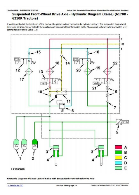
Suspended Front-Wheel Drive Axle - Theory of Operation
Cab Suspension - Theory of Operation
Suspended Front-Wheel Drive Axle - Schematics
Cab Suspension - Schematics
Suspended Front-Wheel Drive Axle - Tests and Adjustments
Cab Suspension - Tests and Adjustments
Machine-Specific Systems and Suspension Systems - Component Information
Suspended Front-Wheel Drive Axle - Component Information
Cab Suspension - Component Information
Machine-Specific Systems - Component Information
Operator's Cab
Operator's Cab - Operational Checks
Operator's Cab - Theory of Operation
Operator's Cab - Tests and Adjustments
Operator's Cab - Component Information
Air Conditioning System/ClimaTrak™ - Component Information
Special Tools
General Information
tm403819 - Tractors 6105R to 6210R Diagnostics -: (Worldwide Edition)
Table of Contents
Foreword
Information on Serial Numbers
Section 210: General Information
Group 05: Safety Measures
General Information - Safety - Summary of References
Recognize Safety Information
Understand Signal Words
Follow Safety Instructions
Prevent Machine Runaway
Operating the Tractor Safely
Operating the Loader Tractor Safely
Passenger Seat
Use Safety Lights and Devices
Towing Trailers/Implements Safely (Mass)
Use Caution On Slopes and Uneven Terrain
Freeing a Mired Machine
Avoid Backover Accidents
Handle Fluids Safely—Avoid Fires
Handling Batteries Safely
Prepare for Emergencies
Avoid High-Pressure Fluids
Service Cooling System Safely
Remove Paint Before Welding or Heating
Avoid Heating Near Pressurized Fluid Lines
Work In Ventilated Area
Avoid Contact with Agricultural Chemicals
Handle Agricultural Chemicals Safely
Stay Clear of Rotating Drivelines
Wear Protective Clothing
Protect Against Noise
Practice Safe Maintenance
Avoid Hot Exhaust
Exhaust Filter Cleaning
Clean Exhaust Filter Safely
Read Operator Manuals for ISOBUS Implements
Use Steps and Handholds Correctly
Use Seat Belt Properly
Park Machine Safely
Use Proper Lifting Equipment
Construct Dealer-Made Tools Safely
Support Machine Properly
Work in Clean Area
Illuminate Work Area Safely
Service Machines Safely
Service Accumulator Systems Safely
Service Tires Safely
Use Proper Tools
Service Front-Wheel Drive Tractor Safely
Avoid Eye Contact With Radar
Keep ROPS Installed Properly
Replace Safety Signs
Replace Safety Signs
Dispose of Waste Properly
Live With Safety
Safety Measures on Electronic Control Units
Servicing Electronic Control Units
Welding Near Electronic Control Units
Keep Electronic Control Unit Connectors Clean
Safety Instructions for Replacing a Halogen Bulb
Safety Instructions for Replacing Xenon (HID) Bulbs and Ballast Units
Group 10: General References
General Information - General References, Summary of References
Trademarks
Hydraulic Designators
Electrical Designators
General Information - Inch Bolt and Cap Screws, Torque Values
General Information - Metric Bolt and Cap Screws, Torque Values
General Information - Hydraulic System Inch Fittings, Torque Values
General Information - Hydraulic System Metric Fittings, Torque Values
General Information - Electrical System, Component Identification Table
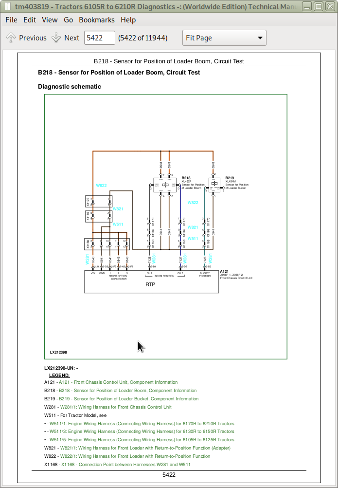
General Information - Electrical System, How to Read a Diagnostic Schematic
General Information - Electrical System, Lead Numbers and Color Codes
General Information - Electrical System, Symbols in Schematic, Wiring and Harness Diagrams
General Information - Electrical System, Check the Connectors
General Information - Electrical System, Approach to Tabular Diagnostic Procedures
General Information - Electrical System, Troubleshooting Unsolved Problems
General Information - Electrical System, Worksheet for Circuit/Harness Test
General Information - Electrical System, Visual Check
General - Electrical System, Faults and Circuit Tests
General - Electrical System, Test for Open Circuit under Load
General Information - Electrical System, Seven-Step Test Procedure
General Information - Hydraulic System, Symbols in Circuit Diagrams
General - Regions and Country Versions
Section 211: Diagnostic Trouble Codes
Group AIC: AIC Control Software
AIC 000158.03 - Supply Voltage (ELX) Too High
AIC 000158.04 - Supply Voltage (ELX) Too Low
AIC 000168.03 - Supply Voltage Too High
AIC 000168.04 - Supply Voltage Too Low
AIC 000628.02 - Control Software Internal Fault
AIC 000628.12 - Control Software Internal Fault
AIC 000629.12 - Control Software Internal Fault
AIC 003509.03 - Sensor Supply Voltage No. 1 Too High
AIC 003509.04 - Sensor Supply Voltage No. 1 Too Low
AIC 003509.06 - Sensor Supply Voltage No. 1, Current Too High
AIC 003510.03 - Sensor Supply Voltage No. 2 Too High
AIC 003510.04 - Sensor Supply Voltage No. 2 Too Low
AIC 003510.06 - Sensor Supply Voltage No. 2, Current Too High
AIC 176865.02 - Remote Control Switch for Rear PTO, Malfunction
AIC 520257.02 - Auto Mode Switch, Fault
AIC 520285.02 - Depth-Setting Potentiometer, Fault
AIC 520285.03 - Depth-Setting Potentiometer, Voltage Too High
AIC 520285.11 - Depth-Setting Potentiometer, Fault
AIC 520286.02 - Quick Raise/Lower Switch, Fault
AIC 520286.04 - Quick Raise/Lower Switch, Voltage Too Low
AIC 520286.11 - Quick Raise/Lower Switch, Fault
AIC 520870.02 - Configuration Data Fault, Internal Fault
AIC 520871.02 - Configuration Data Fault, Internal Fault
AIC 520872.02 - Configuration Data Fault, Internal Fault
AIC 522189.02 - iTEC™ Switch (CommandARM™), Error
AIC 522189.03 - iTEC™ Switch (CommandARM™), Voltage Too High
AIC 522189.04 - iTEC™ Switch (CommandARM™), Voltage Too Low
AIC 522189.11 - iTEC™ Switch (CommandARM™), Fault
AIC 522546.02 - Gear Selector Switch, Fault
AIC 522549.02 - Switch for Accelerator Pedal Position Memory, Error
AIC 523343.02 - Additional Switch at Multi-Function Lever, Error
AIC 523343.03 - Additional Switch at Multi-Function Lever, Voltage Too High
AIC 523343.04 - Additional Switch at Multi-Function Lever, Voltage Too Low
AIC 523349.02 - AutoTrac Resume Switch, Error
AIC 523349.03 - AutoTrac Resume Switch, Voltage Too High
AIC 523349.04 - AutoTrac Resume Switch, Voltage Too Low
AIC 523349.11 - AutoTrac Resume Switch, Malfunction
AIC 523670.02 - Speed Control Lever, Voltage Out of Valid Range
AIC 523670.02 - Shift Unit (DirectDrive Transmission), Fault
AIC 523670.11 - Speed Control Lever, Malfunction
AIC 523671.07 - Right-Hand Reverser, Fault
AIC 523671.11 - Shift Unit (DirectDrive Transmission), Fault
AIC 523671.13 - Right-Hand Reverser, Not Calibrated
AIC 523745.02 - Switch for iTEC Program Selection, Error
AIC 523745.03 - Switch for iTEC Program Selection, Voltage Too High
AIC 523745.04 - Switch for iTEC Program Selection, Voltage Too Low
AIC 523745.11 - Switch for iTEC™ Program Selection, Fault
AIC 523775.02 - Multi-Function Lever (E-ICV), Malfunction
AIC 523776.02 - Transport Lock Switch (E-ICV), Fault
AIC 523776.11 - Transport Lock Switch (E-ICV), Fault
AIC 523804.02 - Multi-Function Lever (E-ICV), Left-Right Axis, Signal Out of Permissible Range
AIC 523804.03 - Multi-Function (E-ICV) Lever, Left-Right Axis, Voltage Too High
AIC 523804.04 - Multi-Function (E-ICV) Lever, Left-Right Axis, Voltage Too Low
AIC 523805.02 - Multi-Function Lever (E-ICV), Fore-Aft Axis, Signal Out of Permissible Range
AIC 523805.03 - Multi-Function Lever (E-ICV), Fore-Aft Axis, Voltage Too High
AIC 523805.04 - Multi-Function Lever (E-ICV), Fore-Aft Axis, Voltage Too Low
AIC 523923.02 - Control Lever for E-SCV 1, Signal Out of Permissible Range
AIC 523923.03 - Control Lever for E-SCV 1, Voltage Too High
AIC 523923.04 - Control Lever for E-SCV 1, Voltage Too Low
AIC 523953.02 - Sensor Unit for Speed Control Lever, Signal Not in Specification
AIC 523953.03 - Sensor Unit for Speed Control Lever, Voltage Too High
AIC 523953.04 - Sensor Unit for Speed Control Lever, Voltage Too Low
AIC 523954.11 - Sensor Unit for Speed Control Lever (Speed Wheel), Output Signals do Not Match
AIC 523971.03 - Depth-Setting Potentiometer, Voltage Too High
AIC 523971.04 - Depth-Setting Potentiometer, Voltage Too Low
AIC 523971.13 - Depth-Setting Potentiometer, Not Calibrated
AIC 524017.31 - Reverse Drive Lever, Supply Voltage Faulty
AIC 524019.31 - LHR - Reverse Drive Lever, Faulty Signal from Neutral Switch
AIC 524020.31 - INFORMATION FOR OPERATOR: LHR Reverse Drive Lever Is in the Position for Forward or Reverse Travel During Start-Up Procedure
AIC 524021.31 - LHR - Reverse Drive Lever, Switches Are Actuated Simultaneously
AIC 524096.02 - Hand Throttle Potentiometer (AutoPowr/IVT Transmission), Voltage at Channel 1 and 2 Not in the Correct Ratio
AIC 524096.03 - Hand Throttle Potentiometer, Voltage Too High
AIC 524096.04 - Hand Throttle Potentiometer, Voltage Too Low
AIC 524103.02 - Control Lever for E-SCV 4, Defective
AIC 524103.03 - Control Lever for E-SCV 4, Voltage Too High
AIC 524103.04 - Control Lever for E-SCV 4, Voltage Too Low
AIC 524104.02 - Control Lever for E-SCV 3, Defective
AIC 524104.03 - Control Lever for E-SCV 3, Voltage Too High
AIC 524104.04 - Control Lever for E-SCV 3, Voltage Too Low
AIC 524105.02 - Control Lever for E-SCV 2, Defective
AIC 524105.03 - Control Lever for E-SCV 2, Voltage Too High
AIC 524105.04 - Control Lever for E-SCV 2, Voltage Too Low
AIC 524212.02 - Depth-Setting Potentiometer, Defective
AIC 524212.03 - Potentiometer for Hitch Control Lever, Voltage Too High
AIC 524212.04 - Potentiometer for Hitch Control Lever, Voltage Too Low
AIC 524212.11 - Quick Raise/Lower Switch, Fault
AIC 524216.02 - Front PTO Switch, Fault
AIC 524222.02 - APS Switch, Fault
AIC 524222.03 - APS Switch, Voltage Too High
AIC 524222.04 - APS Switch, Voltage Too Low
AIC 524222.11 - APS Switch, Fault
AIC 524224.02 - Rear PTO Switch, Fault
Group ATC: ATC Control Software
ATC 000158.03 - ATC Control Software, Supply Voltage Too High
ATC 000158.04 - ATC Control Software, Supply Voltage Too Low
ATC 000170.03 - Sensor for Inside Air Temperature, Voltage Too High
ATC 000170.04 - Sensor for Inside Air Temperature, Voltage Too Low
ATC 000628.12 - Control Software, Internal Fault
ATC 000630.02 - Control Software Internal Fault
ATC 000639.14 - Vehicle CAN Bus (500 kBd), Very High Error Rate
ATC 000871.03 - Refrigerant Pressure Sensor, Voltage Too High
ATC 000871.04 - Refrigerant Pressure Sensor, Voltage Too Low
ATC 000871.13 - Sensor for Refrigerant Pressure, Refrigerant Pressure Out of Range Low
ATC 000871.18 - Refrigerant Pressure Sensor, Malfunction
ATC 000876.03 - Compressor Clutch for Air-Conditioning, Voltage Too High
ATC 000876.04 - Compressor Clutch for Air-Conditioning, Voltage Too Low
ATC 000923.03 - Circulation Blower Motor Switched On, Voltage Too High
ATC 000923.04 - Circulation Blower Motor Switched On, Voltage Too Low
ATC 000923.12 - Circulation Blower Motor Switched On, Internal Fault
ATC 001546.03 - Heater Valve (Potentiometer), Voltage Too High
ATC 001546.04 - Heater Valve (Potentiometer), Voltage Too Low
ATC 001547.03 - Sensor for Evaporator Core Temperature, Voltage Too High
ATC 001547.04 - Sensor for Evaporator Core Temperature, Voltage Too Low
ATC 001548.03 - Outlet Air Temperature Sensor, Voltage Too High
ATC 001548.04 - Outlet Air Temperature Sensor, Voltage Too Low
ATC 001549.03 - Heater Valve (Actuator), Voltage Too High
ATC 001549.04 - Heater Valve (Actuator), Voltage Too Low
ATC 001549.07 - Heater Valve, Fault
ATC 001549.13 - Heater Valve, Not Calibrated
ATC 001551.03 - Pressurizer Fan Motor for Pressure Inside Cab, Voltage Too High
ATC 001551.04 - Pressurizer Fan Motor for Pressure Inside Cab, Voltage Too Low
ATC 002000.09 - Incorrect CAN BUS Message, Coolant Temperature from ECU Control Software
ATC 002071.09 - Incorrect CAN BUS Message, Information from CCU Control Software
ATC 002139.09 - Incorrect CAN BUS Message, Information from CSM Control Software
ATC 003509.03 - Sensor Supply Voltage, Voltage Too High
ATC 003509.04 - Sensor Supply Voltage, Voltage Too Low
ATC 003509.06 - Sensor Supply Voltage, Current Too High
ATC 520870.02 - Non-Volatile Memory (Area 1), Internal Fault
ATC 520871.02 - Non-Volatile Memory (Area 2), Internal Fault
ATC 520872.02 - Non-Volatile Memory (Area 3), Internal Fault
ATC 523848.03 - Actuator for Air Distribution (Potentiometer), Voltage Too High
ATC 523848.04 - Actuator for Air Distribution (Potentiometer), Voltage Too Low
ATC 523848.05 - Actuator for Air Distribution, Current Too Low
ATC 523848.06 - Actuator for Air Distribution, Current Too High
ATC 523848.07 - Actuator for Air Distribution, Fault
ATC 523848.13 - Actuator for Air Distribution, Not Calibrated
ATC 524202.03 - Sensor for Ambient Air Temperature (Rear), Voltage Too High
ATC 524202.04 - Sensor for Ambient Air Temperature (Rear), Voltage Too Low
ATC 524203.03 - Sensor for Ambient Air Temperature (Front), Voltage Too High
ATC 524203.04 - Sensor for Ambient Air Temperature (Front), Voltage Too Low
ATC 524219.02 - Defog Sensor, Frequency Out of Valid Range
ATC 524219.03 - Defog Sensor, Voltage Too High
ATC 524219.04 - Defog Sensor, Voltage Too Low
Group CCU: CCU Control Software
CCU 000084.04 - Wheel Speed Sensor, Voltage Too High
CCU 000084.05 - Wheel Speed Sensor, Open Circuit
CCU 000096.03 - Fuel Level Sensor Voltage Too High
CCU 000096.04 - Fuel Level Sensor Voltage Too Low
CCU 000096.17 - Fuel Level Too Low
CCU 000126.16 - Transmission Oil Filter Restricted
CCU 000158.03 - Control Software, Supply Voltage (ELX) Too High
CCU 000158.04 - Control Software, Supply Voltage (ELX) Too Low
CCU 000168.03 - Control Software, Supply Voltage (BAT) Too High
CCU 000168.04 - Control Software, Supply Voltage (BAT) Too Low
CCU 000177.00 - Transmission Oil Temperature Very High
CCU 000177.03 - Transmission Oil Temperature Sensor, Voltage Too High
CCU 000177.04 - Sensor for Transmission Oil Temperature, Voltage Too Low
CCU 000177.09 - CAN Bus Message Cannot Be Received, Information from PTA Control Software
CCU 000177.16 - Transmission Oil Temperature Is High
CCU 000177.19 - Transmission Oil Temperature Sensor, Fault
CCU 000177.31 - Transmission Oil Temperature Sensor, Fault
CCU 000190.09 - CAN BUS Message Cannot Be Received, Information from ECU Control Unit
CCU 000190.19 - Engine Speed Sensor Fault
CCU 000190.31 - Engine Speed Sensor Fault
CCU 000191.09 - CAN BUS Message Cannot Be Received, Information from PTA or PTQ Control Software
CCU 000191.19 - Transmission Output Speed Sensor, Malfunction
CCU 000191.31 - Transmission Output Speed Sensor, Malfunction
CCU 000237.02 - VIN Information, Mismatch
CCU 000237.14 - VIN Information, System Disabled
CCU 000237.31 - VIN Information, Incorrect
CCU 000247.09 - Incorrect CAN Bus Message, CAN Message from ECU Control Unit
CCU 000247.19 - Operating Hours Fault
CCU 000247.31 - Operating Hours Fault
CCU 000628.02 - Control Software, Internal Error
CCU 000629.12 - Control Software, Internal Error
CCU 000630.14 - Control Software, Internal Error
CCU 000639.12 - Vehicle CAN Bus (500 kBd), High Error Rate
CCU 000639.14 - Vehicle CAN Bus (500 kBd), Very High Error Rate
CCU 000746.31 - Differential Lock Solenoid Valve, Malfunction
CCU 001058.02 - Pressure Switch for Air Brake System, Malfunction
CCU 001058.03 - Pressure Switch for Air Brake System, Voltage Too High
CCU 001058.04 - Pressure Switch for Air Brake System, Voltage Too Low
CCU 001058.16 - INFORMATION FOR OPERATOR: Pressure Switch for Air-Brake System Is Not Activated (Pressure Too High)
CCU 001058.18 - INFORMATION FOR OPERATOR: Pressure Switch for Air-Brake System Is Not Activated (Pressure Too Low)
CCU 001058.31 - Pressure Switch for Air Brake System, Malfunction
CCU 001069.02 - INFORMATION FOR OPERATOR: Tire Circumference Not or Incorrectly Calibrated
CCU 001231.12 - Implement CAN Bus, High Error Rate
CCU 001231.14 - Implement CAN Bus, Very High Error Rate
CCU 001713.02 - Hydraulic Oil Filter Sensor, Fault
CCU 001713.15 - Hydraulic Oil Filter Dirty
CCU 001713.16 - Hydraulic Oil Filter Blocked
CCU 001865.09 - Incorrect CAN Bus Message, Information from OIC Control Software
CCU 001865.19 - Incorrect CAN Bus Message, Information from OIC Control Software
CCU 002000.09 - Incorrect CAN Bus Message, Information from ECU Control Unit
CCU 002003.09 - Incorrect CAN Bus Message, Information from PTA Control Software
CCU 002005.09 - Incorrect CAN Bus Message, Information from TIA Control Software
CCU 002019.09 - Incorrect CAN BUS Message, Information from XSC Control Software
CCU 002049.09 - Incorrect CAN Bus Message, Information from OIC Control Software
CCU 002139.09 - Incorrect CAN BUS Message, Information from CSM Control Software
CCU 002145.09 - Incorrect CAN Bus Message, Information from FCC Control Software
CCU 002221.09 - Incorrect CAN Bus Message, Information from PLC Control Software
CCU 003510.03 - 5-Volt Supply Voltage, Voltage Too High
CCU 003510.04 - 5-Volt Power Supply, Voltage Too Low
CCU 003510.06 - 5-Volt Supply Voltage, Current Too High
CCU 003597.02 - Wake-Up Signal, Voltage Too Low
CCU 003597.03 - 12-Volt Supply Voltage, Voltage Too High
CCU 003597.06 - 12 V Supply Voltage, Current Too High
CCU 520870.02 - Control Software, Internal Error
CCU 522578.09 - CAN Bus Message Cannot Be Received, Information from CSM Control Software
CCU 522578.19 - Switch for Selecting Front-Wheel Drive as Brake Assistance, Malfunction
CCU 522578.31 - Switch for Selecting Front-Wheel Drive as Brake Assistance, Malfunction
CCU 522580.09 - CAN Bus Message Cannot Be Received, Information from CSM Control Software
CCU 522580.19 - Switch for Automatic Mode of Front-Wheel Drive, Malfunction
CCU 522580.31 - Switch for Automatic Mode of Front-Wheel Drive, Malfunction
CCU 522581.09 - CAN Bus Message Cannot Be Received, Information from CSM Control Software
CCU 522581.19 - Switch for Switching On Front-Wheel Drive, Malfunction
CCU 522581.31 - Switch for Switching On Front-Wheel Drive, Malfunction
CCU 522763.09 - CAN BUS Message Cannot Be Received, Information from PTA or PTQ Control Software
CCU 522763.19 - Reverse Drive Lever, Malfunction
CCU 522763.31 - Reverse Drive Lever, Malfunction
CCU 523652.11 - Rear Chassis Control Unit Connected to Wrong Harness Connector
CCU 523666.03 - Control Software, Supply Voltage (BAT) Too High
CCU 523666.04 - Control Software, Supply Voltage (BAT) Too Low
CCU 523689.09 - Incorrect CAN BUS Message, CAN Message from OIC Control Software
CCU 523689.11 - Differential Lock Switch, Malfunction
CCU 523689.19 - Differential Lock Switch, Malfunction
CCU 523689.31 - Differential Lock Switch, Malfunction
CCU 523826.09 - Incorrect CAN BUS Message, CAN Message (Steering Angle Sensor) from XSC Control Software
CCU 524157.09 - Incorrect CAN Bus Message, CAN Message from OIC Control Software
CCU 524157.19 - Brake Pedal, Right Signal, Malfunction
CCU 524157.31 - Brake Pedal, Right Signal, Malfunction
CCU 524162.09 - Incorrect CAN Bus Message, CAN Message from OIC Control Software
CCU 524162.19 - Brake Pedal, Left Signal, Malfunction
CCU 524162.31 - Brake Pedal, Left Signal, Malfunction
CCU 524167.09 - Incorrect CAN BUS Message, CAN Message from TIA Control Software
CCU 524167.19 - Transmission Speeds, Malfunction
CCU 524167.31 - Transmission Speeds, Malfunction
CCU 524171.09 - Incorrect CAN BUS Message, CAN Message from TIA or PTQ Control Software
CCU 524171.19 - CAN BUS Message Regarding Commanded Direction of Travel, Malfunction
CCU 524171.31 - CAN BUS Message Regarding Commanded Direction of Travel, Malfunction
CCU 524191.02 - INFORMATION FOR OPERATOR: Air-Brake System, Fault
CCU 524191.03 - Air Brake System Solenoid Valve Voltage Too High
CCU 524191.05 - Air Brake System Solenoid Valve Voltage Too Low
CCU 524191.06 - Air Brake System Solenoid Valve Current Too High
CCU 524191.19 - INFORMATION FOR OPERATOR: Air-Brake System, Fault
CCU 524194.09 - Incorrect CAN BUS Message, CAN Message from PTQ Control Software
CCU 524194.19 - CAN BUS Message Regarding Direction of Travel, Malfunction
CCU 524194.31 - CAN BUS Message Regarding Direction of Travel, Malfunction
CCU 524218.09 - Incorrect CAN Bus Message, CAN Message from OIC Control Software
CCU 524218.19 - Park Lock Fault
CCU 524218.31 - Park Lock Fault
CCU 524235.04 - Front-Wheel Drive Solenoid Valve, Voltage Too High
CCU 524235.05 - Front-Wheel Drive Solenoid Valve, Voltage Too Low
CCU 524235.06 - Front-Wheel Drive Solenoid Valve, Current Too High
CCU 524235.31 - Front-Wheel Drive Solenoid Valve Fault
Group CLC: CLC Control Software
CLC 000444.06 - Control Software CLC, Current Too High
CLC 000628.02 - Control Software, Internal Error
CLC 000628.12 - Control Software Internal Error
CLC 000629.12 - Control Software Internal Error
CLC 000630.13 - Control Software, Internal Error
CLC 000920.03 - Acoustic Alarm Voltage Too High
CLC 000920.05 - Acoustic Alarm, Current Too Low
CLC 000920.06 - Acoustic Alarm Current Too High
CLC 001487.06 - Backlighting of Switch Console, Current Too High
CLC 001865.09 - Incorrect CAN Bus Message, Information from OIC Control Software
CLC 001877.06 - Implement Switch, Current Too High
CLC 001877.09 - Incorrect CAN Bus Message, Information from HCC Control Software
CLC 001877.19 - Hitch Control Fault
CLC 001877.31 - Hitch Control Fault
CLC 002000.09 - Incorrect CAN Bus Message, Information from ECU Control Unit
CLC 002025.09 - Incorrect CAN Bus Message, Information from ATC/ETC Control Software
CLC 002040.09 - Incorrect CAN Bus Message, Information from PDU Control Software
CLC 002049.09 - Incorrect CAN Bus Message, Information from OIC Control Software
CLC 002050.06 - Control Software, Current Too High
CLC 002055.09 - Incorrect CAN Bus Message, Information from RLC Control Software
CLC 002071.09 - Incorrect CAN BUS Message, Information from CCU Control Software
CLC 002145.09 - Incorrect CAN Bus Message, Information from FCC Control Software
CLC 002240.09 - Incorrect CAN Bus Message, Information from TEC Control Software
CLC 002360.03 - Worklights on Rear Fenders, Voltage Too High
CLC 002360.05 - Worklights on Rear Fenders, Current Too Low
CLC 002360.06 - Worklights on Rear Fenders, Current Too High
CLC 002368.03 - Left Extra-Wide Vehicle Warning Light (ECE), Voltage Too High
CLC 002368.05 - Left Extra-Wide Vehicle Warning Light (ECE), Current Too Low
CLC 002368.06 - Left Extra-Wide Vehicle Warning Light (ECE), Current Too High
CLC 002370.03 - Right Extra-Wide Vehicle Warning Light (ECE), Voltage Too High
CLC 002370.05 - Right Extra-Wide Vehicle Warning Light (ECE), Current Too Low
CLC 002370.06 - Right Extra-Wide Vehicle Warning Light (ECE), Current Too High
CLC 002372.03 - Brake Lights on Tractor, Voltage Too High
CLC 002372.05 - Brake Lights on Tractor, Current Too Low
CLC 002372.06 - Brake Lights on Tractor, Current Too High
CLC 002376.03 - Trailer Brake Light, Voltage Too High
CLC 002376.06 - Trailer Brake Light, Current Too High
CLC 002378.03 - Tail Lights and Extra-Wide Vehicle Warning Lights, Voltage Too High
CLC 002378.05 - Tail Lights and Extra-Wide Vehicle Warning Lights, Current Too Low
CLC 002378.06 - Tail Lights and Extra-Wide Vehicle Warning Lights, Current Too High
CLC 002392.03 - Back-Up Alarm, Voltage Too High
CLC 002392.06 - Back-Up Alarm, Current Too High
CLC 520490.03 - Power Supply for Attachment, Voltage Too High
CLC 520490.06 - Power Supply for Attachment, Current Too High
CLC 520491.03 - Power Supply for a Control Unit on Attachment, Voltage Too High
CLC 520491.06 - Power Supply for a Control Unit on Attachment, Current Too High
CLC 520715.03 - Fan Motor for Pressure Inside Cab, Voltage Too High
CLC 520715.05 - Fan Motor for Pressure Inside Cab, Current Too Low
CLC 520715.06 - Fan Motor for Pressure Inside Cab, Current Too High
CLC 520870.02 - Control Software, Internal Error
CLC 521835.20 - Control Software CLC, Ground Contact Malfunction
CLC 522434.03 - Windshield Wiper (Slow), Voltage Too High
CLC 522434.06 - Windshield Wiper (Slow), Current Too High
CLC 522435.03 - Windshield Wiper (Fast), Voltage Too High
CLC 522435.06 - Windshield Wiper (Fast), Current Too High
CLC 522620.03 - Horn, Voltage Too High
CLC 522620.05 - Horn, Current Too Low
CLC 522620.06 - Horn, Current Too High
CLC 522876.19 - CAN Bus Message, Fault
CLC 522876.31 - CAN Bus Message, Fault
CLC 524162.09 - CAN Bus Message Cannot be Received, Information from OIC Control Software
CLC 524259.00 - Cab Control Unit, Temperature Too High
CLC 524259.15 - Cab Control Unit, Temperature Too High
CLC 524259.16 - Cab Control Unit, Temperature Too High
Group CSC: CSC Control Software
CSC 000084.15 - Wheel Speed Detected During Calibration
CSC 000084.19 - CAN BUS Message, Wheel Speed Signal is Incorrect
CSC 000190.17 - Incorrect CAN Bus Message, Engine Speed Too Low
CSC 000190.19 - Incorrect CAN Bus Message, Engine Speed Not Detected
CSC 000574.19 - Incorrect CAN Bus Message, Enable Signal Not Detected or Incorrect
CSC 000628.12 - Control Software, Internal Error
CSC 000898.19 - Incorrect CAN Bus Message, Engine Speed Not Detected or Incorrect
CSC 002000.09 - Incorrect CAN Bus Message, Information from ECU Control Software
CSC 002003.09 - Incorrect CAN Bus Message, Information from TIA/TIQ Control Software
CSC 002005.09 - Incorrect CAN Bus Message, Information from TIQ Control Software
CSC 002006.09 - Incorrect CAN Bus Message, Information from EIC Control Software
CSC 002020.09 - Incorrect CAN Bus Message, Information from SFA Control Software
CSC 002049.09 - Incorrect CAN Bus Message, Information from OIC Control Software
CSC 002071.09 - Incorrect CAN Bus Message, Information from CCU Control Software
CSC 002145.09 - Incorrect CAN Bus Message, Information from FCC Control Software
CSC 003511.03 - 5-V Supply Voltage to CSC Sensors, Voltage Too High
CSC 003511.04 - 5-V Supply Voltage to CSC Sensors, Voltage Too Low
CSC 003511.06 - 5-V Supply Voltage to CSC Sensors, Current Too High
CSC 520870.02 - Control Software, Internal Error
CSC 520870.13 - Control Software Not or Incorrectly Calibrated
CSC 520871.02 - Control Software, Internal Error
CSC 520871.13 - Control Software, Internal Error
CSC 520892.02 - Control Software, Internal Error
CSC 522288.03 - Proportional Solenoid Valve for Cab Suspension, Voltage Too High
CSC 522288.05 - Proportional Solenoid Valve for Cab Suspension, Current Too Low
CSC 522288.06 - Proportional Solenoid Valve for Cab Suspension, Current Too High
CSC 522457.19 - Incorrect CAN Bus Message, Commanded Transmission Speed
CSC 522763.19 - Reverse Drive Lever, Fault
CSC 523666.03 - Supply Voltage of Rear Chassis Control Unit, Voltage Too High
CSC 523666.04 - Supply Voltage of Rear Chassis Control Unit, Voltage Too Low
CSC 523671.19 - Incorrect CAN BUS Message, Signal from Reverse Drive Lever
CSC 523948.03 - Solenoid Valve for Lowering Cab Suspension, Voltage Too High
CSC 523948.05 - Solenoid Valve for Lowering Cab Suspension, Current Too Low
CSC 523948.06 - Solenoid Valve for Lowering, Current Too High
CSC 523949.03 - Solenoid Valve for Raising, Voltage Too High
CSC 523949.05 - Solenoid Valve for Raising, Current Too Low
CSC 523949.06 - Solenoid Valve for Raising, Current Too High
CSC 523973.02 - Cab Position Out of Valid Range (2 - 3 V) During Calibration
CSC 523973.03 - Cab Suspension All the Way Up, Voltage Too High (During Calibration)
CSC 523973.04 - Cab Suspension All the Way Down, Voltage Too Low (During Calibration)
CSC 523973.07 - Cab Suspension Does Not Reach Level Position in Target Time, Malfunction
CSC 523973.10 - Cab Suspension Fails to Reach Level Position or End Stops in the Target Time During Calibration
CSC 523973.13 - Cab Suspension Sensor Not Calibrated Correctly
CSC 523973.14 - Cab Suspension Sensor Not Calibrated
CSC 523973.15 - Sensor for Cab Suspension at Bottom Stop, Incorrect Sensor Signal
CSC 523973.16 - Pressure Reduction, Lowest Position Not Reached, Malfunction
CSC 523973.17 - Cab Suspension All the Way Up During Calibration, Incorrect Sensor Signal
CSC 523973.18 - Bleeding (Cab Suspension), Level Position is Not Reached
CSC 523973.31 - Cab Moves in Wrong Direction During Calibration
CSC 524157.19 - Incorrect CAN BUS Message, Right Brake Pedal
CSC 524162.19 - Incorrect CAN BUS Message, Left Brake Pedal
CSC 524165.19 - Incorrect CAN Bus Message, Clutch
CSC 524167.19 - Incorrect CAN BUS Message, Transmission
Group CRU: CRU Control Software
CRU 000168.03 - Control Software, Supply Voltage (BAT) Too High
CRU 000168.04 - Control Software, Supply Voltage (BAT) Too Low
CRU 000237.02 - VIN Information, Mismatch
CRU 000639.12 - Vehicle CAN Bus (500 kBd), High Error Rate
CRU 002850.03 - Radio Antenna, Voltage Too High
CRU 002850.05 - Radio Antenna, Current Too Low
CRU 002850.06 - Radio Antenna, Current Too High
CRU 520194.02 - VIN Information, Mismatch
CRU 520772.12 - Control Software, Internal Fault
CRU 521156.12 - XM Satellite Radio, Fault
CRU 521780.06 - USB Connection, Current Too High
CRU 522453.12 - Control Software, Internal Fault
CRU 524259.00 - CD Drive, Temperature Too High
CRU 524259.31 - Radio, Temperature Too High
Group CSM: CSM Control Software
CSM 000168.04 - Control Software, Supply Voltage (BAT) Too Low
CSM 000628.02 - Control Software, Internal Error
CSM 000628.12 - Control Software, Internal Error
CSM 000629.12 - Control Software, Internal Error
CSM 000630.02 - Control Software, Internal Error
CSM 002076.09 - Incorrect CAN BUS Message, Information from RCU Control Software
CSM 520311.08 - Button for Radio and Audio Source Selection, Malfunction
CSM 520315.08 - Radio Mute Button, Malfunction
CSM 520502.08 - Selection Wheel, Malfunction
CSM 520742.08 - Button for Step Up, Malfunction
CSM 521842.08 - Button for Step Down, Malfunction
CSM 521843.08 - Button for Volume Control (Quieter), Malfunction
CSM 521844.08 - Confirm Button, Malfunction
CSM 521845.08 - Button J, Malfunction
CSM 521846.08 - Button I, Malfunction
CSM 521847.08 - Button H, Malfunction
CSM 521848.08 - Button G, Malfunction
CSM 521849.08 - Button F, Malfunction
CSM 521850.08 - Button E, Malfunction
CSM 521851.08 - Button D, Malfunction
CSM 521853.08 - Button C, Malfunction
CSM 521854.08 - Button B, Malfunction
CSM 521855.08 - Button A, Malfunction
CSM 521856.08 - Abort Button (X Button), Malfunction
CSM 521859.08 - Main Menu Button, Malfunction
CSM 522430.08 - Button for Volume Control (Louder), Malfunction
CSM 522559.08 - Transport Lock Button (E-ICVs), Malfunction
CSM 522560.08 - Button for Beacon Light, Malfunction
CSM 522562.08 - Button for Switching On the Additional Headlights, Malfunction
CSM 522563.08 - Button for Light Combination 2, Malfunction
CSM 522565.08 - Button for Light Combination 1, Malfunction
CSM 522566.08 - Hotkey for Engine Menu, Malfunction
CSM 522567.08 - Hotkey for iTEC Menu, Malfunction
CSM 522568.08 - Home Page Button, Malfunction
CSM 522569.08 - Hotkey for Rear PTO Menu, Malfunction
CSM 522570.08 - Hotkey for Raise Limit, Malfunction
CSM 522571.08 - Hotkey for SCV Menu, Malfunction
CSM 522572.08 - Hotkey for Rate-of Drop, Malfunction
CSM 522573.08 - Hazard Warning Light Button, Malfunction
CSM 522575.08 - Hotkey for Load/Depth Adjustment, Malfunction
CSM 522576.08 - Transport Lock Button (E-SCVs), Malfunction
CSM 522577.08 - Hotkey for Transmission Menu, Malfunction
CSM 522578.08 - Button for Selecting Front-Wheel Drive as Brake Assistance, Malfunction
CSM 522580.08 - On/Off Button for Automatic Mode of Front-Wheel Drive, Malfunction
CSM 522581.08 - Button for Switching On Front-Wheel Drive, Malfunction
CSM 523746.03 - Wakeup Signal, Voltage Too High
CSM 523746.04 - Wakeup Signal, Voltage Too Low
Group ECU: ECU Control Software
ECU 000027.03 - EGR Valve Position Signal Out of Range High
ECU 000027.04 - EGR Valve Position Signal Out of Range Low
ECU 000027.07 - EGR Valve Desired and Actual Position Mismatch
ECU 000051.03 - Air Throttle Actuator Position Signal Out of Range High
ECU 000051.04 - Air Throttle Actuator Position Signal Out of Range Low
ECU 000051.07 - Air Throttle Actuator Desired and Actual Position Mismatch
ECU 000051.14 - Air Throttle Actuator and EGR Valve Connectors Swapped
ECU 000084.31 - Wheel Speed Sensor, Fault
ECU 000094.03 - Low-Pressure Fuel Signal Out of Range High
ECU 000094.04 - Low-Pressure Fuel Signal Out of Range Low
ECU 000094.16 - Low-Pressure Fuel Signal Moderately High
ECU 000094.17 - Low-Pressure Fuel Signal Slightly Low
ECU 000094.18 - Low-Pressure Fuel Signal Moderately Low
ECU 000097.00 - Water-In-Fuel Level Extremely High
ECU 000097.03 - Water-In-Fuel Signal Voltage Out of Range High
ECU 000097.04 - Water-In-Fuel Signal Out Of Range Low
ECU 000097.16 - Water In Fuel Level Moderately High
ECU 000100.01 - Engine Oil Pressure Signal Extremely Low
ECU 000100.02 - Engine Oil Pressure is not Zero with Engine Stopped
ECU 000100.03 - Engine Oil Pressure Signal Out of Range High
ECU 000100.04 - Engine Oil Pressure Signal Out of Range Low
ECU 000100.06 - Engine Oil Pressure Signal, Resistance Too Low
ECU 000100.18 - Engine Oil Pressure Signal Moderately Low
ECU 000101.00 - Crankcase Pressure Signal Extremely High
ECU 000101.03 - Crankcase Pressure Signal Out of Range High
ECU 000101.04 - Crankcase Pressure Signal Out of Range Low
ECU 000101.06 - Crankcase Pressure Signal Out of Range High
ECU 000101.16 - Engine Crankcase Pressure Moderately High
ECU 000102.03 - Manifold Air Pressure Signal Out of Range High
ECU 000102.04 - Intake Manifold Air Pressure Signal Out of Range Low
ECU 000102.07 - Intake Manifold Air Pressure Signal In Range Invalid
ECU 000103.00 - VGT Speed Signal Extremely High
ECU 000103.02 - VGT Speed Signal Invalid
ECU 000103.05 - VGT Speed Circuit Has High Resistance
ECU 000105.00 - Manifold Temperature Signal Extremely High
ECU 000105.03 - Manifold Temperature Signal Out of Range High
ECU 000105.04 - Manifold Temperature Signal Out of Range Low
ECU 000105.15 - Intake Manifold Temperature Signal Slightly High
ECU 000105.16 - Intake Manifold Air Temperature Signal Moderately High
ECU 000107.00 - Air Filter Pressure Differential Extremely High
ECU 000107.15 - Air Filter Pressure Differential Slightly High
ECU 000107.16 - Air Filter Pressure Differential Moderately High
ECU 000107.31 - Air Filter Pressure Differential Fault
ECU 000108.02 - Barometric Pressure Signal Invalid
ECU 000108.07 - Barometric Pressure Signal Mismatch
ECU 000109.01 - Engine Coolant Signal Extremely Low
ECU 000109.03 - Engine Coolant Signal Out of Range High
ECU 000109.04 - Engine Coolant Signal Out of Range Low
ECU 000109.17 - Engine Coolant Pressure Signal Slightly Low
ECU 000109.18 - Engine Coolant Pressure Signal Moderately Low
ECU 000109.31 - Engine Coolant Pressure Signal Fault
ECU 000110.00 - Engine Coolant Temperature Signal Extremely High
ECU 000110.03 - Engine Coolant Temperature Signal Out of Range High
ECU 000110.04 - Coolant Temperature Signal Out of Range Low
ECU 000110.15 - Engine Coolant Temperature Signal Slightly High
ECU 000110.16 - Engine Coolant Temperature Signal Moderately High
ECU 000110.17 - Engine Coolant Temperature Signal Slightly Low
ECU 000111.01 - Engine Coolant Level Alarm Switch Activated at High Coolant Temperature
ECU 000111.07 - Engine Coolant Level Switch Mismatch
ECU 000111.17 - Engine Coolant Level Information Switch Activated
ECU 000111.18 - Engine Coolant Level Alarm Switch Activated at Moderate Coolant Temperature
ECU 000157.01 - Fuel Rail Pressure Signal Extremely Low
ECU 000157.03 - Fuel Rail Pressure Signal Out of Range High
ECU 000157.04 - Fuel Rail Pressure Signal Out of Range Low
ECU 000157.16 - Fuel Rail Pressure Signal Moderately High
ECU 000157.17 - Fuel Rail Pressure Signal Slightly Low
ECU 000157.18 - Fuel Rail Pressure Signal Moderately Low
ECU 000158.12 - ECU Power Down Error
ECU 000158.31 - Key Switch Fault
ECU 000160.02 - Wheel Speed Sensor Signal Invalid
ECU 000168.01 - Unswitched Battery Voltage Extremely Low
ECU 000168.16 - Unswitched Battery Voltage Moderately High
ECU 000168.17 - Unswitched Battery Power Too Low (Engine Speed above 1500 rpm)
ECU 000168.18 - Unswitched Battery Voltage Moderately Low
ECU 000174.00 - Fuel Temperature Signal Extremely High
ECU 000174.03 - Fuel Temperature Signal Out of Range High
ECU 000174.04 - Fuel Temperature Signal Out of Range Low
ECU 000174.16 - Fuel Temperature Signal Moderately High
ECU 000189.31 - Engine Speed Derate Condition Exists
ECU 000190.00 - Engine Speed Extremely High
ECU 000190.16 - Engine Speed Moderately High
ECU 000237.02 - VIN Information, Mismatch
ECU 000237.13 - VIN Information, Option Code Invalid
ECU 000237.31 - VIN Information, Incorrect
ECU 000412.00 - EGR Temperature Signal Extremely High
ECU 000412.03 - EGR Temperature Signal Out of Range High
ECU 000412.04 - EGR Temperature Signal Out of Range Low
ECU 000412.15 - EGR Temperature Signal Slightly High
ECU 000412.16 - EGR Temperature Signal Moderately High
ECU 000611.03 - Injector Drive #1 Shorted to Voltage Source
ECU 000611.04 - Injector Drive #1 Shorted to Ground
ECU 000612.03 - Injector Drive #2 Shorted to Voltage Source
ECU 000612.04 - Injector Drive #2 Shorted to Ground
ECU 000629.11 - ECU Binary Input Error
ECU 000629.12 - ECU EEPROM Error
ECU 000629.13 - ECU Boot Block Error
ECU 000636.02 - Camshaft Speed Signal Invalid
ECU 000636.05 - Camshaft Position Sensor Circuit Has High Resistance
ECU 000636.06 - Camshaft Position Sensor Circuit Has Low Resistance
ECU 000636.08 - Camshaft Speed Signal Missing
ECU 000636.10 - Camshaft Speed Signal Rate of Change Abnormal
ECU 000637.02 - Crankshaft Speed Signal Invalid
ECU 000637.05 - High Resistance in Crankshaft Speed Circuit
ECU 000637.06 - Low Resistance in Crankshaft Speed Circuit
ECU 000637.07 - Camshaft Speed and Crankshaft Speed Signals Out of Sync
ECU 000637.08 - Crankshaft Speed Signal Missing
ECU 000637.10 - Crankshaft Position Signal Rate of Change Abnormal
ECU 000641.00 - VGT Actuator Temperature Extremely High
ECU 000641.05 - VGT Actuator Drive Circuit Has High Resistance
ECU 000641.06 - VGT Actuator Drive Circuit Has Low Resistance
ECU 000641.07 - VGT Actuator Learn Error
ECU 000641.09 - VGT Actuator Loss of Communication
ECU 000641.12 - VGT Actuator Internal Error
ECU 000641.13 - VGT Actuator Calibration Error
ECU 000641.16 - VGT Actuator Temperature Slightly High
ECU 000641.31 - VGT Actuator Supply Voltage Fault
ECU 000647.05 - Proportional Solenoid Valve for Charge Air Cooler Hydraulic Motor, Current Too Low
ECU 000647.06 - Proportional Solenoid Valve for Charge Air Cooler Hydraulic Motor, Current Too High
ECU 000651.02 - Injector #1 Part Number Data Invalid
ECU 000651.05 - Injector #1 Circuit Has High Resistance
ECU 000651.06 - Injector #1 Circuit Has Low Resistance
ECU 000651.13 - Injector #1 Calibration Fault
ECU 000651.18 - Injector #1 Not Responding
ECU 000652.02 - Injector #2 Part Number Data Invalid
ECU 000652.05 - Injector #2 Circuit Has High Resistance
ECU 000652.06 - Injector #2 Circuit Has Low Resistance
ECU 000652.13 - Injector #2 Calibration Fault
ECU 000652.18 - Injector #2 Not Responding
ECU 000653.02 - Injector #3 Part Number Data Invalid
ECU 000653.05 - Injector #3 Circuit Has High Resistance
ECU 000653.06 - Injector #3 Circuit Has Low Resistance
ECU 000653.13 - Injector #3 Calibration Fault
ECU 000653.18 - Injector #3 Not Responding
ECU 000654.02 - Injector #4 Part Number Data Invalid
ECU 000654.05 - Injector #4 Circuit Has High Resistance
ECU 000654.06 - Injector #4 Circuit Has Low Resistance
ECU 000654.13 - Injector #4 Calibration Fault
ECU 000654.18 - Injector #4 Not Responding
ECU 000655.02 - Injector #5 Part Number Data Invalid
ECU 000655.05 - Injector #5 Circuit Has High Resistance
ECU 000655.06 - Injector #5 Circuit Has Low Resistance
ECU 000655.13 - Injector #5 Calibration Fault
ECU 000655.18 - Injector #5 Not Responding
ECU 000656.02 - Injector #6 Part Number Data Invalid
ECU 000656.05 - Injector #6 Circuit Has High Resistance
ECU 000656.06 - Injector #6 Circuit Has Low Resistance
ECU 000656.13 - Injector #6 Calibration Fault
ECU 000656.18 - Injector #6 Not Responding
ECU 000676.03 - Relay for Electric Starting Aid, Current Too High
ECU 000676.05 - Relay for Electric Starting Aid, Current Too Low
ECU 000676.06 - Cold Start Aid Drive Circuit Has Low Resistance
ECU 000676.14 - Cold Start Aid Signal Received When Not Expected
ECU 000676.31 - Cold Start Aid Relay Signal Not Received When Expected
ECU 000876.05 - Air Conditioner Compressor Clutch, Current Too Low
ECU 000876.06 - Air Conditioner Compressor Clutch, Current Too High
ECU 000970.31 - Immobilizer, Fault
ECU 000971.31 - External Derate Commanded
ECU 001069.31 - Tire Size Error
ECU 001075.02 - Low-Pressure Fuel Pump Data Erratic
ECU 001075.04 - Low-Pressure Fuel Pump Input Voltage Low
ECU 001075.06 - Low-Pressure Fuel Pump Circuit Has Low Resistance
ECU 001075.09 - Low-Pressure Fuel Pump Loss of Communication
ECU 001075.15 - Low-Pressure Fuel Pump Temperature Slightly High
ECU 001136.00 - ECU Temperature Signal Extremely High
ECU 001136.02 - ECU Temperature Signal Invalid
ECU 001136.16 - ECU Temperature Signal Moderately High
ECU 001172.12 - Intake Air Temperature Fault
ECU 001176.07 - Intake Air Pressure Mismatch
ECU 001176.12 - Intake Air Pressure Fault
ECU 001180.00 - Calculated VGT Turbine Inlet Temperature Extremely High
ECU 001180.16 - Calculated VGT Turbine Inlet Temperature Moderately High
ECU 001209.03 - Exhaust Manifold Pressure Signal Out of Range High
ECU 001209.04 - Exhaust Manifold Pressure Signal Out of Range Low
ECU 001209.07 - Exhaust Manifold Pressure Mismatch
ECU 001321.05 - Engine Starter Solenoid Lockout Relay Circuit Has High Resistance
ECU 001321.06 - Engine Starter Solenoid Lockout Relay Circuit Has Low Resistance
ECU 001321.16 - Engine Starter Engaged for Too Long
ECU 001321.31 - Engine Speed Zero with Starter Solenoid Energized
ECU 001322.31 - Engine Misfires Detected
ECU 001347.01 - Suction Control Valve Sticking and Fuel Rail Pressure Extremely Low
ECU 001347.05 - Suction Control Valve Circuit Has High Resistance
ECU 001347.06 - Suction Control Valve Circuit Has Low Resistance
ECU 001347.16 - Suction Control Valve Sticking and Fuel Rail Pressure Moderately High
ECU 001347.18 - Suction Control Valve Sticking and Fuel Rail Pressure Slightly Low
ECU 001351.05 - Compressor Clutch for Trailer Air Brakes, Current Too Low
ECU 001351.06 - Compressor Clutch for Trailer Air Brakes, Current Too High
ECU 001550.05 - A/C Compressor Clutch, Current Too Low
ECU 001550.06 - A/C Compressor Clutch, Current Too High
ECU 001569.31 - Engine in Derate Condition
ECU 002003.09 - Incorrect CAN Bus Message, Information from PTQ/PTA Control Software
ECU 002006.09 - Incorrect CAN Bus Message, Information from EIC Control Software
ECU 002006.14 - Control Software Internal Fault
ECU 002006.19 - Control Software, Internal Fault
ECU 002025.09 - Incorrect CAN Bus Message, Information from ATC/ETC Control Software
ECU 002071.09 - Incorrect CAN Bus Message, Information from CCU Control Software
ECU 002629.03 - Fixed Turbocharger Compressor Outlet Temperature Signal Out of Range High
ECU 002629.04 - Fixed Turbocharger Compressor Outlet Temperature Signal Out of Range Low
ECU 002630.00 - Charge Air Cooler Outlet Temperature Signal Extremely High
ECU 002630.03 - Charge Air Cooler Outlet Temperature Signal Out Of Range High
ECU 002630.04 - Charge Air Cooler Outlet Temperature Signal Out of Range Low
ECU 002630.15 - Charge Air Cooler Outlet Temperature Signal Slightly High
ECU 002630.16 - Charge Air Cooler Outlet Temperature Signal Moderately High
ECU 002659.02 - EGR Flow Signal Invalid
ECU 002659.03 - EGR Flow Signal Out of Range High
ECU 002659.04 - EGR Flow Signal Out of Range Low
ECU 002659.14 - EGR Flow Signal Fault
ECU 002659.15 - EGR Flow Signal Moderately High
ECU 002659.17 - EGR Flow Signal Moderately Low
ECU 002790.16 - Calculated VGT Compressor Outlet Temperature Moderately High
ECU 002791.05 - EGR Valve Drive Circuit Fault
ECU 002791.06 - EGR Valve Drive Circuit Has Low Resistance
ECU 002791.07 - EGR Valve Desired and Actual Position Mismatch During a Learn
ECU 002791.13 - EGR Valve Calibration Error
ECU 002795.07 - VGT Vane Desired and Actual Position Mismatch
ECU 002795.31 - Invalid Position of Variable Geometry Turbocharger
ECU 002797.03 - Injector High Voltage Supply #1 Out of Range High
ECU 002797.05 - Injector High Voltage Supply #1 Circuit Has High Resistance
ECU 002797.06 - Injector High Voltage Supply #1 Circuit Has Low Resistance
ECU 002798.03 - Injector High Voltage Supply #2 Out of Range High
ECU 002798.05 - Injector High Voltage Supply #2 Circuit Has High Resistance
ECU 002798.06 - Injector High Voltage Supply #2 Circuit Has Low Resistance
ECU 003246.00 - DPF Outlet Temperature Extremely High
ECU 003246.12 - DPF Outlet Temperature Fault
ECU 003251.00 - DPF Differential Pressure Signal Not Responding
ECU 003251.02 - DPF Differential Pressure Signal Invalid
ECU 003251.03 - DPF Differential Pressure Signal Out of Range High
ECU 003251.04 - DPF Differential Pressure Signal Out of Range Low
ECU 003251.04 - DPF Differential Pressure Sensor Fault
ECU 003353.31 - Alternator, Fault
ECU 003464.05 - Air Throttle Actuator Drive Circuit Fault
ECU 003464.06 - Air Throttle Actuator Drive Circuit Has Low Resistance
ECU 003464.07 - Discrepancy between Actual and Set Positions of the Throttle Actuator during Recording
ECU 003464.13 - Air Throttle Actuator Calibration Error
ECU 003465.00 - Exhaust Throttle Actuator Temperature Extremely High
ECU 003465.05 - Exhaust Throttle Actuator Drive Circuit Has High Resistance
ECU 003465.06 - Exhaust Throttle Actuator Drive Circuit Has Low Resistance
ECU 003465.07 - Exhaust Throttle Actuator Learn Error
ECU 003465.09 - Exhaust Throttle Actuator Loss of Communication
ECU 003465.12 - Exhaust Throttle Actuator Internal Error
ECU 003465.13 - Exhaust Throttle Actuator Calibration Error
ECU 003465.16 - Exhaust Throttle Actuator Temperature Moderately High
ECU 003465.31 - Exhaust Throttle Actuator Supply Voltage Fault
ECU 003471.03 - Fuel Dosing Control Valve Signal Out of Range High
ECU 003471.04 - Fuel Dosing Control Valve Signal Out of Range Low
ECU 003471.05 - Fuel Dosing Control Valve Circuit Has High Resistance
ECU 003471.11 - Fuel Dosing Control Valve Circuit Fault
ECU 003480.01 - Fuel Dosing Inlet Pressure Signal Extremely Low
ECU 003480.03 - Fuel Dosing Inlet Pressure Signal Out of Range High
ECU 003480.04 - Fuel Dosing Inlet Pressure Signal Out of Range Low
ECU 003480.07 - Fuel Dosing Inlet Sensor Desired and Actual Pressure Mismatch
ECU 003480.18 - Fuel Dosing Inlet Pressure Signal Moderately Low
ECU 003482.03 - Fuel Dosing Shutoff Valve Signal Out of Range High
ECU 003482.04 - Fuel Dosing Shutoff Valve Signal Out of Range Low
ECU 003482.05 - Fuel Dosing Shutoff Valve Circuit Has High Resistance
ECU 003482.16 - Fuel Dosing Shut-Off Valve Stuck Open
ECU 003509.03 - Sensor Supply #1 Voltage Out of Range High
ECU 003509.04 - Sensor Supply Voltage 1 Out of Range Low
ECU 003510.03 - Sensor Supply Voltage 2 Out of Range High
ECU 003510.04 - Sensor Supply Voltage 2 Out of Range Low
ECU 003511.03 - Sensor Supply Voltage 3 Out of Range High
ECU 003511.04 - Sensor Supply Voltage 3 Out of Range Low
ECU 003512.03 - Sensor Supply #4 Voltage Out of Range High
ECU 003512.04 - Sensor Supply #4 Voltage Out of Range Low
ECU 003513.03 - Sensor Supply #5 Voltage Out of Range High
ECU 003513.04 - Sensor Supply #5 Voltage Out of Range Low
ECU 003514.03 - Sensor Supply Voltage 6 Out of Range High
ECU 003514.04 - Sensor Supply Voltage 6 Out of Range Low
ECU 003556.16 - Fuel Dosing Injector Stuck Closed
ECU 003556.18 - Fuel Dosing Injector Stuck Open
ECU 003597.01 - Injector High Voltage Supply Extremely Low
ECU 003673.31 - Exhaust Throttle Actuator Desired and Actual Position Mismatch
ECU 003711.14 - Regeneration Not Possible, Exhaust Temperature Fault
ECU 003711.31 - Regeneration Not Possible, Exhaust Temperature Too Low
ECU 003719.00 - Calculated Soot Level Extremely High
ECU 003719.10 - Calculated Soot Load Rate of Change Abnormal
ECU 003719.13 - Excessive DPF Recovery Attempts
ECU 003719.14 - Calculated Soot Level Extremely High
ECU 003719.15 - Calculated Soot Level Slightly High
ECU 003719.16 - Calculated Soot Level Moderately High
ECU 003720.15 - Calculated Ash Level Slightly High
ECU 003720.16 - Calculated Ash Level Moderately High
ECU 003936.00 - Calculated Unintended Combustibles in DPF Extremely High
ECU 003936.15 - Calculated Unintended Combustibles in DPF Slightly High
ECU 003936.16 - Calculated Unintended Combustibles in DPF Moderately High
ECU 004077.03 - Fuel Dosing Outlet Pressure Signal Out of Range High
ECU 004077.04 - Fuel Dosing Outlet Pressure Signal Out of Range Low
ECU 004077.07 - Fuel Dosing Outlet Pressure Signal Invalid
ECU 004490.12 - Intake Air Humidity Fault
ECU 004765.00 - DOC Inlet Temperature Extremely High
ECU 004765.12 - DOC Inlet Temperature Fault
ECU 004766.12 - DOC Outlet Temperature Fault
ECU 004766.16 - DOC Outlet Temperature Moderately High
ECU 004766.17 - DOC Outlet Temperature Slightly Low
ECU 004766.18 - DOC Outlet Temperature Moderately Low
ECU 004795.13 - Exhaust Filter Calibration Fault
ECU 004795.31 - DPF Missing
ECU 005018.00 - Calculated Unintended Combustibles in DOC Extremely High
ECU 005018.15 - Calculated Unintended Combustibles in DOC Slightly High
ECU 005018.16 - Calculated Unintended Combustibles in DOC Moderately High
ECU 005125.03 - Sensor Supply Voltage 7 Out of Range High
ECU 005125.04 - Sensor Supply Voltage 7 Out of Range Low
ECU 005126.03 - Sensor Supply Voltage 8 Out of Range High
ECU 005126.04 - Sensor Supply Voltage 8 Out of Range Low
ECU 005127.03 - Sensor Supply Voltage 9 Out of Range High
ECU 005127.04 - Sensor Supply Voltage 9 Out of Range Low
ECU 005298.01 - DOC Efficiency Extremely Low
ECU 005298.18 - DOC Efficiency Moderately Low
ECU 005456.00 - Fuel Dosing Inlet Temperature Signal Extremely High
ECU 005456.01 - Fuel Dosing Inlet Temperature Signal Extremely Low
ECU 005456.03 - Fuel Dosing Inlet Temperature Signal Out of Range High
ECU 005456.04 - Fuel Dosing Inlet Temperature Signal Out of Range Low
ECU 055010.31 - Illegal ECU Structure
ECU 520956.05 - Relay for Battery Cut-Off Relay, Current Too Low
ECU 520956.06 - Relay for Battery Cut-Off Relay, Current Too High
ECU 521192.11 - Engine Shutdown, Time-Out
ECU 521214.09 - Incorrect CAN Bus Message, Information from EIC Control Software
ECU 521214.14 - VIN Information, Mismatch
ECU 522458.02 - Fuel Dosing Pump Data Erratic
ECU 522458.03 - Fuel Dosing Pump Supply Voltage High
ECU 522458.04 - Fuel Dosing Pump Supply Voltage Low
ECU 522458.06 - Fuel Dosing Pump Circuit Has Low Resistance
ECU 522458.09 - Fuel Dosing Pump Loss of Communication
ECU 522458.15 - Fuel Dosing Pump Temperature Slightly High
ECU 522494.09 - Intake Air Sensor Communication Error
ECU 522495.09 - Engine Exhaust Filter Temperature Module Loss of Communication
ECU 523744.09 - Incorrect CAN BUS Message, Status of Air Conditioner Compressor Clutch
Group EIC: EIC Control Software
EIC 000628.02 - Control Software Internal Fault
EIC 001237.31 - Immobilizer Key Identification Fault
EIC 002000.09 - Incorrect CAN BUS Message, Information from ECU Control Software
EIC 002007.09 - Incorrect CAN BUS Message, Information from RPT Control Software
EIC 002029.09 - Incorrect CAN BUS Message, Information from Immobilizer Control Unit
EIC 002029.12 - Incorrect Information from Immobilizer Control Unit
EIC 002140.09 - Incorrect CAN BUS Message, Information from AIC Control Software
EIC 003695.14 - Automatic Exhaust Filter Cleaning Deactivated
EIC 003719.15 - Automatic Exhaust Filter Cleaning Not Completed
EIC 521192.12 - VIN Information Mismatch
EIC 521192.13 - VIN Information Mismatch
EIC 521214.11 - Immobilizer Malfunction
EIC 521214.31 - Memory Information Invalid
EIC 521321.09 - Incorrect CAN BUS Message, Information from Immobilizer
EIC 521321.12 - Immobilizer Key Unknown
EIC 521322.07 - Immobilizer Antenna Fault
EIC 521322.31 - Immobilizer Key Chip Fault
EIC 523702.14 - VIN Information Mismatch
EIC 523702.31 - Memory Information Invalid
Group ETC: ETC Control Software
ETC 000158.03 - ETC Control Software, Supply Voltage Too High
ETC 000158.04 - ETC Control Software, Supply Voltage Too Low
ETC 000170.03 - Sensor for Inside Air Temperature, Voltage Too High
ETC 000170.04 - Sensor for Inside Air Temperature, Voltage Too Low
ETC 000628.12 - Control Software Internal Fault
ETC 000630.02 - Control Software Internal Fault
ETC 000639.14 - Vehicle CAN BUS, Very High Error Rate
ETC 000871.03 - Refrigerant Pressure Sensor, Voltage Too High
ETC 000871.04 - Refrigerant Pressure Sensor, Voltage Too Low
ETC 000871.13 - Sensor for Refrigerant Pressure, Refrigerant Pressure Out of Range Low
ETC 000871.18 - Refrigerant Pressure Sensor, Malfunction
ETC 000876.03 - Compressor Clutch Switched On, Voltage Too High
ETC 000876.04 - Compressor Clutch Switched On, Voltage Too Low
ETC 000876.10 - Compressor Clutch, Malfunction
ETC 000876.14 - Compressor Clutch, Overload Protection
ETC 000923.03 - Circulation Fan Motor On, Voltage Too High
ETC 000923.04 - Circulation Fan Motor On, Voltage Too Low
ETC 000923.12 - Fan Motor Switched On, Internal Fault
ETC 001546.03 - Heater Valve (Potentiometer), Voltage Too High
ETC 001546.04 - Heater Valve (Potentiometer), Voltage Too Low
ETC 001547.03 - Sensor for Evaporator Core Temperature, Voltage Too High
ETC 001547.04 - Sensor for Evaporator Core Temperature, Voltage Too Low
ETC 001548.03 - Outlet Air Temperature Sensor, Voltage Too High
ETC 001548.04 - Outlet Air Temperature Sensor, Voltage Too Low
ETC 001549.03 - Heater Valve (Actuator), Voltage Too High
ETC 001549.04 - Heater Valve (Actuator), Voltage Too Low
ETC 001549.07 - Heater Valve, Malfunction
ETC 001549.13 - Heater Valve, Not Calibrated
ETC 001551.03 - Pressurizer Fan Motor for Pressure inside Cab, Voltage Too High
ETC 001551.04 - Pressurizer Fan Motor for Pressure inside Cab, Voltage Too Low
ETC 002000.09 - Incorrect CAN BUS Message, Coolant Temperature from ECU
ETC 002139.09 - Incorrect CAN BUS Message, Information from CSM Control Software
ETC 003509.03 - 5-Volt Supply Voltage, Voltage Too High
ETC 003509.04 - 5-Volt Supply Voltage, Voltage Too Low
ETC 520870.02 - Control Software Internal Fault
ETC 520871.02 - Control Software Internal Fault
ETC 520872.02 - Control Software Internal Fault
ETC 523848.03 - Actuator for Air Distribution (Potentiometer), Voltage Too High
ETC 523848.04 - Actuator for Air Distribution (Potentiometer), Voltage Too Low
ETC 523848.05 - Actuator for Air Distribution, Current Too Low
ETC 523848.06 - Actuator for Air Distribution, Current Too High
ETC 523848.07 - Actuator for Air Distribution, Malfunction
ETC 523848.13 - Actuator for Air Distribution, Not Calibrated
ETC 524202.03 - Sensor for Ambient Air Temperature (Rear), Voltage Too High
ETC 524202.04 - Sensor for Ambient Air Temperature (Rear), Voltage Too Low
ETC 524203.03 - Sensor for Ambient Air Temperature (Front), Voltage Too High
ETC 524203.04 - Sensor for Ambient Air Temperature (Front), Voltage Too Low
ETC 524219.02 - Defog Sensor, Frequency Out of Valid Range
ETC 524219.03 - Defog Sensor, Voltage Too High
ETC 524219.04 - Defog Sensor, Voltage Too Low
Group FCC: FCC Control Software
FCC 000158.00 - Instrument Unit, Supply Voltage (ELX) Too High
FCC 000158.01 - Instrument Unit, Supply Voltage (ELX) Too Low
FCC 000158.17 - Instrument Unit, Supply Voltage (ELX) Too Low
FCC 000158.18 - Instrument Unit, Supply Voltage (ELX) Too Low
FCC 000168.18 - Instrument Unit, Supply Voltage (BAT) Too Low
FCC 000237.02 - VIN Information, Mismatch
FCC 000237.14 - VIN Information, System Disabled
FCC 000237.31 - VIN Information, Incorrect
FCC 000628.02 - Control Software, Internal Error
FCC 000628.12 - Control Software Internal Fault
FCC 000629.12 - Control Software, Internal Error
FCC 000630.02 - Control Software, Internal Error
FCC 000639.12 - Vehicle CAN Bus (500 kBd), High Error Rate
FCC 000639.14 - Vehicle CAN BUS (500 kBd), Very High Error Rate
FCC 002003.09 - Incorrect CAN Bus Message, Information from PTA Control Software
FCC 002005.09 - Incorrect CAN BUS Message, Information from TIA Control Software
FCC 002825.13 - Incorrect CAN BUS Message, Information from PTA or PTQ Control Software
FCC 002825.31 - Reverse Drive Lever, Fault
FCC 002826.31 - Reverse Drive Lever, Fault
FCC 002828.31 - Reverse drive lever, power-zero switch, move switch and either the forward or reverse switch are activated simultaneously for too long a period.
FCC 002829.31 - Reverse drive lever, park lock switch, and neutral switch or power zero switch are activated simultaneously for too long a period
FCC 002863.02 - Switch for Windshield and Rear Window Wipers, Fault at Windshield
FCC 002865.02 - Switch for windshield and rear window wipers, Malfunction at rear window
FCC 002872.02 - Light Switch, Fault
FCC 002876.02 - Turn-Signal Lever, Fault
FCC 522122.31 - Incorrect CAN BUS Message, Information from PTA or PTQ Control Software
FCC 522123.31 - Incorrect CAN BUS Message, Information from PTA or PTQ Control Software
FCC 522124.31 - Incorrect CAN BUS Message, Information from PTA or PTQ Control Software
FCC 522125.31 - Incorrect CAN BUS Message, Information from PTA or PTQ Control Software
FCC 522358.31 - Incorrect CAN BUS Message, Information from PTA or PTQ Control Software
FCC 524020.31 - INFORMATION FOR OPERATOR: Reverse Drive Lever Not in Neutral Position During Start-Up
FCC 524022.31 - Reverse Drive Lever, Fault
FCC 524264.02 - Incorrect CAN BUS Message, Information from PTA or PTQ Control Software
Group GPM: GPM Control Software
GPM 000168.04 - Supply Voltage (BAT) Too Low
GPM 000191.00 - INFORMATION FOR OPERATOR: Reduce Travel Speed Using Brakes
GPM 000628.02 - Control Software Internal Fault
GPM 000630.02 - Control Software Internal Fault
GPM 521926.12 - INFORMATION FOR OPERATOR: Range C Jumped Out
GPM 521927.12 - INFORMATION FOR OPERATOR: Range B Jumped Out
GPM 521928.05 - Gear 8 Solenoid Current Too Low
GPM 521928.06 - Gear 8 Solenoid Current Too High
GPM 521928.07 - Gear 8 Fault
GPM 521928.12 - INFORMATION FOR OPERATOR: Gear 8 Jumped Out
GPM 521928.17 - Time-Out When Engaging Gear 8
GPM 521928.18 - INFORMATION FOR OPERATOR: Gear 8 Cannot Be Engaged
GPM 521929.05 - Gear 7 Solenoid Current Too Low
GPM 521929.06 - Gear 7 Solenoid Current Too High
GPM 521929.07 - Gear 7 Fault
GPM 521929.12 - INFORMATION FOR OPERATOR: Gear 7 Jumped Out
GPM 521929.17 - Time-Out When Engaging Gear 7
GPM 521929.18 - INFORMATION FOR OPERATOR: Gear 7 Cannot Be Engaged
GPM 521930.05 - Gear 6 Solenoid Current Too Low
GPM 521930.06 - Gear 6 Solenoid Current Too High
GPM 521930.07 - Gear 6 Fault
GPM 521930.12 - INFORMATION FOR OPERATOR: Gear 6 Jumped Out
GPM 521930.17 - Time-Out When Engaging Gear 6
GPM 521930.18 - INFORMATION FOR OPERATOR: Gear 6 Cannot Be Engaged
GPM 521931.05 - Gear 5 Solenoid Current Too Low
GPM 521931.06 - Gear 5 Solenoid Current Too High
GPM 521931.07 - Gear 5 Fault
GPM 521931.12 - INFORMATION FOR OPERATOR: Gear 5 Jumped Out
GPM 521931.17 - Time-Out When Engaging Gear 5
GPM 521931.18 - INFORMATION FOR OPERATOR: Gear 5 Cannot Be Engaged
GPM 521933.05 - Gear 4 Solenoid Current Too Low
GPM 521933.06 - Gear 4 Solenoid Current Too High
GPM 521933.07 - Gear 4 Fault
GPM 521933.12 - INFORMATION FOR OPERATOR: Gear 4 Jumped Out
GPM 521933.17 - Time-Out When Engaging Gear 4
GPM 521933.18 - INFORMATION FOR OPERATOR: Gear 4 Cannot Be Engaged
GPM 521935.12 - INFORMATION FOR OPERATOR: Range A Jumped Out
GPM 521991.06 - Control Unit for Gear Shifting, Current Too High
GPM 521991.12 - Control Unit for Gear Shifting, Temperature Too High
GPM 522089.05 - Gear 1 Solenoid Current Too Low
GPM 522089.06 - Gear 1 Solenoid Current Too High
GPM 522089.07 - Gear 1 Fault
GPM 522089.12 - INFORMATION FOR OPERATOR: Gear 1 Jumped Out
GPM 522089.17 - Time-Out When Engaging Gear 1
GPM 522089.18 - INFORMATION FOR OPERATOR: Gear 1 Cannot Be Engaged
GPM 522090.05 - Gear 2 Solenoid Current Too Low
GPM 522090.06 - Gear 2 Solenoid Current Too High
GPM 522090.07 - Gear 2 Fault
GPM 522090.12 - INFORMATION FOR OPERATOR: Gear 2 Jumped Out
GPM 522090.17 - Time-Out When Engaging Gear 2
GPM 522090.18 - INFORMATION FOR OPERATOR: Gear 2 Cannot Be Engaged
GPM 522092.05 - Gear 3 Solenoid Current Too Low
GPM 522092.06 - Gear 3 Solenoid Current Too High
GPM 522092.07 - Gear 3 Fault
GPM 522092.12 - INFORMATION FOR OPERATOR: Gear 3 Jumped Out
GPM 522092.17 - Time-Out When Engaging Gear 3
GPM 522092.18 - INFORMATION FOR OPERATOR: Gear 3 Cannot Be Engaged
GPM 522191.07 - Side Shaft 2 Fault
GPM 522192.07 - Side Shaft 1 Fault
GPM 524277.00 - INFORMATION FOR OPERATOR: Reduce Engine Speed To Allow Downshifting
Group HCC: HCC Control Software
HCC 000158.03 - Control Software, Supply Voltage (ELX) Too High
HCC 000158.04 - Control Software, Supply Voltage (ELX) Too Low
HCC 000168.03 - Control Software, Supply Voltage (BAT) Too High
HCC 000168.04 - Control Software, Supply Voltage (BAT) Too Low
HCC 000190.02 - INFORMATION FOR OPERATOR: Engine Speed Too Low During Calibration
HCC 000444.03 - Control Software, Supply Voltage (BAT on Pin J4) Too High
HCC 000444.04 - Control Software, Supply Voltage (BAT on Pin J4) Too Low
HCC 000630.13 - Control Software Not or Incorrectly Calibrated
HCC 000639.14 - Vehicle CAN BUS (500 kBd), Very High Error Rate
HCC 001638.02 - INFORMATION FOR OPERATOR: Transmission Oil Temperature Too Low During Calibration
HCC 001873.02 - Sensor for Hitch Position Out of Valid Range
HCC 001873.03 - Hitch Position Sensor, Voltage Too High
HCC 001873.04 - Hitch Position Sensor, Voltage Too Low
HCC 001873.11 - Hitch Position Sensor, Metering Range Too Small
HCC 001873.13 - Hitch Position Sensor Not or Incorrectly Calibrated
HCC001873.31 - Hitch Position Sensor, Fault
HCC 001881.03 - Draft Sensor, Voltage Too High
HCC 001881.04 - Draft Sensor, Voltage Too Low
HCC 001881.13 - Draft Sensor Out of Range
HCC 002049.09 - Incorrect CAN BUS Message, Information from OIC Control Software
HCC 002071.09 - Incorrect CAN BUS Message, Information from CCU Control Software
HCC 002139.09 - Incorrect CAN BUS Message, Information from CSM Control Software
HCC 002140.09 - Incorrect CAN BUS Message, Information from AIC Control Software
HCC 002152.09 - Incorrect CAN Bus Message, Information from HV1 Control Software
HCC 002602.18 - INFORMATION FOR OPERATOR: Transmission Oil Level Low
HCC 003509.03 - 5-Volt Supply Voltage, Voltage Too High
HCC 003509.04 - 5-volt Supply Voltage, Voltage Too Low
HCC 003509.06 - 5-Volt Supply Voltage, Current Too High
HCC 520870.02 - Control Software Internal Fault
HCC 520871.02 - Control Software Internal Fault
HCC 521000.02 - Switch for Hitch Remote Control (Right/Left), Fault
HCC 521000.09 - Switch for Hitch Remote Control (Right/Left), Fault
HCC 521000.31 - Switch for Remote Control of Hitch (Right/Left), Malfunction
HCC 521001.02 - HCC Calibration Fault while Raising
HCC 521001.03 - Stepper Motor for Hitch (Raise Valve), Voltage Too High
HCC 521001.04 - Stepper Motor for Hitch (Raise Valve), Voltage Too Low
HCC 521001.05 - Rear Hitch Control Valve (Raising), Current Too Low
HCC 521001.06 - Rear Hitch Control Valve (Raising), Current Too High
HCC 521001.07 - Rear Hitch Control Valve (Raising), Fault
HCC 521001.11 - Rear Hitch Control Valve (Raising), Fault
HCC 521001.13 - Calibration Fault at Rear Hitch Control Valve while Raising
HCC 521002.02 - HCC Calibration Fault while Lowering
HCC 521002.03 - Stepper Motor for Hitch (Lower Valve), Voltage Too High
HCC 521002.04 - Stepper Motor for Hitch (Lower Valve), Voltage Too Low
HCC 521002.05 - Rear Hitch Control Valve (Lowering), Current Too Low
HCC 521002.06 - Rear Hitch Control Valve (Lowering), Current Too High
HCC 521002.07 - Rear Hitch Control Valve (Lowering), Fault
HCC 521002.11 - Rear Hitch Control Valve (Lowering), Fault
HCC 521002.13 - Calibration Fault at Rear Hitch Control Valve while Lowering
HCC 522390.09 - Incorrect CAN Bus Message, Information from Implement
HCC 522390.11 - Tractor-Implement Automation™, Fault
HCC 523652.02 - INFORMATION FOR OPERATOR: Control Unit Connected to Wrong Wiring Harness Connector
HCC 523701.05 - Stepper Motor for Hitch (Coil 1), Open Circuit
HCC 523701.06 - Stepper Motor for Hitch (Coil 1), Current Too High
HCC 523703.03 - Draft Sensor (Right), Voltage Too High
HCC 523703.04 - Draft Sensor (Right), Voltage Too Low
HCC 523703.13 - Draft Sensor (Right) Out of Range
HCC 523714.31 - Solenoid Valve for Draft Link Stabilizer (No-Float Position), Malfunction
HCC 523715.31 - Solenoid Valve for Draft Link Stabilizer (Float Position), Malfunction
HCC 523751.05 - Stepper Motor for Hitch (Coil 2), Open Circuit
HCC 523751.06 - Stepper Motor for Hitch (Coil 2), Current Too High
HCC 523788.02 - INFORMATION FOR OPERATOR: Configuration of the Hitch Options, Outside the Valid Range
HCC 523788.14 - INFORMATION FOR OPERATOR: Configuration of the Hitch Options, Fault
HCC 523832.03 - Rate-of-Drop Potentiometer, Voltage Too High
HCC 523832.04 - Rate-of-Drop Potentiometer, Voltage Too Low
HCC 523832.13 - Rate-of-Drop Potentiometer, Out of Range
HCC 523833.03 - Raise Limit Potentiometer, Voltage Too High
HCC 523833.04 - Raise Limit Potentiometer, Voltage Too Low
HCC 523833.13 - Raise Limit Potentiometer, Out of Range
HCC 523834.03 - Depth-Setting Potentiometer, Voltage Too High
HCC 523834.04 - Depth-Setting Potentiometer, Voltage Too Low
HCC 523834.09 - CAN BUS Message Cannot Be Received, Information from AIC Control Software
HCC 523834.13 - Depth-Setting Potentiometer Not Calibrated
HCC 523834.19 - Depth-Setting Potentiometer, Malfunction
HCC 523834.31 - Depth-Setting Potentiometer, Malfunction
HCC 523843.02 - Quick Raise/Lower Switch and Switch for Remote Control of Rear Hitch, Malfunction
HCC 523843.09 - CAN BUS Message Cannot Be Received, Information from AIC Control Software
HCC 523843.15 - Quick Raise/Lower Switch Out of Valid Range
HCC 523843.19 - Quick Raise/Lower Switch, Malfunction
HCC 523843.31 - Quick Raise/Lower Switch, Malfunction
HCC 523910.02 - Control Software Internal Fault
HCC 523950.13 - Sensor for the Hitch Position is Out of Valid Range
HCC 523952.31 - Rear Hitch Control Lever, Malfunction
HCC 524212.02 - Regulator of the depth control, Malfunction
HCC 524212.09 - Incorrect CAN Bus Message, Information from Depth Control Regulator from AIC Control Software
HCC 524212.15 - Depth control regulator is outside of valid range.
HCC 524212.19 - Incorrect CAN Bus Message, Information from Depth Control Regulator of Rear Hitch from AIC Control Software
HCC 524212.31 - Regulator of the depth control, Malfunction
Group JDL: JDL Control Software
JDL 000237.11 - JDLink Not Registered
JDL 000639.09 - JDLink Not Detecting CAN Bus Messages
JDL 000841.05 - GPS Antenna Error - Open Circuit
JDL 000841.06 - GPS Antenna Error - Grounded/Short Circuit
JDL 000964.13 - Real-Time Clock Failure
JDL 002850.02 - Cellular Antenna Error - Abnormal Signal
JDL 002850.05 - Cellular Antenna Error - Open Circuit
JDL 002850.06 - Cellular Antenna Error - Grounded/Short Circuit
JDL 002852.11 - Unable to Detect SIM Card
JDL 522976.11 - Unable to Load Custom Alerts
JDL 522976.13 - Unable to Load Configuration
JDL 523310.00 - Low Memory
Group OIC: OIC Control Software
OIC 000091.02 - Accelerator Pedal Potentiometer, Voltages at Channel 1 and Channel 2 Not in the Correct Ratio
OIC 000091.03 - Accelerator Pedal Potentiometer, Voltage at Channel 1 Too High
OIC 000091.04 - Accelerator Pedal Potentiometer, Voltage at Channel 1 Too Low
OIC 000158.03 - Control Software, Supply Voltage (ELX) Too High
OIC 000158.04 - Control Software, Supply Voltage (ELX) Too Low
OIC 000168.03 - Control Software, Supply Voltage Too High
OIC 000168.04 - Control Software, Supply Voltage Too Low
OIC 000237.02 - VIN Information, Mismatch
OIC 000237.14 - VIN Information, System De-Activated
OIC 000237.31 - VIN Information, Incorrect
OIC 000628.02 - Control Software Internal Fault
OIC 000628.12 - Control Software Internal Fault
OIC 000629.12 - Control Software Internal Fault
OIC 000639.12 - Vehicle CAN BUS (500 kBd), Very High Error Rate
OIC 000639.14 - Vehicle CAN Bus (500 kBd), Very High Error Rate
OIC 001504.08 - Operator Presence Switch Active Too Long, Time-out
OIC 002348.03 - High-Beam Headlights, Voltage Too High
OIC 002348.04 - High-Beam Headlights, Voltage Too Low
OIC 003032.02 - Position of Right Brake Pedal, Out of Valid Range
OIC 003032.03 - Sensor Unit for Right Brake Pedal, Voltage Too High
OIC 003032.04 - Sensor Unit for Right Brake Pedal, Voltage Too Low
OIC 003032.08 - Mismatch between Right and Left Brake Pedals, Time-out
OIC 003032.13 - Sensor of Right Brake Pedal, Not Calibrated
OIC 003033.02 - Position of Left Brake Pedal, Out of Valid Range
OIC 003033.03 - Sensor Unit for Left Brake Pedal, Voltage Too High
OIC 003033.04 - Sensor Unit for Left Brake Pedal, Voltage Too Low
OIC 003033.08 - Mismatch between Left and Right Brake Pedals, Time-out
OIC 003033.13 - Sensor of Left Brake Pedal, Not Calibrated
OIC 003033.14 - INFORMATION FOR OPERATOR: Left Brake Pedal Not Depressed
OIC 003509.03 - 5-Volt Supply Voltage No. 1, Voltage Too High
OIC 003509.04 - 5-Volt Supply Voltage No. 1, Voltage Too Low
OIC 003509.06 - 5-Volt Supply Voltage No. 1, Current Too High
OIC 003510.03 - 5-Volt Supply Voltage No. 2, Voltage Too High
OIC 003510.04 - 5-Volt Supply Voltage No. 2, Voltage Too Low
OIC 003510.06 - 5-Volt Supply Voltage No. 2, Current Too High
OIC 003511.03 - 5-Volt Supply Voltage No. 3, Voltage Too High
OIC 003511.04 - 5-Volt Supply Voltage No. 3, Voltage Too Low
OIC 003511.06 - 5-Volt Supply Voltage No. 3, Current Too High
OIC 003597.03 - Switched Supply Voltage of the Cab Control Unit, Voltage Too High
OIC 003597.04 - Switched Supply Voltage of the Cab Control Unit, Voltage Too Low
OIC 003597.06 - Switched Supply Voltage of the Cab Control Unit, Current Too High
OIC 003598.03 - Supply Voltage 2 of the Cab Control Unit, Voltage Too High
OIC 003598.04 - Supply Voltage 2 of the Cab Control Unit, Voltage Too Low
OIC 003598.06 - Supply Voltage 2 of the Cab Control Unit, Current Too High
OIC 520870.02 - Non-Volatile Memory 1, Internal Fault
OIC 520872.02 - Non-Volatile Memory 2, Internal Fault
OIC 520965.03 - CAN BUS Terminating Resistor, CAN BUS Voltage Too High
OIC 520965.04 - CAN BUS Terminating Resistor, CAN BUS Voltage Too Low
OIC 520965.06 - CAN BUS Terminating Resistor, CAN BUS Current Too High
OIC 522578.03 - Front-Wheel Drive Switch with Auto Function, Voltage Too High
OIC 522916.03 - Remote Control Switch for E-SCVs, Voltage Too High
OIC 522916.04 - Remote Control Switch for E-SCVs, Voltage Too Low
OIC 523677.02 - Declutch Switch on Range-Shift Lever, Internal Fault
OIC 523677.03 - Declutch Switch on Range-Shift Lever, Voltage Too High
OIC 523677.04 - Declutch Switch on Range-Shift Lever, Voltage Too Low
OIC 523677.07 - Declutch Switch on Range-Shift Lever, Malfunction
OIC 523690.03 - Switch for Remote Control of Rear Hitch (Right/Left), Voltage Too High
OIC 523690.04 - Switch for Remote Control of Rear Hitch (Right/Left), Voltage Too Low
OIC 523758.03 - Right Switch for Remote Control of Rear PTO, Voltage Too High
OIC 523758.04 - Right Switch for Remote Control of Rear PTO, Voltage Too Low
OIC 523759.03 - Left Switch for Remote Control of Rear PTO, Voltage Too High
OIC 523759.04 - Left Switch for Remote Control of Rear PTO, Voltage Too Low
OIC 524032.31 - INFORMATION FOR OPERATOR: Reverse Drive Lever, Fault
OIC 524157.02 - Right Brake Pedal, Malfunction
OIC 524173.02 - Clutch Pedal Potentiometer, Voltages at Channel 1 and Channel 2 Out of Range
OIC 524173.03 - Clutch Pedal Potentiometer, Channel 1, Voltage Too High
OIC 524173.04 - Clutch Pedal Potentiometer, Channel 1, Voltage Too Low
OIC 524173.07 - Clutch Pedal Depressed While There is a Malfunction at the Clutch Pedal Switch
Group PDU: PDU Control Software
PDU 000628.02 - Control Software, Internal Error
PDU 000628.12 - Control Software, Internal Error
PDU 000629.09 - Control Software, Internal Error
PDU 000629.12 - Control Software, Internal Fault
PDU 000630.02 - Control Software, Internal Error
PDU 000639.12 - 500 kBd vehicle CAN BUS, high error rate
PDU 000639.14 - CAN BUS - vehicle (500 kBd), Very high error rate
PDU 001231.12 - Implement CAN Bus, High Error Rate
PDU 001231.14 - Implement CAN Bus, Very High Error Rate
PDU 002000.09 - Incorrect CAN Bus Message, Information from ECU Control Software
PDU 002003.09 - Incorrect CAN Bus Message, Information from PTA/PTQ Control Software
PDU 002005.09 - Incorrect CAN BUS message, Information from TIQ control software
PDU 002006.09 - Incorrect CAN Bus Message, Information from EIC Control Software
PDU 002007.09 - Incorrect CAN Bus Message, Information from RPT Control Software
PDU 002019.09 - Incorrect CAN Bus Message, Information from XSC Control Software
PDU 002020.09 - Incorrect CAN BUS Message, Information from SFA Control Software
PDU 002025.09 - Incorrect CAN Bus Message, Information from ATC/ ETC Control Software
PDU 002030.09 - Incorrect CAN Bus Message, Information from VLC Control Software
PDU 002034.09 - Incorrect CAN Bus Message, Information from SCC Control Software
PDU 002035.09 - Incorrect CAN Bus Message, Information from HCC Control Software
PDU 002036.09 - Incorrect CAN Bus Message, Information from PTF Control Software
PDU 002042.09 - Incorrect CAN Bus Message, Information from VTI Control Software
PDU 002049.09 - Incorrect CAN Bus Message, Information from OIC Control Software
PDU 002050.09 - Incorrect CAN BUS message, Information from BLC control software
PDU 002055.09 - Incorrect CAN Bus Message, Information from RLC Control Software
PDU 002071.09 - Incorrect CAN Bus Message, Information from CCU Control Software
PDU 002076.09 - Incorrect CAN BUS Message, Information from RCU Control Software
PDU 002139.09 - Incorrect CAN Bus Message, Information from CSM Control Software
PDU 002140.09 - Incorrect CAN Bus Message, Information from AIC Control Software
PDU 002189.09 - Incorrect CAN Bus Message, Information from XMC Control Software
PDU 002213.09 - Incorrect CAN Bus Message, Information from SCO Control Software
PDU 002238.09 - Incorrect CAN Bus Message, Information from SMV Control Software
PDU 002240.09 - Incorrect CAN Bus Message, Information from TEC Control Software
PDU 002248.09 - Incorrect CAN Bus Message, Information from SMV Control Software
PDU 524158.02 - Control Software, Internal Error
Group PL1: PL1 Control Software
PL1 000237.02 - VIN Information Mismatch
PL1 000237.14 - VIN Information, System De-Activated
PL1 000237.31 - VIN Information Incorrect
PL1 000629.12 - Control Software Internal Fault
PL1 000639.12 - Vehicle CAN Bus (500 kBd), High Error Rate
PL1 000639.14 - Vehicle CAN Bus (500 kBd), Very High Error Rate
PL1 001231.12 - Drive Train CAN Bus (1000 kBd), High Error Rate
PL1 001231.14 - CAN Bus - Drive Train (1000 kBd), Very High Error Rate
PL1 002168.09 - Incorrect CAN Bus Message, Information from PL3 Control Software
PL1 002169.09 - Incorrect CAN Bus Message, Information from PL4 Control Software
PL1 002824.02 - Reverse Drive Lever, Fault
PL1 520872.02 - Control Software Internal Fault
PL1 523957.31 - INFORMATION FOR OPERATOR: Reverse Drive Lever in Forward or Reverse Position at Tractor Startup
PL1 523960.31 - INFORMATION FOR OPERATOR: Operator Not Seated When Reverse Drive Lever Was Actuated
PL1 523961.12 - INFORMATION FOR OPERATOR: Travel Speed Detected With Park Lock Engaged
Group PL2: PL2 Control Software
PL2 002166.09 - Incorrect CAN Bus Message, Information from PL1 Control Software
PL2 002168.09 - Incorrect CAN Bus Message, Information from PL3 Control Software
PL2 002169.09 - Incorrect CAN Bus Message, Information from PL4 Control Software
PL2 002192.09 - Incorrect CAN Bus Message, Information from PL3 Control Software
PL2 516397.05 - Park Lock Solenoid 1 (DirectDrive Transmission), Current Too Low
Group PL3: PL3 Control Software
PL3 000629.11 - Control Software Internal Fault
PL3 000639.12 - Vehicle CAN Bus (500 kBd), High Error Rate
PL3 000639.14 - Vehicle CAN Bus (500 kBd), High Error Rate
PL3 001231.12 - Drive Train CAN Bus (1000 kBd), High Error Rate
PL3 001231.14 - CAN Bus - Drive Train (1000 kBd), Very High Error Rate
PL3 002166.09 - Incorrect CAN Bus Message, Information from PL1 Control Software
PL3 002167.09 - Incorrect CAN Bus Message, Information from PL2 Control Software
PL3 520872.02 - Control Software Internal Fault
PL3 523961.12 - Travel Speed Detected With Park Lock Engaged
PL3 523966.14 - INFORMATION FOR OPERATOR: Tractor in Come-Home Mode, Select Direction of Travel
PL3 523966.31 - INFORMATION FOR OPERATOR: Tractor in Come-Home Mode, Select Neutral or Park Position
PL3 524173.02 - Clutch Pedal Potentiometer Fault
PL3 524173.03 - Clutch Pedal Potentiometer Voltage Too High
PL3 524173.04 - Clutch Pedal Potentiometer Voltage Too Low
PL3 524180.07 - INFORMATION FOR OPERATOR: Tractor in Come-Home Mode, Actuate Clutch to Stop
PL3 524180.14 - INFORMATION FOR OPERATOR: Tractor in Come-Home Mode, Fully Actuate Clutch Pedal
PL3 524180.31 - INFORMATION FOR OPERATOR: Tractor in Come-Home Mode, Release Clutch Pedal
Group PL4: PL4 Control Software
PL4 002166.09 - Incorrect CAN Bus Message, Information from PL1 Control Software
PL4 002167.09 - Incorrect CAN Bus Message, Information from PL2 Control Software
PL4 002168.09 - Incorrect CAN Bus Message, Information from PL3 Control Software
PL4 002192.09 - Incorrect CAN Bus Message, Information from PL3 Control Software
PL4 516398.05 - Park Lock Solenoid 2 (DirectDrive Transmission), Current Too Low
Group PLC: PLC Control Software
PLC 000158.03 - Supply Voltage (ELX) Too High
PLC 000158.04 - Supply Voltage (ELX) Too Low
PLC 000168.04 - Supply Voltage (BAT) Too Low
PLC 000190.09 - Incorrect CAN BUS Message, Engine Speed cannot be Received Regularly
PLC 000190.19 - CAN BUS Message, Engine Speed is Missing
PLC 000190.31 - CAN BUS Message, Engine Speed is Invalid
PLC 000628.02 - Control Software, Internal Error
PLC 002000.09 - Incorrect CAN BUS Message, Information from ECU Control Software
PLC 002824.02 - Reverse Drive Lever, Fault
PLC 003510.03 - 5-Volt Supply Voltage Too High
PLC 003510.04 - 5-Volt Supply Voltage Too Low
PLC 003510.06 - 5-Volt Supply Voltage, Current Too High
PLC 520572.04 - Sensor for Transmission Output Speed, Voltage Too Low
PLC 520572.19 - CAN BUS Message, Transmission Output Speed is Invalid
PLC 520870.02 - Control Software, Internal Error
PLC 520871.02 - Control Software, Internal Error
PLC 520872.02 - Control Software, Internal Error
PLC 522379.04 - Park Lock Solenoid Valve 2, Voltage Too Low
PLC 522379.05 - Park Lock Solenoid Valve 2, Current Too Low
PLC 522379.14 - Park Lock Solenoid Valve 2, Voltage Too High
PLC 522379.15 - Park Lock Solenoid Valve 2, Current Too High
PLC 522379.17 - Park Lock Solenoid Valve 2, Open Circuit
PLC 523666.03 - Supply Voltage (BAT) Too High
PLC 523666.04 - Supply Voltage (BAT) Too Low
PLC 524175.03 - Wheel Speed Sensor, Voltage Too High
PLC 524175.04 - Wheel Speed Sensor, Voltage Too Low
PLC 524195.03 - Sensor for Park Lock Pressure, Voltage Too High
PLC 524195.04 - Sensor for Park Lock Pressure, Voltage Too Low
Group PTA: PTA Control Software
PTA 000126.00 - Transmission Oil Filter Pressure Switch, Filter Restricted
PTA 000127.01 - Transmission Oil Pressure Switch, Oil Pressure Too Low
PTA 000161.00 - Sensor for Transmission Input Speed, Speed Too High
PTA 000161.02 - Sensor for Transmission Input Speed, Speed Drop Not Plausible
PTA 000161.03 - Sensor for Transmission Input Speed, Voltage Too High
PTA 000161.04 - Sensor for Transmission Input Speed, Voltage Too Low
PTA 000161.11 - Sensor for Transmission Input Speed, Speed does Not Match Engine Speed
PTA 000168.00 - Transmission Control Unit (AutoPowr/IVT), Supply Voltage (BAT) Too High
PTA 000168.01 - Transmission Control Unit (AutoPowr/IVT), Supply Voltage (BAT) Too Low
PTA 000168.02 - Internal Transmission Supply Voltage (VPS1) Faulty
PTA 000177.00 - Transmission Oil Temperature Sensor, Temperature Very High
PTA 000177.03 - Sensor for Transmission Oil Temperature, Voltage Too High
PTA 000177.04 - Sensor for Transmission Oil Temperature, Voltage Too Low
PTA 000190.19 - CAN BUS Message, Engine Speed is Missing
PTA 000191.00 - Sensor for Transmission Output Speed, Speed Too High
PTA 000191.02 - Sensor for Transmission Output Speed, Speed Faulty
PTA 000191.03 - Sensor for Transmission Output Speed, Voltage at Channel 1 Too High
PTA 000191.04 - Sensor for Transmission Output Speed, Voltage at Channel 1 Too Low
PTA 000191.08 - Transmission Output Speed Sensor, Speed at Channel 1 Lower Than at Channel 2
PTA 000191.11 - Transmission Output Speed Does Not Correspond to Wheel Speed
PTA 000237.02 - VIN Information, Mismatch
PTA 000237.31 - VIN Information, Incorrect
PTA 000598.02 - Clutch Pedal Switch, Malfunction
PTA 000598.03 - Clutch Pedal Switch, Voltage Too High
PTA 000604.02 - Transmission Enable Signal Faulty
PTA 000604.03 - Transmission Enable Signal, Voltage Too High
PTA 000630.13 - Control Software Not Calibrated
PTA 001387.01 - Lube Oil Pressure Sensor, Oil Pressure Too Low
PTA 001387.03 - Lube Oil Pressure Sensor, Voltage Too High
PTA 001387.04 - Lube Oil Pressure Sensor, Voltage Too Low
PTA 002000.09 - Incorrect CAN BUS Message, Information from ECU Control Software
PTA 002005.09 - Incorrect CAN BUS Message, Information from TIA Control Software
PTA 002221.09 - Incorrect CAN BUS Message, Information from PLC Control Software
PTA 003509.01 - 5-Volt Supply Voltage Faulty
PTA 522367.12 - Control Software Incorrectly Configured
PTA 522379.03 - Park Lock Solenoid Valve 1, Voltage Too High
PTA 522379.04 - Park Lock Solenoid Valve 1, Voltage Too Low
PTA 522379.05 - Park Lock Solenoid Valve 1, Current Too Low
PTA 522379.11 - Park Lock Solenoid Valve 2, Malfunction
PTA 522389.03 - Solenoid Valve for Clutch 4, Voltage Too High
PTA 522389.04 - Solenoid Valve for Clutch 4, Voltage Too Low
PTA 522389.05 - Solenoid Valve for Clutch 4, Current Too Low
PTA 522392.03 - Solenoid Valve for Clutch 3, Voltage Too High
PTA 522392.04 - Solenoid Valve for Clutch 3, Voltage Too Low
PTA 522392.05 - Solenoid Valve for Clutch 3, Current Too Low
PTA 522395.03 - Solenoid Valve for Clutch 2, Voltage Too High
PTA 522395.04 - Solenoid Valve for Clutch 2, Voltage Too Low
PTA 522395.05 - Solenoid Valve for Clutch 2, Current Too Low
PTA 522399.03 - Solenoid Valve for Clutch 1, Voltage Too High
PTA 522399.04 - Solenoid Valve for Clutch 1, Voltage Too Low
PTA 522399.05 - Solenoid Valve for Clutch 1, Current Too Low
PTA 522976.02 - Control Software Internal Fault
PTA 523438.02 - Control Software Internal Fault
PTA 523652.11 - Transmission control unit (AutoPowr/IVT) connected to wrong wiring harness connector
PTA 523700.07 - Signals from Transmission Speed Sensors Mismatch
PTA 523917.03 - Hydrostatic Speed Sensor, Voltage in Channel 2 Too High
PTA 523917.04 - Hydrostatic Speed Sensor, Voltage in Channel 2 Too Low
PTA 523917.08 - Hydrostatic Speed Sensor, Speed at Channel 2 Lower Than at Channel 1
PTA 524107.03 - Proportional Solenoid Valve 2 for Hydrostatic Unit, Voltage Too High
PTA 524107.04 - Proportional Solenoid Valve 2 for Hydrostatic Unit, Voltage Too Low
PTA 524107.05 - Proportional Solenoid Valve 2 for Hydrostatic Unit, Current Too Low
PTA 524108.03 - Proportional Solenoid Valve 1 for Hydrostatic Unit, Voltage Too High
PTA 524108.04 - Proportional Solenoid Valve 1 for Hydrostatic Unit, Voltage Too Low
PTA 524108.05 - Proportional Solenoid Valve 1 for Hydrostatic Unit, Current Too Low
PTA 526109.10 - Wheel Speed Sensor, Malfunction
PTA 524110.03 - Sensor for Transmission Output Speed, Voltage at Channel 2 Too High
PTA 524110.04 - Sensor for Transmission Output Speed, Voltage at Channel 2 Too Low
PTA 524110.08 - Transmission Output Speed Sensor, Speed at Channel 2 Lower Than at Channel 1
PTA 524153.03 - Solenoid Valve for Disk Brake, Voltage Too High
PTA 524153.04 - Solenoid Valve for Disk Brake, Voltage Too Low
PTA 524153.05 - Solenoid Valve for Disk Brake, Current Too Low
PTA 524154.03 - Proportional Solenoid Valve for Forward Clutch, Voltage Too High
PTA 524154.04 - Proportional Solenoid Valve for Forward Clutch, Voltage Too Low
PTA 524154.05 - Proportional Solenoid Valve for Forward Clutch, Current Too Low
PTA 524155.03 - Proportional Solenoid Valve for Reverse Clutch, Voltage Too High
PTA 524155.04 - Proportional Solenoid Valve for Reverse Clutch, Voltage Too Low
PTA 524155.05 - Proportional Solenoid Valve for Reverse Clutch, Current Too Low
PTA 524156.07 - Hydrostatic Unit, Current Does Not Match Registered Speed
PTA 524158.02 - Control Software, Wrong Main Control Software
PTA 524161.19 - Incorrect CAN BUS Message, Desired Acceleration from TIA Control Software
PTA 524165.19 - Incorrect CAN BUS Message, Clutch Torque Command from TIA Control Software
PTA 524167.19 - Incorrect CAN Bus Message, Park Lock Condition from TIA Control Software
PTA 524170.19 - Incorrect CAN BUS Message, Park Lock Condition from TIA Control Software
PTA 524171.19 - Incorrect CAN BUS Message, Direction of Travel from TIA Control Software
PTA 524172.19 - Incorrect CAN BUS Message, Clutch Pedal Information from TIA Control Software
PTA 524174.19 - Incorrect CAN BUS Message, Park Lock Activation from TIA Control Software
PTA 524175.19 - Incorrect CAN BUS Message, Transmission Output Speed from TIA Control Software
PTA 524176.19 - Incorrect CAN BUS Message, Status of Park Lock Pressure Sensor from TIA Control Software
PTA 524177.19 - Incorrect CAN BUS Message, Transmission Output Speed from TIA Control Software
PTA 524178.19 - Incorrect CAN BUS Message, Transmission Output Speed from TIA Control Software
PTA 524179.19 - Incorrect CAN BUS Message, Status of Park Lock Solenoid Valve 2 from PLC Control Software
PTA 524180.19 - Incorrect CAN BUS Message, Status of Come-Home Mode from TIA Control Software
PTA 524181.19 - Incorrect CAN BUS Message, Desired Acceleration from TIA Control Software
PTA 524182.19 - Incorrect CAN BUS Message, Transmission Shift Monitor from TIA Control Software
PTA 524183.19 - Incorrect CAN BUS Message, Change of Direction of Travel from TIA Control Software
PTA 524218.12 - Park Lock, Fault
PTA 524218.31 - Power Zero, Malfunction
PTA 524227.07 - Pressure Switch for Filter Bypass Valve Open by Mistake
PTA 524227.12 - Pressure Switch for Filter Bypass Valve Closed by Mistake
PTA 524233.03 - Hydrostatic Speed Sensor, Voltage in Channel 1 Too High
PTA 524233.04 - Hydrostatic Speed Sensor, Voltage in Channel 1 Too Low
PTA 524233.08 - Hydrostatic Speed Sensor, Speed at Channel 1 Lower Than at Channel 2
PTA 600006.31 - Diagnostic Trouble Code Not Known
Group PTD: PTD Control Software
PTD 000127.01 - Transmission Oil Pressure Too Low
PTD 000127.03 - Transmission Pressure Sensor Voltage Too High
PTD 000127.04 - Transmission Pressure Sensor Voltage Too Low
PTD 000158.04 - Supply Voltage (ELX) Too Low
PTD 000190.18 - INFORMATION FOR OPERATOR: Engine Speed Too Low
PTD 000191.17 - Transmission Output Speed Too Low
PTD 000628.02 - Control Software Internal Fault
PTD 000630.02 - Control Software Internal Fault
PTD 000630.13 - Transmission Not Calibrated
PTD 000630.14 - Calibration Values Out of Range
PTD 000734.05 - Proportional Solenoid Valve for Forward Clutch, Current Too Low
PTD 000734.06 - Proportional Solenoid Valve for Forward Clutch, Current Too High
PTD 000735.05 - Proportional Solenoid Valve for Reverse Brake, Current Too Low
PTD 000735.06 - Proportional Solenoid Valve for Reverse Brake, Current Too High
PTD 000736.05 - Proportional Solenoid Valve for Clutch for Side Shaft 2, Current Too Low
PTD 000736.06 - Proportional Solenoid Valve for Clutch for Side Shaft 2, Current Too High
PTD 000737.05 - Proportional Solenoid Valve for Clutch for Side Shaft 1, Current Too Low
PTD 000737.06 - Proportional Solenoid Valve for Clutch for Side Shaft 1, Current Too High
PTD 002000.09 - Incorrect CAN BUS Message, Information from ECU Control Software
PTD 002005.09 - Incorrect CAN Bus Message, Information from TID Control Software
PTD 002005.12 - Incorrect Information from TID Control Software
PTD 002006.09 - Incorrect CAN Bus Message, Information from EIC Control Software
PTD 002049.09 - Incorrect CAN BUS Message, Information from OIC Control Software
PTD 002071.09 - Incorrect CAN BUS Message, Information from CCU Control Software
PTD 002145.09 - Incorrect CAN BUS Message, Information from FCC Control Software
PTD 002158.09 - Incorrect CAN Bus Message, Information from GPM Control Software
PTD 002159.09 - Incorrect CAN Bus Message, Information from RPM Control Software
PTD 003509.03 - 5-Volt Supply Voltage, Voltage Too High
PTD 003509.04 - 5-Volt Supply Voltage, Voltage Too Low
PTD 520589.02 - Wheel Speed Sensor (Channel 2), Incorrect Speed
PTD 521237.03 - Forward Clutch Oil Pressure Too High
PTD 521237.04 - Forward Clutch Oil Pressure Too Low
PTD 521239.03 - Reverse Brake Oil Pressure Too High
PTD 521239.04 - Reverse Brake Oil Pressure Too Low
PTD 523331.03 - Reverse Brake Oil Pressure Sensor Voltage Too High
PTD 523331.04 - Reverse Brake Oil Pressure Sensor Voltage Too Low
PTD 523332.03 - Forward Clutch Oil Pressure Sensor Voltage Too High
PTD 523332.04 - Forward Clutch Oil Pressure Sensor Voltage Too Low
PTD 523711.02 - Wheel Speed Sensor (Channel 1), Incorrect Speed
PTD 523953.02 - Reverse Drive Lever, Wrong Direction Detected
PTD 524193.14 - INFORMATION FOR OPERATOR: Transmission Warm-up Routine Active
PTD 524226.08 - Shift Operation Failed
PTD 524239.31 - Wheel Speed Fault
PTD 524254.02 - Transmission Enable Fault
PTD 524267.16 - Forward Clutch, Oil Pressure And Slip Too High
Group PTF: PTF Control Software
PTF 000084.09 - CAN BUS Message Cannot Be Received, Information from CCU Control Software
PTF 000084.19 - Wheel Speed Sensor, Malfunction
PTF 000084.31 - Wheel Speed Sensor, Malfunction
PTF 000158.03 - Control Software, Supply Voltage (ELX) Too High
PTF 000158.04 - Control Software, Supply Voltage (ELX) Too Low
PTF 000168.03 - Control Software, Supply Voltage (BAT) Too High
PTF 000168.04 - Control Software, Supply Voltage (BAT) Too Low
PTF 000186.01 - Front PTO Speed Sensor, Overload Protection Activated
PTF 000186.04 - Front PTO speed sensor, Voltage too low
PTF 000186.05 - Front PTO speed sensor, Open circuit
PTF 000186.15 - Front PTO speed sensor, Speed too high
PTF 000186.17 - Front PTO speed sensor, Speed too low
PTF 000190.09 - CAN Bus Message Cannot be Received, Information from ECU Control Software
PTF 000190.19 - Engine Speed Sensor, Fault
PTF 000190.31 - Engine Speed Sensor, Fault
PTF 000628.02 - Control Software, Internal Error
PTF 000630.13 - Control Software, Internal Error
PTF 001504.09 - CAN Bus Message Cannot be Received, Information from OIC Control Software
PTF 001504.19 - Operator presence switch, Malfunction
PTF 001504.31 - Operator presence switch, Malfunction
PTF 001893.31 - INFORMATION FOR OPERATOR: Front PTO Switch On When Engine was Started
PTF 002000.09 - Incorrect CAN Bus Message, Information from ECU Control Software
PTF 002049.09 - Incorrect CAN Bus Message, Information from OIC Control Software
PTF 002071.09 - Incorrect CAN Bus Message, Information from CCU Control Software
PTF 002139.09 - Incorrect CAN Bus Message, Information from CSM Control Software
PTF 002140.09 - Incorrect CAN Bus Message, Information from AIC Control Software
PTF 002238.09 - Incorrect CAN Bus Message, Information from SMV Control Software
PTF 002240.09 - Incorrect CAN Bus Message, Information from TEC Control Software
PTF 002248.09 - Incorrect CAN Bus Message, Information from SMV Control Software
PTF 520870.02 - Control Software, Internal Error
PTF 520871.02 - Control Software, Internal Error
PTF 520872.02 - Control Software, Internal Error
PTF 522011.02 - OIC control software, Malfunction
PTF 522011.09 - Incorrect CAN Bus Message, Information from OIC Control Software
PTF 522011.19 - OIC control software, Malfunction
PTF 522011.31 - OIC control software, Malfunction
PTF 522390.09 - Incorrect CAN Bus Message, Information from Implement
PTF 522390.11 - Tractor-Implement Automation™ Fault
PTF 523665.03 - Control Software, Supply Voltage (BAT) Too High
PTF 523665.04 - Control Software, Supply Voltage (BAT) Too Low
PTF 523749.31 - INFORMATION FOR OPERATOR: Front PTO Load Too High
PTF 523904.31 - INFORMATION FOR OPERATOR: Operator Presence Switch Not Activated While Front PTO is Engaged
PTF 523905.04 - Front PTO Solenoid Valve, Voltage Too Low
PTF 523905.05 - Front PTO Solenoid Valve, Current Too Low
PTF 523905.14 - Front PTO Solenoid Valve, Voltage Too High
PTF 523905.15 - Front PTO Solenoid Valve, Current Too High
PTF 523905.17 - Front PTO Solenoid Valve, Open Circuit
PTF 524216.02 - Front PTO switch, Malfunction
PTF 524216.09 - Incorrect CAN Bus Message, Information from OIC Control Software
PTF 524216.19 - Front PTO switch, Malfunction
PTF 524216.31 - Front PTO switch, Malfunction
Group PTQ: PTQ Control Software
PTQ 000084.07 - Wheel Speed Detected During Transmission Calibration, Malfunction
PTQ 000084.14 - Wheel Speed Sensor, Malfunction
PTQ 000127.01 - Transmission Oil Pressure Out of Range Low
PTQ 000127.03 - Transmission Oil Pressure Switch Voltage Too High
PTQ 000127.04 - Transmission Oil Pressure Switch Voltage Too Low
PTQ 000168.01 - Control Software, Supply Voltage (BAT) Too Low
PTQ 000168.18 - Control Software, Supply Voltage (BAT) Too Low
PTQ 000190.18 - INFORMATION FOR OPERATOR: Engine Speed Too Low
PTQ 000191.00 - Transmission Speed Too High During Calibration
PTQ 000191.17 - Transmission Speed Too Low
PTQ 000628.02 - Control Software Internal Fault
PTQ 000628.12 - Control Software, Internal Error
PTQ 000630.02 - Stored Calibration Values, Internal Fault
PTQ 000630.13 - Transmission System Not Calibrated
PTQ 000630.14 - Stored Calibration Values Out of Range
PTQ 000639.12 - Powertrain CAN BUS, High Error Rate
PTQ 000734.05 - Forward Solenoid Valve, Current Too Low
PTQ 000734.06 - Forward Solenoid Valve, Current Too High
PTQ 000735.05 - Reverse Solenoid Valve, Current Too Low
PTQ 000735.06 - Reverse Solenoid Valve, Current Too High
PTQ 000736.05 - Gear Selector Solenoid Valve K1, Current Too Low
PTQ 000736.06 - Gear Selector Solenoid Valve K1, Current Too High
PTQ 000737.05 - Gear Selector Solenoid Valve K2, Current Too Low
PTQ 000737.06 - Gear Selector Solenoid Valve K2, Current Too High
PTQ 002000.09 - Incorrect CAN BUS Message, Information from ECU Control Software
PTQ 002005.09 - Incorrect CAN BUS Message, Information from TIQ Control Software
PTQ 002005.12 - Vehicle CAN Bus (500 kBd), High Error Rate
PTQ 002019.09 - Incorrect CAN BUS Message, Information on Wheel Speed
PTQ 002145.09 - Incorrect CAN BUS Message, Information from FCC Control Software
PTQ 002824.02 - Reverse Drive Lever, Not-Neutral Switch, Out of Range
PTQ 522150.14 - INFORMATION FOR OPERATOR: Engine Overload Protection
PTQ 522390.09 - Incorrect CAN BUS Message, Information from Implement
PTQ 522390.11 - Tractor-Implement Automation Deactivated
PTQ 522847.05 - Transmission Enable Proportional Solenoid Valve, Current Too Low
PTQ 522847.06 - Transmission Enable Proportional Solenoid Valve, Current Too High
PTQ 523677.14 - INFORMATION FOR OPERATOR: Declutch Switch on Range Shift Lever Deactivated
PTQ 523677.31 - INFORMATION FOR OPERATOR: Declutch Switch on Range Shift Lever Deactivated, Operator Not Present
PTQ 523953.02 - Reverse Drive Lever Out of Range
PTQ 523961.07 - Reverse Drive Lever, Malfunction
PTQ 523966.31 - Tractor in "Come Home" Mode - INFORMATION FOR OPERATOR: Reverse Drive Lever in Position for Neutral or Park
PTQ 524173.03 - Clutch Pedal Potentiometer Channel 1, Voltage Too High
PTQ 524173.04 - Clutch Pedal Potentiometer Channel 1, Voltage Too Low
PTQ 524230.03 - Proportional Solenoid Valve for Transmission Enable, Voltage Too High
PTQ 524230.04 - Proportional Solenoid Valve for Transmission Enable, Voltage Too Low
PTQ 524230.05 - Transmission Enable Proportional Solenoid Valve, Current Too Low
PTQ 524230.06 - Transmission Enable Proportional Solenoid Valve, Current Too High
PTQ 524234.03 - Transmission Enable Sensor, Voltage Too High
PTQ 524234.04 - Transmission Enable Sensor, Voltage Too Low
PTQ 524254.02 - Transmission Enable Signal, Internal Fault
PTQ 524267.16 - INFORMATION FOR OPERATOR: Forward Clutch Overloaded
Group RLC: RLC Control Software
RLC 000158.00 - Control Software, Supply Voltage (ELX) Too High
RLC 000158.01 - Control Software, Supply Voltage (ELX) Too Low
RLC 000158.03 - Control Software, Supply Voltage (ELX) Too High
RLC 000158.04 - Control Software, Supply Voltage (ELX) Too Low
RLC 000158.17 - Control Software, Supply Voltage (ELX) Too Low
RLC 000158.18 - Control Software, Supply Voltage (ELX) Too Low
RLC 000444.03 - Control Software, Supply Voltage (BAT at Terminal J4) Too High
RLC 000444.04 - Control Software, Supply Voltage (BAT at Terminal J4) Too Low
RLC 000444.06 - Control Software, Current (Pin J4) Too High
RLC 000628.02 - Control Software, Internal Error
RLC 000628.12 - Control Software, Internal Error
RLC 000629.12 - Control Software, Internal Error
RLC 000630.02 - Control Software, Internal Error
RLC 000630.13 - Control Software, Internal Error
RLC 000630.14 - Control Software, Internal Error
RLC 000639.12 - Vehicle CAN Bus (500 kBd), High Error Rate
RLC 000639.14 - Vehicle CAN Bus (500 kBd), Very High Error Rate
RLC 001231.12 - Implement CAN Bus, High Error Rate
RLC 001231.14 - Implement CAN Bus, Very High Error Rate
RLC 001487.06 - Backlighting, Current Too High
RLC 002000.09 - Incorrect CAN Bus Message, Information from ECU Control Unit
RLC 002025.09 - Incorrect CAN Bus Message, Information from ATC/ ETC Control Software
RLC 002040.09 - Incorrect CAN Bus Message, Information from PDU Control Software
RLC 002049.09 - Incorrect CAN Bus Message, Information from OIC Control Software
RLC 002050.09 - Incorrect CAN Bus Message, Information from CLC Control Software
RLC 002055.06 - RLC Control Software, Current Too High
RLC 002071.09 - Incorrect CAN Bus Message, Information from CCU Control Software
RLC 002139.09 - Incorrect CAN Bus Message, Information from CSM Control Software
RLC 002145.09 - Incorrect CAN Bus Message, Information from FCC Control Software
RLC 002149.09 - Incorrect CAN Bus Message, Information from VLC Control Software
RLC 002240.09 - Incorrect CAN Bus Message, Information from TEC Control Software
RLC 002352.03 - Low Beam for Headlights on Cab Frame, Voltage Too High
RLC 002352.05 - Low-Beam Headlights on Cab Frame, Current Too Low
RLC 002352.06 - Low-Beam Headlights on Cab Frame, Current Too High
RLC 002358.03 - Worklights Above Beltline or High Beam for Headlights on Cab Frame, Voltage Too High
RLC 002358.05 - Worklights Above Beltline or High Beam for Headlights on Cab Frame, Current Too Low
RLC 002358.06 - Worklights Above Beltline or High Beam for Headlights on Cab Frame, Current Too High
RLC 002362.03 - Inner Worklights on Rear of Roof or Xenon (HID) Worklights on Rear of Roof, Voltage Too High
RLC 002362.05 - Inner Worklights on Rear of Roof or Xenon (HID) Worklights on Rear of Roof, Current Too Low
RLC 002362.06 - Inner Worklights on Rear of Roof or Xenon (HID) Worklights on Rear of Roof, Current Too High
RLC 002364.03 - Bottom Worklights on Cab Frame, Voltage Too High
RLC 002364.05 - Bottom Worklights on Cab Frame, Current Too Low
RLC 002364.06 - Bottom Worklights on Cab Frame, Current Too High
RLC 002366.03 - Middle Worklights on Front of Roof or Xenon (HID) Worklights on Front of Roof, Voltage Too High
RLC 002366.05 - Middle Worklights on Front of Roof or Xenon (HID) Worklights on Front of Roof, Current Too Low
RLC 002366.06 - Middle Worklights on Front of Roof or Xenon (HID) Worklights on Front of Roof, Current Too High
RLC 002368.03 - Left Front Turn-Signal Light, Voltage Too High
RLC 002368.05 - Left Turn-Signal Light on Front, Current Too Low
RLC 002368.06 - Left Turn-Signal Light on Front, Current Too High
RLC 002370.03 - Right Front Turn-Signal Light, Voltage Too High
RLC 002370.05 - Right Turn-Signal Light on Front, Current Too Low
RLC 002370.06 - Right Turn-Signal Light on Front, Current Too High
RLC 002382.03 - Clearance Lights on Cab Frame, Voltage Too High
RLC 002382.05 - Clearance Lights on Cab Frame, Current Too Low
RLC 002382.06 - Clearance Lights on Cab Frame, Current Too High
RLC 002386.03 - Beacon Light, Voltage Too High
RLC 002386.05 - Beacon Light, Current Too Low
RLC 002386.06 - Beacon Light, Current Too High
RLC 002390.03 - License Plate Light, Voltage Too High
RLC 002390.05 - License Plate Light, Current Too Low
RLC 002390.06 - License Plate Light, Current Too High
RLC 002396.03 - Inner Worklights on Front of Roof, Voltage Too High
RLC 002396.05 - Inner Worklights on Front of Roof, Current Too Low
RLC 002396.06 - Inner Worklights on Front of Roof, Current Too High
RLC 002398.03 - Outer Worklights on Front of Roof, Turn-Signal Lights or Extra-Wide Vehicle Warning Lights on Front of Roof (SAE), Voltage Too High
RLC 002398.05 - Outer Worklights on Front of Roof, Turn-Signal Lights or Extra-Wide Vehicle Warning Lights on Front of Roof (SAE), Current Too Low
RLC 002398.06 - Outer Worklights on Front of Roof, Turn-Signal Lights or Extra-Wide Vehicle Warning Lights on Front of Roof (SAE), Current Too High
RLC 002407.03 - Outer Worklights on Rear of Roof or Turn-Signal Lights on Rear of Roof (SAE), Voltage Too High
RLC 002407.05 - Outer Worklights on Rear of Roof or Turn-Signal Lights on Rear of Roof (SAE), Current Too Low
RLC 002407.06 - Outer Worklights on Rear of Roof or Turn-Signal Lights on Rear of Roof (SAE), Current Too High
RLC 002598.03 - Side-Facing Worklights on Rear of Roof, Voltage Too High
RLC 002598.05 - Side-Facing Worklights on Rear of Roof, Current Too Low
RLC 002598.06 - Side-Facing Worklights on Rear of Roof, Current Too High
RLC 002865.02 - Rear Window Wiper Switch, Fault
RLC 003976.03 - Dome Light, Voltage Too High
RLC 003976.05 - Dome Light, Current Too Low
RLC 003976.06 - Dome Light, Current Too High
RLC 520273.03 - Console Light, Voltage Too High
RLC 520273.05 - Console Light, Current Too Low
RLC 520273.06 - Console Light, Current Too High
RLC 521835.20 - Control Software RLC, Ground Contact Fault
RLC 522343.03 - Heated Rear Window, Voltage Too High
RLC 522343.05 - Heated Rear Window, Current Too Low
RLC 522343.06 - Heated Rear Window, Current Too High
RLC 522433.03 - Rear Window Wiper, Voltage Too High
RLC 522433.06 - Rear Window Wiper, Current Too High
RLC 522794.03 - Indicator Light for Heated Rear Window, Voltage Too High
RLC 522794.05 - Indicator Light for Heated Rear Window, Current Too Low
RLC 522794.06 - Indicator Light for Heated Rear Window, Current Too High
RLC 524259.00 - Roof Control Unit, Temperature Too High
RLC 524259.15 - Roof Control Unit, Temperature Too High
RLC 524259.16 - Roof Control Unit, Temperature Too High
Group RPM: RPM Control Software
RPM 000168.04 - Supply Voltage (BAT) Too Low
RPM 000628.02 - Control Software Internal Fault
RPM 000630.02 - Control Software Internal Fault
RPM 521926.05 - Range C Solenoid Current Too Low
RPM 521926.06 - Range C Solenoid Current Too High
RPM 521926.07 - Range C Fault
RPM 521926.17 - Time-Out When Engaging Range C
RPM 521926.18 - INFORMATION FOR OPERATOR: Range C Cannot Be Engaged
RPM 521927.05 - Range B Solenoid Current Too Low
RPM 521927.06 - Range B Solenoid Current Too High
RPM 521927.07 - Range B Fault
RPM 521927.17 - Time-Out When Engaging Range B
RPM 521927.18 - INFORMATION FOR OPERATOR: Range B Cannot Be Engaged
RPM 521935.05 - Range A Solenoid Current Too Low
RPM 521935.06 - Range A Solenoid Current Too High
RPM 521935.07 - Range A Fault
RPM 521935.17 - Time-Out When Engaging Range A
RPM 521935.18 - INFORMATION FOR OPERATOR: Range A Cannot Be Engaged
RPM 521991.12 - Control Unit for Range Shifting, Temperature Too High
RPM 521991.06 - Control Unit for Gear Shifting, Current Too High
Group RPT: RPT Control Software
RPT 000084.09 - CAN Bus Message Cannot be Received, Information from CCU Control Software
RPT 000084.19 - Wheel Speed Sensor, Fault
RPT 000084.31 - Wheel Speed Sensor, Malfunction
RPT 000158.03 - Control Software, Supply Voltage (ELX) Too High
RPT 000158.04 - Control Software, Supply Voltage (ELX) Too Low
RPT 000177.09 - CAN Bus Message Cannot Be Received, Information from PTA Control Software
RPT 000177.19 - Transmission Oil Temperature Sensor, Fault
RPT 000177.31 - Transmission Oil Temperature Sensor, Malfunction
RPT 000186.04 - Rear PTO Speed Sensor, Voltage Too Low
RPT 000186.05 - Rear PTO Speed Sensor, Open Circuit
RPT 000186.15 - Rear PTO Speed Sensor, Speed Too High
RPT 000186.17 - Rear PTO Speed Sensor, Speed Too Low
RPT 000190.09 - CAN Bus Message Cannot be Received, Information from ECU Control Software
RPT 000190.19 - Engine Speed Sensor, Fault
RPT 000190.31 - Engine Speed Sensor, Malfunction
RPT 000237.02 - VIN Information, Mismatch
RPT 000237.14 - VIN Information, System Disabled
RPT 000237.31 - VIN Information, Incorrect
RPT 000628.02 - Control Software Internal Fault
RPT 000628.12 - Control Software, Internal Error
RPT 000630.13 - Control Software Not or Incorrectly Calibrated
RPT 000630.14 - Control Software, Internal Fault
RPT 001504.09 - CAN Bus Message Cannot be Received, Information from OIC Control Software
RPT 001504.19 - Operator presence switch, Malfunction
RPT 001504.31 - Operator Presence Switch, Malfunction
RPT 001883.00 - INFORMATION FOR OPERATOR: Rear PTO Speed Too High, Adapt Motor Speed.
RPT 001883.01 - INFORMATION FOR OPERATOR: Rear PTO Speed Too Low, Adapt Motor Speed.
RPT 001883.31 - Rear PTO Speed Too High
RPT 001890.03 - PTO Shaft Spline Identifier Switch, Voltage Too High
RPT 001890.04 - PTO Shaft Spline Identifier Switch, Voltage Too Low
RPT 001890.31 - PTO Shaft Spline Identifier Switch, Malfunction
RPT 001894.31 - INFORMATION FOR OPERATOR: Rear PTO Switch On When Engine was Started
RPT 001896.14 - INFORMATION FOR OPERATOR: Rear PTO Switch On Although Preselection of Rear PTO Speed Was in Neutral
RPT 001896.31 - INFORMATION FOR OPERATOR: Do Not Change Preselection of Rear PTO Speed Repeatedly
RPT 002000.09 - Incorrect CAN Bus Message, Information from ECU Control Software
RPT 002003.09 - Incorrect CAN Bus Message, Information from PTA/PTQ Control Software
RPT 002049.09 - Incorrect CAN Bus Message, Information from OIC Control Software
RPT 002071.09 - Incorrect CAN Bus Message, Information from CCU Control Software
RPT 002139.09 - Incorrect CAN Bus Message, Information from CSM Control Software
RPT 002140.09 - Incorrect CAN Bus Message, Information from AIC Control Software
RPT 002149.09 - Incorrect CAN BUS Message, Information from VLC Control Software
RPT 002155.09 - Incorrect CAN Bus Message, Information from PAP Control Software
RPT 002238.09 - Incorrect CAN Bus Message, Information from SMV Control Software
RPT 002240.09 - Incorrect CAN Bus Message, Information from TEC Control Software
RPT 002818.31 - INFORMATION FOR OPERATOR: Operator Presence Switch Not Activated
RPT 520870.02 - Control Software Internal Fault
RPT 520871.02 - Control Software, Internal Error
RPT 520872.02 - Control Software, Internal Error
RPT 522011.02 - OIC Control Software, Malfunction
RPT 522011.09 - Incorrect CAN Bus Message, Information from OIC Control Software
RPT 522011.19 - OIC Control Software, Malfunction
RPT 522011.31 - OIC Control Software, Malfunction
RPT 522390.09 - Incorrect CAN Bus Message, Information from Implement
RPT 522390.11 - Tractor-Implement Automation™ Fault
RPT 523666.03 - Control Software, Supply Voltage (BAT) Too High
RPT 523666.04 - Control Software, Supply Voltage (BAT) Too Low
RPT 523749.31 - INFORMATION FOR OPERATOR: Rear PTO Load Too High
RPT 523806.00 - Solenoid for PTO Speed 3, Current Overload Protection Active at PAP Control Software
RPT 523806.01 - Solenoid for PTO Speed 3, Supply Voltage Faulty at PAP Control Software
RPT 523806.04 - Solenoid for PTO Speed 3 On, Current Too High at PAP Control Software
RPT 523806.05 - Solenoid for PTO Speed 3 On, No Current Present at PAP Control Software
RPT 523806.09 - Solenoid for PTO Speed 3, Incorrect CAN Bus Message from PAP Control Software
RPT 523806.11 - Solenoid for PTO Speed 3, Fault
RPT 523806.12 - Solenoid for PTO Speed 3 Off, Current Present at PAP Control Software
RPT 523806.19 - Solenoid for PTO Speed 3, Incorrect CAN Bus Message
RPT 523811.00 - Solenoid for PTO Speed 1, Current Overload Protection Active at PAP Control Software
RPT 523811.01 - Solenoid for PTO Speed 1, Supply Voltage Faulty at PAP Control Software
RPT 523811.04 - Solenoid for PTO Speed 1 On, Current Too High at PAP Control Software
RPT 523811.05 - Solenoid for PTO Speed 1 On, No Current Present at PAP Control Software
RPT 523811.09 - Solenoid for PTO Speed 1, Incorrect CAN Bus Message from PAP Control Software
RPT 523811.11 - Solenoid for PTO Speed 1, Fault
RPT 523811.12 - Solenoid for PTO Speed 1 Off, Current Present at PAP Control Software
RPT 523811.19 - Solenoid for PTO Speed 1, Incorrect CAN Bus Message
RPT 523812.00 - Solenoid for PTO Speed 2, Current Overload Protection Active at PAP Control Software
RPT 523812.01 - Solenoid for PTO Speed 2, Supply Voltage Faulty at PAP Control Software
RPT 523812.04 - Solenoid for PTO Speed 2 On, Current Too High at PAP Control Software
RPT 523812.05 - Solenoid for PTO Speed 2 On, No Current Present at PAP Control Software
RPT 523812.09 - Solenoid for PTO Speed 2, Incorrect CAN Bus Message from PAP Control Software
RPT 523812.11 - Solenoid for PTO Speed 2, Fault
RPT 523812.12 - Solenoid for PTO Speed 2 Off, Current Present at PAP Control Software
RPT 523812.19 - Solenoid for PTO Speed 2, Incorrect CAN Bus Message
RPT 523813.00 - Solenoid for PTO Speed 1, Current Overload Protection Active at PAP Control Software
RPT 523813.01 - Solenoid for PTO Speed 1, Supply Voltage Faulty at PAP Control Software
RPT 523813.04 - Solenoid for PTO Speed 1 On, Current Too High at PAP Control Software
RPT 523813.05 - Solenoid for PTO Speed 1 On, No Current Present at PAP Control Software
RPT 523813.09 - Solenoid for PTO Speed 1, Incorrect CAN Bus Message from PAP Control Software
RPT 523813.11 - Solenoid for PTO Speed 1, Fault
RPT 523813.12 - Solenoid for PTO Speed 1 Off, Current Present at PAP Control Software
RPT 523813.19 - Solenoid for PTO Speed 1, Incorrect CAN Bus Message
RPT 523814.00 - Solenoid for PTO Speed 2, Current Overload Protection Active at PAP Control Software
RPT 523814.01 - Solenoid for PTO Speed 2, Supply Voltage Faulty at PAP Control Software
RPT 523814.04 - Solenoid for PTO Speed 2 On, Current Too High at PAP Control Software
RPT 523814.05 - Solenoid for PTO Speed 2 On, No Current Present at PAP Control Software
RPT 523814.09 - Solenoid for PTO Speed 2, Incorrect CAN Bus Message from PAP Control Software
RPT 523814.11 - Solenoid for PTO Speed 2, Fault
RPT 523814.12 - Solenoid for PTO Speed 2 Off, Current Present at PAP Control Software
RPT 523814.19 - Solenoid for PTO Speed 2, Incorrect CAN Bus Message
RPT 523815.00 - Solenoid for PTO Speed 3, Current Overload Protection Active at PAP Control Software
RPT 523815.01 - Solenoid for PTO Speed 3, Supply Voltage Faulty at PAP Control Software
RPT 523815.04 - Solenoid for PTO Speed 3 On, Current Too High at PAP Control Software
RPT 523815.05 - Solenoid for PTO Speed 3 On, No Current Present at PAP Control Software
RPT 523815.09 - Solenoid for PTO Speed 3, Incorrect CAN Bus Message from PAP Control Software
RPT 523815.11 - Solenoid for PTO Speed 3, Fault
RPT 523815.12 - Solenoid for PTO Speed 3 Off, Current Present at PAP Control Software
RPT 523815.19 - Solenoid for PTO Speed 3, Incorrect CAN Bus Message
RPT 523908.09 - Incorrect CAN Bus Message, Information from OIC Control Software
RPT 523908.14 - INFORMATION FOR OPERATOR: Remote Control Switch for Rear PTO is Activated
RPT 523908.19 - Remote Control Switch for Rear PTO, Malfunction
RPT 523908.31 - Remote Control Switch for Rear PTO, Malfunction
RPT 524218.09 - Incorrect CAN BUS Message, Information from PTA or PTQ Control Software
RPT 524218.19 - Park Position Signal, Malfunction
RPT 524218.31 - Park Position Signal, Malfunction
RPT 524224.02 - Rear PTO Switch, Malfunction
RPT 524224.09 - Incorrect CAN Bus Message, Information from OIC Control Software
RPT 524224.19 - Rear PTO switch, Fault
RPT 524224.31 - Rear PTO Switch, Malfunction
RPT 524252.04 - Rear PTO Solenoid Valve, Voltage Too Low
RPT 524252.05 - Rear PTO Solenoid Valve, Current Too Low
RPT 524252.06 - Rear PTO Solenoid Valve, Current Too High
RPT 524252.14 - Rear PTO Solenoid Valve, Voltage Too High
RPT 524252.15 - Rear PTO Solenoid Valve, Current Too High
RPT 524252.17 - Rear PTO Solenoid Valve, Open Circuit
Group SCC: SCC Control Software
SCC 000084.09 - Incorrect CAN BUS Message, Information from OIC Control Software
SCC 000084.19 - Wheel Speed Sensor, Malfunction
SCC 000084.31 - Wheel Speed Sensor, Malfunction
SCC 000158.03 - Control Software, Supply Voltage (ELX) Too High
SCC 000158.04 - Control Software, Supply Voltage (ELX) Too Low
SCC 000177.01 - Hydraulic Oil Temperature Too Low
SCC 000177.09 - Incorrect CAN BUS Message, Information from CCU Control Software
SCC 000177.19 - Hydraulic Oil Temperature Sensor, Malfunction
SCC 000177.31 - Hydraulic Oil Temperature Sensor, Malfunction
SCC 000630.13 - Control Software Not Calibrated
SCC 000924.03 - Stepper Motors E-SCV 1 and E-SCV 2, Supply Voltage Too High
SCC 000924.04 - Stepper Motors E-SCV 1 and E-SCV 2, Supply Voltage Too Low
SCC 000925.03 - Stepper Motors E-SCV 3 and E-SCV 4, Supply Voltage Too High
SCC 000925.04 - Stepper Motors E-SCV 3 and E-SCV 4, Supply Voltage Too Low
SCC 001504.09 - Incorrect CAN BUS Message, Information from OIC Control Software
SCC 001504.19 - Operator Presence Switch, Malfunction
SCC 001504.31 - Operator Presence Switch, Malfunction
SCC 002000.09 - Incorrect CAN BUS Message, Information from ECU Control Unit
SCC 002003.09 - CAN Bus Message Cannot Be Received, Information from PTA/PTQ or PTD Control Software
SCC 002049.09 - Incorrect CAN BUS Message, Information from OIC Control Software
SCC 002071.09 - Incorrect CAN BUS Message, Information from CCU Control Software
SCC 002139.09 - CAN Bus Message Cannot Be Received, Information from CSM Control Software
SCC 002140.09 - Incorrect CAN BUS Message, Information from AIC Control Software
SCC 002213.09 - Incorrect CAN BUS Message, Information from SCO Control Software
SCC 002238.09 - Incorrect CAN BUS Message, Information from SMV Control Software
SCC 002240.09 - Incorrect CAN BUS Message, Information from TEC Control Software
SCC 002248.09 - Incorrect CAN BUS Message, Information from SMV Control Software
SCC 520870.02 - Control Software Internal Fault
SCC 520871.02 - Control Software Internal Fault
SCC 520872.02 - Control Software Internal Fault
SCC 522011.02 - OIC Control Software, Malfunction
SCC 522011.09 - Incorrect CAN BUS Message, Information from OIC Control Software
SCC 522011.19 - OIC Control Software, Malfunction
SCC 522011.31 - OIC Control Software, Malfunction
SCC 522390.09 - Incorrect CAN BUS Message, Information from Implement
SCC 522390.11 - Tractor-Implement Automation™, Malfunction
SCC 522576.09 - Incorrect CAN BUS Message, CAN Message from CSM Control Software (Transport Lock Button)
SCC 522576.19 - Transport Lock Button, Malfunction
SCC 522576.31 - Transport Lock Button, Malfunction
SCC 522916.09 - Remote Control Switch (E-SCV), No Response
SCC 522916.14 - INFORMATION FOR OPERATOR: Remote Control Switch (E-SCV) is Activated
SCC 522916.19 - Remote Control Switch (E-SCV), Malfunction
SCC 522916.31 - Remote Control Switch (E-SCV), Malfunction
SCC 523666.03 - Control Software, Supply Voltage (BAT) Too High
SCC 523666.04 - Control Software, Supply Voltage (BAT) Too Low
SCC 523817.09 - Stepper Motor E-SCV 4, No Response
SCC 523817.14 - Stepper Motor E-SCV 4, Incorrect CAN Bus Message from SCC Control Software
SCC 523818.09 - Stepper Motor E-SCV 3, No Response
SCC 523818.14 - Stepper Motor E-SCV 3, Incorrect CAN Bus Message from SCC Control Software
SCC 523819.09 - Stepper Motor E-SCV 2, No Response
SCC 523819.14 - Stepper Motor E-SCV 2, Incorrect CAN Bus Message from SCC Control Software
SCC 523825.09 - Stepper Motor E-SCV 1, No Response
SCC 523825.14 - Stepper Motor E-SCV 1, Incorrect CAN Bus Message from SCC Control Software
SCC 523887.03 - Stepper Motor E-SCV 1, Temperature Too High
SCC 523887.04 - Stepper Motor E-SCV 1, Temperature Too Low
SCC 523887.18 - Stepper Motor E-SCV 1, Hydraulic Oil Temperature and Supply Voltage Too Low
SCC 523888.03 - Stepper Motor E-SCV 2, Temperature Too High
SCC 523888.04 - Stepper Motor E-SCV 2, Temperature Too Low
SCC 523888.18 - Stepper Motor E-SCV 2, Hydraulic Oil Temperature and Supply Voltage Too Low
SCC 523889.03 - Stepper Motor E-SCV 3, Temperature Too High
SCC 523889.04 - Stepper Motor E-SCV 3, Temperature Too Low
SCC 523889.18 - Stepper Motor E-SCV 3, Hydraulic Oil Temperature and Supply Voltage Too Low
SCC 523890.00 - Stepper Motor E-SCV 1, Supply Voltage Out of Valid Range High
SCC 523890.01 - Stepper Motor E-SCV 1, Supply Voltage Out of Valid Range Low
SCC 523891.00 - Stepper Motor E-SCV 2, Supply Voltage Out of Valid Range High
SCC 523891.01 - Stepper Motor E-SCV 2, Supply Voltage Out of Valid Range Low
SCC 523892.00 - Stepper Motor E-SCV 3, Supply Voltage Out of Valid Range High
SCC 523892.01 - Stepper Motor E-SCV 3, Supply Voltage Out of Valid Range Low
SCC 523893.03 - Stepper Motor E-SCV 4, Temperature Too High
SCC 523893.04 - Stepper Motor E-SCV 4, Temperature Too Low
SCC 523893.18 - Stepper Motor E-SCV 4, Hydraulic Oil Temperature and Supply Voltage Too Low
SCC 523894.00 - Stepper Motor E-SCV 4, Supply Voltage Out of Valid Range High
SCC 523894.01 - Stepper Motor E-SCV 4, Supply Voltage Out of Valid Range Low
SCC 523923.09 - Control Lever (Potentiometer) for E-SCV 1, No Response
SCC 523923.19 - Control Lever (Potentiometer) for E-SCV 1, Fault
SCC 523923.31 - Control Lever (Potentiometer) for E-SCV 1, Fault
SCC 523944.31 - INFORMATION FOR OPERATOR: Operator Presence Switch Not Activated While E-SCV 4 is Activated
SCC 523945.31 - INFORMATION FOR OPERATOR: Operator Presence Switch Not Activated While E-SCV 3 is Activated
SCC 523946.31 - INFORMATION FOR OPERATOR: Operator Presence Switch Not Activated While E-SCV 2 is Activated
SCC 523947.31 - INFORMATION FOR OPERATOR: Operator Presence Switch Not Activated While E-SCV 1 is On
SCC 524103.09 - Control Lever (Potentiometer) for E-SCV 4, No Response
SCC 524103.19 - Control Lever (Potentiometer) for E-SCV 4, Malfunction
SCC 524103.31 - Control Lever (Potentiometer) for E-SCV 4, Malfunction
SCC 524104.09 - Control Lever (Potentiometer) for E-SCV 3, No Response
SCC 524104.19 - Control Lever (Potentiometer) for E-SCV 3, Malfunction
SCC 524104.31 - Control Lever (Potentiometer) for E-SCV 3, Malfunction
SCC 524105.09 - Control Lever (Potentiometer) for E-SCV 2, No Response
SCC 524105.19 - Control Lever (Potentiometer) for E-SCV 2, Malfunction
SCC 524105.31 - Control Lever (Potentiometer) for E-SCV 2, Malfunction
Group SCO: SCO Control Software
SCO 000084.09 - Incorrect CAN BUS Message, Information from OIC Control Software
SCO 000084.14 - INFORMATION FOR OPERATOR: Travel Speed Too High
SCO 000084.19 - Wheel Speed Sensor, Malfunction
SCO 000084.31 - Wheel Speed Sensor, Malfunction
SCO 000158.03 - Control Software, Supply Voltage (ELX) Too High
SCO 000158.04 - Control Software, Supply Voltage (ELX) Too Low
SCO 000168.03 - Control Software, Supply Voltage (BAT) Too High
SCO 000168.04 - Control Software, Supply Voltage (BAT) Too Low
SCO 000177.01 - Hydraulic Oil Temperature Too Low
SCO 000177.09 - Incorrect CAN BUS Message, Information from CCU Control Software
SCO 000177.19 - Hydraulic Oil Temperature Sensor, Malfunction
SCO 000177.31 - Hydraulic Oil Temperature Sensor, Malfunction
SCO 000190.09 - Incorrect CAN BUS Message, Information from ECU Control Unit
SCO 000190.19 - Engine Speed Sensor Fault
SCO 000628.02 - Control Software Internal Fault
SCO 000630.13 - Control Software Not Calibrated
SCO 000924.03 - Stepper Motor E-ICV 1, Supply Voltage Too High
SCO 000924.04 - Stepper Motor E-ICV 1, Supply Voltage Too Low
SCO 000925.03 - Stepper Motor E-ICV 2, Supply Voltage Too High
SCO 000925.04 - Stepper Motor E-ICV 2, Supply Voltage Too Low
SCO 000926.03 - Stepper Motor E-ICV 3, Supply Voltage Too High
SCO 000926.04 - Stepper Motor E-ICV 3, Supply Voltage Too Low
SCO 001504.09 - Incorrect CAN Bus Message, CAN Message (Operator Presence Switch) from OIC Control Software
SCO 001504.19 - Operator Presence Switch, Fault
SCO 001504.31 - Operator Presence Switch, Fault
SCO 002000.09 - Incorrect CAN BUS Message, Information from ECU Control Unit
SCO 002003.09 - Incorrect CAN Bus Message, Information from PTA/PTQ Control Software
SCO 002034.09 - Incorrect CAN Bus Message, Information from SCC Control Software
SCO 002049.09 - Incorrect CAN BUS Message, Information from OIC Control Software
SCO 002071.09 - Incorrect CAN Bus Message, Information from CCU Control Software
SCO 002139.09 - Incorrect CAN Bus Message, Information from CSM Control Software
SCO 002140.09 - Incorrect CAN BUS Message, Information from AIC Control Software
SCO 002238.09 - Incorrect CAN BUS Message, Information from SMV Control Software
SCO 002240.09 - Incorrect CAN BUS Message, Information from TEC Control Software
SCO 003511.03 - 5-Volt Power Supply Too High
SCO 003511.04 - 5-Volt Power Supply Too Low
SCO 003511.06 - 5-Volt Supply Voltage, Current Too High
SCO 520529.03 - Loader Boom Position Sensor (Channel 1), Voltage Too High
SCO 520529.04 - Loader Boom Position Sensor (Channel 1) Voltage Too Low
SCO 520529.07 - Loader Boom Position Sensor Fault
SCO 520529.12 - Loader Boom Position Sensor Fault
SCO 520529.13 - Control Software Not Calibrated
SCO 520529.14 - Return-to-Position Function Not Calibrated
SCO 520529.16 - Loader Boom Position Sensor Value Too High
SCO 520529.18 - Loader Boom Position Sensor Value Too Low
SCO 520529.31 - Loader Boom Position Sensor, Voltage Ratio Between Channel 1 and Channel 2 Not Correct
SCO 520530.03 - Loader Boom Position Sensor (Channel 2), Voltage Too High
SCO 520530.04 - Loader Boom Position Sensor (Channel 2), Voltage Too Low
SCO 520530.14 - Settings for Front Loader Incorrect
SCO 520531.03 - Loader Bucket Position Sensor, Voltage Too High
SCO 520531.04 - Loader Bucket Position Sensor, Voltage Too Low
SCO 520531.07 - Loader Bucket Position Sensor Fault
SCO 520531.11 - Loader Bucket Position Sensor Fault
SCO 520531.12 - Loader Bucket Position Sensor Fault
SCO 520531.14 - Return-to-Position Function Fault
SCO 520531.16 - Loader Bucket Position Sensor Angle Too High
SCO 520531.17 - Loader Bucket Position Sensor Value Too Low
SCO 520531.18 - Loader Bucket Position Sensor Value Too High
SCO 520870.02 - Control Software Internal Fault
SCO 520871.02 - Control Software Internal Fault
SCO 520872.02 - Control Software Internal Fault
SCO 520873.02 - Control Software Internal Fault
SCO 520874.02 - Control Software Internal Fault
SCO 520893.02 - Control Software Internal Fault
SCO 522011.02 - OIC Control Software, Malfunction
SCO 522011.09 - Incorrect CAN BUS Message, Information from OIC Control Software
SCO 522011.19 - OIC Control Software, Malfunction
SCO 522011.31 - OIC Control Software, Malfunction
SCO 522161.31 - INFORMATION FOR OPERATOR: Operator Presence Switch Not Activated While E-ICV 2 is Activated
SCO 522162.31 - INFORMATION FOR OPERATOR: Operator Presence Switch Not Activated While E-ICV 3 is Activated
SCO 522163.31 - INFORMATION FOR OPERATOR: Operator Presence Switch Not Activated While E-ICV 1 is Activated
SCO 522390.09 - Incorrect CAN BUS Message, Information from Implement
SCO 522390.11 - Tractor-Implement Automation™ Fault
SCO 522559.09 - Incorrect CAN BUS Message, CAN Message from CSM Control Software (Transport Lock Button)
SCO 522559.19 - Transport Lock Button, Malfunction
SCO 522559.31 - Transport Lock Button, Malfunction
SCO 523343.09 - Multi-Function Lever (Potentiometer) E-ICV 3, No Response
SCO 523343.19 - Multi-Function Lever (Potentiometer) E-ICV 3, Malfunction
SCO 523343.31 - Multi-Function Lever (Potentiometer) E-ICV 3, Malfunction
SCO 523650.03 - Control Software, Supply Voltage Too High
SCO 523650.04 - Control Software, Supply Voltage Too Low
SCO 523653.03 - Control Software, Supply Voltage Too High
SCO 523653.04 - Control Software, Supply Voltage Too Low
SCO 523775.08 - Multi-Function Lever, E-ICV Activation Switch, Malfunction
SCO 523775.09 - Multi-Function Lever, E-ICV Activation Switch, No Response
SCO 523775.19 - Multi-Function Lever, E-ICV Activation Switch, Malfunction
SCO 523775.31 - Multi-Function Lever, E-ICV Activation Switch, Malfunction
SCO 523804.09 - Multi-Function Lever (Potentiometer) E-ICV 2, No Response
SCO 523804.19 - Multi-Function Lever (Potentiometer) E-ICV 2, Malfunction
SCO 523804.31 - Multi-Function Lever (Potentiometer) E-ICV 2, Malfunction
SCO 523805.09 - Multi-Function Lever (Potentiometer) E-ICV 1, No Response
SCO 523805.19 - Multi-Function Lever (Potentiometer) E-ICV 1, Malfunction
SCO 523805.31 - Multi-Function Lever (Potentiometer) E-ICV 1, Malfunction
SCO 523827.09 - Stepper Motor E-ICV 3, No Response
SCO 523827.14 - Stepper Motor E-ICV 3, Incorrect CAN BUS Message from SCO Control Software
SCO 523828.09 - Stepper Motor E-ICV 2, No Response
SCO 523828.14 - Stepper Motor E-ICV 2, Incorrect CAN BUS Message from SCO Control Software
SCO 523829.09 - Stepper Motor E-ICV 1, No Response
SCO 523829.13 - Return-to-Position Function Not Calibrated
SCO 523829.14 - Stepper Motor E-ICV 1, Incorrect CAN BUS Message from SCO Control Software
SCO 523869.03 - Stepper Motor E-ICV 1, Temperature Too High
SCO 523869.04 - Stepper Motor E-ICV 1, Temperature Too Low
SCO 523869.18 - Stepper Motor E-ICV 1, Hydraulic Oil Temperature and Supply Voltage Too Low
SCO 523870.03 - Stepper Motor E-ICV 2, Temperature Too High
SCO 523870.04 - Stepper Motor E-ICV 2, Temperature Too Low
SCO 523870.18 - Stepper Motor E-ICV 2, Hydraulic Oil Temperature and Supply Voltage Too Low
SCO 523871.03 - Stepper Motor E-ICV 3, Temperature Too High
SCO 523871.04 - Stepper Motor E-ICV 3, Temperature Too Low
SCO 523871.18 - Stepper Motor E-ICV 3, Hydraulic Oil Temperature and Supply Voltage Too Low
SCO 523884.00 - Stepper Motor E-ICV 1, Supply Voltage Out of Valid Range High
SCO 523884.01 - Stepper Motor E-ICV 1, Supply Voltage Out of Valid Range Low
SCO 523885.00 - Stepper Motor E-ICV 2, Supply Voltage Out of Valid Range High
SCO 523885.01 - Stepper Motor E-ICV 2, Supply Voltage Out of Valid Range Low
SCO 523886.00 - Stepper Motor E-ICV 3, Supply Voltage Out of Valid Range High
SCO 523886.01 - Stepper Motor E-ICV 3, Supply Voltage Out of Valid Range Low
SCO 524087.14 - INFORMATION FOR OPERATOR: Selection for Front Loader Attachment or Front-End Implements Changed
Group SFA: SFA Control Software
SFA 000084.15 - Wheel Speed Detected During Calibration
SFA 000084.19 - CAN BUS Message, Wheel Speed Signal is Incorrect
SFA 000158.03 - Front Chassis Control Unit, Supply Voltage (ELX) Too High
SFA 000158.04 - Front Chassis Control Unit, Supply Voltage (ELX) Too Low
SFA 000168.03 - Front Chassis Control Unit, Supply Voltage (BAT) Too High
SFA 000168.04 - Front Chassis Control Unit, Supply Voltage (BAT) Too Low
SFA 000190.17 - Incorrect CAN Bus Message, Engine Speed Too Low
SFA 000190.19 - Incorrect CAN BUS Message, Engine Speed Not Detected
SFA 000237.02 - VIN Information, Mismatch
SFA 000237.14 - VIN Information, System De-Activated
SFA 000237.31 - VIN Information, Incorrect
SFA 000628.12 - Control Software Internal Fault
SFA 000629.12 - Control Software Internal Fault
SFA 000630.31 - Control Software Not Calibrated
SFA 000639.12 - Vehicle CAN BUS, Internal Fault
SFA 000639.14 - Vehicle CAN BUS, Very High Error Rate
SFA 001865.19 - Incorrect CAN BUS Message, Ignition Switch Status Incorrect
SFA 001881.19 - Incorrect CAN BUS Message, Draft Sensor from HCC Control Software
SFA 002000.09 - Incorrect CAN BUS Message, Information from ECU Control Software
SFA 002035.09 - Incorrect CAN BUS Message, Information from HCC Control Software
SFA 002049.09 - Incorrect CAN BUS Message, Information from OIC Control Software
SFA 002071.09 - Incorrect CAN BUS Message, Information from CCU Control Software
SFA 003509.03 - 5-volt Supply Voltage to Sensor for Suspended Front-Wheel Drive Axle, Voltage Too High
SFA 003509.04 - 5-volt Supply Voltage to Sensor for Suspended Front-Wheel Drive Axle, Voltage Too Low
SFA 003509.06 - 5-volt Supply Voltage to Sensor for Suspended Front-Wheel Drive Axle, Current Too High
SFA 520870.02 - Control Software Internal Fault
SFA 520870.13 - Suspended Front-Wheel Drive Axle, Malfunction During Calibration
SFA 520871.02 - Control Software Internal Fault
SFA 520871.13 - Control Software Internal Fault
SFA 520892.02 - Control Software Internal Fault
SFA 523368.02 - Control Software Internal Fault
SFA 523666.03 - Supply Voltage of Front Chassis Control Unit, Voltage Too High
SFA 523666.04 - Supply Voltage of Front Chassis Control Unit, Voltage Too Low
SFA 523847.03 - Solenoid Valve for Suspended Front-Wheel Drive Axle Pressure Build-up, Voltage Too High
SFA 523847.05 - Solenoid Valve for Suspended Front-Wheel Drive Axle Pressure Build-up, Current Too Low
SFA 523847.06 - Solenoid Valve for Suspended Front-Wheel Drive Axle Pressure Build-up, Current Too High
SFA 523948.03 - Suspended Front-Wheel Drive Axle Lower Solenoid Valve, Voltage Too High
SFA 523948.05 - Suspended Front-Wheel Drive Axle Lower Solenoid Valve, Current Too Low
SFA 523948.06 - Suspended Front-Wheel Drive Axle Lower Solenoid Valve, Current Too High
SFA 523949.03 - Suspended Front-Wheel Drive Axle Raise Solenoid Valve, Voltage Too High
SFA 523949.05 - Suspended Front-Wheel Drive Axle Raise Solenoid Valve, Current Too Low
SFA 523949.06 - Suspended Front-Wheel Drive Axle Raise Solenoid Valve, Current Too High
SFA 523951.02 - Suspended Front-Wheel Drive Axle Calibration, Front-Wheel Drive Axle Moves In Wrong Direction
SFA 523951.10 - Calibration of Suspended Front-Wheel Drive Axle, Malfunction
SFA 523951.13 - Suspended Front-Wheel Drive Axle Not Calibrated
SFA 523951.14 - Suspended Front-Wheel Drive Axle Not Calibrated
SFA 523951.15 - Pressure Reduction During Calibration of Suspended Front-Wheel Drive Axle, Bottom Position Not Reached
SFA 523964.03 - Solenoid Valve for Suspended Front-Wheel Drive Axle Pressure Reduction, Voltage Too High
SFA 523964.05 - Solenoid Valve for Suspended Front-Wheel Drive Axle Pressure Reduction, Current Too Low
SFA 523964.06 - Solenoid Valve for Suspended Front-Wheel Drive Axle Pressure Reduction, Current Too High
SFA 523965.31 - Activation of Manual Mode Failed
SFA 523974.02 - Pressure Changes in the Wrong Direction (During Suspended Front-Wheel Drive Axle Oil Pressure Sensor Test)
SFA 523974.03 - Suspended Front-Wheel Drive Axle Oil Pressure Sensor, Voltage Too High
SFA 523974.04 - Suspended Front-Wheel Drive Axle Oil Pressure Sensor, Voltage Too Low
SFA 523974.14 - Commanded Standard Pressure Could Not Be Achieved
SFA 523974.16 - Required Minimum Pressure Could Not Be Achieved
SFA 523974.18 - Commanded Maximum Pressure Could Not Be Achieved
SFA 523975.03 - Suspended Front-Wheel Drive Axle All the Way Down, Voltage Too High (During Calibration)
SFA 523975.04 - Suspended Front-Wheel Drive Axle All the Way Up, Voltage Too Low (During Calibration)
SFA 523975.13 - Suspended Front-Wheel Drive Axle in Level Position, Voltage Out of Range (During Calibration)
SFA 523976.03 - Suspended Front-Wheel Drive Axle Position Sensor, Voltage Too High
SFA 523976.04 - Suspended Front-Wheel Drive Axle Position Sensor, Voltage Too Low
SFA 523976.31 - INFORMATION FOR OPERATOR: Suspended Front-Wheel Drive Axle Does Not Reach Level Position in Required Time
SFA 524055.02 - Front Chassis Control Unit - Non-Volatile Memory, Internal Fault
SFA 524157.19 - Incorrect CAN BUS Message, Right Brake Pedal Status from OIC Control Software
SFA 524162.19 - Incorrect CAN BUS Message, Left Brake Pedal Status from OIC Control Software
SFA 524198.02 - Front Chassis Control Unit Internal Fault
Group SMV: SMV Control Software
SMV 000628.12 - Control Software Internal Fault
SMV 000630.13 - Control Software Internal Fault
SMV 523368.02 - Control Software Internal Fault
SMV 523698.09 - ISOBUS, High Error Rate
SMV 523851.02 - Incorrect CAN BUS Message, Information from HCC, SCC or SCO Control Software
Group TEC: TEC Control Software
TEC 000628.12 - Control Software Internal Fault
TEC 000629.12 - Control Software Internal Fault
TEC 000630.02 - Control Software Internal Fault
TEC 000630.14 - Control Software Internal Fault
TEC 000639.12 - Vehicle CAN Bus (500 kBd), High Error Rate
TEC 000639.14 - Vehicle CAN Bus (500 kBd), Very High Error Rate
TEC 001231.12 - Implement CAN Bus, High Error Rate
TEC 001231.14 - Implement CAN Bus, Very High Error Rate
TEC 522550.14 - No ISO - compatible implement connected to CAN-BUS implement
Group TEI: TEI Control Software
TEI 000628.12 - Control Software Internal Fault
TEI 000629.12 - Control Software Internal Fault
TEI 000630.02 - Control Software Internal Fault
TEI 000630.14 - Control Software Internal Fault
TEI 000639.12 - 500 kBd Vehicle CAN BUS, High Error Rate
TEI 000639.14 - Vehicle CAN BUS (500 kBd), Very High Error Rate
TEI 001231.12 - ISOBUS, Implement, High Error Rate
TEI 001231.14 - ISOBUS, Implement, Very High Error Rate
TEI 522550.14 - No ISO - compatible implement connected to CAN-BUS implement
Group TIA: TIA Control Software
TIA 000091.02 - Accelerator Pedal Potentiometer, Voltages at Channel 1 and Channel 2 Not in the Correct Ratio
TIA 000091.03 - Accelerator Pedal Potentiometer, Voltage at Channel 1 Too High
TIA 000091.04 - Accelerator Pedal Potentiometer, Voltage at Channel 1 Too Low
TIA 000190.01 - INFORMATION FOR OPERATOR: Engine Speed Too Low
TIA 000191.19 - Incorrect CAN BUS Message, Transmission Output Speed from PTA Control Software
TIA 000237.02 - VIN Information, Mismatch
TIA 000237.14 - VIN Information, System De-Activated
TIA 000237.31 - VIN Information, Incorrect
TIA 000587.31 - Control Software Incorrectly Configured
TIA 000598.31 - Clutch Pedal Switch, Malfunction
TIA 000606.16 - Engine Speed Too High
TIA 000628.02 - Control Software Internal Fault
TIA 000629.12 - Control Software Internal Fault
TIA 000639.12 - 500 kBd Vehicle CAN BUS, High Error Rate
TIA 000974.02 - Hand Throttle Potentiometer, Voltages at Channel 1 and Channel 2 Not in the Correct Ratio
TIA 000974.03 - Hand Throttle Potentiometer, Voltage at Channel 1 Too High
TIA 000974.04 - Hand Throttle Potentiometer, Voltage at Channel 1 Too Low
TIA 001504.30 - Operator Presence Switch, Signal Faulty
TIA 001504.31 - INFORMATION FOR OPERATOR: Power Zero is Preselected without there being a Valid Signal Indicating Operator Presence
TIA 002000.09 - Incorrect CAN BUS Message, Information from ECU Control Software
TIA 002003.07 - Incorrect CAN BUS Message, Engine Speed and Transmission Input Speed
TIA 002003.09 - Incorrect CAN BUS Message, Information from PTA Control Software
TIA 002033.09 - Incorrect CAN BUS Message, Information from PDU Control Software
TIA 002826.31 - Reverse Drive Lever, Positions Actuated Simultaneously
TIA 002828.31 - Reverse Drive Lever, Positions Actuated Simultaneously for Too Long a Period
TIA 003032.02 - Sensor Unit for Right Brake Pedal, Malfunction
TIA 003033.02 - Sensor Unit for Left Brake Pedal, Malfunction
TIA 003509.02 - 5-Volt Supply Voltage Faulty
TIA 003509.03 - 5-Volt Supply Voltage, Voltage Too High
TIA 003509.04 - 5-Volt Supply Voltage, Voltage Too Low
TIA 004310.09 - Incorrect CAN BUS Message, Information from Implement
TIA 004310.11 - Tractor-Implement Automation™, Malfunction
TIA 004310.14 - Tractor-Implement Automation™ Deactivated
TIA 520283.14 - INFORMATION FOR OPERATOR: Move Reverse Drive Lever to Neutral Position
TIA 522390.09 - Incorrect CAN BUS Message, Information from Implement
TIA 522390.11 - Tractor-Implement Automation™, Malfunction
TIA 522431.11 - Control Software Internal Fault
TIA 522652.02 - Control Software Internal Fault
TIA 523438.02 - Control Software, Internal Fault
TIA 523953.02 - Potentiometer for Speed Control Lever, Voltages at Channel 1 and Channel 2 not in the Correct Ratio
TIA 523956.31 - INFORMATION FOR OPERATOR: Engine Off - Reverse Drive lever Still in Forward or Reverse Position
TIA 523957.31 - INFORMATION FOR OPERATOR: Tractor Start with Reverse Drive Lever Not in Park Lock or Neutral Position
TIA 523959.31 - Fault at Transmission
TIA 523960.31 - INFORMATION FOR OPERATOR: Forward or Reverse Position Preselected without Valid Operator Presence Signal
TIA 523961.02 - Park Lock cannot be Disengaged
TIA 523961.07 - Park Lock, Fault
TIA 523961.12 - Park Lock, Malfunction (Ground Speed Detected with Park Lock Engaged)
TIA 523962.31 - Front-Wheel Drive Axle Speed Sensor, Signal does Not Match Transmission Output Speed
TIA 523966.11 - INFORMATION FOR OPERATOR: Tractor in Come-Home Mode, Restart the Engine
TIA 523966.14 - INFORMATION FOR OPERATOR: Tractor in Come-Home Mode, Select Direction of Travel
TIA 523966.31 - INFORMATION FOR OPERATOR: Tractor in Come-Home Mode, Select Neutral or Park Lock Position
TIA 523967.02 - Sensor Unit for Speed Control Lever, Malfunction in Speed Band 1
TIA 524020.31 - INFORMATION FOR OPERATOR: Reverse Drive Lever in Forward or Reverse Position During Start-Up
TIA 524032.01 - Reverse Drive Lever, Forward or Reverse Position and Power Zero Position Faulty
TIA 524032.04 - Reverse Drive Lever, Forward or Reverse Position Faulty
TIA 524109.19 - Incorrect CAN BUS Message, Transmission Output Speed from PTA Control Software and PLC Control Software
TIA 524173.02 - Clutch Pedal Potentiometer, Voltages at Channel 1 and Channel 2 not in the Correct Ratio
TIA 524173.07 - Clutch Pedal Potentiometer, Adjustment Error
TIA 524180.07 - INFORMATION FOR OPERATOR: Tractor in Come-Home Mode, Press the Clutch Pedal to Stop
TIA 524180.14 - INFORMATION FOR OPERATOR: Tractor in Come-Home Mode, Depress the Clutch Pedal Fully
TIA 524180.31 - INFORMATION FOR OPERATOR: Tractor in Come-Home Mode, Release Clutch Pedal
TIA 524188.01 - Control Software Internal Fault
TIA 524190.14 - INFORMATION FOR OPERATOR: Anti-Jack-Knife Control Activated
TIA 524193.14 - INFORMATION FOR OPERATOR: Transmission Warm-up Routine Active
TIA 524254.31 - INFORMATION FOR OPERATOR: Transmission Warm-up Routine cannot be Activated, Park Lock must be Engaged
TIA 524254.02 - Transmission Enable Relay, Fault
TIA 524264.02 - Control Software Internal Fault
Group TIQ: TIQ Control Software
TIQ 000190.01 - Engine Speed Out of Range Low
TIQ 000525.07 - Wheel Speed Sensor Fault
TIQ 000628.02 - Control Software Internal Fault
TIQ 000628.12 - Control Software Internal Fault
TIQ 001745.14 - CAN BUS Fault, Driving of Vehicle is Limited
TIQ 002000.09 - Incorrect CAN BUS Message, Information from ECU Control Software
TIQ 002003.09 - Incorrect CAN BUS Message, Information from PTQ Control Software
TIQ 002006.09 - Incorrect CAN BUS Message, Information from EIC Control Software
TIQ 002007.09 - Incorrect CAN BUS Message, Information from RPT Control Software
TIQ 002019.09 - Incorrect CAN BUS Message, Information from XSC Control Software
TIQ 002020.09 - Incorrect CAN BUS Message, Information from SFA Control Software
TIQ 002035.09 - Incorrect CAN BUS Message, Information from HCC Control Software
TIQ 002036.09 - Incorrect CAN BUS Message, Information from PTF Control Software
TIQ 002049.09 - Incorrect CAN BUS Message, Information from OIC Control Software
TIQ 002071.09 - Incorrect CAN BUS Message, Information from CCU Control Software
TIQ 002139.09 - Incorrect CAN Bus Message, Information from CSM Control Software
TIQ 002140.09 - Incorrect CAN BUS Message, Information from AIC Control Software
TIQ 002145.09 - Incorrect CAN BUS Message, Information from FCC Control Software
TIQ 002161.09 - Incorrect CAN BUS Message, Information from SV1
TIQ 002820.31 - INFORMATION FOR OPERATOR: Operator Presence Switch Not Activated
TIQ 520870.02 - Control Software Internal Fault
TIQ 520871.02 - Control Software Internal Fault
TIQ 520958.14 - INFORMATION FOR OPERATOR: Travel Speed Change Not Possible Due to Active Speed Limit
TIQ 520958.31 - INFORMATION FOR OPERATOR: Travel Speed Change Not Possible Due to Active Speed Limit
TIQ 520959.14 - INFORMATION FOR OPERATOR: No Valid Signal From Operator Presence Switch During Shifting
TIQ 522149.14 - Reduced Ground Speed, Fault
TIQ 522149.31 - INFORMATION FOR OPERATOR: Reduced Ground Speed
TIQ 522390.09 - Incorrect CAN BUS Message, Information from Implement
TIQ 522390.11 - Tractor-Implement Automation Deactivated
TIQ 523677.14 - INFORMATION FOR OPERATOR: Declutch Switch On Range-Shift Lever Activated/Not Activated
TIQ 523922.31 - INFORMATION FOR OPERATOR: Park Brake Engaged But Vehicle Is Moving
TIQ 523961.07 - Park Lock, Malfunction
TIQ 523966.31 - Tractor in "Come Home" Mode - INFORMATION FOR OPERATOR: Reverse Drive Lever in Position for Neutral or Park
TIQ 524020.31 - INFORMATION FOR OPERATOR: Reverse Drive Lever is in the Position for Forward or Reverse Travel During Start-up Procedure
TIQ 524254.03 - Transmission Enable Circuit, Voltage Too High
TIQ 524254.04 - Transmission Enable Circuit, Voltage Too Low
TIQ 524277.00 - INFORMATION FOR OPERATOR: Engine Speed Too High For Downshifting
TIQ 524279.31 - INFORMATION FOR OPERATOR: Operator Presence Switch Not Activated While Transmission Is In Neutral
Group TID: TID Control Software
TID 000190.18 - INFORMATION FOR OPERATOR: Engine Speed Too Low
TID 002000.09 - Incorrect CAN Bus Message, Information from ECU Control Software
TID 002003.09 - Incorrect CAN Bus Message, Information from PTD Control Software
TID 002006.09 - Incorrect CAN Bus Message, Information from EIC Control Software
TID 002007.09 - Incorrect CAN Bus Message, Information from RPT Control Software
TID 002020.09 - Incorrect CAN BUS Message, Information from SFA Control Software
TID 002035.09 - Incorrect CAN BUS Message, Information from HCC Control Software
TID 002036.09 - Incorrect CAN Bus Message, Information from PTF Control Software
TID 002049.09 - Incorrect CAN Bus Message, Information from OIC Control Software
TID 002071.09 - Incorrect CAN Bus Message, Information from CCU Control Software
TID 002140.09 - Incorrect CAN BUS message, Information from AIC control software
TID 002145.09 - Incorrect CAN BUS Message, Information from FCC Control Software
TID 002161.09 - Incorrect CAN Bus Message, Information from SV1 Control Software
TID 520870.02 - Control Software, Internal Error
TID 520871.02 - Control Software, Internal Error
TID 520872.02 - Control Software, Internal Error
TID 520958.14 - INFORMATION FOR OPERATOR: Shifting Transmission Not Permitted
TID 520958.31 - INFORMATION FOR OPERATOR: Shifting Transmission Not Permitted, Maximum Travel Speed Will Be Exceeded
TID 520959.14 - INFORMATION FOR OPERATOR: Shifting Transmission Not Permitted, Operator Not Present
TID 522149.31 - Travel Speed Reduced
TID 522390.09 - Incorrect CAN BUS Message, Information from Implement
TID 522390.11 - Tractor-Implement Automation™, Fault
TID 524173.02 - Clutch Pedal Potentiometer Fault
TID 524254.03 - Transmission Enable Circuit, Voltage Too High
TID 524254.04 - Transmission Enable Circuit, Voltage Too Low
TID 524277.00 - INFORMATION FOR OPERATOR: Reduce Engine Speed To Allow Downshifting
Group VLC: VLC Control Software
VLC 000444.03 - Control Software, Supply Voltage (BAT at Terminal J4) Too High
VLC 000444.04 - Control Software, Supply Voltage (BAT at Terminal J4) Too Low
VLC 000444.06 - Control Software, Current (Pin J4) Too High
VLC 000628.02 - Control Software, Internal Error
VLC 000628.12 - Control Software, Internal Error
VLC 000629.12 - Control Software, Internal Error
VLC 000630.13 - Control Software, Internal Fault
VLC 000630.31 - Control Software, Internal Fault
VLC 000639.12 - Vehicle CAN Bus (500 kBd), High Error Rate
VLC 000639.14 - Vehicle CAN Bus (500 kBd), Very High Error Rate
VLC 001231.12 - Implement CAN Bus, High Error Rate
VLC 001231.14 - Implement CAN Bus, Very High Error Rate
VLC 002049.09 - Incorrect CAN BUS Message, Information from OIC Control Software
VLC 002050.09 - Incorrect CAN BUS Message, Information from CLC Control Software
VLC 002055.09 - Incorrect CAN BUS Message, Information from RLC Control Software
VLC 002145.09 - Incorrect CAN BUS Message, Information from FCC Control Software
VLC 002149.06 - Control Software, Current Too High
VLC 002348.03 - High-Beam Headlights, Voltage Too High
VLC 002348.05 - High-Beam Headlights, Current Too Low
VLC 002348.06 - High-Beam Headlights, Current Too High
VLC 002350.03 - Low-Beam Headlights, Voltage Too High
VLC 002350.05 - Low-Beam Headlights, Current Too Low
VLC 002350.06 - Low-Beam Headlights, Current Too High
VLC 002354.03 - Front Corner Worklights, Voltage Too High
VLC 002354.05 - Front Corner Worklights, Current Too Low
VLC 002354.06 - Front Corner Worklights, Current Too High
VLC 002368.03 - Left Turn Signal Light on Implement, Voltage Too High
VLC 002368.06 - Left Turn Signal Light on Implement, Current Too High
VLC 002370.03 - Right Turn Signal Light on Implement, Voltage Too High
VLC 002370.06 - Right Turn Signal Light on Implement, Current Too High
VLC 002372.03 - Brake Light on Implement, Voltage Too High
VLC 002372.06 - Brake Light on Implement, Current Too High
VLC 003598.04 - Wakeup Signal, Voltage Too Low
VLC 520870.02 - Control Software, Internal Error
VLC 521835.20 - Control Software VLC, Ground Contact Fault
VLC 522311.03 - Pump for Rear Window Washer, Voltage Too High
VLC 522311.06 - Pump for Rear Window Washer, Voltage Too Low
VLC 522311.05 - Pump for Rear Window Washer, Current Too Low
VLC 522311.06 - Pump for Rear Window Washer, Current Too High
VLC 522312.03 - Pump for Windshield Washer, Voltage Too High
VLC 522312.05 - Pump for Windshield Washer, Current Too Low
VLC 522312.06 - Pump for Windshield Washer, Current Too High
VLC 524259.00 - Rear Chassis Control Unit, Temperature Too High
VLC 524259.15 - Rear Chassis Control Unit, Temperature Too High
VLC 524259.16 - Rear Chassis Control Unit, Temperature Too High
Group VTI: VTI Control Software
VTI 000158.03 - Control Software, Supply Voltage (ELX) Too High
VTI 000158.04 - Control Software, Supply Voltage (ELX) Too Low
VTI 000168.03 - Control Software, Supply Voltage (BAT) Too High
VTI 000168.04 - Control Software, Supply Voltage (BAT) Too Low
VTI 000442.00 - Control Software, Temperature Inside the Display Too High
VTI 000442.01 - Control Software, Temperature Inside the Display Too Low
VTI 000609.12 - Control Software Internal Fault
VTI 001386.00 - Control Software, Temperature Inside the Display Too High
VTI 001386.01 - Control Software, Temperature Inside the Display Too Low
VTI 002040.09 - Incorrect CAN BUS Message, Information from PDU Control Software
VTI 003597.02 - Internal Voltage Supply (5 V) of the Control Software, Outside of the Permissible Range
VTI 003598.02 - Internal Voltage Supply (1.5 V) of the Control Software, Outside of the Permissible Range
VTI 003599.02 - Internal Voltage Supply (3.3 V) of the Control Software, Outside of the Permissible Range
VTV 516849.09 - Control Software, Connection to Processor Faulty
VTI 521780.12 - Control Software Internal Fault
VTI 523304.02 - Selection Wheel, Signal Out of Range
VTI 523310.12 - Control Software, Internal Fault
VTI 523436.00 - Control Software, Internal Error
VTI 523525.10 - Home Page Button, Malfunction
VTI 523526.10 - Button J, Malfunction
VTI 523527.10 - Button I, Malfunction
VTI 523528.10 - Button H, Malfunction
VTI 523529.10 - Button G, Malfunction
VTI 523530.10 - Button F, Malfunction
VTI 523531.10 - Button E, Malfunction
VTI 523532.10 - Button D, Malfunction
VTI 523533.10 - Button C, Malfunction
VTI 523534.10 - Button B, Malfunction
VTI 523535.10 - Button A, Malfunction
VTI 523536.10 - Menu Button, Malfunction
VTI 523537.10 - Abort Button, Malfunction
VTI 523538.10 - Confirm Button, Malfunction
VTI 523773.03 - Vehicle CAN BUS (500 kBd), Voltage Too High (CAN+)
VTI 523773.04 - Vehicle CAN BUS (500 kBd), Voltage Too Low (CAN+)
VTI 523774.03 - Vehicle CAN BUS (500 kBd), Voltage Too High (CAN-)
VTI 523774.04 - Vehicle CAN BUS (500 kBd), Voltage Too Low (CAN-)
VTI 524050.12 - Control Software, Internal Fault
VTI 524215.03 - ISOBUS, Voltage Too High (CAN+)
VTI 524215.04 - ISOBUS, Voltage Too Low (CAN+)
VTI 524217.03 - ISOBUS, Voltage Too High (CAN-)
VTI 524217.04 - ISOBUS, Voltage Too Low (CAN-)
Group XMC: XMC Control Software
XMC 000168.01 - Steering Control Unit (AutoTrac™), Supply Voltage (BAT) Too Low
XMC 000609.12 - Control Software Internal Fault
XMC 000628.12 - Control Software Internal Fault
XMC 000629.02 - Control Software Internal Fault
XMC 000629.12 - Control Software Internal Fault
XMC 000639.08 - Vehicle CAN-BUS (500 kBd), Time-Out
XMC 000702.12 - Hardware Self-Test Failed
XMC 000704.09 - Control Software Internal Fault
XMC 000705.09 - System Motion Checks Failed
XMC 000708.10 - Steering Wheel Position Sensor Channel 1, Fault
XMC 000708.16 - Steering Wheel Position Sensor, Frequency at Channel 1 Too High
XMC 000708.18 - Steering Wheel Position Sensor, Frequency at Channel 1 Too Low
XMC 000708.20 - Steering Wheel Position Sensor Channel 1, Fault
XMC 000708.21 - Steering Wheel Position Sensor Channel 1, Fault
XMC 000709.10 - Steering Wheel Position Sensor Channel 2, Fault
XMC 000709.16 - Steering Wheel Position Sensor, Frequency at Channel 2 Too High
XMC 000709.18 - Steering Wheel Position Sensor, Frequency at Channel 2 Too Low
XMC 000709.20 - Steering Wheel Position Sensor Channel 2, Fault
XMC 000709.21 - Steering Wheel Position Sensor Channel 2, Fault
XMC 001231.08 - Control Software Internal Fault
XMC 001231.12 - Control Software Internal Fault
XMC 001231.14 - Control Software Internal Fault
XMC 002000.09 - Incorrect CAN BUS Message, Information from ECU Control Software
XMC 002003.09 - Incorrect CAN Bus Message, Information from PTA/PTQ Control Software
XMC 002005.09 - Incorrect CAN Bus Message, Information from TIA/TIQ Control Software
XMC 002019.09 - Incorrect CAN BUS Message, Information from XSC Control Software
XMC 002049.09 - Incorrect CAN BUS Message, Information from OIC Control Software
XMC 002071.09 - Incorrect CAN BUS Message, Information from CCU Control Software
XMC 003841.00 - Wheel Angle Sensor Channel 1, Voltage Too High
XMC 003841.01 - Wheel Angle Sensor Channel 1, Voltage Too Low
XMC 003841.02 - Wheel Angle Sensor, Voltages in Channel 1 and Channel 2 Not in Correct Ratio
XMC 003842.00 - Wheel Angle Sensor Channel 2, Voltage Too High
XMC 003842.01 - Wheel Angle Sensor Channel 2, Voltage Too Low
XMC 522269.07 - Steering Control Valve, Malfunction
XMC 522270.07 - Steering Control Valve, Malfunction
XMC 522777.02 - Steering Wheel Position Sensor, Values in Channel 1 and Channel 2 Not in Correct Ratio
XMC 522845.16 - Steering Control Valve, Current Too High
XMC 522845.18 - Steering Control Valve, Current Too Low
XMC 522846.03 - Steering Control Valve, Voltage Too High
XMC 522846.05 - Steering Control Valve, Open Circuit
XMC 522846.06 - Steering Control Valve, Current Too High
XMC 522846.16 - Steering Control Valve, Current Too High
XMC 522846.18 - Steering Control Valve, Current Too Low
XMC 522847.16 - Steering Control Valve, Current Too High
XMC 522847.18 - Steering Control Valve, Current Too Low
XMC 522848.03 - Steering Control Valve, Voltage Too High
XMC 522848.05 - Steering Control Valve, Open Circuit
XMC 522848.06 - Steering Control Valve, Current Too High
XMC 522848.16 - Steering Control Valve, Current Too High
XMC 522848.18 - Steering Control Valve, Current Too Low
XMC 522920.09 - Incorrect CAN Bus Message, Information from XSC Control Software
XMC 522976.12 - Control Software Internal Fault
XMC 523137.14 - Control Software Internal Fault
XMC 523789.05 - Wheel Angle Sensor, Open Circuit
XMC 523789.13 - Wheel Angle Sensor Not Calibrated
XMC 523795.13 - Steering Control Valve Not Calibrated
XMC 524055.02 - Control Software Internal Fault
XMC 524055.12 - Control Software Internal Fault
Group XSC: XSC Control Software
XSC 000609.12 - Control Software Internal Fault
XSC 000611.09 - Control Software Internal Fault
XSC 000628.12 - Control Software Internal Fault
XSC 000629.02 - Control Software Internal Fault
XSC 000629.12 - Control Software Internal Fault
XSC 000639.08 - Vehicle CAN-BUS (500 kBd), Time-Out
XSC 000704.09 - Control Software Internal Fault
XSC 000708.10 - Steering Wheel Position Sensor Channel 1, Fault
XSC 000708.16 - Steering Wheel Position Sensor, Frequency at Channel 1 Too High
XSC 000708.18 - Steering Wheel Position Sensor, Frequency at Channel 1 Too Low
XSC 000708.20 - Steering Wheel Position Sensor Channel 1, Fault
XSC 000708.21 - Steering Wheel Position Sensor Channel 1, Fault
XSC 000709.10 - Steering Wheel Position Sensor Channel 2, Fault
XSC 000709.16 - Steering Wheel Position Sensor, Frequency at Channel 2 Too High
XSC 000709.18 - Steering Wheel Position Sensor, Frequency at Channel 2 Too Low
XSC 000709.20 - Steering Wheel Position Sensor Channel 2, Fault
XSC 000709.21 - Steering Wheel Position Sensor Channel 2, Fault
XSC 001231.08 - Control Software Internal Fault
XSC 001231.12 - Control Software Internal Fault
XSC 001231.14 - Control Software Internal Fault
XSC 001504.14 - Operator Presence Switch, No-one on Operator's Seat While AutoTrac is Running
XSC 001504.31 - Operator Presence Switch, No-one on Operator's Seat While AutoTrac is Running
XSC 001807.10 - Steering Wheel Position Sensor, Incorrect Signal
XSC 001807.16 - Steering Wheel Position Sensor, Frequency at Channel 1 Too High
XSC 001807.18 - Steering Wheel Position Sensor, Frequency at Channel 1 Too Low
XSC 001807.20 - Steering Wheel Position Sensor Channel 1, Malfunction
XSC 001807.21 - Steering Wheel Position Sensor Channel 1, Malfunction
XSC 001807.31 - Steering Wheel Position Sensor, Malfunction
XSC 002000.09 - CAN Bus Message Cannot Be Received, Information from ECU Control Software
XSC 002003.09 - CAN Bus Message Cannot Be Received, Information from PTA/PTQ or PTD Control Software
XSC 002005.09 - CAN Bus Message Cannot Be Received, Information from TIA/TIQ or TID Control Software
XSC 002028.09 - CAN Bus Message Cannot Be Received, Information from ITC Control Software
XSC 002042.09 - CAN Bus Message Cannot Be Received, Information from VTI Control Software
XSC 002049.09 - CAN Bus Message Cannot Be Received, Information from OIC Control Software
XSC 002071.09 - CAN Bus Message Cannot Be Received, Information from CCU Control Software
XSC 002198.09 - CAN Bus Message Cannot Be Received, Information from XMC Control Software
XSC 003511.03 - 5-Volt Supply Voltage 1 Too High
XSC 003511.04 - 5-Volt Supply Voltage 1 Too Low
XSC 003512.03 - 5-Volt Supply Voltage 2 Too High
XSC 003512.04 - 5-Volt Supply Voltage 2 Too Low
XSC 003841.00 - Wheel Angle Sensor Channel 1, Voltage Too High
XSC 003841.01 - Wheel Angle Sensor Channel 1, Voltage Too Low
XSC 003841.02 - Wheel Angle Sensor, Voltages in Channel 1 and Channel 2 Not in Correct Ratio
XSC 003842.00 - Wheel Angle Sensor Channel 2, Voltage Too High
XSC 003842.01 - Wheel Angle Sensor Channel 2, Voltage Too Low
XSC 522387.07 - Expected Steering Movement of Front Wheels is Not Detected
XSC 522390.09 - Incorrect CAN BUS Message, Information from Implement
XSC 522390.12 - Tractor-Implement Automation™, Fault
XSC 522390.19 - Tractor-Implement Automation™, Fault
XSC 522390.11 - Tractor-Implement Automation™, Fault
XSC 522451.00 - Wheel Angle Sensor Channel 2, Voltage Too High
XSC 522451.01 - Wheel Angle Sensor Channel 2, Voltage Too Low
XSC 522451.02 - Wheel Angle Sensor, Voltages in Channel 1 and Channel 2 Not in Correct Ratio
XSC 522767.05 - Control Software XSC, Ground Contact Fault
XSC 522768.05 - Control Software XSC, Ground Contact Fault
XSC 522777.02 - Steering Wheel Position Sensor, Values in Channel 1 and Channel 2 Not in Correct Ratio
XSC 522777.05 - Steering Wheel Position Sensor, Open Circuit
XSC 522920.09 - Incorrect CAN Bus Message, Information from XMC Control Software
XSC 522976.12 - Control Software Internal Fault
XSC 523137.14 - Control Software Internal Fault
XSC 523218.04 - Control Software, Supply Voltage (BAT) Too Low
XSC 523219.04 - Control Software, Supply Voltage (BAT) Too Low
XSC 523789.05 - Wheel Angle Sensor, Open Circuit
XSC 523789.13 - Wheel Angle Sensor Not Calibrated
XSC 523795.07 - Steering Control Valve, Malfunction
XSC 523795.13 - Steering Control Valve Out of Calibration
XSC 523815.03 - Steering Control Valve, Voltage Too High
XSC 523815.04 - Steering Control Valve, Voltage Too Low
XSC 523815.05 - Steering Control Valve, Current Too Low
XSC 523815.06 - Steering Control Valve, Current Too High
XSC 523824.10 - Steering Wheel Position Sensor Channel 2, Malfunction
XSC 523824.16 - Steering Wheel Position Sensor, Frequency at Channel 2 Too High
XSC 523824.18 - Steering Wheel Position Sensor, Frequency at Channel 2 Too Low
XSC 523824.20 - Steering Wheel Position Sensor Channel 2, Malfunction
XSC 523824.21 - Steering Wheel Position Sensor Channel 2, Malfunction
XSC 523826.00 - Wheel Angle Sensor Channel 1, Voltage Too High
XSC 523826.01 - Wheel Angle Sensor Channel 1, Voltage Too Low
XSC 523826.14 - Steering Wheel Position Sensor, Malfunction
XSC 523925.09 - Incorrect CAN BUS Message, Information from XMC Control Software
XSC 524055.02 - Control Software Internal Fault
XSC 524055.12 - Control Software Internal Fault
Section 212: Observable Symptoms and System Diagnostics
Group 20: Engine
Engine Does not Crank
Engine Cranks but will not Start
Group 30: Fuel, Air Intake, and Cooling Systems
Problems with the Fuel System
Problems with the Air Intake System
Problems with the Cooling System
Group 40: Electrical System
Problems with the Starting Circuit
Problems with the Charging Circuit
Problems with the Cigarette Lighter
Problems with the Electrical Cooling Compartment
Problems with the Operator's Seat
Problems with Accessories / Front Loader (X37)
Problems with the Electrical Outside Mirrors
Problems with the Electrohydraulic Pick-Up Hitch
Problems with Front Loader with Return-to-Position Function
Problems with Mechanical Multi-Function Lever (with Front Loader Dampening)
Problems with the Radio (Blocked)
Problems with Saving the Time (RTC) in the CommandCenter™
Problems with the Backup Alarm
Group 45: Electronic Control Units
Diagnostic Mode cannot be Entered or Connection Problems with Service ADVISOR™
Control Unit(s) Not Displayed
Problems When Programming Control Units
VIN Security Fault Diagnosis
Problems with Implement CAN Bus
Problems with E-SCV CAN Bus
Problems with E-ICV CAN Bus
Problems with Vehicle CAN Bus (500 kBd)
Problems with Drive Train CAN Bus (1000 kBd)
Group 50A: Drive Train (without Transmission)
Problem with Rear PTO
Problem with Front PTO
Group 50B: AutoPowr™/IVT™ Transmission
AutoPowr™/IVT™ Transmission - Problem with Noise/Vibration
AutoPowr™/IVT™ Transmission Problem
AutoPowr™/IVT™ Transmission - Problem with Transmission Calibration
AutoPowr™/IVT™ Transmission - Vehicle Does Not Reach the Max. Speed
AutoPowr™/IVT™ Transmission - Problem with Speed Reduction in Automatic Modes
AutoPowr™/IVT™ Transmission - Problem with Reverse Drive Lever
AutoPowr™/IVT™ Transmission - Problem with the Speed Control Lever
Group 50C: PowrQuad™ Transmission
Problems with the PowrQuad Plus Transmission
PowrQuad™ Transmission - Vehicle Does Not Reach the Max. Speed
PowrQuad™ Transmission - Problem with Reverse Drive Lever
PowrQuad™ Transmission - Problem with the Gears and Their Modulation
Group 50D: DirectDrive transmission
DirectDrive Transmission, Customizing Vehicle Behavior
DirectDrive Transmission - Shift Unit Problem
DirectDrive Transmission - System Test
DirectDrive Transmission - Hydraulic System Test
DirectDrive Transmission - Vehicle Does Not Reach the Max. Speed
DirectDrive Transmission - Problem with Reverse Drive Lever
DirectDrive Transmission - Shift Unit Problem
Group 60A: Steering
Problems with Steering
Problems with AutoTrac™
Group 60B: Brakes
Problems with Brakes
Problems with Emergency Brake
Problems with Hydraulic Trailer Brake
General Problems with the Air Brake System
Pressure Problems with Air Brake System
Group 70: Hydraulic System
Problem with Hitch
Problem with PFC Hydraulic System (E-SCV/E-ICV)
Problem with PFC Hydraulic System (M-SCV)
Problem with Control Lever for E-SCV 1
Problem with Control Lever for E-SCV 2
Problem with Control Lever for E-SCV 3
Problem with Control Lever for E-SCV 4
Problem with Multi-Function Lever (E-ICV) Function 1
Problem with Multi-Function Lever (E-ICV) Function 2
Problem with Multi-Function Lever (E-ICV) Function 3
Group 80A: Machine-Specific Systems
Problems with Electro-Hydraulic Pick-Up Hitch (E-PUH)
Problems with Pick-Up Hitch
Group 80B: Suspension Systems
Problems with Suspended Front-Wheel Drive Axle
Problems with Cab Suspension
Group 90: Operator's Cab
Problems with Automatic Air-Conditioning (ClimaTrak™)
Problems with Air-Conditioning System and/or Heater
Section 220: Engine
Group 20: Aftertreatment, Theory of Operation
Exhaust Aftertreatment, Theory of Operation - Summary of References
Exhaust Aftertreatment, Theory of Operation
Group 50: Tests and Adjustments
Engine - Tests and Adjustments, Summary of References
Engine - Measure PTO Power Output
Section 230: Fuel, Air Intake, and Cooling Systems
Group 05: General Information
Fuel, Air Intake and Cooling Systems - General Information, Summary of References
Fuel, Air Intake and Cooling Systems - General Information
Fuel, Air Intake and Cooling Systems - Explanation of Checks
Fuel, Air Intake and Cooling Systems - Safety Measures
Group 20A: Fuel System, Theory of Operation
Fuel System - Summary of References
Fuel System, Theory of Operation
Group 20B: Air Intake System, Theory of Operation
Air Intake System - Theory of Operation, Summary of References
Air Intake System, Theory of Operation
Group 20C: Cooling System, Theory of Operation
Cooling System - Summary of References
Cooling System - Coolant Circuit, Theory of Operation
Group 20D: Charge Air Circuit, Theory of Operation
Charge Air Circuit - Summary of References
Charge Air Circuit, Theory of Operation
Group 20E: Cold-Weather Starting System, Theory of Operation
Cold-Weather Starting System - Theory of Operation, Summary of References
Cold-Weather Starting System - Coolant Preheater, Theory of Operation
Cold-Weather Starting System - Charge Pump Preheater, Theory of Operation
Cold-Weather Starting System - Transmission Oil Preheater, Theory of Operation
Group 30: Fuel, Air Intake, and Cooling Systems - Schematics
Fuel, Air Intake and Cooling Systems - Schematics - Summary of References
General Information, Description of Operation
Transmission Oil Circuit, Schematic
Charge Air Circuit, Schematic of Drive for Hydraulic Motor/Charge Air Cooler
Group 50: Fuel, Air Intake, and Cooling Systems - Tests and Adjustments
Fuel, Air Intake and Cooling Systems - Tests and Adjustments, Summary of References
Specifications
Fuel, Air Intake and Cooling Systems - Special Tools, Summary of References
Fuel System - Check Fuel Transfer Pump
Air Intake System - System Check
Cooling System - Fill/Bleed the System
Cooling system - Leak test
Cooling System - Checking the Viscous Fan Drive
Charge Air Circuit - Check the Fan
Section 239: Fuel, Air Intake, and Cooling Systems - Component Information
Group 40A: Fuel System, Component Information
Fuel System - Component Information, Summary of References
Fuel System - Fuel Cooler, Component Information
Fuel System - Primary Fuel Filter, Component Information
Fuel System - Fuel Filter, Component Information
Fuel System - Fuel Transfer Pump, Component Information
Group 40C: Cooling System, Component Information
Cooling System - Component Information, Summary of References
Cooling System - Radiator, Component Information
Cooling System - Viscous Fan Drive, Component Information
Group 40D: Charge Air Circuit, Component Information
Charge Air Circuit - Component Information, Summary of References
Charge Air Circuit - Charge Air Cooler, Component Information
Charge Air Circuit - Oil Cooler, Component Information
Charge Air Circuit - Thermovalve, Component Information
Charge Air Circuit - Transmission Oil Pump, Component Information
Charge Air Circuit - Hydraulic Motor, Component Information
Group 40E: Cold Start System, Component Information
Cold-Weather Starting System - Component Information, Summary of References
Cold-Weather Starting System - Coolant Preheater, Component Information
Cold-Weather Starting System - Charge Pump Preheater, Component Information
Cold-Weather Starting System - Transmission Oil Preheater, Component Information
Section 240: Electrical System
Group 20: Electrical System - Theory of Operation
Electrical System - Theory of Operation, Summary of References
Intelligent Power Management, Theory of Operation
Group 30A: Electrical System - Schematics (Section Diagrams)
Sectional Schematics - Diagnostic Schematics, Summary of References
SE01 - Starting Motor and Charging Circuit, Diagnostic Schematic
SE01A - Fuel Preheater, Diagnostic Schematic
SE01B - Fuses (PLB), Diagnostic Schematic
SE01C - Fuses (LCS), Diagnostic Schematic
SE01D - External Cold Weather Starting Aids with PowrQuad™ Transmission, Diagnostic Schematic
SE01E - External Cold Weather Starting Aids with AutoPowr™/IVT™ Transmission, Diagnostic Schematic
SE01F - External Cold-Weather Starting Aids with DirectDrive Transmission, Diagnostic Schematic
SE02 - Instrument Unit, Diagnostic Schematic
SE02A - CommandCenter™ Control Unit, Diagnostic Schematic
SE02B - Immobilizer Control Unit, Diagnostic Schematic
SE02C - Backup Camera, Diagnostic Schematic
SE04 - Operator's Seat, Cigarette Lighter and Electrical Cooling Compartment, Diagnostic Schematic
SE08 - Connector for Accessories, Diagnostic Schematic
SE09 - Radio, Diagnostic Schematic
SE10 - ClimaTrak™ Control Unit, Diagnostic Schematic
SE10A - Air-Conditioning Control Unit, Diagnostic Schematic
SE14A - 3- and 7-Terminal Power Outlet Sockets (SAE), Diagnostic Schematic
SE14B - 3- and 7-Terminal Power Outlet Sockets (ECE), Diagnostic Schematic
SE15 - Mechanical Multi-Function Lever (M-ICV), Diagnostic Schematic
SE16_1 - Cab Control Unit, Diagnostic Schematic
SE16_2 - Cab Control Unit, Diagnostic Schematic
SE16_3 - Cab Control Unit, Diagnostic Schematic
SE17 - Service Socket and Signal Socket, Diagnostic Schematic
SE21D - Stepper Motor Drivers for Independent Control Valves (E-ICVs) and Selective Control Valves (E-SCVs), Diagnostic Schematic
SE23D_1 - Engine Control Unit, Diagnostic Schematic
SE23D_2 - Engine Control Unit, Diagnostic Schematic
SE26_1 - Rear Chassis Control Unit, Diagnostic Schematic
SE26_2 - Rear Chassis Control Unit, Diagnostic Schematic
SE26D - Transmission Control Unit (AutoPowr™/IVT™), Diagnostic Schematic
SE26E_1 - Control Unit for Gear Shifting (DirectDrive Transmission), Diagnostic Schematic
SE26E_2 - Control Unit for Range Shifting (DirectDrive Transmission), Diagnostic Schematic
SE29 - Electrical Outside Mirrors, Diagnostic Schematic
SE30 - Control Unit for Telematics (JDLink™/Service ADVISOR™ Remote), Diagnostic Schematic
SE32B - Implement CAN Bus, Diagnostic Schematic
SE33 - GreenStar™ (AMS), Diagnostic Schematic
SE35 - Steering Control Unit (AutoTrac™), Diagnostic Schematic
SE36 - Selection of Sensor for Speed and External Monitor, Diagnostic Schematic
SE36B - GreenStar™ Display (AMS), Diagnostic Schematic
SE37 - Electro-Hydraulic Pick-Up Hitch (E-PUH), Diagnostic Schematic
SE40 - Roof Control Unit, Diagnostic Schematic
SE41 - Control Unit for Power-Assisted Rear PTO Shifting (PAPTOS), Diagnostic Schematic
SE46 - Front Chassis Control Unit, Diagnostic Schematic
SE47 - Voltage Converter, Diagnostic Schematic
Group 50AA: Starter Motor and Charging Circuit
Electrical System - Starting Motor and Charging Circuit - Tests and Adjustments, Summary of References
G01 - Battery, Circuit Test
G02 - Alternator, Circuit Test
K03PLB/02 - Relay for Battery Cut-Off Relay, Circuit Test
K03LCS/20 - Diode for Power Supply to Electronics, Circuit Test
K04LCS/04 - Relay for Power Supply to Accessories (ACC1), Circuit Test
K04PLB/01 - Starter Relay, Circuit Test
K05LCS/01 - Relay for Power Supply to Electronics (ELX), Circuit Test
K05LCS/04 - Relay for Power Supply to Accessories (ACC2), Circuit Test
K05PLB/01 - Battery Cut-Off Relay, Circuit Test
M01 - Starter Motor, Circuit Test
R33 - Protective Resistor, Circuit Test
S01 - Key Switch, Circuit Test
S126 - Battery Cut-Off Switch, Circuit Test
Group 50AB: Voltage Converter
Electrical System - Voltage Converter - Tests and Adjustments, Summary of References
X1118F - Voltage Converter, Circuit Test
Group 50AC: Cold Start Aids
Electrical System - Cold-Weather Starting Aids - Tests and Adjustments, Summary of References
Cold Weather Starting Aids, Circuit Test
Group 50BA: Lights
Electrical System - Lights - Tests and Adjustments, Summary of References
Wake-Up Signal, Circuit Test
E03 - Left Clearance Light (ECE), Circuit Test
E04 - Right Clearance Light (ECE), Circuit Test
E07 - Left Headlight on Cab Frame, Circuit Test
E08 - Right Headlight on Cab Frame, Circuit Test
E21-L - Left License Plate Light, Circuit Test
E21-R - Right License Plate Light, Circuit Test
E68 - Left Tail Light, Circuit Test
E69 - Right Tail Light, Circuit Test
E74-L - Left Low-Beam Headlight, Circuit Test
E74-R - Right Low-Beam Headlight, Circuit Test
E75-L - Left High-Beam Headlight, Circuit Test
E75-R - Right High-Beam Headlight, Circuit Test
H92 - Right Extra-Wide Vehicle Warning Light (ECE), Circuit Test
H93 - Left Extra-Wide Vehicle Warning Light (ECE), Circuit Test
S127 - Turn-Signal Lever (High-Beam/Low-Beam Function), Circuit Test
S137 - Light Switch, Circuit Test
Group 50BB: Work Lights
Electrical System - Flood Light - Tests and Adjustments, Summary of References
E09-L - Left Front Corner Flood Light, Circuit Test
E09-R - Right Front Corner Flood Light, Circuit Test
E11-1L - Left Inner Flood Light on Rear of Roof, Circuit Test
E11-1R - Right Inner Flood Light on Rear of Roof, Circuit Test
E11-2L - Left Outer Flood Light on Rear of Roof, Circuit Test
E11-2R - Right Outer Flood Light on Rear of Roof, Circuit Test
E11-3L - Side-Facing Flood Light on Rear of Roof (Left), Circuit Test
E11-3R - Right Side-Facing Flood Light on Rear of Roof, Circuit Test
E15-L - Left Flood Light on Rear Fender, Circuit Test
E15-R - Right Flood Light on Rear Fender, Circuit Test
E18-1L - Left Inner Flood Light on Front of Roof, Circuit Test
E18-1R - Right Inner Flood Light on Front of Roof, Circuit Test
E18-2L - Left Outer Flood Light on Front of Roof, Circuit Test
E18-2R - Right Outer Flood Light on Front of Roof, Circuit Test
E18-3L - Middle Flood Light on Front of Roof (Left), Circuit Test
E18-3R - Right Middle Flood Light on Front of Roof, Circuit Test
E20-L - Flood Light on Left Cab Frame, Circuit Test
E20-R - Right Flood Light on Cab Frame, Circuit Test
E31-L - Left Xenon (HID) Flood Light on Rear of Roof, Circuit Test
E31-R - Xenon (HID) Flood Light on Rear of Roof (Right), Circuit Test
E35-L - Flood Light (Left) on Cab Frame or Xenon (HID) Flood Light (Left) on Cab Frame, Circuit Test
E35-R - Flood Light (Right) on Cab Frame or Xenon (HID) Flood Light (Right) on Cab Frame, Circuit Test
E39-L - Xenon (HID) Flood Light on Front of Roof (Left), Circuit Test
E39-R - Right Xenon (HID) Flood Light on Front of Roof, Circuit Test
Group 50BC: Cab Interior Lighting
Electrical System - Dome Light - Tests and Adjustments, Summary of References
E76 - Left Dome Light, Circuit Test
E77 - Right Dome Light with Switch/Console Light, Circuit Test
Backlighting of Control Device for Hitch, Circuit Test
Backlighting of Radio and Backlighting of Switch for Electrical Outside Mirrors, Circuit Test
Group 50BD: Turn-Signal Lights
Electrical System - Turn-Signal Lights - Tests and Adjustments, Summary of References
E70 - Rear Left Turn-Signal Light, Circuit Test
E71 - Rear Right Turn-Signal Light, Circuit Test
H34 - Front Left Turn-Signal Light (ECE), Circuit Test
H42 - Front Right Turn-Signal Light (ECE), Circuit Test
H44 - Front Left Turn-Signal Light in Roof (SAE), Circuit Test
H45 - Front Right Turn-Signal Light in Roof (SAE), Circuit Test
H46 - Rear Left Turn-Signal Light in Roof (SAE), Circuit Test
H47 - Rear Right Turn-Signal Light in Roof (SAE), Circuit Test
H90 - Right Extra-Wide Vehicle Turn-Signal Light (SAE), Circuit Test
H91 - Left Extra-Wide Vehicle Turn-Signal Light (SAE), Circuit Test
S127 - Turn-Signal Lever (Turn-Signal Function), Circuit Test
Group 50CA: Operator’s Seat
Electrical System - Operator's Seat - Tests and Adjustments, Summary of References
S40 - Operator Presence Switch, Circuit Test
Group 50CB: Acoustic Alarm
Electrical System - Acoustic Alarm - Tests and Adjustments, Summary of References
Acoustic Alarm, Circuit Test
H01 - Horn, Circuit Test
H67 - Backup Alarm, Circuit Test
Group 50CC: Windshield and Rear Window Wipers
Electrical System - Windshield and Rear Window Wipers - Tests and Adjustments, Summary of References
M03 - Windshield Wiper Motor (with Hinged Windshield), Circuit Test
M05 - Windshield Washer Pump, Circuit Test
M06 - Rear Window Washer Pump, Circuit Test
M39 - Windshield Wiper Motor (in Cab Roof), Circuit Test
M40 - Rear Wiper Motor, Circuit Test
M41 - Windshield Wiper Motor (with Panorama Cab), Circuit Test
S128 - Switch for Windshield and Rear Window Wipers, Circuit Test
Group 50CD: Heater/Ventilation/Air-Conditioning System (HVAC)
Electrical System - HVAC - Tests and Adjustments, Summary of References
B125 - Sensor for Ambient Air Temperature (at Front), Circuit Test
B126 - Sensor for Ambient Air Temperature (at Rear), Circuit Test
B127 - Sensor for Inside Air Temperature, Circuit Test
B128 - Outlet Temperature Sensor, Circuit Test
B129 - Sensor for Evaporator Core Temperature, Circuit Test
B130 - Sensor for Refrigerant Pressure, Circuit Test
B131 - Heater Valve, Circuit Test
B132 - Actuator for Air Distribution, Circuit Test
B143 - Defog Sensor, Circuit Test
M - Circulation Blower Motor, Circuit Test
M02 - A/C Compressor Clutch, Circuit Test
M07 - Pressurizer Blower Motor for Pressure Inside Cab, Circuit Test
R17 - Heated Rear Window, Circuit Test
S139 - Switch for Heated Rear Window, Circuit Test
Group 50CE: Power Outlet Sockets
Electrical System - Sockets - Tests and Adjustments, Summary of References
X05 - 7-Terminal Power Outlet Socket (ECE) at Rear, Circuit Test
X06 - 3-Terminal Power Outlet Socket, Circuit Test
X23 - 7-Terminal Power Outlet Socket (SAE), Circuit Test
X37F - Connector of Front Loader or Connection Point between Harnesses W201 and W811, Circuit Test
X37-1 - Connector of Front Loader, Circuit Test
X37F-3 - Connector for Accessories, Circuit Test
X132 - Signal Socket, Circuit Test
X304 - 3-Terminal Power Outlet Socket, Circuit Test
X571M - Service Socket (CAN Bus), Circuit Test
X883 - 7-Terminal Power Outlet Socket (ECE) at Front, Circuit Test
X884 - 3-Terminal Power Outlet Socket (Field Office™), Circuit Test
X886 - 3-Terminal Power Outlet Socket (Shift Console), Circuit Test
Group 50CF: Radio
Electrical System - Radio - Tests and Adjustments, Summary of References
A05 - Left Front Speaker, Circuit Test
A06 - Right Front Speaker, Circuit Test
A117 - Left Rear Speaker, Circuit Test
A118 - Right Rear Speaker, Circuit Test
A140 - Radio, Circuit Test
A142 - XM Satellite Radio, Circuit Test
Group 50CG: Electrical Outside Mirrors
Electrical Outside Mirrors - Tests and Adjustments, Summary of References
M19 - Left Outside Mirror, Adjusted and Heated Electrically, Circuit Test
M20 - Right Outside Mirror, Adjusted and Heated Electrically, Circuit Test
S103 - Mirror Heater Switch, Circuit Test
S181 - Mirror Adjuster Switch, Circuit Test
S185 - Mirror-Arm Adjuster Switch, Circuit Test
Group 50CH: Accessories
Electrical System - Accessories - Tests and Adjustments, Summary of References
A77 - Electrical Cooling Compartment, Circuit Test
E05 - Cigarette Lighter, Circuit Test
E27 - Left Beacon Light, Circuit Test
E27-2 - Right Beacon Light, Circuit Test
S100 - Switch for iTEC™ Program Selection (CommandARM™), Circuit Test
S143 - Switch for iTEC™ Program Selection, Circuit Test
Group 50EA: TEC Control Software and ISOBUS
Electrical System - TEC Control Software and ISOBUS - Tests and Adjustments, Summary of References
A52 - StarFire™ ITC Receiver, Circuit Test
A53 - CAN Bus Terminating Resistor (Implement CAN Bus), Circuit Test
A90 - Rear Implement Socket, Circuit Test
A91 - Front Implement Socket, Circuit Test
K01LCS/20 - Relay for GreenStar™ (AMS), Circuit Test
K02PLB/01 - Relays for Implement Sockets (Power Supply to Components), Circuit Test
K02PLB/02 - Relays for Implement Sockets (Power Supply to Implement Control Units), Circuit Test
K60 - Relays for CAN Bus Implement Socket in Operator's Cab, Circuit Test
X574F - Connector of Implement Switch, Circuit Test
X689 - Connector for Power Supply to External Display, Circuit Test
X888 - CAN Bus Implement Socket in Operator's Cab, Circuit Test
GreenStar™ Display, Circuit Test
Group 50EB: AutoTrac™
Electrical System - AutoTrac™ - Tests and Adjustments, Summary of References
B138 - Sensor for Steering Wheel Position, Circuit Test
B139 - Wheel Angle Sensor, Circuit Test
S142 - AutoTrac™ Resume Switch, Circuit Test
Y114-1 - Solenoid Valve for Steering Control Valve (Enable Valve) (AutoTrac™), Circuit Test
Y114-2 - Solenoid Valve for Steering Control Valve (Left Turn) (AutoTrac™), Circuit Test
Y114-3 - Solenoid Valve for Steering Control Valve (Right Turn) (AutoTrac™), Circuit Test
Group 50EC: Radar
Electrical System - Radar - Tests and Adjustments, Summary of References
B39 - Ground Speed Sensor (Radar), Circuit Test
Group 50ED: JDLink™/Service ADVISOR™ Remote
Electrical System - JDLink™/Service ADVISOR™ Remote - Tests and Adjustments, Summary of References
W29 - Antennas for JDLink™, Circuit Test
Group 50FA: Electronic Engine Control
Electrical System - Electronic Engine Control - Tests and Adjustments, Summary of References
B78 - Hand Throttle Potentiometer, Circuit Test
B79 - Accelerator Pedal Potentiometer, Circuit Test
B96 - Hand Throttle Potentiometer (PowrQuad™ Transmission), Circuit Test
K67/K46 - Relay for Electrical Starting Aid, Circuit Test
M02 - A/C Compressor Clutch, Circuit Test
R36 - Heating Element for Electrical Starting Aid, Circuit Test
R37 - Resistor for Monitoring the Heating Element of the Electrical Starting Aid, Circuit Test
S144 - Pressure Switch for Trailer Air Brakes, Circuit Test
Y76 - Compressor Clutch for Trailer Air Brakes, Circuit Test
Y107 - Proportional Solenoid Valve for Hydraulic Motor of Charge Air Cooler, Circuit Test
Group 50FB: Immobilizer
Electrical System - Immobilizer, Summary of References
Immobilizer, Test
W28 - Immobilizer Antenna, Circuit Test
Group 50FC: Fuel System
Electrical System - Fuel System - Tests and Adjustments, Summary of References
B176 - Fuel Level Sensor, Circuit Test
M31 - Fuel Pump (Engines under 177 hp / 130 kW), Circuit Test
M35 - Fuel Pump (Engines over 177 hp / 130 KW), Circuit Test
Group 50GA: PowrQuad™ Transmission
Electrical System - PowrQuad™ Transmission - Tests and Adjustments, Summary of References
B07 - Transmission Oil Filter Pressure Switch, Circuit Test
B09 - Wheel Speed Sensor on Tractors with Creeper, Circuit Test
B31 - Transmission Oil Pressure Switch, Circuit Test
B35 - Wheel Speed Sensor on Tractors without Creeper, Circuit Test
B60 - Transmission Oil Temperature Sensor, Circuit Test
B65 - Clutch Pedal Potentiometer, Circuit Test
B96 - Hand Throttle Potentiometer (PowrQuad™ Transmission), Circuit Test
B104 - Transmission Output Speed Sensor, Circuit Test
B105 - Enable Pressure Sensor, Circuit Test
B111 - Hydraulic Oil Filter Sensor, Circuit Test
B172 - Transmission Output Speed Sensor, Circuit Test
S114 - Park Lock Switch, Circuit Test
S125 - Gear Selector Switch, Circuit Test
Come-Home Connector (PowrQuad™ Transmission), Circuit Test
LHR - Reverse Drive Lever (PowrQuad™ Transmission), Circuit Test
S158 - Gear Selector Switch, Auto Mode and Clutch, Circuit Test
Y33 - Forward Solenoid Valve, Circuit Test
Y36 - Reverse Solenoid Valve, Circuit Test
Y38 - Proportional Solenoid Valve for Transmission Enable, Circuit Test
Y39 - Gear Selector Solenoid Valve K2, Circuit Test
Y40 - Gear Selector Solenoid Valve K1, Circuit Test
Group 50GB: AutoPowr™/IVT™ Transmission
Electrical System - AutoPowr™/IVT™ Transmission - Tests and Adjustments, Summary of References
BG - Disk Brake Solenoid Valve, Circuit Test
B7 - Transmission Oil Temperature Sensor (AutoPowr™/IVT™ Transmission), Circuit Test
B61 - Transmission Input Speed Sensor (AutoPowr™/IVT™ Transmission), Circuit Test
B62 - Hydrostatic Speed Sensor (AutoPowr™/IVT™ Transmission), Circuit Test
B63 - Transmission Output Speed Sensor (AutoPowr™/IVT™ Transmission), Circuit Test
B65 - Clutch Pedal Potentiometer (AutoPowr™/IVT™ Transmission), Circuit Test
B67 - Potentiometer for Speed Control Lever, Circuit Test
B84 - Wheel Speed Sensor (AutoPowr™/IVT™ Transmission), Circuit Test
B87 - Pressure Switch for Filter By-Pass Valve (AutoPowr™/IVT™ Transmission), Circuit Test
B89 - Sensor for Speed of Front-Wheel Drive Axle (AutoPowr™/IVT™ Transmission), Circuit Test
B90 - Sensor for Park Lock Pressure, Circuit Test
B210 - Sensor for Lube Oil Pressure, Circuit Test
B229 - Left Brake Pedal Sensor Unit (AutoPowr™/IVT™ Transmission), Circuit Test
B230 - Right Brake Pedal Sensor Unit (AutoPowr™/IVT™ Transmission), Circuit Test
K01LCS/19 - Transmission Enable Relay (AutoPowr™/IVT™ Transmission), Circuit Test
K05LCS/03 - Come-Home Connector (AutoPowr™/IVT™ Transmission), Circuit Test
K1 - Clutch 1 Solenoid Valve, Circuit Test
K2 - Clutch 2 Solenoid Valve, Circuit Test
K3 - Clutch 3 Solenoid Valve, Circuit Test
K4 - Clutch 4 Solenoid Valve, Circuit Test
KR - Proportional Solenoid Valve for Reverse Clutch, Circuit Test
KV - Proportional Solenoid Valve for Forward Clutch, Circuit Test
LHR - Reverse Drive Lever (AutoPowr™/IVT™ Transmission), Circuit Test
S72 - Clutch Pedal Switch, Circuit Test
S73 - Transmission Oil Filter Pressure Switch, Circuit Test
S74 - Transmission Oil Pressure Switch, Circuit Test
S108 - Sensor Unit for Speed Control Lever, Circuit Test
Y1 - Proportional Solenoid Valve 1 for Hydrostatic Unit, Circuit Test
Y2 - Proportional Solenoid Valve 2 for Hydrostatic Unit, Circuit Test
Y15/1 - Park Lock Solenoid Valve 1, Circuit Test
Y15/2 - Park Lock Solenoid Valve 2, Circuit Test
Group 50GC: DirectDrive Transmission
Electrical System - DirectDrive Transmission - Tests and Adjustments, Summary of References
B07 - Transmission Oil Filter Pressure Switch (DirectDrive Transmission), Circuit Test
B60 - Transmission Oil Temperature Sensor (DirectDrive Transmission), Circuit Test
B65 - Clutch Pedal Potentiometer (DirectDrive Transmission), Circuit Test
B221 - Sensor for Speed of Side Shaft 1 (DirectDrive Transmission), Circuit Test
B222 - Sensor for Speed of Side Shaft 2 (DirectDrive Transmission), Circuit Test
B223 - Transmission Output Speed Sensor (DirectDrive Transmission), Circuit Test
B224 - Wheel Speed Sensor (Channel 1) (DirectDrive Transmission), Circuit Test
B225 - Wheel Speed Sensor (Channel 2) (DirectDrive Transmission), Circuit Test
B238 - Sensor for Diagnostic Oil Pressure (DirectDrive Transmission), Circuit Test
B239 - Sensor for Transmission Oil Pressure (DirectDrive Transmission), Circuit Test
B240 - Sensor for Oil Pressure of Reverse Brake (DirectDrive Transmission), Circuit Test
B241 - Sensor for Oil Pressure of Forward Clutch (DirectDrive Transmission), Circuit Test
K05LCS/03 - Come-Home Connector (DirectDrive Transmission), Circuit Test
LHR - Reverse Drive Lever (DirectDrive Transmission), Circuit Test
S183 - Shift Unit (DirectDrive Transmission), Circuit Test
S183-2 - Shift Unit (DirectDrive Transmission), Circuit Test
Y15-1/2 - Park Lock Solenoids 1/2 (DirectDrive Transmission), Circuit Test
Y098-1 - Proportional Solenoid Valve for Clutch for Side Shaft 1 (DirectDrive Transmission), Circuit Test
Y098-2 - Proportional Solenoid Valve for Clutch for Side Shaft 2 (DirectDrive Transmission), Circuit Test
Y108-1/3/5/7 - Solenoids for Gears on Side Shaft 1 (DirectDrive Transmission), Circuit Test
Y108-2/4/6/8 - Solenoids for Gears on Side Shaft 2 (DirectDrive Transmission), Circuit Test
Y109-1/2 - Solenoids for Ranges A/B (DirectDrive Transmission), Circuit Test
Y109-3 - Range C Solenoid (DirectDrive Transmission), Circuit Test
Y110 - Proportional Solenoid Valve for Forward Clutch (DirectDrive Transmission), Circuit Test
Y111 - Proportional Solenoid Valve for Reverse Brake (DirectDrive Transmission), Circuit Test
Group 50GD: Front-Wheel Drive
Electrical System - Front-Wheel Drive - Tests and Adjustments, Summary of References
Y03 - Solenoid Valve for Front-Wheel Drive, Circuit Test
Group 50GE: Rear PTO
Electrical System - Rear PTO - Tests and Adjustments, Summary of References
B06 - Rear PTO Speed Sensor, Circuit Test
B179 - PTO Shaft Spline Identifier Switch, Circuit Test
S21 - Rear PTO Switch, Circuit Test
S44 - Left Remote Control Switch for Rear PTO, Circuit Test
S121 - Remote Control Switch for Rear PTO (Right), Circuit Test
Y73 - Solenoid for PTO Speed 2 (PAPTOS), Circuit Test
Y74 - Solenoid for PTO Speed 1 (PAPTOS), Circuit Test
Y75 - Solenoid for PTO Speed 3 (PAPTOS), Circuit Test
Y81 - Proportional Solenoid Valve for Power-Assisted Rear PTO Shifting (PAPTOS), Circuit Test
Y113-1 - Solenoid for PTO Speed 2 (PAPTOS) (DirectDrive Transmission), Circuit Test
Y113-2 - Solenoid for PTO Speed 1 (PAPTOS) (DirectDrive Transmission), Circuit Test
Y113-3 - Solenoid for PTO Speed 3 (PAPTOS) (DirectDrive Transmission), Circuit Test
Group 50GF: Front PTO
Electrical System - Front PTO - Tests and Adjustments, Summary of References
B58 - Front PTO Speed Sensor, Circuit Test
S06 - Front PTO Switch, Circuit Test
Y94 - Proportional Solenoid Valve for Front PTO, Circuit Test
Group 50GG: Brakes
Electrical System - Brakes - Tests and Adjustments, Summary of References
B112 - Brake Pedal Sensor Unit (PowrQuad™ Transmission), Circuit Test
B229 - Left Brake Pedal Sensor Unit (AutoPowr™/IVT™ Transmission), Circuit Test
B230 - Right Brake Pedal Sensor Unit (AutoPowr™/IVT™ Transmission), Circuit Test
B231 - Sensor for Air Brake Pressure, Circuit Test
E72 - Left Brake Light, Circuit Test
E73 - Right Brake Light, Circuit Test
Y117 - Solenoid Valve for Trailer Air Brakes, Circuit Test
Group 50GH: Differential Lock
Electrical System - Differential Lock - Tests and Adjustments, Summary of References
Y05 - Differential Lock Solenoid Valve, Circuit Test
Group 50HA: Rear Hitch
Electrical System - Rear Hitch - Tests and Adjustments, Summary of References
B19 - Right Draft Sensor, Circuit Test
B20 - Left Draft Sensor, Circuit Test
B21 - Rear Hitch Position Sensor, Circuit Test
B27 - Depth-Setting Potentiometer, Circuit Test
B41 - Draft Sensor, Circuit Test
B98 - Depth-Setting Potentiometer (CommandARM)™, Circuit Test
M08 - Stepper Motor for Hitch, Circuit Test
S23 - Right Remote Control Switch for Rear Hitch, Circuit Test
S24 - Quick Raise/Lower Switch, Circuit Test
S24A - Quick Raise/Lower Switch (CommandARM™), Circuit Test
S68 - Left Remote Control Switch for Rear Hitch, Circuit Test
S200 - Switch for Remote Control of Hitch, Circuit Test
Y71 - Solenoid Valve for Draft Link Stabilizer (Float Position) (HSB), Circuit Test
Y72 - Solenoid Valve for Draft Link Stabilizer (No-Float Position) (HSB), Circuit Test
Group 50HB: E-SCV Selective Control Valves
Electrical System - E-SCVs - Tests and Adjustments, Summary of References
A36 - Stepper Motor for E-SCV 1, Circuit Test
A37 - Stepper Motor for E-SCV 2, Circuit Test
A38 - Stepper Motor for E-SCV 3, Circuit Test
A39 - Stepper Motor for E-SCV 4, Circuit Test
S91 - Control Lever for E-SCV 1, Circuit Test
S97 - Control Lever for E-SCV 2, Circuit Test
S98 - Control Lever for E-SCV 3, Circuit Test
S99 - Control Lever for E-SCV 4, Circuit Test
S134 - Left Remote Control Switch for E-SCVs, Circuit Test
S152 - Right Remote Control Switch for E-SCVs, Circuit Test
Group 50HC: E-ICV Independent Control Valves
Electrical System - E-ICVs - Tests and Adjustments, Summary of References
M12 - Stepper Motor for E-ICV 1, Circuit Test
M13 - Stepper Motor for E-ICV 2, Circuit Test
M14 - Stepper Motor for E-ICV 3, Circuit Test
S64/S173 - Multi-Function Lever (E-ICV), Circuit Test
Group 50HD: Suspended Front-Wheel Drive Axle
Electrical System - Suspended Front-Wheel Drive Axle - Tests and Adjustments, Summary of References
B53 - Sensor for Position of Suspended Front-Wheel Drive Axle (M50), Circuit Test
B53 - Sensor for Position of Suspended Front-Wheel Drive Axle (M400), Circuit Test
B167 - Sensor for Oil Pressure of Suspended Front-Wheel Drive Axle (M50), Circuit Test
B167 - Sensor for Oil Pressure of Suspended Front-Wheel Drive Axle (M400), Circuit Test
Y66 - Solenoid Valve for Lowering the Suspended Front-Wheel Drive Axle (M50), Circuit Test
Y66 - Solenoid Valve for Lowering the Suspended Front-Wheel Drive Axle (M400), Circuit Test
Y67 - Solenoid Valve for Raising the Suspended Front-Wheel Drive Axle (M50), Circuit Test
Y67 - Solenoid Valve for Raising the Suspended Front-Wheel Drive Axle (M400), Circuit Test
Y68 - Solenoid Valve for Suspended Front-Wheel Drive Axle Pressure Reduction (M50), Circuit Test
Y68 - Solenoid Valve for Suspended Front-Wheel Drive Axle Pressure Reduction (M400), Circuit Test
Y69 - Solenoid Valve for Suspended Front-Wheel Drive Axle Pressure Build-Up (M50), Circuit Test
Y69 - Solenoid Valve for Suspended Front-Wheel Drive Axle Pressure Build-Up (M400), Circuit Test
Group 50HE: Cab Suspension
Electrical System - Cab Suspension - Tests and Adjustments, Summary of References
B110 - Sensor for Position of Cab, Circuit Test
Y42 - Solenoid Valve for Lowering Cab Suspension, Circuit Test
Y43 - Solenoid Valve for Raising Cab Suspension, Circuit Test
Y103 - Proportional Solenoid Valve for Cab Suspension, Circuit Test
Group 50HF: Electro-Hydraulic Pick-Up Hitch (E-PUH)
Electrical System - Electro-Hydraulic Pick-Up Hitch (E-PUH) - Tests and Adjustments, Summary of References
S124 - Switch for Electro-Hydraulic Pick-Up Hitch (E-PUH), Circuit Test
Y50 - Solenoid Valve for Electro-Hydraulic Pick-Up Valve (Supply Valve) (E-PUH), Circuit Test
Y51 - Solenoid Valve for Electro-Hydraulic Pick-Up Valve (Directional Valve) (E-PUH), Circuit Test
Group 50HH: Front Loader
Electrical System - Front Loader - Tests and Adjustments, Summary of References
B218 - Sensor for Position of Loader Boom, Circuit Test
B219 - Sensor for Position of Loader Bucket, Circuit Test
Group 50IA: Display
Electrical System - Display - Tests and Adjustments, Summary of References
Group 50IB: Cab Switch Module
Electrical System - Cab Switch Module - Tests and Adjustments, Summary of References
Group 50IC: Backup Camera
Electrical System - Backup Camera - Tests and Adjustments, Summary of References
A134 - Video Camera, Circuit Test
Group 50JA: CAN Bus Systems
Electrical System - CAN Bus Systems (Summary of Components), Summary of References
CAN Bus Systems, Diagnostic Schematic
CAN Bus Communication Fault Checks
Voltage Check of Vehicle CAN Bus (500 kBd)
Voltage Check of Vehicle CAN Bus (500 kBd) (with shielding)
Voltage Check of Vehicle CAN Bus (500 kBd) (without shielding)
Drive Train CAN Bus (1000 kBd) Voltage Check
Voltage Check of the Implement CAN Bus
Voltage Check of E-ICV CAN Bus
Voltage Check of E-SCV CAN Bus
Group 50X: Ground Connections
Ground Connections (Summary of Components), Summary of References
XGND Battery, Diagnostic Schematic
XGND1A, Diagnostic Schematic
XGND5A, Diagnostic Schematic
XGND9, Diagnostic Schematic
XGND9C, Diagnostic Schematic
XGND10, Diagnostic Schematic
XGND16, Diagnostic Schematic
XGND40, Diagnostic Schematic
XGND43A, Diagnostic Schematic
XGND51, Diagnostic Schematic
XGND52, Diagnostic Schematic
XGND64, Diagnostic Schematic
XGND65A, Diagnostic Schematic
XGND70, Diagnostic Schematic
XGND72, Diagnostic Schematic
XGND73, Diagnostic Schematic
XGND74, Diagnostic Schematic
XGND_DPT1, Diagnostic Schematic
XGND_DPT2, Diagnostic Schematic
Group 50ZZ: Electronic Control Units
50ZZ - Electronic Control Units - Summary of References
Roof Control Unit, Test
Roof Control Unit, Test of Power Supply Circuit and Ground Circuit
Front Chassis Control Unit, Test
Front Chassis Control Unit, Test of Power Supply Circuit and Ground Circuit
Front Chassis Control Unit, Test of 5-V Supply Voltage Circuit
Cab Switch Module Control Unit, Test
Cab Switch Module Control Unit, Test of Power Supply Circuit and Ground Circuit
Engine Control Unit, Test
Engine Control Unit, Test of Power Supply Circuit and Ground Circuit
Immobilizer Control Unit, Test
Immobilizer Control Unit, Test of Power Supply Circuit and Ground Circuit
Cab Control Unit, Test
Cab Control Unit, Test of Power Supply Circuit and Ground Circuit
Control Unit in Cab, Test of 5 V Supply Voltage Circuit
Air Conditioning Control Unit, Test
Air Conditioning Control Unit, Test of Power Supply Circuit and Ground Circuit
Air Conditioning Control Unit, Test of 5 V Supply Voltage Circuit
ClimaTrak™ Control Unit, Test
Control Unit for ClimaTrak™, Test of Power Supply Circuit and Ground Circuit
ClimaTrak™ Control Unit, Test of 5 V Supply Voltage Circuit
Steering Control Unit (AutoTrac™), Test
Steering Control Unit (AutoTrac™), Test of Power Supply Circuit and Ground Circuit
Instrument Unit, Test
Instrument Unit, Test of Power Supply Circuit and Ground Circuit
CommandCenter™ Control Unit, Test
Control Unit for CommandCenter™, Test of Power Supply Circuit and Ground Circuit
Rear Chassis Control Unit, Test
Rear Chassis Control Unit, Test of Power Supply Circuit and Ground Circuit
Rear Chassis Control Unit, Test of 5 V Supply Voltage Circuit
Control Unit for Power-Assisted Rear PTO Shifting, Test
Control Unit for Power-Assisted Rear PTO Shifting, Test of Power Supply Circuit and Ground Circuit
Transmission Control Unit (AutoPowr™/IVT™), Test
Transmission Control Unit (AutoPowr™/IVT™), Test of Power Supply Circuit and Ground Circuit
Control Unit for Telematics, Test
Control Unit for Telematics, Test of Power Supply Circuit and Ground Circuit
Control Unit for GS2 Series GreenStar™ Display, Test
Control Unit for GS2 Series GreenStar™ Display, Test of Power Supply Circuit and Ground Circuit
Control Unit for Gear Shifting (DirectDrive Transmission), Test
Control Unit for Gear Shifting (DirectDrive Transmission), Test of Power Supply Circuit and Ground Circuit
Control Unit for Range Shifting (DirectDrive Transmission), Test
Control Unit for Range Shifting (DirectDrive Transmission), Test of Power Supply Circuit and Ground Circuit
Control Unit for Range Shifting (DirectDrive Transmission), Test of 5 V Supply Voltage Circuit
Radio Control Unit, Test
Radio Control Unit, Test of Power Supply Circuit and Ground Circuit
Circuit for Wake-up Signal, Test of Power Supply Circuit and Ground Circuit
Section 245: Electronic Control Units
Group 05: Electronic Control Units - General Information
Electronic Control Units - General Information, Summary of References
CommandCenter™ - Softkeys
CommandCenter™ - Warm Start
Operation and Entering the Diagnostic Addresses with CommandCenter™ (Customer Level)
Operation and Entering the Diagnostic Addresses with CommandCenter™ (Service Level)
Displaying and Deleting Diagnostic Trouble Codes with CommandCenter™
Reset Service Intervals
Exhaust Filter Service Cleaning (General)
Exhaust Filter Service Cleaning (Start)
Procedure for Dealing with Diagnostic Trouble Codes
Instructions on Snapshot Captures of PTA Diagnostic Trouble Codes
Configuration of Tractor for Speed Displayed on GreenStar™ Display
Group 10B: Electronic Control Units - Interactive Tests and Calibrations
Electronic Control Units - Interactive Tests and Calibrations, Summary of References
Procedure in the Event of Problems with Interactive Calibration
Procedure in the Event of Problems with Interactive Tests
General - Interactive Test, Control Unit Information and Input Addresses
ECU - Interactive Tests
EIC - Interactive Test, Engine Power Test
PTA - Interactive Test, Check the Hydrostatic Unit
SFA - Interactive Test, Check the Sensor for Oil Pressure of the Suspended Front-Wheel Drive Axle
AIC - Interactive Calibration, Calibration of Depth-Setting Potentiometer
ATC - Interactive Calibration, Calibration of ClimaTrak™
CCU - Interactive Calibration, Rear Tire (SRI) Exchange
CSC - Interactive Calibration, Calibration of Cab Suspension
CSC - Interactive Calibration, Calibration of Cab Suspension Proportional Valve
ECU - Interactive Calibrations
ETC - Interactive Calibration, Calibration of Air-Conditioning System
HCC - Interactive Calibration, Calibration of Hitch
OIC - Interactive Calibration, Calibration of Brakes
PTA - Interactive Calibration, AutoPowr™/IVT™ - Calibration of Transmission
PTD - Interactive Calibration, Calibration of DirectDrive Transmission
PTQ - Interactive Calibration, Calibration of PowrQuad™ Transmission
RPT - Interactive Calibration, Calibration of Rear PTO
SCC - Interactive Calibration, Calibration of Selective Control Valves (E-SCV)
SCC - Interactive Calibration, Stepper Motor Identification (E-SCV)
SCC - Data Input Calibration, SCV Type Configuration
SCO - Interactive Calibration, Calibration of Selective Control Valves (E-ICV)
SCO - Interactive Calibration, Stepper Motor Identification (E-ICV)
SFA - Interactive Calibration, Calibration of Suspended Front-Wheel Drive Axle
TIA - Change to Maximum Speed
TID - Change to Maximum Speed
TIQ - Change to Maximum Speed
XSC - Interactive Calibration, Calibration of Wheel Angle Sensor
XSC - Interactive Calibration, Calibration of Steering Control Valve
Group 10C: Electronic Control Units - Information on Programming
Electronic Control Units - Information on Programming Electronic Control Units, Summary of References
Important Notes on Programming
Information on Control Units (Control Software) for Programming
Programming Control Units
Program CommandCenter™ Control Unit
Download Tractor-Specific Software Information
Programming Control Units with Software Bundles
Procedure in the Event of a Programming Problem
Procedure in the Event of a Problem Programming VIN Control Units
VIN Security Fault Diagnosis
Software Server Update
Group 20: Electronic Control Units - Theory of Operation
Systems, Theory of Operation, Summary of References
Immobilizer Control Unit, Theory of Operation
AIC Control Software, Theory of Operation
ATC Control Software, Theory of Operation
CCU Control Software, Theory of Operation
CLC Control Software, Theory of Operation
CRU Control Software, Theory of Operation
CSC Control Software, Theory of Operation
CSM Control Software, Theory of Operation
ECU Control Software, Theory of Operation
EIC Control Software, Theory of Operation
ETC Control Software, Theory of Operation
FCC Control Software, Theory of Operation
GPM Control Software, Theory of Operation
HCC Control Software, Theory of Operation
JDL Control Software, Theory of Operation
OIC Control Software, Theory of Operation
PAP Control Software, Theory of Operation
PDU Control Software, Theory of Operation
PL1 Control Software, Theory of Operation
PL2 Control Software, Theory of Operation
PL3 Control Software, Theory of Operation
PL4 Control Software, Theory of Operation
PLC Control Software, Theory of Operation
PTA Control Software, Theory of Operation
PTD Control Software, Theory of Operation
PTF Control Software, Theory of Operation
PTQ Control Software, Theory of Operation
RLC Control Software, Theory of Operation
RPM Control Software, Theory of Operation
RPT Control Software, Theory of Operation
SCC Control Software, Theory of Operation
SCO Control Software, Theory of Operation
SFA Control Software, Theory of Operation
SMV Control Software, Theory of Operation
TEC Control Software, Theory of Operation
TEI Control Software, Theory of Operation
TIA Control Software, Theory of Operation
TID Control Software, Theory of Operation
TIQ Control Software, Theory of Operation
VLC Control Software, Theory of Operation
VTI Control Software (CommandCenter™), Theory of Operation
VTI Control Software (GreenStar™ Display), Theory of Operation
XMC Control Software, Theory of Operation
XSC Control Software, Theory of Operation
Group 40: Electronic Control Units - Component Information
Electronic Control Units - Component Information, Summary of References
Roof Control Unit
Front chassis control unit
Cab Switch Module Control Unit
Engine Control Unit
Immobilizer Control Unit
Cab Control Unit
Air-Conditioning Control Unit
Steering Control Unit (AutoTrac™)
Instrument Unit
CommandCenter™ Control Unit
Rear Chassis Control Unit
Control Unit for Power-Assisted PTO Shifting (PAPTOS)
Transmission Control Unit (AutoPowr™/IVT™)
Control Unit for Gear Shifting (DirectDrive Transmission)
Control Unit for Range Shifting (DirectDrive Transmission)
ClimaTrak™ Control Unit
Control Unit for Telematics (JDLink™/Service ADVISOR™ Remote)
Group 50: Electronic Control Units - Tests and Adjustments
Electronic Control Units - Tests and Adjustments, Summary of References
Roof Control Unit, Test
Front Chassis Control Unit, Test
Cab Switch Module Control Unit, Test
Engine Control Unit, Test
Immobilizer Control Unit, Test
Cab Control Unit, Test
Air Conditioning Control Unit, Test
Steering Control Unit (AutoTrac™), Test
Instrument Unit, Test
CommandCenter™ Control Unit, Test
Rear Chassis Control Unit, Test
Control Unit for Power-Assisted Rear PTO Shifting, Test
Transmission Control Unit (AutoPowr™/IVT™), Test
ClimaTrak™ Control Unit, Test
Control Unit for Telematics, Test
Control Unit for GS2 Series GreenStar™ Display, Test
Control Unit for Gear Shifting (DirectDrive Transmission), Test
Control Unit for Range Shifting (DirectDrive Transmission), Test
Radio Control Unit, Test
Roof Control Unit, Test of Power Supply Circuit and Ground Circuit
Front Chassis Control Unit, Test of Power Supply Circuit and Ground Circuit
Cab Switch Module Control Unit, Test of Power Supply Circuit and Ground Circuit
Engine Control Unit, Test of Power Supply Circuit and Ground Circuit
Immobilizer Control Unit, Test of Power Supply Circuit and Ground Circuit
Cab Control Unit, Test of Power Supply Circuit and Ground Circuit
Air Conditioning Control Unit, Test of Power Supply Circuit and Ground Circuit
Steering Control Unit (AutoTrac™), Test of Power Supply Circuit and Ground Circuit
Instrument Unit, Test of Power Supply Circuit and Ground Circuit
Control Unit for CommandCenter™, Test of Power Supply Circuit and Ground Circuit
Rear Chassis Control Unit, Test of Power Supply Circuit and Ground Circuit
Control Unit for Power-Assisted Rear PTO Shifting, Test of Power Supply Circuit and Ground Circuit
Transmission Control Unit (AutoPowr™/IVT™), Test of Power Supply Circuit and Ground Circuit
Control Unit for ClimaTrak™, Test of Power Supply Circuit and Ground Circuit
Control Unit for Telematics, Test of Power Supply Circuit and Ground Circuit
Control Unit for GS2 Series GreenStar™ Display, Test of Power Supply Circuit and Ground Circuit
Control Unit for Gear Shifting (DirectDrive Transmission), Test of Power Supply Circuit and Ground Circuit
Control Unit for Range Shifting (DirectDrive Transmission), Test of Power Supply Circuit and Ground Circuit
Radio Control Unit, Test of Power Supply Circuit and Ground Circuit
Circuit for Wake-up Signal, Test of Power Supply Circuit and Ground Circuit
Rear Chassis Control Unit, Test of 5 V Supply Voltage Circuit
Front Chassis Control Unit, Test of 5-V Supply Voltage Circuit
Control Unit in Cab, Test of 5 V Supply Voltage Circuit
Air Conditioning Control Unit, Test of 5 V Supply Voltage Circuit
ClimaTrak™ Control Unit, Test of 5 V Supply Voltage Circuit
Control Unit for Range Shifting (DirectDrive Transmission), Test of 5 V Supply Voltage Circuit
Group Immobilizer: Immobilizer Control Unit
Immobilizer Control Unit, Summary of References
Immobilizer Control Unit, Summary of Addresses
Immobilizer Control Unit - Summary of Calibration and Input Addresses
Group AIC: AIC Control Software
AIC Control Software, Summary of References
AIC Control Software - Summary of Addresses
AIC Control Software - Summary of Calibration and Input Addresses
AIC 002 - Control Software Beep Mode
AIC 011 - Potentiometer for Speed Control Lever Channel 1 (AutoPowr™/IVT™ Transmission), Voltage
AIC 012 - Potentiometer for Speed Control Lever Channel 2 (AutoPowr™/IVT™ Transmission), Voltage
AIC 013 - Speed Control Lever - AutoPowr™/IVT™ Transmission, Status
AIC 016 - Shift Unit (DirectDrive Transmission), Status
AIC 017 - Shift Unit (DirectDrive Transmission), Status
AIC 018 - Sensor Unit for Speed Control Lever - Speed Wheel (Speed Increase), Status
AIC 019 - Sensor Unit for Speed Control Lever - Speed Wheel (Speed Decrease), Status
AIC 022 - Hand Throttle Potentiometer, Voltage at Channel 1
AIC 023 - Hand Throttle Potentiometer (AutoPowr™/IVT™ Transmission), Voltage at Channel 2
AIC 028 - Depth-Setting Potentiometer, Calibration
AIC 030 - Switch Position 1 for iTEC™ Program Selection, Voltage
AIC 031 - Switch Position 2 for iTEC™ Program Selection, Voltage
AIC 032 - Switch for iTEC™ Program Selection, Status
AIC 040 - Activation Switch of Multi-Function Lever (E-ICV), Status
AIC 050 - Depth-Setting Potentiometer, Voltage
AIC 051 - Depth-Setting Potentiometer - Upper Stop, Voltage
AIC 052 - Depth-Setting Potentiometer - Lower Stop, Voltage
AIC 053 - Quick Raise/Lower Switch, Voltage
AIC 060 - Rear PTO Switch, Status
AIC 061 - Front PTO Switch, Status
AIC 071 - AutoTrac™ Resume Switch, Status
AIC 073 - AutoTrac™ Resume Switch, Voltage
AIC 080 - Quick Raise/Lower Switch, Status
AIC 081 - Multi-Function Lever (E-ICV) Function 1, Status
AIC 082 - Multi-Function Lever (E-ICV) Function 2, Status
AIC 083 - Multi-Function Lever (E-ICV) Function 3, Status
AIC 084 - Control Lever for E-SCV 1, Status
AIC 085 - Control Lever for E-SCV 2, Status
AIC 086 - Control Lever for E-SCV 3, Status
AIC 087 - Control Lever for E-SCV 4, Status
AIC 090 - 5-Volt Supply Voltage
AIC 091 - Supply Voltage (ELX)
AIC 092 - Sensor Unit for Speed Control Lever, Speed Wheel (DirectDrive Transmission), Status
AIC 105 - Hitch Calibration Mode, Configuration
AIC 106 - AutoTrac™ Resume Switch Present/Not Present, Configuration
AIC 107 - Multi-Function Lever, Configuration
AIC 108 - Multi-Function Lever - Upper Switches, Configuration
AIC 109 - Control Levers (SCV), Configuration
AIC 112 - Automatic Control Lever Identification, Configuration
AIC 211 - Configuration Data, Part Number (Part 3)
AIC 212 - Configuration Data, Version Number (Part 3)
AIC 217 - Configuration Data, Part Number (Part 2)
AIC 218 - Configuration Data, Version Number (Part 2)
AIC 219 - Configuration Data of Control Unit Bootblock Program, Part Number
AIC 220 - Configuration Data of Control Unit Bootblock Program, Version Number
AIC 221 - Control Software, Part Number
AIC 222 - Control Software, Version Number
AIC 223 - EOL Parameters, Part Number (Part 2)
AIC 224 - EOL Parameters, Version Number (Part 2)
AIC 225 - Configuration Data of Main Control Software, Part Number (Part 1)
AIC 226 - Configuration Data of Main Control Software, Version Number (Part 1)
AIC 227 - Control Unit Bootblock Program, Part Number
AIC 228 - Control Unit Bootblock Program, Software Version Number
AIC 229 - EOL Parameters of Main Control Software, Part Number (Part 1)
AIC 230 - EOL Parameters of Main Control Software, Version Number (Part 1)
AIC 231 - Operating System Software, Part Number
AIC 232 - Operating System Software, Version Number
AIC 233 - Main Control Software, Part Number
AIC 234 - Main Control Software, Version Number
AIC 235 - Control Unit, Part Number
AIC 236 - Control Unit, Serial Number
AIC 237 - Control Unit Software Package, Part Number
AIC 238 - Control Unit Software Package, Version Number
AIC 245 - Number of CAN Bus Off Retries (Vehicle CAN Bus (500 kBd)), Configuration
AIC 246 - CAN Bus Off Intervals (Vehicle CAN Bus (500 kBd)), Configuration
AIC 251 - John Deere Product Identification Number (PIN) of Current Vehicle
Group ATC: ATC Control Software
ATC Control Software - Summary of References
ATC Control Software - Summary of Addresses
ATC Control Software - Summary of Calibration and Input Addresses
ATC 002 - Beep Mode of Control Software
ATC 003 - Recirculation Fan Motor, Status
ATC 004 - A/C Compressor Clutch, Status
ATC 005 - Fan Speed, Shown in Percent
ATC 006 - Desired Inside Temperature
ATC 007 - Air Distribution Mode, Status
ATC 008 - Temperature Inside Cab
ATC 009 - Outlet Temperature, Desired Value
ATC 010 - Temperature in Air Outlet Passage
ATC 011 - Heater Valve Position, Status
ATC 012 - Engine Coolant Temperature
ATC 013 - Ambient Temperature at Front
ATC 014 - Ambient Temperature at Rear
ATC 017 - Refrigerant Pressure on Pressure Side
ATC 018 - Defog Sensor, Frequency
ATC 019 - Pressurizer Fan Motor for Pressure Inside Cab, Status
ATC 020 - Evaporator Core Temperature
ATC 022 - Heater Valve, Calibration
ATC 023 - Actuator for Air Distribution (Mode Control), Calibration
ATC 026 - Sensor for Ambient Temperature (at Front), Configuration
ATC 027 - Sensor for Ambient Temperature (at Rear), Configuration
ATC 028 - Defog Sensor, Configuration
ATC 029 - Sensor for Refrigerant Pressure, Configuration
ATC 032 - Control of Compressor Clutch, Configuration
ATC 033 - Displayed Temperature, Configuration
ATC 035 - Activation of Recirculating Fan, Configuration
ATC 038 - Correction Factor for Ambient Air Temperature, Configuration
ATC 039 - Evaporator Core Temperature Sensor, Configuration
ATC 040 - Temperature Inside Cab, Voltage
ATC 041 - Temperature in Air Outlet Passage, Voltage
ATC 042 - Ambient Temperature at Front, Voltage
ATC 043 - Ambient Temperature at Rear, Voltage
ATC 044 - Refrigerant Pressure on Pressure Side, Voltage
ATC 045 - Evaporator Core Temperature, Voltage
ATC 046 - PWM Polarity of Fan, Configuration
ATC 047 - PWM Output Period, Configuration
ATC 048 - Minimum Evaporator Core Temperature, Configuration
ATC 049 - Discharge Air Temperature, Configuration
ATC 050 - Minimum Fan Voltage in Automatic Mode, Configuration
ATC 052 - Backlighting, Configuration
ATC 225 - Configuration Data of Main Control Software, Part Number (Part 1)
ATC 226 - Configuration Data of Main Control Software, Version Number (Part 1)
ATC 227 - Control Unit Bootblock Program, Part Number
ATC 228 - Control Unit Bootblock Program, Software Version Number
ATC 231 - Operating System Software, Part Number
ATC 232 - Operating System Software, Version Number
ATC 233 - Main Control Software, Part Number
ATC 234 - Main Control Software, Version Number
ATC 235 - Control Unit, Part Number
ATC 236 - Control Unit, Serial Number
ATC 237 - Control Unit Software Package, Part Number
ATC 238 - Control Unit Software Package, Version Number
ATC 245 - Number of CAN Bus Off Retries (Vehicle CAN Bus (500 kBd)), Configuration
ATC 246 - CAN Bus Off Intervals (Vehicle CAN Bus (500 kBd)), Configuration
ATC 251 - John Deere Product Identification Number (PIN) of Current Vehicle
Group CCU: CCU Control Software
CCU Control Software - Summary of References
CCU Control Software - Summary of Addresses
CCU Control Software - Summary of Calibration and Input Addresses
CCU 002 - Control Software Beep Mode
CCU 003 - Wheel Speed Signal and Radar Speed Signal, Status
CCU 004 - Fuel Level Sensor, Voltage
CCU 005 - Implement Switch, Status
CCU 006 - Differential Lock Switch, Status
CCU 007 - Transmission Oil Sensors, Status
CCU 008 - Transmission Oil Temperature Sensor, Voltage
CCU 009 - Hydraulic Oil Filter Sensor, Status
CCU 010 - Front-Wheel Drive Buttons, Status
CCU 014 - Sensor for Air-Brake System, Voltage
CCU 022 - Front-Wheel Drive, Configuration
CCU 026 - Transmission Oil Monitoring, Configuration
CCU 028 - Transmission Oil Temperature Sensor
CCU 030 - Wheel Speed Sensor, Configuration
CCU 032 - Back-up Alarm, Status
CCU 056 - Tire Size, Configuration
CCU 060 - Ground Speed Sensor (Radar), Configuration
CCU 062 - Wheel Speed Signal
CCU 064 - Travel Speed
CCU 065 - Air-Brake System, Configuration
CCU 075 - Implement Switch, Configuration
CCU 085 - Tire Index (SRI) of Mounted Rear Wheel, Status
CCU 097 - Low Fuel Level Acoustic Alarm, Configuration
CCU 099 - Automatic Deletion of Diagnostic Trouble Codes, Configuration
CCU 217 - Configuration Data, Part Number (Part 2)
CCU 218 - Configuration Data, Version Number (Part 2)
CCU 219 - Configuration Data of Control Unit Boot Block Program, Part Number
CCU 220 - Configuration Data of Control Unit Boot Block Program, Version Number
CCU 221 - Control Software, Part Number
CCU 222 - Control Software, Version Number
CCU 223 - EOL Parameters, Part Number (Part 2)
CCU 224 - EOL Parameters, Version Number (Part 2)
CCU 225 - Configuration Data of Main Control Software, Part Number (Part 1)
CCU 226 - Configuration Data of Main Control Software, Version Number (Part 1)
CCU 227 - Control Unit Boot Block Program, Part Number
CCU 228 - Control Unit Boot Block Program, Software Version Number
CCU 229 - EOL Parameters of Main Control Software, Part Number (Part 1)
CCU 230 - EOL Parameters of Main Control Software, Version Number (Part 1)
CCU 231 - Operating System Software, Part Number
CCU 232 - Operating System Software, Version Number
CCU 233 - Main Control Software, Part Number
CCU 234 - Main Control Software, Version Number
CCU 235 - Control Unit, Part Number
CCU 236 - Control Unit, Serial Number
CCU 237 - Control Unit Software Package, Part Number
CCU 238 - Control Unit Software Package, Version Number
CCU 245 - Number of CAN Bus Off Retries (Vehicle CAN Bus (500 kBd)), Configuration
CCU 246 - CAN Bus Off Intervals (Vehicle CAN Bus (500 kBd)), Configuration
CCU 247 - Model Designation of Current Vehicle, Configuration
CCU 248 - Serial Number of Current Vehicle, Configuration
CCU 249 - Model Designation of Original Vehicle
CCU 250 - Serial Number of Original Vehicle
CCU 251 - John Deere Product Identification Number (PIN) of Current Vehicle
Group CLC: CLC Control Software
CLC Control Software - Summary of References
CLC Control Software - Summary of Addresses
CLC Control Software - Summary of Calibration and Input Addresses
CLC 002 - Control Software Beep Mode
CLC 013 - Windshield Wiper Motor, Status
CLC 019 - Temperature of Cab Control Unit
CLC 021 - Output for Acoustic Alarm, Display in Amps and Status
CLC 022 - Output for Left Tail Light and Extra-Wide Vehicle Warning Light (ECE), Display in Amps and Status
CLC 023 - Output for Right Tail Light and Extra-Wide Vehicle Warning Light (ECE), Display in Amps and Status
CLC 024 - Output for Trailer Brake Lights, Display in Amps and Status
CLC 025 - Output for Brake Lights, Display in Amps and Status
CLC 026 - Output for Trailer Brake Lights, Display in Amps and Status
CLC 027 - Output for Left Extra-Wide Vehicle Turn-Signal Light (SAE), Display in Amps and Status
CLC 028 - Output for Right Extra-Wide Vehicle Turn-Signal Light (SAE), Display in Amps and Status
CLC 029 - Output for Back-up Alarm, Display in Amps and Status
CLC 030 - Output for Worklight (Left) on Rear Fender, Display in Amps and Status
CLC 031 - Output for Worklight (Right) on Rear Fender, Display in Amps and Status
CLC 032 - Output for Pressurizer Fan Motor for Pressure Inside Cab, Display in Amps and Status
CLC 033 - Horn, Display in Amps and Status
CLC 034 - Windshield Wiper (Fast), Display in Amps and Status
CLC 035 - Windshield Wiper (Slow), Display in Amps and Status
CLC 038 - Backlighting of Switch Console, Status
CLC 039 - Backlighting of Control Device for Hitch, Status
CLC 040 - Voltage Supply for Socket (Implement CAN Bus), Display in Amps and Status
CLC 045 - Control Software Input Current, Display in Amps
CLC 046 - Supply Voltage (BAT)
CLC 053 - Lights and Backup Alarm, Configuration
CLC 054 - Time Setting at Acoustic Alarm, Configuration
CLC 056 - Tractor Series, Configuration
CLC 060 - Forced Shut-Off of Worklights, Status
CLC 061 - Backlighting, Configuration
CLC 062 - Windshield Wiper Motor, Configuration
CLC 075 - Pressurizer Fan Motor for Pressure Inside Cab, Configuration
CLC 082 - Trailer Lights, Configuration
CLC 099 - Stored Maximum Temperature of Control Unit
CLC 102 - Information on Temperature of Cab Control Unit (below - 40 °C), Display in %
CLC 103 - Information on Temperature of Cab Control Unit (from - 39 °C to 24 °C), Display in %
CLC 104 - Information on Temperature of Cab Control Unit (from 25 °C to 50 °C), Display in %
CLC 105 - Information on Temperature of Cab Control Unit (from 51 °C to 69 °C), Display in %
CLC 106 - Information on Temperature of Cab Control Unit (from 70 °C to 84 °C), Display in %
CLC 107 - Information on Temperature of Cab Control Unit (from 85 °C to 104 °C), Display in %
CLC 108 - Information on Temperature of Cab Control Unit (above 105 °C), Display in %
CLC 120 - Stored Maximum Output Current of Control Unit
CLC 121 - Voltage at Which the Stored Maximum Output Current of Control Unit was Determined
CLC 217 - Configuration Data, Part Number (Part 2)
CLC 218 - Configuration Data, Version Number (Part 2)
CLC 219 - Configuration Data of Control Unit Boot Block Program, Part Number
CLC 220 - Configuration Data of Control Unit Boot Block Program, Version Number
CLC 221 - Software Part Number
CLC 222 - Software Version Number
CLC 225 - Configuration Data of Main Control Software, Part Number (Part 1)
CLC 226 - Configuration Data of Main Control Software, Version Number (Part 1)
CLC 227 - Control Unit Boot Block Program, Part Number
CLC 228 - Control Unit Boot Block Program, Software Version Number
CLC 229 - EOL Parameters of Main Control Software, Part Number (Part 1)
CLC 230 - EOL Parameters of Main Control Software, Version Number (Part 1)
CLC 231 - Operating System Software, Part Number
CLC 232 - Operating System Software, Version Number
CLC 233 - Main Control Software, Part Number
CLC 234 - Main Control Software, Version Number
CLC 235 - Control Unit, Part Number
CLC 236 - Control Unit, Serial Number
CLC 237 - Control Unit Software Package, Part Number
CLC 238 - Control Unit Software Package, Version Number
CLC 245 - Number of CAN Bus Off Retries (Vehicle CAN Bus (500 kBd)), Configuration
CLC 246 - CAN Bus Off Intervals (Vehicle CAN Bus (500 kBd)), Configuration
CLC 251 - John Deere Product Identification Number (PIN) of Current Vehicle
Group CRU: CRU Control Software
CRU Control Software - Summary of References
CRU Control Software - Summary of Addresses
CRU Control Software - Summary of Calibration and Input Addresses
CRU 002 - Control Software Beep Mode
CRU 003 - Supply Voltage (BAT)
CRU 004 - Temperature of Radio
CRU 005 - Brightness of the Display, Configuration
CRU 006 - Time until Radio is Turned Off Automatically, Configuration
CRU 007 - Number of Speakers, Configuration
CRU 008 - Speaker Test, Configuration
CRU 009 - Country Settings, Configuration
CRU 010 - External Audio Source, Status
CRU 219 - Configuration Data, Part Number
CRU 220 - Configuration Data, Part Number
CRU 221 - Control Software, Part Number (Part 2)
CRU 222 - Control Software, Version Number (Part 2)
CRU 227 - Control Unit Bootblock Program, Part Number
CRU 228 - Control Unit Bootblock Program, Software Version Number
CRU 233 - Main Control Software, Part Number
CRU 234 - Main Control Software, Version Number
CRU 235 - Control Unit, Part Number
CRU 236 - Control Unit, Serial Number
CRU 237 - Control Unit Software Package, Part Number
CRU 238 - Control Unit Software Package, Version Number
CRU 245 - Number of CAN Bus Off Retries (Vehicle CAN Bus (500 kBd)), Configuration
CRU 246 - CAN Bus Off Intervals (Vehicle CAN Bus (500 kBd)), Configuration
CRU 251 - John Deere Product Identification Number (PIN) of Current Vehicle
CRU 252 - John Deere Product Identification Number (PIN) of Original Vehicle
Group CSC: CSC Control Software
CSC Control Software - Summary of References
CSC Control Software - Summary of Addresses
CSC Control Software - Summary of Calibration and Input Addresses
CSC 002 - CSC Control Software Beep Mode
CSC 003 - Supply Voltage (BAT)
CSC 004 - 5-Volt Supply Voltage
CSC 005 - Cab Position Sensor, Voltage
CSC 006 - Solenoid Valve for Cab Suspension, Status
CSC 010 - Solenoid Valve for Raising Cab Suspension, Current
CSC 011 - Solenoid Valve for Lowering Cab Suspension, Current
CSC 012 - Commanded Damping, Percent
CSC 013 - Proportional Solenoid Valve for Cab Suspension, Commanded Current
CSC 014 - Proportional Solenoid Valve for Cab Suspension, Current
CSC 020 - Cab Position Sensor, Calibration
CSC 021 - Bleed Air from Cab Suspension
CSC 022 - Relieve Pressure at Cab Suspension
CSC 023 - Manual Raising of the Cab
CSC 024 - Desired Value for Damping of Cab Suspension, Configuration
CSC 030 - Cab Position Sensor - Upper Stop, Voltage
CSC 031 - Cab Position Sensor - Mid-Position, Voltage
CSC 032 - Cab Position Sensor - Lower Stop, Voltage
CSC 040 - Damping Value in MED Mode, Configuration
CSC 041 - Factory Set Current Value for Proportional Valve, Status
CSC 042 - Factory Set Current Value for Proportional Valve - Lower Threshold, Status
CSC 043 - Factory Set Current Value for Proportional Valve - Upper Threshold, Status
CSC 211 - Configuration Data, Part Number (Part 3)
CSC 212 - Configuration Data, Version Number (Part 3)
CSC 217 - Configuration Data, Part Number (Part 2)
CSC 218 - Configuration Data, Version Number (Part 2)
CSC 219 - Configuration Data of Control Unit Bootblock Program, Part Number
CSC 221 - Control Software, Part Number
CSC 222 - Control Software, Version Number
CSC 223 - EOL Parameters, Part Number (Part 2)
CSC 224 - EOL Parameters, Version Number (Part 2)
CSC 225 - Configuration Data of Main Control Software, Part Number (Part 1)
CSC 226 - Configuration Data of Main Control Software, Version Number (Part 1)
CSC 227 - Control Unit Bootblock Program, Part Number
CSC 228 - Control Unit Bootblock Program, Software Version Number
CSC 231 - Operating System Software, Part Number
CSC 232 - Operating System Software, Version Number
CSC 233 - Main Control Software, Part Number
CSC 234 - Main Control Software, Version Number
CSC 235 - Control Unit, Part Number
CSC 236 - Control Unit, Serial Number
CSC 237 - Control Unit Software Package, Part Number
CSC 238 - Control Unit Software Package, Version Number
CSC 245 - Number of CAN Bus Off Retries (Vehicle CAN Bus (500 kBd)), Configuration
CSC 246 - CAN Bus Off Intervals (Vehicle CAN Bus (500 kBd)), Configuration
CSC 251 - John Deere Product Identification Number (PIN) of Current Vehicle
Group CSM: CSM Control Software
CSM Control Software (CommandARM™) - Summary of References
CSM Control Software - Summary of Addresses
CSM Control Software (CommandARM™) - Summary of Calibration and Input Addresses
CSM 002 - Control Software Beep Mode
CSM 006 - Supply Voltage (ELX)
CSM 007 - Wakeup Signal, Voltage
CSM 010 - Miscellaneous Switches, Status
CSM 011 - Miscellaneous Switches, Status
CSM 012 - Miscellaneous Switches, Status
CSM 013 - Miscellaneous Switches, Status
CSM 014 - Miscellaneous Switches, Status
CSM 015 - Miscellaneous Switches, Status
CSM 025 - Radio Volume Compensation, Configuration
CSM 032 - Selection Wheel, Status
CSM 033 - Miscellaneous Controls, Status
CSM 034 - Signal, Status
CSM 035 - Signal, Status
CSM 036 - Number of Retries, Status
CSM 037 - Time between Retries, Status
CSM 040 - Radio Model, Configuration
CSM 044 - Status Displays for Adjustment of Brightness, Configuration
CSM 045 - Adjustment of Brightness for Backlighting, Configuration
CSM 046 - Pop-Up Displays for Radio, Configuration
CSM 049 - Radio Volume Compensation, Configuration
CSM 052 - Radio Volume Compensation Multiplier Value (Lo), Configuration
CSM 053 - Radio Volume Compensation Multiplier Value (Hi), Configuration
CSM 057 - Country Settings, Configuration
CSM 060 - Options, Configuration
CSM 062 - Processor Model, Status
CSM 219 - Configuration Data of Control Unit Boot Block Program, Part Number
CSM 220 - Configuration Data of Control Unit Boot Block Program, Version Number
CSM 225 - Configuration Data of Main Control Software, Part Number (Part 1)
CSM 226 - Configuration Data of Main Control Software, Version Number (Part 1)
CSM 227 - Control Unit Boot Block Program, Part Number
CSM 228 - Control Unit Boot Block Program, Software Version Number
CSM 229 - EOL Parameters of Main Control Software, Part Number (Part 1)
CSM 230 - EOL Parameters of Main Control Software, Version Number (Part 1)
CSM 231 - Operating System Software, Part Number
CSM 232 - Operating System Software, Version Number
CSM 233 - Main Control Software, Part Number
CSM 234 - Main Control Software, Version Number
CSM 235 - Control Unit, Part Number
CSM 236 - Control Unit, Serial Number
CSM 237 - Control Unit Software Package, Part Number
CSM 238 - Control Unit Software Package, Version Number
CSM 245 - Number of CAN Bus Off Retries (Vehicle CAN Bus (500 kBd)), Configuration
CSM 246 - CAN Bus Off Intervals (Vehicle CAN Bus (500 kBd)), Configuration
CSM 251 - John Deere Product Identification Number (PIN) of Current Vehicle
Group ECU: ECU Control Software
ECU Control Software, Summary of References
ECU Control Software, Summary of Addresses
ECU Control Software, Summary of Calibration and Input Addresses
ECU 002 - Control Software Beep Mode
ECU 007 - Supply Voltage (BAT)
ECU 008 - Supply Voltage (IGN)
ECU 009 - Sensor Supply Voltage 1
ECU 010 - Sensor Supply Voltage 2
ECU 011 - Sensor Supply Voltage 3
ECU 012 - Crankshaft Speed Sensor
ECU 013 - Camshaft Speed Sensor (Pump Position)
ECU 059 - Harness Test, Configuration
ECU 081 - Sensor Supply Voltage 6
ECU 082 - Sensor Supply Voltage 7
ECU 083 - Sensor Supply Voltage 8
ECU 141 - Supply Voltage (ELX), Status
ECU 150 - Electrical Starting Aid Relay, Status
ECU 200 - Engine Model Number
ECU 201 - Engine Serial Number
ECU 223 - EOL Parameters, Part Number (Part 2)
ECU 225 - Configuration Data of Main Control Software, Part Number (Part 1)
ECU 227 - Control Unit Bootblock Program, Part Number
ECU 229 - EOL Parameters of Main Control Software, Part Number (Part 1)
ECU 233 - Main Control Software, Part Number
ECU 235 - Control Unit, Part Number
ECU 236 - Control Unit, Serial Number
ECU 237 - Control Unit Software Package, Part Number
ECU 251 - John Deere Product Identification Number (PIN) of Current Vehicle
Group EIC: EIC Control Software
EIC Control Software, Summary of References
EIC Control Software, Summary of Addresses
EIC Control Software, Summary of Calibration and Input Addresses
EIC 040 - Exhaust Filter Service Cleaning Enable, Configuration
EIC 050 - Hand Throttle Potentiometer, Percent
EIC 051 - Accelerator Pedal Potentiometer, Percent
EIC 052 - Calculated Engine Speed of Hand Throttle Potentiometer
EIC 053 - Calculated Engine Speed of Accelerator Pedal Potentiometer
EIC 058 - Requested Engine Speed
EIC 059 - Engine Speed
EIC 060 - Engine Operating Hours
EIC 061 - Operating Hours, Tractor
EIC 070 - Power Boost (IPM), EOL Status
EIC 072 - Rear PTO, Output
EIC 073 - Front PTO, Output
EIC 075 - Power Boost (IPM Rear PTO), Status
EIC 076 - Power Boost (IPM Rear PTO), Percent
EIC 077 - Power Boost (IPM Rear PTO)
EIC 078 - Calculated Output of Rear PTO
EIC 079 - Calculated Output of Front PTO
EIC 080 - Power Boost (IPM Travel Speed), Status
EIC 081 - Power Boost (IPM Travel Speed), Percent
EIC 082 - Power Boost (IPM Travel Speed)
EIC 100 - Key for Immobilizer (Currently Active ID)
EIC 101 - Key for Immobilizer (Programmed ID for Key Number 1)
EIC 102 - Key for Immobilizer (Programmed ID for Key Number 2)
EIC 103 - Key for Immobilizer (Programmed ID for Key Number 3)
EIC 104 - Key for Immobilizer (Programmed ID for Key Number 4)
EIC 105 - Key for Immobilizer (Programmed ID for Key Number 5)
EIC 106 - Manual Identification of Key for Immobilizer, Configuration
EIC 110 - Number of Keys Programmed for the Immobilizer
EIC 111 - Key for Immobilizer (Currently Active Key Number)
EIC 112 - Security Code of Immobilizer, Status
EIC 113 - Detected CAN Bus Speed of Immobilizer Control Unit, Status
EIC 114 - Immobilizer Control Unit, Error Message
EIC 115 - Immobilizer Control Unit, Part Number
EIC 116 - Immobilizer Control Unit, Software Version Number
EIC 180 - Activation of Cruise Control, Configuration
EIC 181 - Cruise Control, Configuration
EIC 182 - Activation of Power Boost (IPM), Configuration
EIC 183 - Exhaust Filter Cleaning, Configuration
EIC 245 - Number of CAN Bus Off Retries (Vehicle CAN Bus (500 kBd)), Configuration
EIC 246 - CAN Bus Off Intervals (Vehicle CAN Bus (500 kBd)), Configuration
Group ETC: ETC Control Software
ETC Control Software, Summary of References
ETC Control Software - Summary of Addresses
ETC Control Software, Summary of Calibration and Input Addresses
ETC 002 - Control Software Beep Mode
ETC 003 - Fan, Status
ETC 004 - Compressor Clutch, Status
ETC 005 - Fan Speed, Shown in Percent
ETC 006 - Desired Inside Temperature
ETC 007 - Air Distribution Mode, Status
ETC 011 - Heater Valve Position, Status
ETC 012 - Engine Coolant Temperature
ETC 013 - Ambient Temperature at Front
ETC 017 - Refrigerant Pressure on Pressure Side
ETC 019 - Pressurizer Fan Motor for Pressure Inside Cab, Status
ETC 020 - Evaporator Core Temperature
ETC 022 - Heater Valve, Calibration
ETC 023 - Actuator for Air Distribution (Mode Control), Calibration
ETC 026 - Sensor for Ambient Temperature (at Front), Configuration
ETC 027 - Sensor for Ambient Temperature (at Rear), Configuration
ETC 029 - Sensor for Refrigerant Pressure, Configuration
ETC 032 - Control of Compressor Clutch, Configuration
ETC 035 - Activation of Recirculator Fan, Configuration
ETC 042 - Ambient Temperature at Front, Voltage
ETC 043 - Ambient Temperature at Rear, Voltage
ETC 044 - Refrigerant Pressure on Pressure Side, Voltage
ETC 045 - Evaporator Core Temperature, Voltage
ETC 046 - PWM Polarity of Fan, Configuration
ETC 047 - PWM Output Period, Configuration
ETC 219 - Configuration Data of Control Unit Bootblock Program, Part Number
ETC 220 - Configuration Data of Control Unit Bootblock Program, Version Number
ETC 225 - Configuration Data of Main Control Software, Part Number (Part 1)
ETC 226 - Configuration Data of Main Control Software, Version Number (Part 1)
ETC 227 - Control Unit Bootblock Program, Part Number
ETC 228 - Control Unit Bootblock Program, Software Version Number
ETC 231 - Operating System Software, Part Number
ETC 232 - Operating System Software, Version Number
ETC 233 - Main Control Software, Part Number
ETC 234 - Main Control Software, Version Number
ETC 235 - Control Unit, Part Number
ETC 236 - Control Unit, Serial Number
ETC 237 - Control Unit Software Package, Part Number
ETC 238 - Control Unit Software Package, Version Number
ETC 245 - Number of CAN Bus Off Retries (Vehicle CAN Bus (500 kBd)), Configuration
ETC 246 - CAN Bus Off Intervals (Vehicle CAN Bus (500 kBd)), Configuration
ETC 251 - John Deere Product Identification Number (PIN) of Current Vehicle
Group FCC: FCC Control Software
FCC Control Software - Summary of References
FCC Control Software - Summary of Addresses
FCC Control Software - Summary of Calibration and Input Addresses
FCC 002 - Control Software Beep Mode
FCC 005 - Reverse Drive Lever, Status
FCC 006 - Reverse Drive Lever Neutral Switch Position, Status and Voltage
FCC 007 - Reverse Drive Lever Reverse Switch Position, Status and Voltage
FCC 008 - Turn Signal Switch, Status
FCC 009 - Light Switch, Status
FCC 010 - High-Beam Switch, Windshield Wiper Shut-off Switch, Wake-up Signal and ELX Supply Voltage, Status
FCC 011 - Windshield Wiper Switch, Status
FCC 012 - Rear Window Wiper Switch, Status
FCC 013 - Supply Voltage (ELX)
FCC 015 - Reverse Drive Lever, Status
FCC 050 - Transmission Type, Configuration
FCC 051 - Reverse Drive Lever, Configuration
FCC 052 - Turn-Signal Lever, Configuration
FCC 053 - Light Switch, Configuration
FCC 054 - High-Beam Switch, Configuration
FCC 055 - Windshield Wiper, Configuration
FCC 056 - Rear Window Wiper, Configuration
FCC 057 - Horn Switch, Configuration
FCC 058 - Hazard Warning Light Switch, Configuration
FCC 059 - Windshield Wiper Shut-off Switch, Configuration
FCC 217 - Configuration Data, Part Number (Part 2)
FCC 218 - Configuration Data, Version Number (Part 2)
FCC 219 - Configuration Data of Control Unit Boot Block Program, Part Number
FCC 220 - Configuration Data of Control Unit Boot Block Program, Version Number
FCC 221 - Control Software, Part Number
FCC 222 - Control Software, Version Number
FCC 225 - Configuration Data of Main Control Software, Part Number (Part 1)
FCC 226 - Configuration Data of Main Control Software, Version Number (Part 1)
FCC 227 - Control Unit Boot Block Program, Part Number
FCC 228 - Control Unit Boot Block Program, Software Version Number
FCC 229 - EOL Parameters of Main Control Software, Part Number (Part 1)
FCC 230 - EOL Parameters of Main Control Software, Version Number (Part 1)
FCC 231 - Operating System Software, Part Number
FCC 232 - Operating System Software, Version Number
FCC 233 - Main Control Software, Part Number
FCC 234 - Main Control Software, Version Number
FCC 235 - Control Unit, Part Number
FCC 236 - Control Unit, Serial Number
FCC 237 - Control Unit Software Package, Part Number
FCC 238 - Control Unit Software Package, Version Number
FCC 245 - Number of CAN Bus Off Retries (Vehicle CAN Bus (500 kBd)), Configuration
FCC 246 - CAN Bus Off Intervals (Vehicle CAN Bus (500 kBd)), Configuration
FCC 251 - John Deere Product Identification Number (PIN) of Current Vehicle
Group GPM: GPM Control Software
GPM Control Software, Summary of References
GPM Control Software, Summary of Addresses
GPM 011 - Gear 1 Solenoid, Temperature
GPM 012 - Gear 2 Solenoid, Temperature
GPM 013 - Gear 3 Solenoid, Temperature
GPM 014 - Gear 4 Solenoid, Temperature
GPM 015 - Gear 5 Solenoid, Temperature
GPM 016 - Gear 6 Solenoid, Temperature
GPM 017 - Gear 7 Solenoid, Temperature
GPM 018 - Gear 8 Solenoid, Temperature
GPM 021 - Gear 1 Solenoid, Inductance
GPM 022 - Gear 2 Solenoid, Inductance
GPM 023 - Gear 3 Solenoid, Inductance
GPM 024 - Gear 4 Solenoid, Inductance
GPM 025 - Gear 5 Solenoid, Inductance
GPM 026 - Gear 6 Solenoid, Inductance
GPM 027 - Gear 7 Solenoid, Inductance
GPM 028 - Gear 8 Solenoid, Inductance
GPM 031 - Number of Failed Attempts to Engage Gear 1
GPM 032 - Number of Failed Attempts to Engage Gear 2
GPM 033 - Number of Failed Attempts to Engage Gear 3
GPM 034 - Number of Failed Attempts to Engage Gear 4
GPM 035 - Number of Failed Attempts to Engage Gear 5
GPM 036 - Number of Failed Attempts to Engage Gear 6
GPM 037 - Number of Failed Attempts to Engage Gear 7
GPM 038 - Number of Failed Attempts to Engage Gear 8
GPM 041 - Gear 1 Solenoid, Resistance
GPM 042 - Gear 2 Solenoid, Resistance
GPM 043 - Gear 3 Solenoid, Resistance
GPM 044 - Gear 4 Solenoid, Resistance
GPM 045 - Gear 5 Solenoid, Resistance
GPM 046 - Gear 6 Solenoid, Resistance
GPM 047 - Gear 7 Solenoid, Resistance
GPM 048 - Gear 8 Solenoid, Resistance
GPM 217 - Configuration Data, Part Number (Part 2)
GPM 218 - Configuration Data, Version Number (Part 2)
GPM 219 - Configuration Data of Control Unit Bootblock Program, Part Number
GPM 220 - Configuration Data of Control Unit Bootblock Program, Version Number
GPM 221 - Control Software, Part Number
GPM 222 - Control Software, Version Number
GPM 225 - Configuration Data of Main Control Software, Part Number (Part 1)
GPM 226 - Configuration Data of Main Control Software, Version Number (Part 1)
GPM 227 - Control Unit Bootblock Program, Part Number
GPM 228 - Control Unit Bootblock Program, Software Version Number
GPM 231 - Operating System Software, Part Number
GPM 232 - Operating System Software, Version Number
GPM 233 - Main Control Software, Part Number
GPM 234 - Main Control Software, Version Number
GPM 235 - Control Unit, Part Number
GPM 236 - Control Unit, Serial Number
GPM 237 - Control Unit Software Package, Part Number
GPM 238 - Control Unit Software Package, Version Number
Group HCC: HCC Control Software
HCC Control Software - Summary of References
HCC Control Software - Summary of Addresses
HCC Control Software - Summary of Calibration and Input Addresses
HCC 002 - Control Software Beep Mode
HCC 004 - Hitch Position, Voltage
HCC 005 - Right Draft Sensor or Load Control Shaft, Voltage
HCC 006 - Left Draft Sensor, Voltage
HCC 007 - Remote Control Switch for Hitch, Status
HCC 013 - 5-Volt Supply Voltage
HCC 014 - Supply Voltage (ELX)
HCC 015 - Supply Voltage (BAT)
HCC 016 - Internal Power Supply to Control Software
HCC 019 - Transmission Oil Temperature
HCC 020 - Hitch, Calibration
HCC 021 - Hitch, Configuration
HCC 022 - Rear Hitch Operator Command, Status
HCC 023 - Activation of Stepper Motor for Hitch, Display in %
HCC 024 - Rear Hitch Raise Rate Gain, Configuration
HCC 025 - Left Draft Sensor (Voltage with No Load on Draft Link), Configuration
HCC 026 - Right Draft Sensor (Voltage with No Load on Draft Link), Configuration
HCC 027 - Rear Hitch Draft Sensor Gain, Configuration
HCC 028 - Hitch Position (Upper Stop), Voltage
HCC 029 - Hitch Position (Lower Stop), Voltage
HCC 050 - Activation of Hitch Stepper Motor, Display in Steps
HCC 053 - Maximum Activation of Hitch Stepper Motor for Opening of Raise Valve, Display in Steps
HCC 054 - Ascertained Deadband for Raise Valve of Rear Hitch During Calibration, Display in Steps
HCC 055 - Ascertained Deadband for Lower Valve of Rear Hitch During Calibration, Display in Steps
HCC 087 - Slippage at Rear PTO, Display in %
HCC 088 - Threshold Value for Slippage at Rear PTO, Display in %
HCC 089 - Minimum Height Setting for Activation of Hydraulic Draft Link Stabilizer, Display in %
HCC 090 - Hydraulic Stabilizer Bar, Configuration
HCC 091 - Hitch Dampening, Configuration
HCC 219 - Configuration Data of Control Unit Bootblock Program, Part Number
HCC 220 - Configuration Data of Control Unit Bootblock Program, Version Number
HCC 221 - Control Software, Part Number
HCC 222 - Control Software, Version Number
HCC 225 - Configuration Data of Main Control Software, Part Number (Part 1)
HCC 226 - Configuration Data of Main Control Software, Version Number (Part 1)
HCC 227 - Control Unit Bootblock Program, Part Number
HCC 228 - Control Unit Bootblock Program, Software Version Number
HCC 231 - Operating System Software, Part Number
HCC 232 - Operating System Software, Version Number
HCC 233 - Main Control Software, Part Number
HCC 234 - Main Control Software, Version Number
HCC 235 - Control Unit, Part Number
HCC 236 - Control Unit, Serial Number
HCC 237 - Control Unit Software Package, Part Number
HCC 238 - Control Unit Software Package, Version Number
HCC 245 - Number of CAN Bus Off Retries (Vehicle CAN BUS (500 kBd)), Configuration
HCC 246 - CAN BUS Off Intervals (Vehicle CAN BUS (500 kBd)), Configuration
HCC 247 - Model Designation of Current Vehicle, Configuration
HCC 248 - Serial Number of Current Vehicle, Configuration
HCC 249 - Model Designation of Original Vehicle
HCC 250 - Serial Number of Original Vehicle
HCC 251 - John Deere Product Identification Number (PIN) of Current Vehicle
Group JDL: JDL Control Software
JDL Control Software, Summary of References
Group OIC: OIC Control Software
OIC Control Software - Summary of References
OIC Control Software - Summary of Addresses
OIC Control Software - Summary of Calibration and Input Addresses
OIC 002 - Control Software Beep Mode
OIC 004 - Brake Pedal Switch (PowrQuad™-Transmission), Status
OIC 005 - Differential Lock Switch, Status
OIC 006 - Remote Control Switch for Rear PTO (Right), Status
OIC 007 - Remote Control Switch for Rear PTO (Left), Status
OIC 008 - Control Software Initialization, Status
OIC 009 - Remote Control Switch for Hitch (Raise), Status
OIC 011 - Remote Control Switch for Hitch (Lower), Status
OIC 013 - Remote Control Switch for E-SCVs (Extend), Status
OIC 014 - Remote Control Switch for E-SCVs (Retract), Status
OIC 017 - Park Lock Switch and Declutch Switch on Range Shift Lever, Status
OIC 018 - Rear Window Wiper Shut-Off Switch, Status
OIC 019 - Switch for Gear Selector, Auto Mode and Clutch, Status
OIC 020 - Switch for Gear Selector, Auto Mode and Clutch, Frequency
OIC 021 - Come-Home Connector, Operator Presence Switch and Key Switch, Status
OIC 030 - ELX Driver, Current
OIC 031 - Control Software Initialization Driver, Current
OIC 032 - CAN BUS Signal Driver, Current
OIC 050 - Clutch Pedal Potentiometer (Channel 1), Voltage
OIC 051 - Clutch Pedal Potentiometer (Channel 2), Voltage
OIC 053 - Accelerator Pedal Potentiometer (Channel 1), Voltage
OIC 054 - Accelerator Pedal Potentiometer (Channel 2), Voltage
OIC 055 - Left Brake Pedal Sensor Unit, Voltage
OIC 056 - Right Brake Pedal Sensor Unit, Voltage
OIC 057 - Supply Voltage (ELX)
OIC 058 - Supply Voltage (BAT)
OIC 059 - System Sensor Voltage 1 (ActiveSeat™)
OIC 060 - 5-Volt Supply Voltage
OIC 061 - 5-Volt Supply Voltage
OIC 063 - System Sensor Current 1 (ActiveSeat™)
OIC 064 - System Sensor Current 2 (Hitch)
OIC 065 - System Sensor Current 3 (Clutch, Brake, Throttle)
OIC 066 - Declutch Switch on Range Shift Lever (PowrQuad™ Transmission), Voltage
OIC 067 - Ratio in Percent between System Voltage and Voltage of Declutch Switch on Range Shift Lever
OIC 068 - Brake Calibration
OIC 069 - Left Brake Calibration Results, Status
OIC 070 - Right Brake Calibration Results, Status
OIC 071 - Brake Calibration Result, Status
OIC 072 - Clutch Pedal Sensor, Minimum Voltage
OIC 073 - Clutch Pedal Sensor, Maximum Voltage
OIC 074 - Accelerator Pedal Sensor, Minimum Voltage
OIC 075 - Accelerator Pedal Sensor, Maximum Voltage
OIC 076 - Left Brake Pedal, Minimum Voltage
OIC 077 - Left Brake Pedal, Maximum Voltage
OIC 078 - Right Brake Pedal, Minimum Voltage
OIC 079 - Right Brake Pedal, Maximum Voltage
OIC 101 - Control Software Present/Not Present (OIC, AIC, TIA, ASU, CLC, SMV, TEC, TII), Configuration
OIC 102 - Control Software Present/Not Present (TIP, TIQ, EIC, FCC), Configuration
OIC 103 - Park Brake, Configuration
OIC 104 - Rear Window Wiper Shut-Off Switch, Configuration
OIC 106 - Transmission Type, Configuration
OIC 107 - Remote Control Switch for Hitch, Configuration
OIC 108 - Switches for Remote Control of E-SCVs, Configuration
OIC 109 - Remote Control Switches for Rear PTO, Configuration
OIC 110 - Operator Presence Switch, Configuration
OIC 112 - Key Switch, Configuration
OIC 113 - Come-Home Connector, Configuration
OIC 114 - PowrQuad™ Transmission, Configuration
OIC 115 - Accelerator Pedal, Configuration
OIC 116 - Brake Pedal, Configuration
OIC 117 - Transfer of Transmission Information, Configuration
OIC 118 - Clutch Pedal, Configuration
OIC 119 - Differential Lock, Configuration
OIC 120 - Invert Brake Signal, Configuration
OIC 121 - General Brake Settings, Configuration
OIC 211 - Configuration Data, Part Number (Part 3)
OIC 212 - Configuration Data, Version Number (Part 3)
OIC 217 - Configuration Data, Part Number (Part 2)
OIC 218 - Configuration Data, Version Number (Part 2)
OIC 219 - Configuration Data of Control Unit Bootblock Program, Part Number
OIC 220 - Configuration Data of Control Unit Bootblock Program, Version Number
OIC 221 - Control Software, Part Number
OIC 222 - Control Software, Version Number
OIC 223 - EOL Parameters, Part Number (Part 2)
OIC 224 - EOL Parameters, Version Number (Part 2)
OIC 225 - Configuration Data of Main Control Software, Part Number (Part 1)
OIC 226 - Configuration Data of Main Control Software, Version Number (Part 1)
OIC 227 - Control Unit Bootblock Program, Part Number
OIC 228 - Control Unit Bootblock Program, Software Version Number
OIC 229 - EOL Parameters of Main Control Software, Part Number (Part 1)
OIC 230 - EOL Parameters of Main Control Software, Version Number (Part 1)
OIC 231 - Operating System Software, Part Number
OIC 232 - Operating System Software, Version Number
OIC 233 - Main Control Software, Part Number
OIC 234 - Main Control Software, Version Number
OIC 235 - Control Unit, Part Number
OIC 236 - Control Unit, Serial Number
OIC 237 - Control Unit Software Package, Part Number
OIC 238 - Control Unit Software Package, Version Number
OIC 245 - Number of CAN Bus Off Retries (Vehicle CAN Bus (500 kBd)), Configuration
OIC 246 - CAN Bus Off Intervals (Vehicle CAN Bus (500 kBd)), Configuration
OIC 251 - John Deere Product Identification Number (PIN) of Current Vehicle
Group PAP: PAP Control Software
PAP Control Software - Summary of References
PAP Control Software - Summary of Addresses
PAP 223 - EOL Parameters, Part Number (Part 2)
PAP 224 - EOL Parameters, Version Number (Part 2)
PAP 227 - Control Unit Boot Block Program, Part Number
PAP 228 - Control Unit Boot Block Program, Software Version Number
PAP 231 - Operating System Software, Part Number
PAP 232 - Operating System Software, Version Number
PAP 233 - Main Control Software, Part Number
PAP 234 - Main Control Software, Version Number
PAP 235 - Control Unit, Part Number
PAP 236 - Control Unit, Serial Number
PAP 237 - Control Unit Software Package, Part Number
PAP 238 - Control Unit Software Package, Version Number
PAP 245 - Number of CAN Bus Off Retries (Vehicle CAN Bus (500 kBd)), Configuration
PAP 246 - CAN Bus Off Intervals (Vehicle CAN Bus (500 kBd)), Configuration
Group PDU: PDU Control Software
PDU Control Software - Summary of References
PDU Control Software - Summary of Addresses
PDU Control Software - Summary of Configuration and Calibration Addresses
PDU 002 - Control Software Beep Mode
PDU 004 - Supply Voltage (ELX)
PDU 020 - Country Settings, Configuration
PDU 021 - Adjustment of Units on Display, Configuration
PDU 022 - Adjustment of Brightness of Indicator Lights, Configuration
PDU 023 - Adjustment of Brightness of Instrument Lighting, Configuration
PDU 024 - Speed Selection, Configuration
PDU 225 - Configuration Data of Main Control Software, Part Number (Part 1)
PDU 226 - Configuration Data of Main Control Software, Version Number (Part 1)
PDU 227 - Control Unit Boot Block Program, Part Number
PDU 228 - Control Unit Boot Block Program, Software Version Number
PDU 231 - Operating System Software, Part Number
PDU 232 - Operating System Software, Version Number
PDU 233 - Main Control Software, Part Number
PDU 234 - Main Control Software, Version Number
PDU 235 - Control Unit, Part Number
PDU 236 - Control Unit, Serial Number
PDU 237 - Control Unit Software Package, Part Number
PDU 238 - Control Unit Software Package, Version Number
PDU 251 - John Deere Product Identification Number (PIN) of Current Vehicle
Group PL1: PL1 Control Software
PL1 Control Software, Summary of References
PL1 Control Software, Summary of Addresses
Group PL2: PL2 Control Software
PL2 Control Software, Summary of References
PL2 Control Software, Summary of Addresses
PL2 050 - Ratio of Front-Wheel Drive
PL2 051 - Ratio of Differential
PL2 217 - Configuration Data, Part Number (Part 2)
PL2 218 - Configuration Data, Version Number (Part 2)
PL2 219 - Configuration Data of Control Unit Bootblock Program, Part Number
PL2 220 - Configuration Data of Control Unit Bootblock Program, Version Number
PL2 221 - Control Software, Part Number
PL2 222 - Control Software, Version Number
PL2 225 - Configuration Data of Main Control Software, Part Number (Part 1)
PL2 226 - Configuration Data of Main Control Software, Version Number (Part 1)
PL2 227 - Control Unit Bootblock Program, Part Number
PL2 228 - Control Unit Bootblock Program, Software Version Number
PL2 231 - Operating System Software, Part Number
PL2 232 - Operating System Software, Version Number
PL2 233 - Main Control Software, Part Number
PL2 234 - Main Control Software, Version Number
PL2 235 - Control Unit, Part Number
PL2 236 - Control Unit, Serial Number
PL2 237 - Control Unit Software Package, Part Number
PL2 238 - Control Unit Software Package, Version Number
Group PL3: PL3 Control Software
PL3 Control Software, Summary of References
PL3 Control Software, Summary of Addresses
Group PL4: PL4 Control Software
PL4 Control Software, Summary of References
PL4 Control Software, Summary of Addresses
PL4 050 - Ratio of Front-Wheel Drive
PL4 051 - Ratio of Differential
PL4 217 - Configuration Data, Part Number (Part 2)
PL4 218 - Configuration Data, Version Number (Part 2)
PL4 219 - Configuration Data of Control Unit Bootblock Program, Part Number
PL4 220 - Configuration Data of Control Unit Bootblock Program, Version Number
PL4 221 - Control Software, Part Number
PL4 222 - Control Software, Version Number
PL4 225 - Configuration Data of Main Control Software, Part Number (Part 1)
PL4 226 - Configuration Data of Main Control Software, Version Number (Part 1)
PL4 227 - Control Unit Bootblock Program, Part Number
PL4 228 - Control Unit Bootblock Program, Software Version Number
PL4 231 - Operating System Software, Part Number
PL4 232 - Operating System Software, Version Number
PL4 233 - Main Control Software, Part Number
PL4 234 - Main Control Software, Version Number
PL4 235 - Control Unit, Part Number
PL4 236 - Control Unit, Serial Number
PL4 237 - Control Unit Software Package, Part Number
PL4 238 - Control Unit Software Package, Version Number
Group PLC: PLC Control Software
PLC Control Software - Summary of References
PLC Control Software - Summary of Addresses
PLC Control Software - Summary of Calibration and Input Addresses
PLC 002 - Control Software Beep Mode with Speed Sensors
PLC 003 - Control Software Beep Mode without Speed Sensors
PLC 004 - Wheel Speed Sensor, Status
PLC 010 - Reverse Drive Lever, Status
PLC 012 - Park Lock Pressure Sensor, Voltage
PLC 016 - Park Lock Solenoid Valve 2, Status
PLC 021 - Wheel Speed Sensor
PLC 023 - Transmission Output Speed Sensor
PLC 032 - Supply Voltage (BAT)
PLC 034 - 5-V Supply Voltage
PLC 217 - Configuration Data, Part Number (Part 2)
PLC 218 - Configuration Data, Version Number (Part 2)
PLC 219 - Configuration Data of Control Unit Bootblock Program, Part Number
PLC 220 - Configuration Data of Control Unit Bootblock Program, Version Number
PLC 221 - Control Software, Part Number
PLC 222 - Control Software, Version Number
PLC 225 - Configuration Data of Main Control Software, Part Number (Part 1)
PLC 226 - Configuration Data of Main Control Software, Version Number (Part 1)
PLC 227 - Control Unit Bootblock Program, Part Number
PLC 228 - Control Unit Bootblock Program, Software Version Number
PLC 231 - Operating System Software, Part Number
PLC 232 - Operating System Software, Version Number
PLC 233 - Main Control Software, Part Number
PLC 234 - Main Control Software, Version Number
PLC 235 - Control Unit, Part Number
PLC 236 - Control Unit, Serial Number
PLC 237 - Control Unit Software Package, Part Number
PLC 238 - Control Unit Software Package, Version Number
PLC 245 - Number of CAN Bus Off Retries (Vehicle CAN Bus (500 kBd)), Configuration
PLC 246 - CAN Bus Off Intervals (Vehicle CAN Bus (500 kBd)), Configuration
PLC 251 - John Deere Product Identification Number (PIN) of Current Vehicle
Group PTA: PTA Control Software
PTA Control Software - Summary of References
PTA Control Software - Summary of Addresses
PTA Control Software - Summary of Calibration and Input Addresses
PTA 002 - Control Software Beep Mode with Speed Sensors
PTA 003 - Control Software Beep Mode without Speed Sensors
PTA 005 - Pressure Switches for Transmission Oil Filter, Transmission Oil, and Filter By-Pass Valve, Status
PTA 006 - PTA Control Software Identification (Wiring Harness Identification)
PTA 007 - Clutch Pedal Switch and Transmission Enable Relay, Status
PTA 010 - Hydrostatic Speed and Transmission Input Speed Sensors, Status
PTA 011 - Wheel Speed and Transmission Output Speed Sensors, Status
PTA 018 - Lube Oil Pressure Sensor, Voltage
PTA 019 - Transmission Oil Temperature Sensor, Voltage
PTA 020 - Transmission, Calibration
PTA 021 - Transmission Oil Temperature Sensor
PTA 022 - Lube Oil Pressure Sensor
PTA 032 - Solenoid Valves for Clutches 1, 2 and 3, Status
PTA 033 - Solenoid Valves for Clutch 4 and Disk Brake, Status
PTA 036 - Proportional Solenoid Valve for Forward Clutch, Current
PTA 037 - Proportional Solenoid Valve for Reverse Clutch, Current
PTA 038 - Park Lock Solenoid Valve 1, Status
PTA 042 - Proportional Solenoid Valve 1 for Hydrostatic Unit, Current
PTA 043 - Proportional Solenoid Valve 2 for Hydrostatic Unit, Current
PTA 044 - Tractor Model Identification Numbers, Configuration
PTA 045 - Transmission Input Speed Sensor
PTA 046 - Hydrostatic Speed Sensor
PTA 047 - Transmission Output Speed Sensor
PTA 048 - Wheel Speed Sensor
PTA 049 - Test Mode, Configuration
PTA 050 - Operating Hours, Transmission
PTA 221 - Control Software, Part Number
PTA 222 - Control Software, Version Number
PTA 233 - Main Control Software, Part Number
PTA 234 - Main Control Software, Version Number
PTA 235 - Control Unit, Part Number
PTA 236 - Control Unit, Serial Number
PTA 237 - Control Unit Software Package, Part Number
PTA 238 - Control Unit Software Package, Version Number
PTA 247 - Model Designation of Current Vehicle, Configuration
PTA 248 - Serial Number of Current Vehicle, Configuration
PTA 249 - Model Designation of Original Vehicle
PTA 250 - Serial Number of Original Vehicle
PTA 251 - John Deere Product Identification Number (PIN) of Current Vehicle
Group PTD: PTD Control Software
PTD Control Software, Summary of References
PTD Control Software, Summary of Addresses
PTD Control Software, Summary of Calibration and Input Addresses
PTD Control Software - Fine-Tuning
PTD 002 - Control Software Beep Mode with Speed Sensors
PTD 003 - Control Software Beep Mode without Speed Sensors
PTD 004 - Transmission Output Speed Sensor, Status
PTD 005 - Wheel Speed Sensor (Channel 1), Status
PTD 006 - Wheel Speed Sensor (Channel 2), Status
PTD 007 - Sensor for Speed of Side Shaft 2, Status
PTD 008 - Sensor for Speed of Side Shaft 1, Status
PTD 009 - Transmission Enable, Status
PTD 010 - Park Lock, Status
PTD 020 - Reverse Drive Lever, Status
PTD 021 - Current Direction of Travel, Status
PTD 022 - Transmission Warm-up Routine and Come-Home Feature, Status
PTD 023 - Clutch and Brake Pedals, Status
PTD 024 - Transmission Output Speed Sensor
PTD 025 - Sensor for Speed of Side Shaft 2
PTD 026 - Sensor for Speed of Side Shaft 1
PTD 027 - Wheel Speed Sensor (Channel 1), Speed
PTD 028 - Wheel Speed Sensor (Channel 2), Speed
PTD 029 - Wheel Speed Sensor (Channel 1)
PTD 030 - Wheel Speed Sensor (Channel 2)
PTD 031 - Test Mode of Proportional Solenoid Valve for Forward Clutch, Configuration
PTD 032 - Test Mode of Proportional Solenoid Valve for Reverse Brake, Configuration
PTD 033 - Test Mode of Proportional Solenoid Valve for Clutch for Side Shaft 2, Configuration
PTD 034 - Test Mode of Proportional Solenoid Valve for Clutch for Side Shaft 1, Configuration
PTD 035 - Forward Clutch Commanded Pressure
PTD 036 - Forward Clutch Oil Pressure Sensor
PTD 037 - Commanded Current of Proportional Solenoid Valve for Forward Clutch
PTD 038 - Proportional Solenoid Valve for Forward Clutch, Current
PTD 039 - Reverse Brake Commanded Pressure
PTD 040 - Reverse Brake Oil Pressure Sensor
PTD 041 - Commanded Current of Proportional Solenoid Valve for Reverse Brake
PTD 042 - Proportional Solenoid Valve for Reverse Brake, Current
PTD 043 - Commanded Pressure of Clutch for Side Shaft 2
PTD 044 - Commanded Current of Proportional Solenoid Valve for Clutch for Side Shaft 2
PTD 045 - Proportional Solenoid Valve for Clutch for Side Shaft 2, Current
PTD 046 - Commanded Pressure of Clutch for Side Shaft 1
PTD 047 - Commanded Current of Proportional Solenoid Valve for Clutch for Side Shaft 1
PTD 048 - Proportional Solenoid Valve for Clutch for Side Shaft 1, Current
PTD 049 - Diagnostic Oil Pressure Sensor
PTD 050 - Transmission Oil Pressure Sensor
PTD 060 - Transmission Oil Temperature
PTD 061 - Value for Other Hydraulic Oil, Configuration
PTD 062 - Other Hydraulic Oil, Configuration
PTD 063 - Transmission Calibration, Configuration
PTD 064 - Transmission Calibration
PTD 065 - Forward Clutch Fill Pressure, Configuration
PTD 066 - Reverse Brake Fill Pressure, Configuration
PTD 067 - Fill Pressure for Clutch for Side Shaft 2, Configuration
PTD 068 - Fill Pressure for Clutch for Side Shaft 1, Configuration
PTD 069 - Forward Clutch Fill Time, Configuration
PTD 070 - Reverse Brake Fill Time, Configuration
PTD 071 - Fill Time for Clutch for Side Shaft 2, Configuration
PTD 072 - Fill Time for Clutch for Side Shaft 1, Configuration
PTD 080 - Keep Customer Settings when Reprogramming, Configuration
PTD 090 - Ratio of Front-Wheel Drive, Status
PTD 091 - Maximum Speed, Status
PTD 092 - Ratio of Differential, Status
PTD 100 - Enable Debug Data, Configuration
PTD 217 - Configuration Data, Part Number (Part 2)
PTD 218 - Configuration Data, Version Number (Part 2)
PTD 219 - Configuration Data of Control Unit Bootblock Program, Part Number
PTD 220 - Configuration Data of Control Unit Bootblock Program, Version Number
PTD 221 - Control Software, Part Number
PTD 222 - Control Software, Version Number
PTD 223 - EOL Parameters, Part Number (Part 2)
PTD 224 - EOL Parameters, Version Number (Part 2)
PTD 227 - Control Unit Bootblock Program, Part Number
PTD 228 - Control Unit Bootblock Program, Software Version Number
PTD 231 - Operating System Software, Part Number
PTD 232 - Operating System Software, Version Number
PTD 233 - Main Control Software, Part Number
PTD 234 - Main Control Software, Version Number
PTD 235 - Control Unit, Part Number
PTD 236 - Control Unit, Serial Number
PTD 237 - Control Unit Software Package, Part Number
PTD 238 - Control Unit Software Package, Version Number
PTD 251 - John Deere Product Identification Number (PIN) of Current Vehicle
Group PTF: PTF Control Software
PTF Control Software - Summary of References
PTF Control Software - Summary of Addresses
PTF Control Software - Summary of Calibration and Input Addresses
PTF 002 - Control Software Beep Mode
PTF 003 - Supply Voltage (BAT)
PTF 005 - Front PTO Switch, Status
PTF 006 - Front PTO Solenoid Valve Driver, Status
PTF 007 - Front PTO Solenoid Valve Supply Line, Current
PTF 009 - Front PTO Solenoid Valve Return Line, Current
PTF 010 - Front PTO Speed Sensor, Voltage
PTF 012 - Operator Presence, Status
PTF 014 - Front PTO Speed
PTF 019 - Control Software Operational State, Status
PTF 021 - Fill Pulse Time for Front PTO, Configuration
PTF 022 - Level of Current Correction for Front PTO
PTF 023 - Front PTO Calibration, Status
PTF 025 - Country Selection, EOL Configuration
PTF 026 - Transmission Options, EOL Configuration
PTF 027 - Operator Presence Signal, EOL Configuration
PTF 030 - Front PTO Type, EOL Configuration
PTF 031 - Allocation of Front PTO Clutch, EOL Configuration
PTF 033 - Front PTO Speed, EOL Configuration
PTF 045 - iTEC, EOL Configuration
PTF 046 - Tractor-Implement Automation, EOL Configuration
PTF 048 - Overload Protection at Start-Up
PTF 049 - C3 Parameter
PTF 050 - C4 Parameter
PTF 051 - Maximum Load Parameter
PTF 052 - Front PTO Speed Filter
PTF 055 - Front PTO Speed, Configuration
PTF 080 - Tractor-Implement Automation Enable, Status
PTF 081 - Tractor-Implement Automation Error Messages (Front PTO)
PTF 217 - Configuration Data, Part Number (Part 2)
PTF 218 - Configuration Data, Version Number (Part 2)
PTF 221 - Control Software, Part Number
PTF 222 - Control Software, Version Number
PTF 223 - EOL Parameters, Part Number (Part 2)
PTF 224 - EOL Parameters, Version Number (Part 2)
PTF 225 - Configuration Data of Main Control Software, Part Number (Part 1)
PTF 226 - Configuration Data of Main Control Software, Version Number (Part 1)
PTF 227 - Control Unit Bootblock Program, Part Number
PTF 228 - Control Unit Bootblock Program, Software Version Number
PTF 229 - EOL Parameters of Main Control Software, Part Number (Part 1)
PTF 230 - EOL Parameters of Main Control Software, Version Number (Part 1)
PTF 231 - Operating System Software, Part Number
PTF 232 - Operating System Software, Version Number
PTF 233 - Main Control Software, Part Number
PTF 234 - Main Control Software, Version Number
PTF 235 - Control Unit, Part Number
PTF 236 - Control Unit, Serial Number
PTF 237 - Control Unit Software Package, Part Number
PTF 238 - Control Unit Software Package, Version Number
PTF 247 - Model Designation of Current Vehicle, Configuration
PTF 248 - Serial Number of Current Vehicle, Configuration
PTF 249 - Model Designation of Original Vehicle
PTF 250 - Serial Number of Original Vehicle
Group PTQ: PTQ Control Software
PTQ Control Software - Summary of References
PTQ Control Software - Summary of Addresses
PTQ Control Software - Summary of Calibration and Input Addresses
PTQ Control Software - Fine-Tuning
PTQ 002 - Control Software Beep Mode with Frequencies
PTQ 003 - Control Software Beep Mode without Frequencies
PTQ 004 - Transmission Output Speed Sensor, Frequency
PTQ 006 - Enable Pressure Sensor, Status
PTQ 007 - Reverse Drive Lever, Status
PTQ 009 - Come-Home Connector, Operator Presence Switch and Operating Mode, Status
PTQ 010 - Reverse Drive Lever Not-Neutral Switch, Voltage
PTQ 011 - Clutch Pedal Potentiometer, Status
PTQ 012 - Clutch Pedal Potentiometer (Channel A), Voltage
PTQ 013 - Park Lock Sensor, Voltage
PTQ 014 - Transmission Output Speed Sensor, Speed
PTQ 015 - Enable Pressure Sensor, Voltage
PTQ 016 - Engine Speed Modulation During a Direction Change, Configuration
PTQ 017 - Engine Speed Modulation During Startup, Configuration
PTQ 018 - Clutch Modulation at Low Engine Speed, Configuration
PTQ 021 - Commanded Clutch Pressure, Pressure
PTQ 022 - Enable Pressure Sensor, Pressure
PTQ 023 - Park Lock Sensor, Pressure
PTQ 031 - Transmission Oil Pressure Switch, Pressure
PTQ 033 - System Pressure, Configuration
PTQ 035 - Value for Other Hydraulic Oil, Configuration
PTQ 036 - Transmission Oil Temperature Sensor, Temperature
PTQ 037 - Hydraulic Oil Type, Configuration
PTQ 038 - Transmission Calibration
PTQ 039 - Transmission Calibration Values, Status
PTQ 040 - Forward Clutch Fill Pressure, Configuration
PTQ 041 - Reverse Clutch Fill Pressure, Configuration
PTQ 042 - Forward Clutch Fill Time, Configuration
PTQ 043 - Reverse Clutch Fill Time, Configuration
PTQ 048 - Operator Presence Switch, Configuration
PTQ 054 - Cooler Bypass Valve, Status
PTQ 060 - Test of Gear Selector Solenoid Valves
PTQ 061 - Gear Selector Solenoid Valves, Current
PTQ 062 - Test of Solenoid Valves for Forward/Reverse Clutches
PTQ 063 - Solenoid Valves for Forward/Reverse Clutches, Current
PTQ 064 - Test of Enable Pressure Solenoid Valve
PTQ 065 - Enable Pressure Solenoid Valve, Current
PTQ 066 - Enable Pressure Sensor, Pressure
PTQ 067 - Enable Pressure Sensor, Voltage
PTQ 134 - Transmission Shaft, Configuration
PTQ 169 - Declutch Switch on Range Shift Lever, Status
PTQ 199 - Keep Customer Settings when Reprogramming, Configuration
PTQ 217 - Configuration Data, Part Number (Part 2)
PTQ 218 - Configuration Data, Version Number (Part 2)
PTQ 219 - Configuration Data of Control Unit Bootblock Program, Part Number
PTQ 220 - Configuration Data of Control Unit Bootblock Program, Version Number
PTQ 221 - Control Software, Part Number
PTQ 222 - Control Software, Version Number
PTQ 223 - EOL Parameters, Part Number (Part 2)
PTQ 224 - EOL Parameters, Version Number (Part 2)
PTQ 225 - Configuration Data of Main Control Software, Part Number (Part 1)
PTQ 226 - Configuration Data of Main Control Software, Version Number (Part 1)
PTQ 227 - Control Unit Bootblock Program, Part Number
PTQ 228 - Control Unit Bootblock Program, Software Version Number
PTQ 231 - Operating System Software, Part Number
PTQ 232 - Operating System Software, Version Number
PTQ 233 - Main Control Software, Part Number
PTQ 234 - Main Control Software, Version Number
PTQ 235 - Control Unit, Part Number
PTQ 236 - Control Unit, Serial Number
PTQ 237 - Control Unit Software Package, Part Number
PTQ 238 - Control Unit Software Package, Version Number
PTQ 245 - Number of CAN Bus Off Retries (Vehicle CAN BUS (500 kBd)), Configuration
PTQ 246 - CAN Bus Off Intervals (Vehicle CAN BUS (500 kBd)), Configuration
PTQ 251 - John Deere Product Identification Number (PIN) of Current Vehicle
Group RLC: RLC Control Software
RLC Control Software - Summary of References
RLC Control Software - Summary of Addresses
RLC Control Software - Summary of Configuration and Calibration Addresses
RLC 002 - Control Software Beep Mode
RLC 006 - Vehicle CAN BUS (500 kBd), Signal Voltage (CAN -)
RLC 007 - Vehicle CAN BUS (500 kBd), Signal Voltage (CAN +)
RLC 008 - Implement CAN BUS, Signal Voltage (CAN -)
RLC 009 - Implement CAN BUS, Signal Voltage (CAN +)
RLC 012 - Supply Voltage (ELX)
RLC 014 - Supply Voltage (BAT)
RLC 015 - Temperature of Roof Control Unit
RLC 016 - Output for Left Rear Turn-Signal Light, Current and Status
RLC 017 - Output for Right Rear Turn-Signal Light, Current and Status
RLC 018 - Output for Dome Light, Status
RLC 019 - Output for License Plate Light, Current and Status
RLC 020 - Output for Left Worklight on Cab Frame, Current and Status
RLC 021 - Output for Right Worklight on Cab Frame, Current and Status
RLC 022 - Output for Left Side-Facing Worklight on Rear of Roof, Current and Status
RLC 023 - Output for Right Side-Facing Worklight on Rear of Roof, Current and Status
RLC 024 - Output for Left Inner Worklight on Rear of Roof or Left Xenon (HID) Worklight on Rear of Roof, Current and Status
RLC 025 - Output for Right Inner Worklight on Rear of Roof or Right Xenon (HID) Worklight on Rear of Roof, Current and Status
RLC 026 - Output for Left Middle Worklight on Front of Roof or Left Xenon (HID) Worklight on Front of Roof, Current and Status
RLC 027 - Output for Right Middle Worklight on Front of Roof or Right Xenon (HID) Worklight on Front of Roof, Current and Status
RLC 028 - Output for Left Outer Worklight on Front of Roof, Left Turn-Signal Light or Extra-Wide Vehicle Warning Light on Front of Roof (SAE), Current and Status
RLC 029 - Output for Right Outer Worklight on Front of Roof, Right Turn-Signal Light or Extra-Wide Vehicle Warning Light on Front of Roof (SAE), Current and Status
RLC 030 - Output for Left Outer Worklight on Rear of Roof or Left Turn-Signal Light on Rear of Roof (SAE), Current and Status
RLC 031 - Output for Right Outer Worklight on Rear of Roof or Right Turn-Signal Light on Rear of Roof (SAE), Current and Status
RLC 032 - Output for Left Inner Worklight on Front of Roof, Current and Status
RLC 033 - Output for Right Inner Worklight on Front of Roof, Current and Status
RLC 034 - Output for Left Clearance Light (ECE), Current and Status
RLC 035 - Output for Right Clearance Light (ECE), Current and Status
RLC 036 - Output for Left Front Turn-Signal Light (ECE), Current and Status
RLC 037 - Output for Right Front Turn-Signal Light (ECE), Current and Status
RLC 038 - Output for Windshield Wiper Motor (Fast), Current and Status
RLC 039 - Output for Windshield Wiper Motor (Slow), Current and Status
RLC 040 - Output for Rear Window Wiper Motor, Current and Status
RLC 041 - Output for Right Low-Beam Headlight on Cab Frame, Current and Status
RLC 042 - Output for Left Low-Beam Headlight on Cab Frame, Current and Status
RLC 043 - Output for Right High-Beam Headlight on Cab Frame, Right Worklight on Cab Frame or Right Xenon (HID) Worklight on Cab Frame, Current and Status
RLC 044 - Output for Left High-Beam Headlight on Cab Frame, Left Worklight on Cab Frame or Left Xenon (HID) Worklight on Cab Frame, Current and Status
RLC 045 - Control Software Input Current, Current
RLC 046 - Output for Console Light, Current and Status
RLC 047 - Output for Left Beacon Light, Current and Status
RLC 048 - Output for Right Beacon Light, Current and Status
RLC 049 - Output for Heated Rear Window Indicator Light, Current and Status
RLC 050 - Output for Heated Rear Window, Current and Status
RLC 051 - Output for Backlighting of Radio and Backlighting of Switch for Electrical Outside Mirrors, Status
RLC 052 - Park Position of Windshield and Rear Window Wipers and Module Wake-Up Signal, Status
RLC 054 - Various Switch Inputs (Cab), Status
RLC 055 - Heated Rear Window, Configuration
RLC 056 - Left and Right Beacon Lights, Configuration
RLC 057 - Turn-Signal Lights, Configuration
RLC 058 - Rear Window Wiper Moves to End Position After Ignition is Turned Off, Configuration
RLC 059 - Adjustment of Daytime Brightness, Configuration
RLC 060 - Adjustment of Nighttime Brightness, Configuration
RLC 061 - Backlighting, Configuration
RLC 062 - Windshield Wiper and Tractor Series, Configuration
RLC 063 - Rear Window Wiper and Tractor Series, Configuration
RLC 064 - Front Corner Worklights, Configuration
RLC 065 - Worklights on Rear of Roof, Configuration
RLC 066 - Worklights on Front of Roof, Configuration
RLC 067 - Headlights, Configuration
RLC 068 - Worklights on Cab Frame, Configuration
RLC 069 - Duration of Light Page Display Until Previous Page is Displayed Again on CommandCenter (SDU), Configuration
RLC 070 - Voltage Threshold for Forced Shut-Off of Lighting, Configuration
RLC 071 - Forced Shut-Off of Lighting After Voltage Falls Below Threshold, Configuration
RLC 072 - On-Time of Egress Lighting After Ignition Off, Configuration
RLC 073 - On-Time of Egress Lighting With Ignition On and Engine Off, Configuration
RLC 074 - Low-Beam Headlights On/Off with Switch in Parking Light Position, Configuration
RLC 078 - Remote Control of Rear PTO, Configuration
RLC 079 - Tractor Series, Configuration
RLC 080 - Overvoltage Protection of Configured Worklights, Configuration
RLC 081 - Right Dome Light with Switch/Console Light, Configuration
RLC 082 - Trailer Lights, Configuration
RLC 085 - Symbol for Worklights on Rear of Fenders, Configuration
RLC 086 - Forced Shut-Off of Worklights, Configuration
RLC 087 - Operator Warning (Light Switch On, Ignition Off and Door Open), Configuration
RLC 088 - Self-Cancellation of Turn-Signal Lights, Configuration
RLC 089 - License Plate Light, Configuration
RLC 090 - Clearance Lights, Configuration
RLC 092 - Dome Light, Configuration
RLC 099 - Stored Maximum Temperature of Control Unit
RLC 102 - Information on Temperature of Roof Control Unit (below - 40 °C), Display in %
RLC 103 - Information on Temperature of Roof Control Unit (from - 40 °C to 24 °C), Display in %
RLC 104 - Information on Temperature of Roof Control Unit (from 25 °C to 50 °C), Display in %
RLC 105 - Information on Temperature of Roof Control Unit (from 51 °C to 69 °C), Display in %
RLC 106 - Information on Temperature of Roof Control Unit (from 70 °C to 84 °C), Display in %
RLC 107 - Information on Temperature of Roof Control Unit (from 85 °C to 105 °C), Display in %
RLC 108 - Information on Temperature of Roof Control Unit (above 105 °C), Display in %
RLC 120 - Stored Maximum Output Current of Control Unit
RLC 121 - Voltage at Which the Stored Maximum Output Current of Control Unit was Determined
RLC 217 - Configuration Data, Part Number (Part 2)
RLC 218 - Configuration Data, Version Number (Part 2)
RLC 219 - Configuration Data of Control Unit Boot Block Program, Part Number
RLC 220 - Configuration Data of Control Unit Boot Block Program, Version Number
RLC 221 - Control Software, Part Number
RLC 222 - Control Software, Version Number
RLC 225 - Configuration Data of Main Control Software, Part Number (Part 1)
RLC 226 - Configuration Data of Main Control Software, Version Number (Part 1)
RLC 227 - Control Unit Boot Block Program, Part Number
RLC 228 - Control Unit Boot Block Program, Software Version Number
RLC 229 - EOL Parameters of Main Control Software, Part Number (Part 1)
RLC 230 - EOL Parameters of Main Control Software, Version Number (Part 1)
RLC 231 - Operating System Software, Part Number
RLC 232 - Operating System Software, Version Number
RLC 233 - Main Control Software, Part Number
RLC 234 - Main Control Software, Version Number
RLC 235 - Control Unit, Part Number
RLC 236 - Control Unit, Serial Number
RLC 237 - Control Unit Software Package, Part Number
RLC 238 - Control Unit Software Package, Version Number
RLC 245 - Number of CAN Bus Off Retries (Vehicle CAN Bus (500 kBd)), Configuration
RLC 246 - CAN Bus Off Intervals (Vehicle CAN Bus (500 kBd)), Configuration
RLC 251 - John Deere Product Identification Number (PIN) of Current Vehicle
Group RPM: RPM Control Software
RPM Control Software, Summary of References
RPM Control Software, Summary of Addresses
RPM 011 - Range A Solenoid, Temperature
RPM 012 - Range B Solenoid, Temperature
RPM 013 - Range C Solenoid, Temperature
RPM 021 - Range A Solenoid, Inductance
RPM 022 - Range B Solenoid, Inductance
RPM 023 - Range C Solenoid, Inductance
RPM 031 - Number of Failed Attempts to Engage Range A
RPM 032 - Number of Failed Attempts to Engage Range B
RPM 033 - Number of Failed Attempts to Engage Range C
RPM 041 - Range A Solenoid, Resistance
RPM 042 - Range B Solenoid, Resistance
RPM 043 - Range C Solenoid, Resistance
RPM 217 - Configuration Data, Part Number (Part 2)
RPM 218 - Configuration Data, Version Number (Part 2)
RPM 219 - Configuration Data of Control Unit Bootblock Program, Part Number
RPM 220 - Configuration Data of Control Unit Bootblock Program, Version Number
RPM 221 - Control Software, Part Number
RPM 222 - Control Software, Version Number
RPM 225 - Configuration Data of Main Control Software, Part Number (Part 1)
RPM 226 - Configuration Data of Main Control Software, Version Number (Part 1)
RPM 227 - Control Unit Bootblock Program, Part Number
RPM 228 - Control Unit Bootblock Program, Software Version Number
RPM 231 - Operating System Software, Part Number
RPM 232 - Operating System Software, Version Number
RPM 233 - Main Control Software, Part Number
RPM 234 - Main Control Software, Version Number
RPM 235 - Control Unit, Part Number
RPM 236 - Control Unit, Serial Number
RPM 237 - Control Unit Software Package, Part Number
RPM 238 - Control Unit Software Package, Version Number
Group RPT: RPT Control Software
RPT Control Software - Summary of References
RPT Control Software - Summary of Addresses
RPT Control Software - Summary of Calibration and Input Addresses
RPT 002 - Control Software Beep Mode
RPT 003 - Supply Voltage (BAT)
RPT 005 - Rear PTO Switch, Status
RPT 006 - Activation of Rear PTO Solenoid Valve, Status
RPT 007 - Rear PTO Solenoid Valve (Supply), Current
RPT 009 - Rear PTO Solenoid Valve (Ground), Current
RPT 010 - Rear PTO Speed Sensor, Voltage
RPT 011 - PTO Shaft Spline Identifier Switch, Voltage
RPT 012 - Operator Presence Switch, Status
RPT 013 - Right and Left Remote Control Switches for Rear PTO, Status
RPT 014—Rear PTO Speed
RPT 019 - Control Software Operational State, Status
RPT 020 - Rear PTO, Calibration
RPT 021 - Fill Pulse Time for Rear PTO, Configuration
RPT 022 - Level of Current Correction for Rear PTO
RPT 023 - Rear PTO Calibration, Status
RPT 025 - Country Selection, EOL Configuration
RPT 026 - Transmission Options, EOL Configuration
RPT 027 - Operator Presence Switch, EOL Configuration
RPT 029 - Tractor Series, EOL Configuration
RPT 030 - Allocation of Rear PTOs by Model, EOL Configuration
RPT 031 - Allocation of Rear PTO Clutch by Tractor Model, EOL Configuration
RPT 032 - Number of Available Rear PTO Speeds, EOL Configuration
RPT 034 - With 2 Rear PTO Speeds (540 /1000), EOL Configuration
RPT 035 - With 3 Rear PTO Speeds (540 /540E /1000 or 540E /1000 /1000E), EOL Configuration
RPT 040 - Power-Assisted Shifting of Rear PTO (PAPTOS), EOL Configuration
RPT 041 - PTO Shaft Spline Identifier Switch, EOL Configuration
RPT 042 - Power Boost at Rear PTO
RPT 043 - Remote control switches for rear PTO, EOL configuration
RPT 044 - Rear PTO Cruise Control, EOL Configuration
RPT 045 - iTEC, EOL Configuration
RPT 046 - Tractor-Implement Automation, EOL Configuration
RPT 047 - Auto-Neutral Function for Rear PTO, EOL Configuration
RPT 060 - Auto-Neutral Function of Rear PTO, Configuration
RPT 080 - Enabling of Tractor-Implement Automation, Status
RPT 081 - Fault Messages of Tractor-Implement Automation (Rear PTO)
RPT 211 - Configuration Data, Part Number (Part 3)
RPT 212 - Configuration Data, Version Number (Part 3)
RPT 217 - Configuration Data, Part Number (Part 2)
RPT 218 - Configuration Data, Version Number (Part 2)
RPT 219 - Configuration Data of Control Unit Bootblock Program, Part Number
RPT 220 - Configuration Data of Control Unit Bootblock Program, Version Number
RPT 221 - Control Software, Part Number
RPT 222 - Control Software, Version Number
RPT 223 - EOL Parameters, Part Number (Part 2)
RPT 224 - EOL Parameters, Version Number (Part 2)
RPT 225 - Configuration Data of Main Control Software, Part Number (Part 1)
RPT 226 - Configuration Data of Main Control Software, Version Number (Part 1)
RPT 227 - Control Unit Bootblock Program, Part Number
RPT 228 - Control Unit Bootblock Program, Software Version Number
RPT 229 - EOL Parameters of Main Control Software, Part Number (Part 1)
RPT 230 - EOL Parameters of Main Control Software, Version Number (Part 1)
RPT 231 - Operating System Software, Part Number
RPT 232 - Operating System Software, Version Number
RPT 233 - Main Control Software, Part Number
RPT 234 - Main Control Software, Version Number
RPT 235 - Control Unit, Part Number
RPT 236 - Control Unit, Serial Number
RPT 237 - Control Unit Software Package, Part Number
RPT 238 - Control Unit Software Package, Version Number
RPT 245 - Number of CAN Bus Off Retries (Vehicle CAN Bus (500 kBd)), Configuration
RPT 246 - CAN Bus Off Intervals (Vehicle CAN Bus (500 kBd)), Configuration
RPT 247 - Model Designation of Current Vehicle, Configuration
RPT 248 - Serial Number of Current Vehicle, Configuration
RPT 249 - Model Designation of Original Vehicle
RPT 250 - Serial Number of Original Vehicle
RPT 251 - John Deere Product Identification Number (PIN) of Current Vehicle
Group SCC: SCC Control Software
SCC Control Software, Summary of References
SCC Control Software - Summary of Addresses
SCC Control Software - Summary of Calibration and Input Addresses
SCC 002 - Control Software Beep Mode
SCC 003 - Supply Voltage (BAT)
SCC 005 - Output for E-SCVs 1 - 4, Status
SCC 006 - Output for E-SCV 1 and E-SCV 2, Current
SCC 007 - Output for E-SCV 3 and E-SCV 4, Current
SCC 011 - Control Lever for E-SCV 1, Status
SCC 012 - Control Lever for E-SCV 2, Status
SCC 013 - Control Lever for E-SCV 3, Status
SCC 014 - Control Lever for E-SCV 4, Status
SCC 017 - Remote Control Switch for E-SCVs, Status
SCC 020 - E-SCVs, Calibration
SCC 021 - Stepper Motor Identification (E-SCV), Calibration
SCC 023 - Check of E-SCV Calibration
SCC 026 - Transmission Type, Configuration
SCC 027 - Operator Presence Switch, EOL Configuration
SCC 030 - Activation of Functions 1 - 4 (E-SCV), Configuration
SCC 031 - Switches for Remote Control Present/Not Present, Configuration
SCC 032 - Assignment of Switches for Remote Control, Status
SCC 035 - SCV Type, Configuration
SCC 042 - E-SCV Control Via iTEC, Configuration
SCC 043 - E-SCV Control Via Tractor-Implement Automation™, Configuration
SCC 050 - Function 1 (E-SCV 1) Extend Calibration Value
SCC 051 - Function 1 (E-SCV 1) Retract Calibration Value
SCC 052 - Function 2 (E-SCV 2) Extend Calibration Value
SCC 053 - Function 2 (E-SCV 2) Retract Calibration Value
SCC 054 - Function 3 (E-SCV 3) Extend Calibration Value
SCC 055 - Function 3 (E-SCV 3) Retract Calibration Value
SCC 056 - Function 4 (E-SCV 4) Extend Calibration Value
SCC 057 - Function 4 (E-SCV 4) Retract Calibration Value
SCC 071 - E-SCV 1, Status
SCC 072 - E-SCV 2, Status
SCC 073 - E-SCV 3, Status
SCC 074 - E-SCV 4, Status
SCC 080 - E-SCV Control Via Tractor-Implement Automation™, Status
SCC 081 - Tractor-Implement Automation™ Error Messages, Status
SCC 211 - Configuration Data, Part Number (Part 2)
SCC 212 - Configuration Data, Version Number (Part 2)
SCC 213 - EOL Parameters, Part Number (Part 3)
SCC 214 - EOL Parameters, Version Number (Part 3)
SCC 217 - Configuration Data, Part Number (Part 1)
SCC 218 - Configuration Data, Version Number (Part 1)
SCC 219 - Configuration Data of Control Unit Bootblock Program, Part Number
SCC 220 - Configuration Data of Control Unit Bootblock Program, Version Number
SCC 221 - Control Software, Part Number
SCC 222 - Control Software, Version Number
SCC 225 - Configuration Data of Main Control Software, Part Number (Part 1)
SCC 226 - Configuration Data of Main Control Software, Version Number (Part 1)
SCC 227 - Control Unit Bootblock Program, Part Number
SCC 228 - Control Unit Bootblock Program, Software Version Number
SCC 229 - EOL Parameters of Main Control Software, Part Number (Part 1)
SCC 230 - EOL Parameters of Main Control Software, Version Number (Part 1)
SCC 231 - Operating System Software, Part Number
SCC 232 - Operating System Software, Version Number
SCC 233 - Main Control Software, Part Number
SCC 234 - Main Control Software, Version Number
SCC 235 - Control Unit, Part Number
SCC 236 - Control Unit, Serial Number
SCC 237 - Control Unit Software Package, Part Number
SCC 238 - Control Unit Software Package, Version Number
SCC 245 - Number of CAN Bus Off Retries (Vehicle CAN Bus (500 kBd)), Configuration
SCC 246 - CAN Bus Off Intervals (Vehicle CAN Bus (500 kBd)), Configuration
SCC 247 - Model Designation of Current Vehicle, Configuration
SCC 248 - Serial Number of Current Vehicle, Configuration
SCC 249 - Model Designation of Original Vehicle
SCC 250 - Serial Number of Original Vehicle
SCC 251 - John Deere Product Identification Number (PIN) of Current Vehicle
Group SCO: SCO Control Software
SCO Control Software - Summary of References
SCO Control Software - Summary of Addresses
SCO Control Software - Summary of Calibration and Input Addresses
SCO 002 - Beep Mode of Control Software
SCO 003 - Supply Voltage (BAT)
SCO 004 - 5 V Supply Voltage
SCO 005 - Output for E-ICV 1 - 3, Status
SCO 006 - Output for E-ICV 1, Current
SCO 007 - Output for E-ICV 2, Current
SCO 008 - Output for E-ICV 3, Current
SCO 010 - Activation Switch of Multi-Function Lever, Status
SCO 011 - Multi-Function Lever (Potentiometer for Function 1), Status
SCO 012 - Multi-Function Lever (Potentiometer for Function 2), Status
SCO 013 - Multi-Function Lever (Potentiometer for Function 3), Status
SCO 019 - System Status
SCO 020 - E-ICVs, Calibration
SCO 021 - Stepper Motor Identification (E-ICV), Calibration
SCO 023 - Calibration Check of E-ICVs
SCO 026 - Transmission Type, Configuration
SCO 027 - Operator Presence Switch, Status
SCO 030 - Activation of Function 1 - 3 (E-ICV), Configuration
SCO 035 - SCV Type, Configuration
SCO 042 - E-ICV Control Via iTEC, Configuration
SCO 043 - E-ICV Control Via Tractor-Implement Automation™, Configuration
SCO 050 - Function 1 (E-ICV 1) Extend Calibration Value
SCO 051 - Function 1 (E-ICV 1) Retract Calibration Value
SCO 052 - Function 2 (E-ICV 2) Extend Calibration Value
SCO 053 - Function 2 (E-ICV 2) Retract Calibration Value
SCO 054 - Function 3 (E-ICV 3) Extend Calibration Value
SCO 055 - Function 3 (E-ICV 3) Retract Calibration Value
SCO 071 - E-ICV 1, Status
SCO 072 - E-ICV 2, Status
SCO 073 - E-ICV 3, Status
SCO 080 - E-ICV Control Via Tractor-Implement Automation™, Status
SCO 081 - Tractor-Implement Automation™ Error Messages, Status
SCO 161 - Sensor for Position of Loader Boom (Channel 1), Percent
SCO 162 - Sensor for Position of Loader Boom (Channel 2), Percent
SCO 163 - Sensor for Position of Loader Boom, Angle
SCO 164 - Sensor for Position of Loader Bucket, Percent
SCO 165 - Angle of Loader Bucket
SCO 170 - Front Loader with Return-to-Position Function, Calibration
SCO 171 - Correction Value for Angle of Loader Boom, Angle
SCO 172 - Stepper Motors for Return-to-Position Function, Calibration
SCO 173 - Calibration for Return-to-Position Function, Status
SCO 174 - Correction Value for Angle of Loader Bucket 1
SCO 175 - Correction Value for Angle of Loader Bucket 2
SCO 176 - Front Loader with Return-to-Position Function, Status
SCO 177 - Front Loader Type, Configuration
SCO 178 - Hydraulic Pump Displacement, Status
SCO 179 - Fine-Tuning Calibration of Self-Levelling for Return-to-Position Function, Calibration
SCO 180 - Calibrated Values of Fine-Tuning Calibration of Self-Levelling, Status
SCO 207 - Configuration Data, Part Number (Part 4)
SCO 208 - Configuration Data, Version Number (Part 4)
SCO 209 - Configuration Data, Part Number (Part 3)
SCO 210 - Configuration Data, Version Number (Part 3)
SCO 211 - Configuration Data, Part Number (Part 2)
SCO 212 - Configuration Data, Version Number (Part 2)
SCO 213 - EOL Parameters, Part Number (Part 2)
SCO 214 - EOL Parameters, Version Number (Part 2)
SCO 217 - Configuration Data, Part Number (Part 1)
SCO 218 - Configuration Data, Version Number (Part 1)
SCO 219 - Configuration Data of Control Unit Bootblock Program, Part Number
SCO 220 - Configuration Data of Control Unit Bootblock Program, Version Number
SCO 221 - Control Software, Part Number
SCO 222 - Control Software, Version Number
SCO 225 - Configuration Data of Main Control Software, Part Number (Part 1)
SCO 226 - Configuration Data of Main Control Software, Version Number (Part 1)
SCO 227 - Control Unit Bootblock Program, Part Number
SCO 228 - Control Unit Bootblock Program, Software Version Number
SCO 229 - EOL Parameters of Main Control Software, Part Number (Part 1)
SCO 230 - EOL Parameters of Main Control Software, Version Number (Part 1)
SCO 231 - Operating System Software, Part Number
SCO 232 - Operating System Software, Version Number
SCO 233 - Main Control Software, Part Number
SCO 234 - Main Control Software, Version Number
SCO 235 - Control Unit, Part Number
SCO 236 - Control Unit, Serial Number
SCO 237 - Control Unit Software Package, Part Number
SCO 238 - Control Unit Software Package, Version Number
SCO 245 - Number of CAN Bus Off Retries (Vehicle CAN Bus (500 kBd)), Configuration
SCO 246 - CAN Bus Off Intervals (Vehicle CAN Bus (500 kBd)), Configuration
SCO 247 - Model Designation of Current Vehicle, Configuration
SCO 248 - Serial Number of Current Vehicle, Configuration
SCO 249 - Model Designation of Original Vehicle
SCO 250 - Serial Number of Original Vehicle
SCO 251 - John Deere Product Identification Number (PIN) of Current Vehicle
Group SFA: SFA Control Software
SFA Control Software - Summary of References
SFA Control Software - Summary of Addresses
SFA Control Software - Summary of Calibration and Input Addresses
SFA 002 - Control Software Beep Mode
SFA 003 - Supply Voltage (BAT)
SFA 004 - 5-Volt Supply Voltage
SFA 005 - Suspended Front-Wheel Drive Axle Position Sensor, Voltage
SFA 006 - Suspended Front-Wheel Drive Axle Oil Pressure Sensor, Voltage
SFA 007 - Suspended Front-Wheel Drive Axle Solenoid Valves, Status
SFA 010 - Solenoid Valve for Raising the Suspended Front-Wheel Drive Axle, Current
SFA 011 - Solenoid Valve for Lowering the Suspended Front-Wheel Drive Axle, Current
SFA 012 - Solenoid Valve for Suspended Front-Wheel Drive Axle Pressure Build-up, Current
SFA 013 - Solenoid Valve for Suspended Front-Wheel Drive Axle Pressure Reduction, Current
SFA 015 - Suspended Front-Wheel Drive Axle Oil Pressure Sensor, Pressure
SFA 020 - Suspended Front-Wheel Drive Axle Position Sensor, Calibration
SFA 021 - Suspended Front-Wheel Drive Axle, Calibration
SFA 022 - Suspended Front-Wheel Drive Axle Position Sensor and Bleeding the System, Calibration
SFA 023 - Suspended Front-Wheel Drive Axle Oil Pressure Sensor Test
SFA 024 - Relieve Pressure in the Hydraulic System of the Suspended Front-Wheel Drive Axle
SFA 030 - Suspended Front-Wheel Drive Axle Position Sensor - Upper Stop, Voltage
SFA 031 - Suspended Front-Wheel Drive Axle Position Sensor - Center Position, Voltage
SFA 032 - Suspended Front-Wheel Drive Axle Position Sensor - Lower Stop, Voltage
SFA 033 - Voltage at Maximum Pressure on Suspended Front-Wheel Drive Axle Oil Pressure Sensor
SFA 034 - Maximum Pressure on Suspended Front-Wheel Drive Axle Oil Pressure Sensor
SFA 035 - Voltage at Minimum Pressure on Suspended Front-Wheel Drive Axle Oil Pressure Sensor
SFA 036 - Minimum Pressure on Suspended Front-Wheel Drive Axle Oil Pressure Sensor
SFA 058 - Reduced Pressure Command in MAX Mode, Configuration
SFA 059 - Pressure Command in MAX Mode, Configuration
SFA 080 - Draft Sensors Present/Not Present, Configuration
SFA 211 - Configuration Data, Part Number (Part 3)
SFA 212 - Configuration Data, Version Number (Part 3)
SFA 217 - Configuration Data, Part Number (Part 2)
SFA 218 - Configuration Data, Version Number (Part 2)
SFA 221 - Control Software, Part Number
SFA 222 - Control Software, Version Number
SFA 223 - EOL Parameters, Part Number (Part 2)
SFA 224 - EOL Parameters, Version Number (Part 2)
SFA 225 - Configuration Data of Main Control Software, Part Number (Part 1)
SFA 226 - Configuration Data of Main Control Software, Version Number (Part 1)
SFA 227 - Control Unit Bootblock Program, Part Number
SFA 228 - Control Unit Bootblock Program, Software Version Number
SFA 229 - EOL Parameters of Main Control Software, Part Number (Part 1)
SFA 230 - EOL Parameters of Main Control Software, Version Number (Part 1)
SFA 231 - Operating System Software, Part Number
SFA 232 - Operating System Software, Version Number
SFA 233 - Main Control Software, Part Number
SFA 234 - Main Control Software, Version Number
SFA 235 - Control Unit, Part Number
SFA 236 - Control Unit, Serial Number
SFA 237 - Control Unit Software Package, Part Number
SFA 238 - Control Unit Software Package, Version Number
SFA 251 - John Deere Product Identification Number (PIN) of Current Vehicle
Group SMV: SMV Control Software
SMV Control Software - Summary of References
SMV Control Software - Summary of Addresses
SMV 002 - Control Software Beep Mode
SMV 050 - iTEC Learn Mode Count
SMV 051 - iTEC Learn Distance Mode Count
SMV 217 - Configuration Data, Part Number (Part 2)
SMV 218 - Configuration Data, Version Number (Part 2)
SMV 219 - Configuration Data of Control Unit Bootblock Program, Part Number
SMV 220 - Configuration Data of Control Unit Bootblock Program, Version Number
SMV 221 - Control Software, Part Number
SMV 222 - Control Software, Version Number
SMV 225 - Configuration Data of Main Control Software, Part Number (Part 1)
SMV 226 - Configuration Data of Main Control Software, Version Number (Part 1)
SMV 227 - Control Unit Bootblock Program, Part Number
SMV 228 - Control Unit Bootblock Program, Software Version Number
SMV 229 - EOL Parameters of Main Control Software, Part Number (Part 1)
SMV 230 - EOL Parameters of Main Control Software, Version Number (Part 1)
SMV 231 - Operating System Software, Part Number
SMV 232 - Operating System Software, Version Number
SMV 233 - Main Control Software, Part Number
SMV 234 - Main Control Software, Version Number
SMV 235 - Control Unit, Part Number
SMV 236 - Control Unit, Serial Number
SMV 237 - Control Unit Software Package, Part Number
SMV 238 - Control Unit Software Package, Version Number
SMV 245 - Number of CAN Bus Off Retries (Vehicle CAN BUS (500 kBd)), Configuration
SMV 246 - CAN Bus Off Intervals (Vehicle CAN BUS (500 kBd)), Configuration
SMV 251 - John Deere Product Identification Number (PIN) of Current Vehicle
Group TEC: TEC Control Software
TEC Control Software - Summary of References
TEC Control Software - Summary of Addresses
TEC Control Software - Summary of Calibration and Input Addresses
TEC 002 - Beep Mode of Control Software
TEC 005 - Vehicle CAN Bus (500 kBd), Signal Voltage (CAN -)
TEC 006 - Vehicle CAN Bus (500 kBd), Signal Voltage (CAN +)
TEC 007 - Implement CAN Bus, Signal Voltage (CAN -)
TEC 008 - Implement CAN Bus, Signal Voltage (CAN +)
TEC 009 - Supply Voltage (BAT)
TEC 015 - Input Signals, Status
TEC 016 - Output Signals, Status
TEC 040 - Display of Available Implements
TEC 050 - AutoTrac™ Control, Status
TEC 051 - E-SCV 1 Control, Status
TEC 052 - E-SCV 2 Control, Status
TEC 053 - E-SCV 3 Control, Status
TEC 054 - E-SCV 4 Control, Status
TEC 060 - Travel Speed Control, Status
TEC 061 - Front-Wheel Drive Control, Status
TEC 062 - Differential Lock Control, Status
TEC 063 - Front Hitch Control, Status
TEC 064 - Rear Hitch Control, Status
TEC 065 - Front PTO Control, Status
TEC 066 - Rear PTO Control, Status
TEC 067 - Transmission Control, Status
TEC 070 - Ground Speed Sensor (Radar), Configuration
TEC 071 - Rear Hitch, Configuration
TEC 072 - Rear PTO, Configuration
TEC 073 - Front PTO, Configuration
TEC 107 - Display of Transmission Oil Temperature in GreenStar Display of GS2 Series, Configuration
TEC 111 - Transmission Type, Configuration
TEC 113 - Creeper Speed, Configuration
TEC 120 - Mapping Processor, Configuration
TEC 130 - Distance of GPS Receiver from Rear Axle (X-Axis), Configuration
TEC 131 - Distance of GPS Receiver from Rear Axle (Y-Axis), Configuration
TEC 132 - Distance of GPS Receiver from Ground (Z-Axis), Configuration
TEC 133 - Distance of Rear Drawbar from Rear Axle (X-Axis), Configuration
TEC 134 - Distance of Rear Drawbar from Rear Axle (Y-Axis), Configuration
TEC 135 - Distance of Trailer Hitch from Ground (Z-Axis), Configuration
TEC 136 - Distance of Front Hitch from Rear Axle (X-Axis), Configuration
TEC 137 - Distance of Front Hitch from Ground (Z-Axis), Configuration
TEC 138 - Distance of Rear Hitch from Rear Axle (X-Axis), Configuration
TEC 139 - Distance of Rear Hitch from Ground (Z-Axis), Configuration
TEC 140 - Rear Tire Rolling Circumference, Configuration
TEC 145 - Number of CAN Bus Off Retries (Implement CAN Bus), Configuration
TEC 146 - CAN Bus Off Intervals (Implement CAN Bus), Configuration
TEC 217 - Configuration Data, Part Number (Part 2)
TEC 218 - Configuration Data, Version Number (Part 2)
TEC 219 - Configuration Data of Control Unit Bootblock Program, Part Number
TEC 220 - Configuration Data of Control Unit Bootblock Program, Version Number
TEC 221 - Control Software, Part Number
TEC 222 - Control Software, Version Number
TEC 225 - Configuration Data of Main Control Software, Part Number (Part 1)
TEC 226 - Configuration Data of Main Control Software, Version Number (Part 1)
TEC 227 - Control Unit Bootblock Program, Part Number
TEC 228 - Control Unit Bootblock Program, Software Version Number
TEC 229 - EOL Parameters of Main Control Software, Part Number (Part 1)
TEC 230 - EOL Parameters of Main Control Software, Version Number (Part 1)
TEC 231 - Operating System Software, Part Number
TEC 232 - Operating System Software, Version Number
TEC 233 - Main Control Software, Part Number
TEC 234 - Main Control Software, Version Number
TEC 235 - Control Unit, Part Number
TEC 236 - Control Unit, Serial Number
TEC 237 - Control Unit Software Package, Part Number
TEC 238 - Control Unit Software Package, Version Number
TEC 245 - Number of CAN Bus Off Retries (Vehicle CAN Bus (500 kBd)), Configuration
TEC 246 - CAN Bus Off Intervals (Vehicle CAN Bus (500 kBd)), Configuration
TEC 251 - John Deere Product Identification Number (PIN) of Current Vehicle
Group TEI: TEI Control Software
TEI Control Software - Summary of References
TEI Control Software - Summary of Addresses
TEI Control Software - Summary of Calibration and Input Addresses
TEI 002 - Control Software Beep Mode
TEI 005 - Vehicle CAN Bus (500 kBd), Signal Voltage (CAN -)
TEI 006 - Vehicle CAN Bus (500 kBd), Signal Voltage (CAN +)
TEI 007 - Implement CAN Bus, Signal Voltage (CAN -)
TEI 008 - Implement CAN Bus, Signal Voltage (CAN +)
TEI 015 - Input Signals, Status
TEI 016 - Output Signals, Status
TEI 040 - Display of Available Implements
TEI 050 - AutoTrac™ Control, Status
TEI 051 - E-SCV 1 Control, Status
TEI 052 - E-SCV 2 Control, Status
TEI 053 - E-SCV 3 Control, Status
TEI 054 - E-SCV 4 Control, Status
TEI 060 - Travel Speed Control, Status
TEI 061 - Front-Wheel Drive Control, Status
TEI 062 - Differential Lock Control, Status
TEI 063 - Rear Hitch Control, Status
TEI 064 - Rear PTO Control, Status
TEI 065 - Front PTO Control, Status
TEI 067 - Transmission Control, Status
TEI 070 - Ground Speed Sensor (Radar), Configuration
TEI 071 - Rear Hitch, Configuration
TEI 072 - Rear PTO, Configuration
TEI 073 - Front PTO, Configuration
TEI 107 - Display of Transmission Oil Temperature in GreenStar Display of GS2 Series, Configuration
TEI 111 - Transmission Type, Configuration
TEI 113 - Creeper Speed, Configuration
TEI 120 - Mapping Processor, Configuration
TEI 130 - Distance of GPS Receiver from Rear Axle (X-Axis), Configuration
TEI 131 - Distance of GPS Receiver from Rear Axle (Y-Axis), Configuration
TEI 132 - Distance of GPS Receiver from Ground (Z-Axis), Configuration
TEI 133 - Distance of Rear Drawbar from Rear Axle (X-Axis), Configuration
TEI 134 - Distance of Rear Drawbar from Rear Axle (Y-Axis), Configuration
TEI 135 - Distance of Trailer Hitch from Ground (Z-Axis), Configuration
TEI 136 - Distance of Front Hitch from Rear Axle (X-Axis), Configuration
TEI 137 - Distance of Front Hitch from Ground (Z-Axis), Configuration
TEI 138 - Distance of Rear Hitch from Rear Axle (X-Axis), Configuration
TEI 139 - Distance of Rear Hitch from Ground (Z-Axis), Configuration
TEI 140 - Rear Tire Rolling Circumference, Configuration
TEI 145 - Number of CAN Bus Off Retries (Implement CAN Bus), Configuration
TEI 146 - CAN Bus Off Intervals (Implement CAN Bus), Configuration
TEI 219 - Configuration Data of Control Unit Bootblock Program, Part Number
TEI 220 - Configuration Data of Control Unit Bootblock Program, Version Number
TEI 225 - Configuration Data of Main Control Software, Part Number (Part 1)
TEI 226 - Configuration Data of Main Control Software, Version Number (Part 1)
TEI 227 - Control Unit Bootblock Program, Part Number
TEI 228 - Control Unit Bootblock Program, Software Version Number
TEI 231 - Operating System Software, Part Number
TEI 232 - Operating System Software, Version Number
TEI 233 - Main Control Software, Part Number
TEI 234 - Main Control Software, Version Number
TEI 235 - Control Unit, Part Number
TEI 236 - Control Unit, Serial Number
TEI 237 - Control Unit Software Package, Part Number
TEI 238 - Control Unit Software Package, Version Number
TEI 245 - Number of CAN Bus Off Retries (Vehicle CAN Bus (500 kBd)), Configuration
TEI 246 - CAN Bus Off Intervals (Vehicle CAN Bus (500 kBd)), Configuration
TEI 251 - John Deere Product Identification Number (PIN) of Current Vehicle
Group TIA: TIA Control Software
TIA Control Software - Summary of References
TIA Control Software - Summary of Addresses
TIA Control Software - Summary of Calibration and Input Addresses
TIA 002 - Control Software Beep Mode
TIA 032 - Front Axle Brake Control, Configuration
TIA 033 - Power Increase of Engine, Status
TIA 034 - Speed Display in km/h or mph, Status
TIA 036 - Tractor Model, Status
TIA 037 - Sensor Unit for Speed Control Lever, Speed
TIA 038 - Calculated Speed of Sensor Unit for Speed Control Lever
TIA 039 - Reverse Drive Lever
TIA 041 - Maximum Speed, Status
TIA 042 - Tire Index (SRI) of Mounted Rear Wheel, Status
TIA 043 - Ratio of Front-Wheel Drive, Configuration
TIA 045 - 5-V Supply Voltage
TIA 046 - Front-Wheel Drive Axle Speed Sensor
TIA 047 - Transmission Output Speed Sensor
TIA 050 - Enable for Debug Data, Configuration
TIA 052 - Speed Change, Configuration
TIA 053- Speed Change, Status
TIA 054 - Speed, Status
TIA 060 - Engine Speed (ECO) with Rear PTO Switched On, Status
TIA 061 - Engine Speed (ECO) with Rear PTO Switched Off, Status
TIA 062 - Operating Modes, Configuration
TIA 063 - Forward Speed Limitation, Configuration
TIA 064 - Reverse Speed Limitation, Configuration
TIA 112 - Tractor-Implement Automation™ Error Messages, Status
TIA 217 - Configuration Data, Part Number (Part 2)
TIA 218 - Configuration Data, Version Number (Part 2)
TIA 219 - Configuration Data of Control Unit Bootblock Program, Part Number
TIA 220 - Configuration Data of Control Unit Bootblock Program, Version Number
TIA 221 - Control Software, Part Number
TIA 222 - Control Software, Version Number
TIA 223 - EOL Parameters, Part Number (Part 2)
TIA 224 - EOL Parameters, Version Number (Part 2)
TIA 225 - Configuration Data of Main Control Software, Part Number (Part 1)
TIA 226 - Configuration Data of Main Control Software, Version Number (Part 1)
TIA 227 - Control Unit Bootblock Program, Part Number
TIA 228 - Control Unit Bootblock Program, Software Version Number
TIA 231 - Operating System Software, Part Number
TIA 232 - Operating System Software, Version Number
TIA 233 - Main Control Software, Part Number
TIA 234 - Main Control Software, Version Number
TIA 235 - Control Unit, Part Number
TIA 236 - Control Unit, Serial Number
TIA 237 - Control Unit Software Package, Part Number
TIA 238 - Control Unit Software Package, Version Number
TIA 245 - Number of CAN Bus Off Retries (Vehicle CAN Bus (500 kBd)), Configuration
TIA 246 - Number of CAN Bus Off Intervals (Vehicle CAN Bus (500 kBd)), Configuration
TIA 251 - John Deere Product Identification Number (PIN) of Current Vehicle
Group TID: TID Control Software
TID Control Software, Summary of References
TID Control Software, Summary of Addresses
TID Control Software, Summary of Input Addresses
TID 029 - Engine Integrated Shifting, Configuration
TID 030 - Forward/Reverse Speed Ratio, Configuration
TID 031 - Operating Modes, Configuration
TID 032 - Start-Up Gear, Configuration
TID 033 - Start-Up Gear 1 and 2, Configuration
TID 034 - Forward Speed Limitation, Configuration
TID 035 - Reverse Speed Limitation, Configuration
TID 052 - Speed Change, Configuration
TID 053- Speed Change, Status
TID 054 - Speed, Status
TID 059 - Auto Mode, Configuration
TID 111 - Speed Change Message on CommandCenter™, Configuration
TID 184 - Enable Debug Data, Configuration
TID 219 - Configuration Data of Control Unit Bootblock Program, Part Number
TID 220 - Configuration Data of Control Unit Bootblock Program, Version Number
TID 227 - Control Unit Bootblock Program, Part Number
TID 228 - Control Unit Bootblock Program, Software Version Number
TID 231 - Operating System Software, Part Number
TID 232 - Operating System Software, Version Number
TID 233 - Main Control Software, Part Number
TID 234 - Main Control Software, Version Number
TID 235 - Control Unit, Part Number
TID 236 - Control Unit, Serial Number
TID 245 - Number of CAN Bus Off Retries (Vehicle CAN Bus (500 kBd)), Configuration
TID 246 - CAN Bus Off Intervals (Vehicle CAN Bus (500 kBd)), Configuration
Group TIQ: TIQ Control Software
TIQ Control Software - Summary of References
TIQ Control Software - Summary of Addresses
TIQ Control Software - Summary of Calibration and Input Addresses
TIQ 002 - Control Software Beep Mode
TIQ 014 - Transmission Shaft, Speed
TIQ 026 - Automatic Shift Points, Configuration
TIQ 029 - Engine Integrated Shifting, Configuration
TIQ 053- Speed Change, Status
TIQ 135 - Transmission Functions, Configuration
TIQ 136 - Automatic Gear Selection at Start-up, Configuration
TIQ 156 - Automatic Shifting in Reverse Travel, Configuration
TIQ 157 - Parameters for Automatic Speed Matching, Configuration
TIQ 158 - Value for Automatic Downshifting in Power Mode, Configuration 1
TIQ 160 - Value for Automatic Upshifting in Power Mode, Configuration 2
TIQ 162 - Value for Automatic Downshifting in ECO Mode, Configuration 1
TIQ 164 - Value for Automatic Upshifting in ECO Mode, Configuration 2
TIQ 167 - Switch Hand Clutch On/Off, Configuration
TIQ 168 - Hand Clutch Switch Present/Not Present, Configuration
TIQ 199 - Keep Customer Settings when Reprogramming, Configuration
TIQ 217 - Configuration Data, Part Number (Part 2)
TIQ 218 - Configuration Data, Version Number (Part 2)
TIQ 219 - Configuration Data of Control Unit Bootblock Program, Part Number
TIQ 220 - Configuration Data of Control Unit Bootblock Program, Version Number
TIQ 221 - Control Software, Part Number
TIQ 222 - Control Software, Version Number
TIQ 223 - EOL Parameters, Part Number (Part 2)
TIQ 224 - EOL Parameters, Version Number (Part 2)
TIQ 225 - Configuration Data of Main Control Software, Part Number (Part 1)
TIQ 226 - Configuration Data of Main Control Software, Version Number (Part 1)
TIQ 227 - Control Unit Bootblock Program, Part Number
TIQ 228 - Control Unit Bootblock Program, Software Version Number
TIQ 231 - Operating System Software, Part Number
TIQ 232 - Operating System Software, Version Number
TIQ 233 - Main Control Software, Part Number
TIQ 234 - Main Control Software, Version Number
TIQ 235 - Control Unit, Part Number
TIQ 236 - Control Unit, Serial Number
TIQ 237 - Control Unit Software Package, Part Number
TIQ 238 - Control Unit Software Package, Version Number
TIQ 245 - Number of CAN Bus Off Retries (Vehicle CAN Bus (500 kBd)), Configuration
TIQ 246 - CAN Bus Off Intervals (Vehicle CAN Bus (500 kBd)), Configuration
TIQ 247 - Model Designation of Current Vehicle
TIQ 248 - Serial Number of Current Vehicle
TIQ 251 - John Deere Product Identification Number (PIN) of Current Vehicle
Group VLC: VLC Control Software
VLC Control Software - Summary of References
VLC Control Software - Summary of Addresses
VLC Control Software - Summary of Calibration and Input Addresses
VLC 002 - Control Software Beep Mode
VLC 015 - Wake-up Signal, Status
VLC 020 - Left High-Beam Headlight, Display in Amps and Status
VLC 021 - Right High-Beam Headlight, Display in Amps and Status
VLC 022 - Left Low-Beam Headlight, Display in Amps and Status
VLC 023 - Right Low-Beam Headlight, Display in Amps and Status
VLC 024 - Left Front Corner Worklight, Display in Amps and Status
VLC 025 - Right Front Corner Worklight, Display in Amps and Status
VLC 036 - Windshield Washer Pump, Display in Amps and Status
VLC 037 - Rear Window Washer Pump, Display in Amps and Status
VLC 045 - Control Software Input Current, Display in Amps
VLC 046 - Supply Voltage (BAT)
VLC 048 - Left Trailer Turn-Signal Light, Display in Amps and Status
VLC 049 - Right Trailer Turn-Signal Light, Display in Amps and Status
VLC 050 - Tractor Series, Configuration
VLC 051 - Turn-Signal Lights and Window Washer System, Configuration
VLC 060 - Forced Shut-Off of Lighting, Configuration
VLC 099 - Stored Maximum Temperature of Control Unit
VLC 102 - Information on Temperature of Rear Chassis Control Unit (below - 40 °C), Display in %
VLC 103 - Information on Temperature of Rear Chassis Control Unit (from - 40 °C to 24 °C), Display in %
VLC 104 - Information on Temperature of Rear Chassis Control Unit (from 25 °C to 50 °C), Display in %
VLC 105 - Information on Temperature of Rear Chassis Control Unit (from 51 °C to 69 °C), Display in %
VLC 106 - Information on Temperature of Rear Chassis Control Unit (from 70 °C to 84 °C), Display in %
VLC 107 - Information on Temperature of Rear Chassis Control Unit (from 85 °C to 105 °C), Display in %
VLC 108 - Information on Temperature of Rear Chassis Control Unit (above 105 °C), Display in %
VLC 120 - Stored Maximum Output Current of Control Unit
VLC 121 - Voltage at Which the Stored Maximum Output Current of Control Unit was Determined
VLC 217 - Configuration Data, Part Number (Part 2)
VLC 218 - Configuration Data, Version Number (Part 2)
VLC 219 - Configuration Data of Control Unit Boot Block Program, Part Number
VLC 220 - Configuration Data of Control Unit Boot Block Program, Version Number
VLC 221 - Control Software, Part Number
VLC 222 - Control Software, Version Number
VLC 225 - Configuration Data of Main Control Software, Part Number (Part 1)
VLC 226 - Configuration Data of Main Control Software, Version Number (Part 1)
VLC 227 - Control Unit Boot Block Program, Part Number
VLC 228 - Control Unit Boot Block Program, Software Version Number
VLC 229 - EOL Parameters of Main Control Software, Part Number (Part 1)
VLC 230 - EOL Parameters of Main Control Software, Version Number (Part 1)
VLC 231 - Operating System Software, Part Number
VLC 232 - Operating System Software, Version Number
VLC 233 - Main Control Software, Part Number
VLC 234 - Main Control Software, Version Number
VLC 235 - Control Unit, Part Number
VLC 236 - Control Unit, Serial Number
VLC 237 - Control Unit Software Package, Part Number
VLC 238 - Control Unit Software Package, Version Number
VLC 245 - Number of CAN Bus Off Retries (Vehicle CAN Bus (500 kBd)), Configuration
VLC 246 - CAN Bus Off Intervals (Vehicle CAN Bus (500 kBd)), Configuration
VLC 251 - John Deere Product Identification Number (PIN) of Current Vehicle
Group VTI: VTI Control Software
VTI Control Software, Summary of References
VTI Control Software - Summary of Addresses
VTI Control Software, Summary of Calibration and Input Addresses
VTI 002 - Beep Mode of Control Software
VTI 003 - Beep Mode of Control Software (without Radar Speed)
VTI 008 - Supply Voltage (BAT)
VTI 009 - Supply Voltage (ELX)
VTI 010 - Internal Temperature of GS2 Series GreenStar Display
VTI 011 - Vehicle CAN Bus (500 kBd), Status
VTI 012 - Vehicle CAN Bus (500 kBd), Signal Voltage (CAN +)
VTI 013 - Vehicle CAN Bus (500 kBd), Signal Voltage (CAN -)
VTI 015 - Implement CAN Bus, Status
VTI 016 - Implement CAN Bus, Signal Voltage (CAN +)
VTI 017 - Implement CAN Bus, Signal Voltage (CAN -)
VTI 018 - Writing the Internal Memory, Status
VTI 019 - Operating Hours of GS2 Series GreenStar Display
VTI 020 - Internal 1.5-V Voltage Supply
VTI 021 - Internal 3.3-V Voltage Supply
VTI 022 - Internal 5.0-V Voltage Supply
VTI 023 - Ground Speed Sensor (Radar), Status
VTI 024 - Implement Switch, Status
VTI 025 - Voltage at Analog Input
VTI 026 - Slot for Memory Card, Status
VTI 031 - Keys on GS2 Series GreenStar Display, Status
VTI 032 - Real Time Clock, Status
VTI 033 - Duration of Time in Standby Mode, Configuration
VTI 035 - USB Port, Status
VTI 036 - Permitted Number of Subsequent Warm Starts, Configuration
VTI 038 - Synchronization of Brightness with Brightness of Cab Instrument Panel, Configuration
VTI 039 - Daytime Brightness, Configuration
VTI 040 - Daytime Brightness Compared to Brightness of Cab Instrument Panel, Configuration
VTI 041 - Nighttime Brightness, Configuration
VTI 042 - Nighttime Brightness Compared to Brightness of Cab Instrument Panel, Configuration
VTI 043 - Volume of Internal Acoustic Alarm, Configuration
VTI 044 - Number of Displays on the CAN Bus, Configuration
VTI 045 - Country Settings, Configuration
VTI 046 - Language Settings, Configuration
VTI 047 - Numeric Format Setting, Configuration
VTI 048 - Date Format Setting, Configuration
VTI 049 - Time Format Setting, Configuration
VTI 050 - Units of Distance Settings, Configuration
VTI 051 - Units of Area Settings, Configuration
VTI 052 - Units of Volume Settings, Configuration
VTI 053 - Units of Mass Settings, Configuration
VTI 054 - Units of Temperature Settings, Configuration
VTI 055 - Units of Pressure Settings, Configuration
VTI 056 - Units of Force Settings, Configuration
VTI 057 - Synchronization of Time with GPS Time, Configuration
VTI 058 - Current Date Setting, Configuration
VTI 059 - Current Time Setting, Configuration
VTI 060 - Ground Speed Sensor (Radar), Configuration
VTI 061 - UIM Accepts Global Messages, Configuration
VTI 062 - Password for Access Manager, Status
VTI 063 - Configure Vehicle Applications
VTI 072 - Configuration of Virtual Terminal Possible via Settings Page, Configuration
VTI 227 - Bootblock Program, Part Number
VTI 228 - Bootblock Program, Version Number
VTI 231 - Operating System Software, Part Number
VTI 232 - Operating System Software, Version Number
VTI 233 - Software Part Number
VTI 234 - Software Version Number
VTI 235 - Control Software, Part Number
VTI 236 - Control Software, Serial Number
VTI 237 - Software Package, Part Number
VTI 238 - Software Package, Version Number
VTI 247 - Model Designation of Current Vehicle, Configuration
VTI 248 - Serial Number of Current Vehicle, Configuration
VTI 249 - Model Designation of Original Vehicle
VTI 250 - Serial Number of Original Vehicle
Group VTV: VTV Control Software
VTV Control Software - Summary of References
VTV Control Software - Summary of Addresses
VTV Control Software - Summary of Calibration and Input Addresses
VTV 002 - Beep Mode of Control Software
VTV 008 - Supply Voltage (BAT)
VTV 009 - Supply Voltage (ELX)
VTV 010 - Internal Temperature of CommandCenter™
VTV 012 - Vehicle CAN Bus (500 kBd), Signal Voltage (CAN +)
VTV 013 - Vehicle CAN Bus (500 kBd), Signal Voltage (CAN -)
VTV 015 - Implement CAN Bus, Status
VTV 016 - Implement CAN Bus, Signal Voltage (CAN +)
VTV 017 - Implement CAN Bus, Signal Voltage (CAN -)
VTV 018 - Writing the Internal Memory, Status
VTV 019 - Operating Hours of CommandCenter™
VTV 027 - Information about Non-Reacting Core Data, Configuration
VTV 032 - Real Time Clock, Status
VTV 033 - Duration of Time in Standby Mode, Configuration
VTV 035 - USB Port, Status
VTV 036 - Permitted Number of Subsequent Warm Starts, Configuration
VTV 038 - Synchronization of Brightness with Brightness of Cab Instrument Panel, Configuration
VTV 039 - Daytime Brightness, Configuration
VTV 040 - Daytime Brightness Compared to Brightness of Cab Instrument Panel, Configuration
VTV 041 - Nighttime Brightness, Configuration
VTV 042 - Nighttime Brightness Compared to Brightness of Cab Instrument Panel, Configuration
VTV 043 - Volume of Internal Acoustic Alarm, Configuration
VTV 045 - Country Settings, Configuration
VTV 046 - Language Settings, Configuration
VTV 047 - Numeric Format Setting, Configuration
VTV 048 - Date Format Setting, Configuration
VTV 049 - Time Format Setting, Configuration
VTV 050 - Units of Distance Settings, Configuration
VTV 051 - Units of Area Settings, Configuration
VTV 052 - Units of Volume Settings, Configuration
VTV 053 - Units of Mass Settings, Configuration
VTV 054 - Units of Temperature Settings, Configuration
VTV 055 - Units of Pressure Settings, Configuration
VTV 056 - Units of Force Settings, Configuration
VTV 057 - Synchronization of Time with GPS Time, Configuration
VTV 058 - Current Date Setting, Configuration
VTV 059 - Current Time Setting, Configuration
VTV 061 - UIM Accepts Global Messages, Configuration
VTV 063 - Configure Vehicle Applications
VTV 072 - Configuration of Virtual Terminal Possible via Settings Page, Configuration
VTV 199 - Action at Next Startup, Configuration
VTV 245 - Number of CAN Bus Off Retries, Configuration
VTV 246 - CAN Bus Off Intervals, Configuration
Group XMC: XMC Control Software
XMC Control Software - Summary of References
XMC Control Software - Summary of Addresses
XMC Control Software, Summary of Calibration and Input Addresses
XMC 003 - Supply Voltage (BAT)
XMC 004 - Supply Voltage (ELX)
XMC 007 - 5-V Supply Voltage
XMC 008 - 5-V Supply Voltage
XMC 009 - Watchdog Supply Voltage
XMC 010 - Solenoid Valve Supply Voltage 1
XMC 011 - Solenoid Valve Supply Voltage 2
XMC 014 - Internal CAN Bus of Steering Control Unit (AutoTrac™), Signal Voltage (CAN +)
XMC 015 - Internal CAN Bus of Steering Control Unit (AutoTrac™), Signal Voltage (CAN -)
XMC 030 - Display of Addresses XMC 031 and XMC 032, Configuration
XMC 031 - Steering Wheel Position Sensor Channel 1, Status
XMC 032 - Steering Wheel Position Sensor Channel 2, Status
XMC 035 - Steering Wheel Position, Status
XMC 036 - Display of Addresses XMC 037 and XMC 038, Configuration
XMC 037 - Steering Wheel Angle Sensor Channel 1, Status
XMC 038 - Steering Wheel Angle Sensor Channel 2, Status
XMC 041 - Steering Stop Calibration Values, Angle
XMC 042 - Current Wheel Angle
XMC 150 - XMC Control Software Functions, Status
XMC 155 - Control Software Supply Voltage, Status
XMC 156 - Engine Information, Status
XMC 157 - Wiring Harness Identification, Status
XMC 158 - Operator Presence Switch, Status
XMC 159 - Hydraulic Oil Temperature
XMC 160 - Transmission Information, Status
XMC 161 - GPS Speed
XMC 163 - Travel Speed
XMC 164 - Vehicle Motion, Status
XMC 167 - Yaw Rate, Angle/Time
XMC 168 - Steering Control Mode, Status
XMC 185 - Lateral Error, Distance
XMC 186 - Heading Error, Angle
XMC 187 - Curvature
XMC 188 - Lateral Error Correction Factor, Configuration
XMC 189 - AutoTrac™ - Information, Status
XMC 190 - Exit Code, Status
XMC 191 - Operating Hours of Automatic Steering System
XMC 192 - Wheel Slip, Determined from Travel Speed and GPS Speed, Percent
XMC 219 - Configuration Data of Control Unit Boot Block Program, Part Number
XMC 220 - Configuration Data of Control Unit Boot Block Program, Version Number
XMC 225 - Configuration Data, Software Part Number
XMC 226 - Configuration Data, Software Version Number
XMC 227 - Boot Block Program, Part Number
XMC 228 - Boot Block Program, Version Number
XMC 229 - EOL Parameters, Part Number
XMC 230 - EOL Parameters, Version Number
XMC 231 - Operating System Software, Part Number
XMC 232 - Operating System Software, Version Number
XMC 233 - Software Part Number
XMC 234 - Software Version Number
XMC 235 - Control Unit, Part Number
XMC 236 - Control Unit, Serial Number
XMC 237 - Software Package, Part Number
XMC 238 - Software Package, Version Number
XMC 245 - Number of CAN Bus Off Retries, Configuration
XMC 246 - CAN Bus Off Intervals, Configuration
XMC 251 - John Deere Product Identification Number (PIN) of Current Vehicle
Group XSC: XSC Control Software
XSC Control Software - Summary of References
XSC Control Software - Summary of Addresses
XSC Control Software - Summary of Calibration and Input Addresses
XSC 002 - Control Software Beep Mode
XSC 003 - Supply Voltage (BAT)
XSC 004 - Supply Voltage (ELX)
XSC 007 - 5-V Supply Voltage
XSC 008 - 5-V Supply Voltage
XSC 009 - Watchdog Supply Voltage
XSC 010 - Solenoid Valve Supply Voltage 1
XSC 011 - Solenoid Valve Supply Voltage 2
XSC 014 - Internal CAN Bus of Steering Control Unit (AutoTrac), Signal Voltage (CAN +)
XSC 015 - Internal CAN Bus of Steering Control Unit (AutoTrac), Signal Voltage (CAN -)
XSC 022 - Wheel Angle Sensor, Calibration
XSC 023 - Steering Control Valve, Calibration
XSC 030 - Display of Addresses XSC 031 and XSC 032, Configuration
XSC 031 - Steering Wheel Position Sensor Channel 1, Status
XSC 032 - Steering Wheel Position Sensor Channel 2, Status
XSC 035 - Steering Wheel Position, Status
XSC 036 - Display of Addresses XSC 037 and XSC 038, Configuration
XSC 037 - Steering Wheel Angle Sensor Channel 1, Status
XSC 038 - Steering Wheel Angle Sensor Channel 2, Status
XSC 041 - Steering Stop Calibration Values, Angle
XSC 042 - Current Wheel Angle
XSC 043 - Display of Addresses XSC 046, Configuration
XSC 046 - Steer Enable Solenoid Valve, Status
XSC 150 - XSC Control Software Functions, Status
XSC 155 - Control Software Supply Voltage, Status
XSC 156 - Engine Information, Status
XSC 157 - Wiring Harness Identification, Status
XSC 158 - Operator Presence Switch, Status
XSC 159 - Hydraulic Oil Temperature
XSC 160 - Transmission Information, Status
XSC 161 - GPS Speed
XSC 163 - Travel Speed
XSC 164 - Vehicle Motion, Status
XSC 167 - Yaw Rate, Angle/Time
XSC 168 - Steering Control Mode, Status
XSC 181 - AutoTrac™ Function during Slow Travel, Configuration
XSC 185 - Lateral Error, Distance
XSC 186 - Heading Error, Angle
XSC 187 - Curvature
XSC 188 - Lateral Error Correction Factor, Configuration
XSC 189 - AutoTrac Information, Status
XSC 190 - Exit Code, Status
XSC 191 - Operating Hours of Automatic Steering System
XSC 192 - Wheel Slip, Determined from Travel Speed and GPS Speed, Percent
XSC 193 - Sensitivity, Configuration
XSC 194 - Heading Lead, Configuration
XSC 195 - Heading Gain, Configuration
XSC 196 - Sensitivity in Curves, Configuration
XSC 197 - Sensitivity When Entering the Track, Configuration
XSC 198 - Lateral Gain, Configuration
XSC 199 - Inner Loop Scale Factor, Configuration
XSC 219 - Configuration Data of Control Unit Bootblock Program, Part Number
XSC 220 - Configuration Data of Control Unit Bootblock Program, Version Number
XSC 225 - Configuration Data, Software Part Number
XSC 226 - Configuration Data, Software Version Number
XSC 227 - Bootblock Program, Part Number
XSC 228 - Bootblock Program, Version Number
XSC 229 - EOL Parameters, Part Number
XSC 230 - EOL Parameters, Version Number
XSC 231 - Operating System Software, Part Number
XSC 232 - Operating System Software, Version Number
XSC 233 - Software Part Number
XSC 234 - Software Version Number
XSC 235 - Control Unit, Part Number
XSC 236 - Control Unit, Serial Number
XSC 237 - Software Package, Part Number
XSC 238 - Software Package, Version Number
XSC 245 - Number of CAN Bus Off Retries, Configuration
XSC 246 - CAN Bus Off Intervals, Configuration
XSC 251 - John Deere Product Identification Number (PIN) of Current Vehicle
Section 249: Electrical Connectors, Wiring Harnesses, and Components
Group 40: Summary of Electrical Components and Harnesses
Summary of Electrical Components, Summary of References
Summary of Wiring Harnesses, Summary of References
Overview of Connectors from X0001 to X0099, Summary of References
Summary of Connectors from X0100 to X0199, Summary of References
Summary of Connectors from X0200 to X0299, Summary of References
Overview of Connectors from X0300 to X0399, Summary of References
Summary of Connectors from X0400 to X0499, Summary of References
Summary of Connectors from X0500 to X0599, Summary of References
Summary of Connectors from X0600 to X0699, Summary of References
Summary of Connectors from X0700 to X0799, Summary of References
Summary of Connectors from X0800 to X0899, Summary of References
Overview of Connectors from X0900 to X0999, Summary of References
Overview of Connectors from X1000 to X1099, Summary of References
Overview of Connectors from X1100 to X1199, Summary of References
Overview of Connectors from X1200 to X1299, Summary of References
Overview of Connectors from X1300 to X1399, Summary of References
Summary of Connectors and Contacts, Summary of References
Summary of Ground Points, Summary of References
Group 40A: Electrical Components - Assemblies
A05 - Left Front Speaker, Component Information
A06 - Right Front Speaker, Component Information
A24 - Valve Block (AutoPowr™/IVT™ Transmission), Component Information
A29 - Seat with Compressor and Heater, Component Information
A51 - GreenStar™ Mobile Processor, Component Information
A52 - StarFire™ ITC receiver, component information
A53 - CAN-BUS Terminating Resistor (CAN-BUS - Implement), Component Information
A58 - ClimaTrak™ Control Unit, Component Information
A58 - Air-Conditioning Control Unit, Component Information
A72 - Control Unit for Power-Assisted Rear PTO Shifting (PAPTOS), Component Information
A77 - Electrical Cooling Compartment, Component Information
A83 - CAN BUS Terminating Resistor (Vehicle CAN BUS (500 kBd)), Component Information
A84 - CAN BUS Terminating Resistor (Vehicle CAN BUS (500 kBd)), Component Information
A90 - Rear Implement Socket, Component Information
A91 - Front Implement Socket, Component Information
A95 - Transmission Control Unit (AutoPowr™/IVT™), Component Information
A104 - Seat with Compressor, Component Information
A114 - Control Unit for Gear Shifting (DirectDrive Transmission), Component Information
A115 - Control Unit for Range Shifting (DirectDrive Transmission), Component Information
A117 - Left Rear Speaker, Component Information
A118 - Right Rear Speaker, Component Information
A119 - Cab Control Unit, Component Information
A121 - Front Chassis Control Unit (M400), Component Information
A122 - Instrument Unit, Component Information
A123 - Rear Chassis Control Unit, Component Information
A124 - Roof Control Unit, Component Information
A129 - Engine Control Unit, Component Information
A131 - CAN Bus Terminating Resistor (Engine CAN Bus), Component Information
A132 - Steering Control Unit (AutoTrac™), Component Information
A133 - Immobilizer Control Unit, Component Information
A134 - Video Camera, Component Information
A140 - Radio, Component Information
A141 - Audio Interface (USB / 3.5 mm Stereo Jack), Component Information
A142 - XM Satellite Radio, Component Information
A143 - Control Unit for Telematics (JDLink™/Service ADVISOR™ Remote), Component Information
A144 - Control Unit for Telematics (JDLink™/Service ADVISOR™ Remote), Component Information
A153 - Front Chassis Control Unit (M50), Component Information
LHR - Reverse Drive Lever (PowrQuad™ Transmission), Component Information
LHR - Reverse Drive Lever (AutoPowr™/IVT™ Transmission), Component Information
LHR - Reverse Drive Lever (DirectDrive Transmission), Component Information
P19 - GreenStar™ Display (GSD4), Component Information
P25 - CommandCenter™ Control Unit, Component Information
P30 - GreenStar™ Display (GS2/3), Component Information
S108 - Sensor Unit for Speed Control Lever, Component Information
S175 - Control Unit for Cab Switch Module, Component Information
S183 - Shift Unit (DirectDrive Transmission), Component Information
S183-2 - Shift Unit (DirectDrive Transmission), Component Information
Group 40B: Electrical Components - Sensors
B06 - Rear PTO Speed Sensor, Component Information
B7 - Transmission Oil Temperature Sensor (AutoPowr™/IVT™ Transmission), Component Information
B07 - Transmission Oil Filter Pressure Switch, Component Information
B09 - Wheel Speed Sensor on Tractors with Creeper, Component Information
B19 - Right Draft Sensor, Component Information
B20 - Left Draft Sensor, Component Information
B21 - Rear Hitch Position Sensor, Component Information
B27 - Depth-Setting Potentiometer, Component Information
B31 - Transmission Oil Pressure Switch, Component Information
B35 - Wheel Speed Sensor on Tractors without Creeper, Component Information
B39 - Ground Speed Sensor (Radar), Component Information
B41 - Draft Sensor, Component Information
B53 - Sensor for Position of Suspended Front-Wheel Drive Axle, Component Information
B58 - Sensor for Front PTO Speed, Component Information
B60 - Sensor for Transmission Oil Temperature, Component Information
B61 - Sensor for Transmission Input Speed (AutoPowr™/IVT™ Transmission), Component Information
B62 - Hydrostatic Speed Sensor (AutoPowr™/IVT™ Transmission), Component Information
B63 - Sensor for Transmission Output Speed (AutoPowr™/IVT™ Transmission), Component Information
B65 - Clutch Pedal Potentiometer, Component Information
B67 - Potentiometer for Speed Control Lever, Component Information
B78 - Hand Throttle Potentiometer (AutoPowr™/IVT™ Transmission), Component Information
B78 - Hand Throttle Potentiometer (DirectDrive Transmission), Component Information
B79 - Accelerator Pedal Potentiometer, Component Information
B84 - Wheel Speed Sensor (AutoPowr™/IVT™ Transmission), Component Information
B87 - Pressure Switch for Filter By-Pass Valve (AutoPowr™/IVT™ Transmission), Component Information
B89 - Sensor for Front-Wheel Drive Axle Speed (AutoPowr™/IVT™ Transmission), Component Information
B90 - Park Lock Pressure Sensor, Component Information
B96 - Hand Throttle Potentiometer (PowrQuad™ Transmission), Component Information
B98 - Depth-Setting Potentiometer (CommandARM™), Component Information
B104 - Transmission Output Speed Sensor, Component Information
B105 - Enable Pressure Sensor, Component Information
B110 - Cab Position Sensor, Component Information
B111 - Sensor for Hydraulic Oil Filter, Component Information
B112 - Brake Pedal Sensor Unit (PowrQuad™ Transmission), Component Information
B121 - Water-in-Fuel Sensor, Component Information
B125 - Ambient Air Temperature Sensor (at Front), Component Information
B126 - Sensor for Ambient Air Temperature (at Rear), Component Information
B127 - Inside Air Temperature Sensor, Component Information
B128 - Outlet Air Temperature Sensor, Component Information
B129 - Sensor for Evaporator Core Temperature, Component Information
B130 - Sensor for Refrigerant Pressure, Component Information
B137 - Fuel Rail Pressure Sensor, Component Information
B138 - Steering Wheel Position Sensor, Component Information
B139 - Steering Angle Sensor, Component Information
B143 - Defog Sensor, Component Information
B145 - Microphone, Component Information
B167 - Sensor for Oil Pressure of Suspended Front-Wheel Drive Axle, Component Information
B172 - Transmission Output Speed Sensor, Component Information
B176 - Fuel Level Sensor, Component Information
B179 - PTO Shaft Spline Identifier Switch, Component Information
B188 - Sensor for Front Hitch Position, Component Information
B189 - Air Throttle Actuator, Component Information
B190 - EGR Flow Sensor, Component Information
B191 - Low-Pressure Fuel Pressure Sensor, Component Information
B192 - Exhaust Manifold Pressure Sensor, Component Information
B193 - Manifold Air Pressure Sensor, Component Information
B194 - Fuel Dosing Outlet Pressure Sensor (Engines over 177 hp / 130 KW), Component Information
B195 - Fuel Dosing Inlet Sensor (Engines over 177 hp / 130 KW), Component Information
B196 - DPF Differential Pressure Sensor, Component Information
B197 - Fixed Turbocharger Compressor Outlet Temperature Sensor, Component Information
B198 - Fuel Temperature Sensor, Component Information
B199 - Turbocharger Speed Sensor, Component Information
B200 - Intake Air Sensor, Component Information
B201 - Exhaust Filter Temperature Module, Component Information
B202 - Crankshaft Speed Sensor, Component Information
B203 - Camshaft Speed Sensor, Component Information
B204 - Charge Air Cooler Outlet Temperature Sensor, Component Information
B205 - Manifold Air Temperature Sensor, Component Information
B206 - EGR Temperature Sensor, Component Information
B207 - Coolant Temperature Sensor, Component Information
B208 - Engine Oil Pressure Sensor (6-Cylinder Engines), Component Information
B208-2 - Engine Oil Pressure Sensor (4-Cylinder Engines), Component Information
B210 - Sensor for Lube Oil Pressure (AutoPowr™/IVT™ Transmission), Component Information
B213 - Sensor for Pressure inside Cab, Component Information
B215 - Piston Pressure Sensor, Component Information
B216 - Piston Rod Pressure Sensor, Component Information
B217 - Sensor for Loader Boom Pressure, Component Information
B218 - Sensor for Position of Loader Boom, Component Information
B219 - Sensor for Position of Loader Bucket, Component Information
B220 - Coolant Pressure Sensor, Component Information
B221 - Sensor for Speed of Side Shaft 1 (DirectDrive Transmission), Component Information
B222 - Sensor for Speed of Side Shaft 2 (DirectDrive Transmission), Component Information
B223 - Transmission Output Speed Sensor (DirectDrive Transmission), Component Information
B224 - Wheel Speed Sensor (Channel 1) (DirectDrive Transmission), Component Information
B225 - Wheel Speed Sensor (Channel 2) (DirectDrive Transmission), Component Information
B229 - Left Brake Pedal Sensor Unit, Component Information
B230 - Right Brake Pedal Sensor Unit, Component Information
B231 - Sensor for Air Brake Pressure, Component Information
B238 - Diagnostic Oil Pressure Sensor (DirectDrive Transmission), Component Information
B239 - Transmission Oil Pressure Sensor (DirectDrive Transmission), Component Information
B240 - Reverse Brake Oil Pressure Sensor (DirectDrive Transmission), Component Information
B241 - Forward Clutch Oil Pressure Sensor (DirectDrive Transmission), Component Information
B526 - Sensor for Diagnostic Oil Pressure, Component Information
P14 - Crankcase Pressure Sensor, Component Information
Group 40E: Electrical Components - Miscellaneous Devices and Equipment
E03 - Left Clearance Light (ECE), Component Information
E04 - Right Clearance Light (ECE), Component Information
E05 - Cigarette Lighter, Component Information
E07 - Left Headlight on Cab Frame, Component Information
E08 - Right Headlight on Cab Frame, Component Information
E09-L - Front Corner Worklight (Left), Component Information
E09-R - Front Corner Worklight (Right), Component Information
E11-1L - Inner Worklight on Rear of Roof (Left), Component Information
E11-1R - Inner Worklight on Rear of Roof (Right), Component Information
E11-2L - Outer Worklight on Rear of Roof (Left), Component Information
E11-2R - Outer Worklight on Rear of Roof (Right), Component Information
E11-3L - Side-Facing Worklight on Rear of Roof (Left), Component Information
E11-3R - Side-Facing Worklight on Rear of Roof (Right), Component Information
E15-L - Worklight on Rear of Left Fender, Component Information
E15-R - Worklight on Rear of Right Fender, Component Information
E18-1L - Inner Worklight on Front of Roof (Left), Component Information
E18-1R - Inner Worklight on Front of Roof (Right), Component Information
E18-2L - Left Outer Worklight on Front of Roof, Component Information
E18-2R - Right Outer Worklight on Front of Roof, Component Information
E18-3L - Left Middle Worklight on Front of Roof, Component Information
E18-3R - Right Middle Worklight on Front of Roof, Component Information
E20-L - Worklight on Cab Frame (Left), Component Information
E20-R - Worklight on Cab Frame (Right), Component Information
E21-L - License Plate Light (Left), Component Information
E21-R - License Plate Light (Right), Component Information
E31-L - Xenon (HID) Worklight on Rear of Roof (Left), Component Information
E31-R - Xenon (HID) Worklight on Rear of Roof (Right), Component Information
E35-L - Worklight (Left) on Cab Frame or Xenon (HID) Worklight (Left) on Cab Frame, Component Information
E35-R - Worklight (Right) on Cab Frame or Xenon (HID) Worklight (Right) on Cab Frame, Component Information
E39-L - Left Xenon (HID) Worklight on Front of Roof, Component Information
E39-R - Right Xenon (HID) Worklight on Front of Roof, Component Information
E68 - Left Tail Light, Component Information
E69 - Right Tail Light, Component Information
E74-L - Low-Beam Headlight (Left), Component Information
E74-R - Low-Beam Headlight (Right), Component Information
E75-L - High-Beam Headlight (Left), Component Information
E75-R - High-Beam Headlight (Right), Component Information
E76 - Left Dome Light, Component Information
E77 - Right Dome Light with Switch/Console Light, Component Information
H87/1 - Right Access-Step Light, Component Information
H87/2 - Left Access-Step Light, Component Information
Group 40F: Electrical Components - Protective Equipment
F01PLB to F06PLB - Fuses (PLB), Component Information
F01PLB to F06PLB - Fuses (PLB) with DirectDrive Transmission, Component Information
F01LCS to F03LCS - Fuses (LCS) with PowrQuad™ Transmission, Component Information
F01LCS to F03LCS - Fuses (LCS) with PowrQuad™ Transmission for 6170R to 6210R Tractors up to Serial Number XXXXXA, Component Information
F01LCS to F03LCS - Fuses (LCS) with PowrQuad™ Transmission for 6170R to 6210R Tractors from Serial Number XXXXXA and 6105R to 6150R Tractors, Component Information
F01LCS to F03LCS - Fuses (LCS) with AutoPowr™/IVT™ Transmission, Component Information
F01LCS to F03LCS - Fuses (LCS) with AutoPowr™/IVT™ Transmission for 6170R to 6210R Tractors up to Serial Number XXXXXA, Component Information
F01LCS to F03LCS - Fuses (LCS) with AutoPowr™/IVT™ Transmission for 6170R to 6210R Tractors from Serial Number XXXXXA and 6105R to 6150R Tractors, Component Information
F01LCS to F03LCS - Fuses (LCS) with DirectDrive Transmission, Component Information
F30 - Fuse for Electrical Starting Aid, Component Information
Group 40G: Electrical Components - Power Supply and Alternator
G01 - Battery, Component Information
G02 - Alternator, Component Information
Group 40H: Electrical Components - Monitoring and Signaling Devices
Acoustic Alarm, Component Information
E27 - Left Beacon Light, Component Information
E27-2 - Right Beacon Light, Component Information
E70 - Rear Turn-Signal Light (Left), Component Information
E71 - Rear Turn-Signal Light (Right), Component Information
E72 - Left Brake Light, Component Information
E73 - Right Brake Light, Component Information
H01 - Horn, Component Information
H34 - Front Turn Signal Light (Left) (ECE), Component Information
H42 - Front Turn Signal Light (Right) (ECE), Component Information
H44 - Left Turn Signal Light on Front of Roof (SAE), Component Information
H45 - Right Turn Signal Light on Front of Roof (SAE), Component Information
H46 - Rear Turn Signal Light (Left) in Roof (SAE), Component Information
H47 - Rear Turn Signal Light (Right) in Roof (SAE), Component Information
H67 - Backup Alarm, Component Information
H90 - Right Extra-Wide Vehicle Turn-Signal Light (SAE), Component Information
H91 - Left Extra-Wide Vehicle Turn-Signal Light (SAE), Component Information
H92 - Right Extra-Wide Vehicle Warning Light (ECE), Component Information
H93 - Left Extra-Wide Vehicle Warning Light (ECE), Component Information
Group 40K: Electrical Components - Relays
10/20 A Relay, Component Information
20/40 A Relay, Component Information
70 A Relay, Component Information
70/100 A Relay, Component Information
Battery Cut-Off Relay, Component Information
Connector for Come-Home Mode, Component Information
K02PLB to K05PLB - Relays (PLB), Component Information
K02PLB to K05PLB - Relays (PLB) with DirectDrive Transmission, Component Information
K01LCS to K05LCS - Relays (LCS) with PowrQuad™ Transmission, Component Information
K01LCS to K05LCS - Relays (LCS) with AutoPowr™/IVT™ Transmission, Component Information
K01LCS to K05LCS - Relays (LCS) with DirectDrive Transmission, Component Information
K60 - Relays for CAN BUS (Implement) Socket in Operator's Cab, Component Information
K67/K46 - Relay for Electrical Starting Aid, Component Information
Group 40M: Electrical Components - Electrical Motors
A36 - Stepper Motor for E-SCV 1, Component Information
A37 - Stepper Motor for E-SCV 2, Component Information
A38 - Stepper Motor for E-SCV 3, Component Information
A39 - Stepper Motor for E-SCV 4, Component Information
B131 - Heater Valve, Component Information
B132 - Actuator for Air Distribution, Component Information
M - Recirculation Fan Motor, Component Information
M01 - Starting Motor, Component Information
M03 - Windshield Wiper Motor (with Hinged Windshield), Component Information
M05 - Windshield Washer Pump, Component Information
M06 - Rear Window Washer Pump, Component Information
M07 - Pressurizer Fan Motor for Pressure Inside Cab, Component Information
M08 - Stepper Motor for Hitch, Component Information
M12 - Stepper Motor for E-ICV 1, Component Information
M13 - Stepper Motor for E-ICV 2, Component Information
M14 - Stepper Motor for E-ICV 3, Component Information
M19 - Heated Electric Outside Mirror (Left), Component Information
M20 - Heated Electric Outside Mirror (Right), Component Information
M31 - Fuel Pump (Engines under 177 hp / 130 kW), Component Information
M34 - Fuel Dosing Pump (Engines over 177 hp / 130 kW), Component Information
M35 - Fuel Pump (Engines over 177 hp / 130 kW), Component Information
M36 - VGT Actuator, Component Information
M39 - Windshield Wiper Motor (in Cab Roof), Component Information
M40 - Rear Window Wiper Motor, Component Information
M41 - Windshield Wiper Motor (with Panorama Cab), Component Information
Y104 - EGR Valve Actuator, Component Information
Group 40R: Electrical Components - Resistors
R02 - Heating Element of Fuel Preheater, Component Information
R17 - Heated Rear Window, Component Information
R020 - CAN Bus Terminating Resistor (Vehicle CAN Bus (500 kBd)), Component Information
R021 - CAN Bus Terminating Resistor (Vehicle CAN Bus (500 kBd)), Component Information
R33 - Protective Resistor, Component Information
R36 - Heating Element for Electrical Starting Aid, Component Information
R37 - Resistor for Monitoring the Heating Element of the Electrical Starting Aid, Component Information
R40 - CAN Bus Terminating Resistor (Transmission CAN Bus (1000 kBd)), Component Information
Group 40S: Electrical Components - Switches
S01 - Ignition Switch, Component Information
S06 - Front PTO Switch, Component Information
S21 - Rear PTO Switch, Component Information
S22 - Differential Lock Switch, Component Information
S23 - Right Remote Control Switch for Rear Hitch, Component Information
S24 - Quick Raise/Lower Switch, Component Information
S24A - Quick Raise/Lower Switch (CommandARM™), Component Information
S40 - Operator Presence Switch, Component Information
S44 - Left Remote Control Switch for Rear PTO, Component Information
S64 - Multi-Function Lever (E-ICV), Component Information
S68 - Left Remote Control Switch for Rear Hitch, Component Information
S72 - Clutch Pedal Switch, Component Information
S73 - Transmission Oil Filter Pressure Switch (AutoPowr™/IVT™ Transmission), Component Information
S74 - Transmission Oil Pressure Switch (AutoPowr™/IVT™ Transmission), Component Information
S91 - Control Lever for E-SCV 1, Component Information
S97 - Control Lever for E-SCV 2, Component Information
S98 - Control Lever for E-SCV 3, Component Information
S99 - Control Lever for E-SCV 4, Component Information
S100 - iTEC™ Program Selector Switch (CommandARM™), Component Information
S103 - Mirror Heater Switch, Component Information
S114 - Park Lock Switch, Component Information
S121 - Remote Control Switch for Rear PTO (Right), Component Information
S124 - Switch for Electro-Hydraulic Pick-Up Hitch (E-PUH), Component Information
S125 - Gear Selector Switch, Component Information
S126 - Battery Cut-Off Switch, Component Information
S127 - Turn-Signal Lever, Component Information
S128 - Switch for Windshield and Rear Window Wipers, Component Information
S134 - E-SCV Remote Control Switch (Left), Component Information
S137 - Light Switch, Component Information
S139 - Switch for Heated Rear Window, Component Information
S142 - AutoTrac™ Resume Switch, Component Information
S143 - iTEC™ Program Selector Switch, Component Information
S144 - Pressure Switch for Trailer Air Brakes, Component Information
S152 - E-SCV Remote Control Switch (Right), Component Information
S158 - Switch for Gear Selector, Auto Mode and Clutch, Component Information
S171 - Mechanical Multi-Function Lever (M-ICV), Component Information
S173 - Multi-Function Lever (E-ICV) with Gear Selector Switch, Component Information
S174 - Switch for Remote Control of Front Hitch, Component Information
S181 - Mirror Adjuster Switch, Component Information
S182 - Coolant Level Switch, Component Information
S185 - Mirror-Arm Adjustment Switch, Component Information
S186-LH - Left Switch for Dome Lights, Component Information
S186-RH - Right Switch for Dome Lights, Component Information
S187 - Windshield Wiper Shut-Off Switch, Component Information
S188 - Rear Window Wiper Shut-Off Switch, Component Information
S200 - Center Remote Control Switch for Hitch, Component Information
Group 40V: Electrical Components - Diodes
1-/3-Amp Diode
K03LCS - Relays / Diodes (LCS) with PowrQuad™ Transmission, Component Information
K03LCS - Relays / Diodes (LCS) with AutoPowr™/IVT™ Transmission, Component Information
K03LCS - Relays / Diodes (LCS) with DirectDrive Transmission, Component Information
Group 40W: Electrical Components - Wiring Harnesses
General Information
W001/1: Wiring Harness for Fuse Box (PLB)
W001/3: Wiring Harness for Fuse Box (PLB) (DirectDrive Transmission)
W002/1: Wiring Harness for Power Supply of Cab Control Unit
W003/1: Wiring Harness for Power Supply of Roof Control Unit
W004/1: Wiring Harness for Power Supply of Rear Chassis Control Unit for 6140R to 6210R Tractors
W004/2: Wiring Harness for Power Supply of Rear Chassis Control Unit for 6105R to 6130R Tractors
W004/3: Wiring Harness for Power Supply of Rear Chassis Control Unit (DirectDrive Transmission)
W005/1: Wiring Harness for Power Supply of Control Unit for Gear Shifting (DirectDrive Transmission)
W006/1: Wiring Harness for Power Supply of Control Unit for Range Shifting (DirectDrive Transmission)
W011/1: Wiring Harness for Battery Cut-Off Switch (Cab) and Access Step Light
W021/1: Wiring Harness for 3-Terminal Power Outlet Socket (ECE)
W021/2: Wiring Harness for 3-Terminal Power Outlet Socket (SAE)
W022/1: Wiring Harness for 3-Terminal Power Outlet Socket (Adapter)
W023/2: Wiring Harness for 3-Terminal Power Outlet Socket (Socket Strip)
W031/1: Wiring Harness for 7-Terminal Power Outlet Socket (ECE) at Rear
W031/2: Wiring Harness for 7-Terminal Power Outlet Socket (SAE)
W032/1: Wiring Harness for 7-Terminal Power Outlet Socket (ECE) at Front for 6140R to 6210R Tractors
W032/2: Wiring Harness for 7-Terminal Power Outlet Socket (ECE) at Front for 6105R to 6130R Tractors
W033/1: Wiring Harness for 7-Terminal Power Outlet Socket (ECE) at Front (Adapter) for 6140R to 6210R Tractors
W033/2: Wiring Harness for 7-Terminal Power Outlet Socket (ECE) at Front (Adapter) for 6105R to 6130R Tractors
W034/1: Wiring Harness for Signal Socket
W101/1: Hood Wiring Harness (6-Cylinder Engine)
W101/2: Hood Wiring Harness (4-Cylinder Engine)
W102/1: Hood Wiring Harness (Adapter on 4-Cylinder Engine)
W111/1: Wiring Harness for Lights on Cab Frame (ECE)
W111/2: Wiring Harness for Lights on Cab Frame (SAE)
W121/1: Wiring Harness for Inner Worklights on Front of Roof or Outer Worklights on Rear of Roof
W122/1: Wiring Harness for Outer Worklights on Front of Roof
W131/1: Wiring Harness for Turn-Signal Lights on Roof (SAE)
W141/1: Wiring Harness for Beacon Light
W151/1: Wiring Harness for Extra-Wide Vehicle Warning Lights (ECE)
W151/2: Wiring Harness for Extra-Wide Vehicle Turn-Signal Lights (SAE)
W201/1: Cab Wiring Harness for 6170R to 6210R Tractors up to Serial Number XXXXXA
W201/1: Cab Wiring Harness (PowrQuad™ Transmission) for 6170R to 6210R Tractors from Serial Number XXXXXA and 6105R to 6150R Tractors
W201/2: Cab Wiring Harness (AutoPowr™/IVT™ Transmission) for 6170R to 6210R Tractors from Serial Number XXXXXA and 6105R to 6150R Tractors
W201/3: Cab Wiring Harness (DirectDrive Transmission)
W211/1: Wiring Harness for AutoPowr™/IVT™ Transmission (Adapter) for 6170R to 6210R Tractors up to Serial Number XXXXXA
W221/1: Cowl Wiring Harness (PowrQuad™ Transmission)
W221/2: Cowl Wiring Harness (AutoPowr™/IVT™ Transmission)
W221/3: Cowl Wiring Harness (DirectDrive Transmission)
W231/1: Cab Roof Wiring Harness
W241/1: Wiring Harness for CommandCenter™
W251/1: Wiring Harness for Shift Unit (PowrQuad™ Transmission)
W251/2: Wiring Harness for Shift Unit (AutoPowr™/IVT™ Transmission)
W251/3: Wiring Harness for Shift Unit (DirectDrive Transmission)
W252/1: Wiring Harness for CommandARM™ (AutoPowr™/IVT™ Transmission)
W252/2: Wiring Harness for CommandARM™ (DirectDrive Transmission)
W261/1: Wiring Harness for Clutch Pedal Sensor Unit
W271/1: Instrument Carrier Wiring Harness
W281/1: Harness for Front Chassis Control Unit (M400)
W281/3: Harness for Front Chassis Control Unit (M50)
W291/1: Wiring Harness for Air Brake
W401/1: Wiring Harness for Rear Implement Socket for 6140R to 6210R Tractors
W401/2: Wiring Harness for Rear Implement Socket for 6105R to 6130R Tractors
W402/1: Wiring Harness for Front Implement Socket
W411/1: GreenStar™ Wiring Harness (Cab Roof)
W421/1: GreenStar™ Wiring Harness (Display)
W431/1: Wiring Harness for Front Implement Socket (Adapter for A-Post)
W451/1: AutoTrac™ Wiring Harness (Cab)
W461/1: AutoTrac™ Wiring Harness (Steering Wheel Position Sensor)
W471/1: AutoTrac™ Wiring Harness (Wheel Angle Sensor)
W481/1: AutoTrac™ Wiring Harness (Switch on CommandARM™)
W501/1: Engine Wiring Harness (Main Wiring Harness) for 6190R and 6210R Tractors
W501/2: Engine Wiring Harness (Main Wiring Harness) for 6170R Tractor
W501/3: Engine Wiring Harness (Main Wiring Harness) for 6140R and 6150R Tractors
W502/2: Engine Wiring Harness (Left Side of Engine) for 6130R Tractor
W502/1: Engine Wiring Harness (Left Side of Engine) for 6105R and 6125R Tractors
W503/2: Engine Wiring Harness (Right Side of Engine) for 6130R Tractor
W503/1: Engine Wiring Harness (Right Side of Engine) for 6105R and 6125R Tractors
W511/1: Engine Wiring Harness (Connecting Wiring Harness) for 6170R to 6210R Tractors
W511/3: Engine Wiring Harness (Connecting Wiring Harness) for 6130R to 6150R Tractors
W511/5: Engine Wiring Harness (Connecting Wiring Harness) for 6105R to 6125R Tractors
W521/1: Engine Wiring Harness (Fuel Pump) for 6170R to 6210R Tractors
W521/2: Engine Wiring Harness (Fuel Pump) for 6140R to 6150R Tractors
W531/1: Hood Wiring Harness (Exhaust System) on 6-Cylinder Engine
W531/2: Hood Wiring Harness (Exhaust System) on 4-Cylinder Engine
W601/1: Transmission Wiring Harness (PowrQuad™ Transmission) for 6140R to 6210R Tractors
W601/2: Transmission Wiring Harness (AutoPowr™/IVT™ Transmission) for 6140R to 6210R Tractors
W601/3: Transmission Wiring Harness (DirectDrive Transmission)
W601/4: Transmission Wiring Harness (PowrQuad™ Transmission) for 6105R to 6130R Tractors
W601/5: Transmission Wiring Harness (AutoPowr™/IVT™ Transmission) for 6105R to 6130R Tractors
W701/1: Wiring Harness for PTO Switch and Position Feedback Unit
W701/4: Wiring Harness for PTO Switch (without Position Feedback Unit)
W711/1: Wiring Harness for Suspended Front-Wheel Drive Axle
W721/1: Wiring Harness for Cab Suspension and Hydraulic Draft Link Stabilizer Bars (HSB)
W731/1: Wiring Harness for E-SCV Control Elements
W741/1: Wiring Harness for E-ICV Control Elements
W751/1: Wiring Harness for M-ICV Control Elements
W761/1: Wiring Harness for E-SCV Stepper Motors
W771/1: Wiring Harness for E-ICV Stepper Motors
W781/1: Wiring Harness for Power-Assisted PTO Shifting (PAPTOS) (Solenoids)
W781/2: Wiring Harness for Power-Assisted Rear PTO Shifting (PAPTOS) (Solenoids with PTO Shaft Spline Identifier Switch (WEO))
W791/1: Wiring Harness for Front PTO
W801/1: Left Fender Wiring Harness
W802/1: Right Fender Wiring Harness
W803/1: Wiring Harness for Center Remote Control Switch for Hitch
W803/2: Wiring Harness for Center Remote Control Switch for Hitch
W811/1: Wiring Harness for Electro-hydraulic Pick-up Hitch (E-PUH) (Cab)
W812/1: Wiring Harness for Electro-hydraulic Pick-up Hitch (E-PUH) (Valves)
W821/1: Wiring Harness for Front Loader with Return-to-Position Function (Adapter)
W822/1: Wiring Harness for Front Loader with Return-to-Position Function
W901/1: Wiring Harness for Recirculation Fan
W902/1: Harness for Inside Air Temperature Sensor
W911/1: Wiring Harness for Windshield Wiper Motor (Cab Roof)
W911/2: Wiring Harness for Windshield Wiper Motor (with Hinged Windshield)
W911/3: Wiring Harness for Windshield Wiper Motor (with Panorama Cab)
W921/1: Wiring Harness for Electrical Outside Mirrors
W931/1: Wiring Harness for Radio (with CAN Bus)
W932/1: Wiring Harness for Radio (ECE, without CAN Bus) (Voltage Supply)
W932/2: Wiring Harness for Radio (SAE, without CAN Bus) (Voltage Supply)
W941/1: Harness for Video Camera (Adapter)
Group 40XA: Connectors from X0001 to X0099
X02 - Connection Point between Harnesses W281 and W791
X003F-3 - Connection Point for Gear Selector Switch
X003M-3 - Connection Point for Gear Selector Switch
X05F - Connector for 7-Pin Socket (ECE) at Rear
X06F - Connector of 3-Terminal Power Outlet Socket
X14 - Leads of Quick Raise/Lower Switch, Depth-Setting Potentiometer, iTEC™ Program Selector Switch and AutoTrac™ Resume Switch
X23F - Connector for 7-Pin Socket (SAE) at Rear
X30F - Connector of Ground Speed Sensor (Radar)
X30-3 - Prewiring for Ground Speed Sensor (Radar)
X34F - Connector of Switch for Hitch Remote Control (Right)
X34M-2 - Connecting Point between Harnesses W802 and W803
X35F - Connector of Switch for Remote Control of Hitch (Left)
X35M-2 - Connecting Point between Harnesses W801 and W803
X37 - Connection Point between Harnesses W201 and W811 or W751
X37F - Connector for Front Loader
X37F-1 - Connector for Front Loader
X37F-2 - Connector for Additional Front-Loader Functions
X37F-3 - Connector for Accessories
X38F - Connector of Windshield Wiper Motor
X44F - Connector of Rear Window Washer Pump
X46M - Connector of Pressurizer Fan Motor for Pressure inside Cab
X66F - Connector of Horn
X69F-1 - Connector of Left Front Corner Flood Light
X69F-2 - Connector of Right Front Corner Flood Light
X70F - Connector Not Used
X71F - Connector of Draft Sensor
X79F - Connector of Heating Element of Fuel Preheater
X80M - Connector of Transmission Oil Filter Pressure Switch
X83M - Connector of Transmission Oil Pressure Switch
X87F - Connector of Differential Lock Solenoid Valve
X88F - Connector of Wheel Speed Sensor
X88M-1 - Connector of Wheel Speed Sensor
X88M-2 - Connector of Wheel Speed Sensor
X89F - Connector of Draft Sensor (Left)
X90F - Connector of Draft Sensor (Right)
X91F - Connector of Front-Wheel Drive Solenoid Valve
X92F - Connector of Stepper Motor for Hitch
X94F - Connector of Rear PTO Speed Sensor
X95F - Connector of Proportional Solenoid Valve for Front PTO
X96F - Connector of the Rear Hitch Position Sensor
Group 40XB: Connectors from X0100 to X0199
X108F - Connector of Turn Signal and Clearance Lights (Right) (ECE)
X109F - Connector of Turn Signal and Clearance Lights (Left) (ECE)
X110F - Connector of Left Headlight on Cab Frame or Left Worklight on Cab Frame
X111F - Connector of Left Headlight on Cab Frame
X112F-1 - Prewiring for Worklight on Rear of Left Fender
X112F-2 - Prewiring for Worklight on Rear of Left Fender
X112F-3 - Prewiring for Worklight on Rear of Right Fender
X112F-4 - Prewiring for Worklight on Rear of Right Fender
X113F-1 - Connector of License Plate Light (Left)
X113F-2 - Connector of License Plate Light (Right)
X115F - Connector of Right Headlight on Cab Frame or Right Worklight on Cab Frame
X116F - Connector of Right Headlight on Cab Frame
X122F - Connector of Differential Lock Switch
X125M - Connector of Rear PTO Switch
X127M - Connector of Front PTO Switch
X128F-1 - Connector for Cigarette Lighter
X130F - Connector of A/C Compressor Clutch
X132 - Leads of the Signal Socket
X142-1 - Lead for Beacon Light
X142-2 - Terminal with Ring for Beacon Light Ground Connection
X158M-1 Connector of Radio Antenna
X160M - Connector of Left Turn-Signal Light on Front of Roof (SAE)
X161M - Connector of Right Turn-Signal Light on Front of Roof (SAE)
X162F-1 - Connector of Left Flood Light on Cab Frame
X162F-2 - Connector of Right Flood Light on Cab Frame
X163M - Connector of Turn-Signal Light (Left) on Rear of Roof (SAE)
X164M - Connector of Turn-Signal Light (Right) on Rear of Roof (SAE)
X167F - Connector of Front PTO Speed Sensor
X174F-1 - Connector of Left Remote Control Switch for Rear PTO
X185M - Connector of the Backup Alarm
Group 40XC: Connectors from X0200 to X0299
X209F - Connector of Suspended Front-Wheel Drive Axle Position Sensor
X219 - Connection Point between Harnesses W201 and W741
X220 - Connection Point between Harnesses W201 and W741
X225M - Connector of Transport Lock Switch
X230F - Connector on Operator Presence Switch
X234 - Connection Point between Harnesses W032 and W033
X239 - Connection Point between Harnesses W201 and W021
X239-1 - Connection Point between Harnesses W201 and W021
X239-2 - Connection Point between Harnesses W201 and W021 or W022
X239-3 - Connection Point between Harnesses W022 and W021
X239-4 - Connection Point between Harnesses W022 and W023
X239G - Terminals for Power Strip
X249F-3 - Connector of Gear Selector Switch
X251F - Connector of Stepper Motor for E-ICV 2
X252F - Connector of Stepper Motor for E-ICV 3
X285F - Connector of Windshield Washer Pump
Group 40XD: Connectors from X0300 to X0399
X305F - Connector of Radiator Ground Connection
X307F - Connector of Transmission Oil Temperature Sensor
X318F - Connector of Stepper Motor for E-ICV 1
X322 - Connection Point between Harnesses W221 and W261
X324F - Connector of Brake Pedal Sensor Unit (PowrQuad™ Transmission)
X328F - Connector of the Clutch Pedal Potentiometer
X334F - Connector of Sensor Unit for Speed Control Lever
X336F - Connector of Transmission Output Speed Sensor (AutoPowr™/IVT™ Transmission)
X337F - Connector of Transmission Oil Filter Pressure Switch (AutoPowr™/IVT™ Transmission)
X338F - Connector of Transmission Oil Pressure Switch (AutoPowr™/IVT™ Transmission)
X339F - Connector of Hydrostatic Speed Sensor (AutoPowr™/IVT™ Transmission)
X340F-1 - Connector of Park Lock Solenoid Valve 1
X340F-2 - Connector of Park Lock Solenoid Valve 2
X341F - Connector of Transmission Input Speed Sensor (AutoPowr™/IVT™ Transmission)
X349F - Connector of Potentiometer for Speed Control Lever
X370F - Connector of Hand Throttle Potentiometer (AutoPowr™/IVT™ Transmission)
X370F - Connector of Hand Throttle Potentiometer (DirectDrive Transmission)
X371F - Connector of Accelerator Pedal Potentiometer (PowrQuad™ Transmission)
X371F - Connector of Accelerator Pedal Potentiometer (AutoPowr™/IVT™ Transmission)
X371F - Connector of Accelerator Pedal Potentiometer (DirectDrive Transmission)
X375F - Connector of Wheel Speed Sensor
X397F - Connector of Pressure Switch for Filter By-Pass Valve (AutoPowr™/IVT™ Transmission)
Group 40XE: Connectors from X0400 to X0499
X410F - Connector of Front-Wheel Drive Axle Speed Sensor
X413F - Connector of Park Lock Pressure Sensor
X422 - Connection Point between Harnesses W201 and W701 (Shift Console) or W252 (CommandARM™)
X428 - Connection Point between Harnesses W201 and W731 (Shift Console) or W252 (CommandARM™)
X433 - Connection Point between Harnesses W231 and W121 (ECE Version) or W131 (SAE Version)
X436F - Connector of Control Lever for E-SCV 1
X437F - Connector of Control Lever for E-SCV 2
X438F - Connector of Control Lever for E-SCV 3
X439F - Connector of Control Lever for E-SCV 4
X442 - Connection Point between Harnesses W231 and W111
X443 - Connection Point between Harnesses W231 and W111
X459F-2 - Connector of the Enable Pressure Sensor
X460F - Connector of Hand Throttle Potentiometer (PowrQuad™ Transmission)
X462 - Connection Point between Harnesses W601 and W761
X464F - Connector of Stepper Motor for E-SCV 1
X465F - Connector of Stepper Motor for E-SCV 2
X466F - Connector of Stepper Motor for E-SCV 3
X467F - Connector of Stepper Motor for E-SCV 4
X468M - Connector of Depth-Setting Potentiometer
X470M - Connector of Quick Raise/Lower Switch
X471M - Connector of iTEC™ Program Selector Switch
X475 - Connection Point between Harnesses W231 and W122 (ECE Version) or W131 (SAE Version)
X482F-1 - Connector of Valve Block A24 (AutoPowr™/IVT™ Transmission)
X484M - Connection Point between Harnesses W201 and W251
X484M - Connection Point between Harnesses W201 and W252
X488F - Connector of Seat with Compressor and Heater
X493F - Connector of Forward Solenoid Valve
X494F - Connector of Reverse Solenoid Valve
X495F - Connector of Proportional Solenoid Valve for Transmission Enable
X496F - Connector of Gear Selector Solenoid Valve K2
X497F - Connector of Gear Selector Solenoid Valve K1
X499F - Connector of Transmission Output Speed Sensor
Group 40XF: Connectors from X0500 to X0599
X503M - Connector of Park Lock Switch
X524F - Connector of Solenoid Valve for Lowering Cab Suspension
X525F - Connector of Solenoid Valve for Raising Cab Suspension
X526F - Connector of Cab Position Sensor
X532F - Connector for Heated Rear Window
X535 - Connection Point between Harnesses W201 and W421
X543 - Connection Point between Harnesses W401 and W601
X546F - Connector of Hydraulic Oil Filter Sensor
X556M-1 - Connector for Heated Electric Outside Mirror (Left)
X556M-2 - Connector for Heated Electric Outside Mirror (Right)
X559F - Connector for Mirror Heater Switch
X565M - Connector of StarFire™ ITC Receiver
X566F - Connector of Suction Control Valve
X567F - Connector of Water-in-Fuel Sensor
X571M - Service Socket (CAN Bus)
X574F - Connector for Implement Switch
X591 - Adapter Connector for Implement CAN Bus
X594F - Connector of Ambient Air Temperature Sensor (Rear)
X597F - Connector of ClimaTrak™/Air Conditioning Control Unit
X598F - Connector of Evaporator Core Temperature Sensor
Group 40XG: Connectors from X0600 to X0699
X600F - Connector of Refrigerant Pressure Sensor
X601F - Connector of Outlet Temperature Sensor
X602-1 - Connection Point between Harnesses W201 and W902
X602F - Connector of Inside Air Temperature Sensor
X604F - Connector of Ambient Air Temperature Sensor (at Front)
X605F - Connector of Actuator for Air Distribution
X606F-1 - Connector of Access Step Light (Right)
X606F-2 - Connector of Access Step Light (Left)
X623F-1 - Connector of the Switch for Remote Control of Rear PTO (Right)
X625F - Connector of Fuel Rail Pressure Sensor
X627F - Connector of Right Extra-Wide Vehicle Turn-Signal Light (SAE)
X628F - Connector of Left Extra-Wide Vehicle Turn-Signal Light (SAE)
X632F - Connector of Steering Wheel Position Sensor
X633F - Connector of Wheel Angle Sensor
X636 - Connection Point between Harnesses W201 and W701 (Shift Console) or W481 (CommandARM™)
X636F-2 - Connector of AutoTrac™ Resume Switch (CommandARM™)
X637 - Connection Point between Harnesses W451 and W471
X641 - Connection Point between Harnesses W201 and W451
X642F - Connector of Solenoid Valve for Electro-Hydraulic Pick-Up Hitch (Supply Valve) (E-PUH)
X643F - Connector of Solenoid Valve for Electro-Hydraulic Pick-Up Hitch (Directional Valve) (E-PUH)
X644 - Connection Point between Harnesses W811 and W821
X645M - Connector of Switch for Electro-Hydraulic Pick-Up Hitch (E-PUH)
X652F - Connector of Defog Sensor
X655F - Connector of Heater Valve
X689F - Connector for Power Supply to External Display
X696F - Connector of Battery Cut-Off Switch
X697 - Connection Point between Harnesses W001 and W011
Group 40XH: Connectors from X0700 to X0799
X713F-1 - Connector of Control Unit for Power-Assisted PTO Shifting (PAPTOS)
X713F-2 - Connector of Control Unit for Power-Assisted PTO Shifting (PAPTOS)
X713F-3 - Connector of Control Unit for Power-Assisted PTO Shifting (PAPTOS)
X725F - Connector of Power-Assisted Rear PTO Shifting (PAPTOS)
X732F - Connector for Turn Signal Lever
X733F - Connector of Instrument Unit
X734F - Connector for Windshield Wiper/Rear Window Wiper Switch
X735 - Connection Point between Harnesses W221 and W271
X736F - Connector of Instrument Unit
X739F - Connector of Electrical Cooling Compartment
X744 - Connection Point between Harnesses W001 and W401 or W402
X744-2 - Connecting Point between Harnesses W401 and W402
X747F - Connector of E-SCV Remote Control Switch (Left)
X748F - Connector of the Suspended Front-Wheel Drive Axle Lower Solenoid Valve
X749F - Connector of the Suspended Front-Wheel Drive Axle Raise Solenoid Valve
X750F - Connector of the Solenoid Valve for Suspended Front-Wheel Drive Axle Pressure Reduction
X751F - Connector of the Solenoid Valve for Suspended Front-Wheel Drive Axle Pressure Build-Up
X756F - Connector of the Suspended Front-Wheel Drive Axle Oil Pressure Sensor
X760F-1 - Connector of Rear Implement Socket
X760F-2 - Connector of Rear Implement Socket
X761 - Connection Point between Harnesses W201 and W251 (Shift Console) or W252 (CommandARM™)
X768F - Connector of Transmission Output Speed Sensor
X770F - Connector of Draft Link Stabilizer Solenoid Valve (Float Position) (HSB)
X771F - Connector of Draft Link Stabilizer Solenoid Valve (No-Float Position) (HSB)
X774F - Connector of Light Switch
X774F-1 - Light Switch Terminal
X777F - Connector of CAN Bus Terminating Resistor (Vehicle CAN Bus (500 kBd))
X778F - Connector of CAN Bus Terminating Resistor (Vehicle CAN Bus (500 kBd))
X779F - Connector of Heated Rear Window Switch
X780 - Connection Point between Harnesses W201 and W221
X781 - Connection Point between Harnesses W201 and W231
X791 - Connection Point for Radio Voltage Supply (BAT)
Group 40XI: Connectors from X0800 to X0899
X801 - Connection Point between Harnesses W011 and W201
X803F - Connector of Fuel Level Sensor
X804F - Connector of Fuel Pump (Engines under 177 hp / 130 kW)
X805 - Connector of CAN Bus Terminating Resistor (Implement CAN Bus) or Connecting Point between Harnesses W402 and W431 and Connecting Point between Harnesses W431 and W411
X814M - Connector of PTO Shaft Spline Identifier Switch
X816M - Connector of Pressure Switch for Trailer Air Brakes
X818 - Connection Point between Harnesses W201 and W901
X819F - Connector of Compressor Clutch for Trailer Air Brakes
X837 - Connection Point between Harnesses W451 and W461
X840F-1 - Connector of Front Implement Socket
X840F-2 - Connector of Front Implement Socket
X866F - Connector of the Xenon (HID) Worklight (Left) on Cab Frame
X867F - Connector of the Xenon (HID) Worklight (Right) on Cab Frame
X871F - Connector of Proportional Solenoid Valve for Power-Assisted PTO Shifting (PAPTOS)
X875F - Connector of Transmission Control Unit (AutoPowr™/IVT™)
X880 - Connection Point between Harnesses W034 and W201
X882F - Connector of Right Remote Control Switch for E-SCVs
X883F - Connector for 7-Pin Socket (ECE) at Front
X887F - Connector of the Relay for the Socket of the CAN BUS (Implement) in Cab
K888M - Connector of the Socket for CAN BUS (Implements) in Cab
Group 40XJ: Connectors from X0900 to X0999
X906 - Connection Point for Displayed Speed on GreenStar™ Display
X907F - Connector of GreenStar™ Display (A-Post)
X910F-1 - Connector of Switch for Gear Selector and Auto Mode
X910F-2 - Connector of Declutch Switch on Gearshift Lever
X910M - Connector of Switch for Gear Selector and Auto Mode
X930 - Connection Point between Harnesses W411 and W421
X945F-1 - Connector of Proportional Solenoid Valve for Clutch for Side Shaft 1 (DirectDrive Transmission)
X945F-2 - Connector of Proportional Solenoid Valve for Clutch for Side Shaft 2 (DirectDrive Transmission)
X967F-2 - Connector of Control Unit for Gear Shifting (DirectDrive Transmission)
X967F-4 - Connector of Control Unit for Gear Shifting (DirectDrive Transmission)
X967F-5 - Connector of Control Unit for Gear Shifting (DirectDrive Transmission)
X967F-6 - Connector of Control Unit for Gear Shifting (DirectDrive Transmission)
X968F-2 - Connector of Control Unit for Range Shifting (DirectDrive Transmission)
X968F-4 - Connector of Control Unit for Range Shifting (DirectDrive Transmission)
X968F-5 - Connector of Control Unit for Range Shifting (DirectDrive Transmission)
X968F-6 - Connector of Control Unit for Range Shifting (DirectDrive Transmission)
X973F - Connector of Rear Right Speaker
X973F-2 - Connector of Speaker (Right Front)
X974F - Connector of Speaker (Rear Left)
X974F-2 - Connector of Speaker (Left Front)
X977 - Leads of Multi-Function Lever (E-ICV) with Gear Selector Switch
X978F - Connector of GreenStar™ Display (Shift Console)
X983F-1 - Connector of the Cab Control Unit
X983F-2 - Connector of the Cab Control Unit
X983F-3 - Connector of the Cab Control Unit
X983-4 - Connector of the Cab Control Unit
X985F-1 - Connector of Front Chassis Control Unit (M400)
X985F-2 - Connector of Front Chassis Control Unit (M400)
X987F-1 - Connector of Rear Chassis Control Unit (PowrQuad™ Transmission)
X987F-1 - Connector of Rear Chassis Control Unit (AutoPowr™/IVT™ Transmission)
X987F-1 - Connector of Rear Chassis Control Unit (DirectDrive Transmission)
X987F-2 - Connector of Rear Chassis Control Unit (PowrQuad™ Transmission)
X987F-2 - Connector of Rear Chassis Control Unit (AutoPowr™/IVT™ Transmission)
X987F-2 - Connector of Rear Chassis Control Unit (DirectDrive Transmission)
X987F-3 - Connector of Rear Chassis Control Unit (PowrQuad™ Transmission)
X987F-3 - Connector of Rear Chassis Control Unit (AutoPowr™/IVT™ Transmission)
X987F-3 - Connector of Rear Chassis Control Unit (DirectDrive Transmission)
X987-4 - Connector of Rear Chassis Control Unit
X988F-2 - Connector of Roof Control Unit
X988F-3 - Connector of Roof Control Unit
X988-4 - Connector of Roof Control Unit
X990 - Connection Point between Harnesses W601 and W721
X991 - Connection Point between Harnesses W211 and W601
X992 - Connection Point between Harnesses W201 and W601
X995F-1 - Connector of CommandCenter™ Control Unit
X996F - Connector of the Control Unit for Cab Switch Module
Group 40XK: Connectors from X1000 to X1099
X1002 - Connection Point between Harnesses W411 and W421
X1003 - Connection Point between Harnesses W201 and W801
X1004 - Connection Point between Harnesses W201 and W802
X1005 - Connection Point between Harnesses W511 and W601
X1006F - Connector for Circulation Fan Motor
X1008F - Connector of Proportional Solenoid Valve for Cab Suspension
X1014 - Connection Point between Harnesses W201 and W241
X1016F - Connector of the Mirror Adjustment Switch
X1018 - Connection Point between Harnesses W281 and W511
X1022F-1 - Connector of Engine Control Unit
X1022F-2 - Connector of Engine Control Unit
X1022F-3 - Connector of Engine Control Unit
X1023F - Connector of EGR Valve Actuator
X1024F - Connector of Air Throttle Actuator
X1025F - Connector of EGR Flow Sensor
X1026F - Connector of Low-Pressure Fuel Pressure Sensor
X1027F - Connector of Exhaust Manifold Pressure Sensor
X1028F - Connector of Manifold Air Pressure Sensor
X1033F - Connector of the DPF Differential Pressure Sensor
X1035F - Connector of the Outlet Air Temperature Sensor of Fixed Geometry Turbocharger Compressor
X1036F - Connector of Fuel Temperature Sensor
X1037F - Connector of Turbocharger Speed Sensor
X1038F - Connector of the Fuel Dosing Pump (Engines over 177 hp / 130 kW)
X804F - Connector of Fuel Pump (Engines over 177 hp, 130 kW)
X1040F - Connector of VGT Actuator
X1041F - Connector of Intake Air Sensor
X1042F - Connector of the Module for Exhaust Filter Temperature
X1043F - Connector of Crankshaft Speed Sensor
X1044F - Connector of Camshaft Speed Sensor
X1045F - Connector of Charge Air Cooler Outlet Temperature Sensor
X1046F - Connector of Manifold Air Temperature Sensor
X1047F - Connector of EGR Temperature Sensor
X1048F - Connector of Coolant Temperature Sensor
X1049F - Connector of Engine Oil Pressure Sensor (6-Cylinder Engines)
X1049F-2 - Connector of Engine Oil Pressure Sensor (4-Cylinder Engines)
X1050 - Connection Point between Harnesses W201 and W211
X1052F - Connector of Heating Element for Electrical Starting Aid
X1053 - Connection Point between Harnesses W501 and W531 (6-Cylinder Engines) or Connection Point between Harnesses W503 and W531 (4-Cylinder Engines)
X1055F - Connector of CAN Bus Terminating Resistor (Engine CAN Bus)
X1059F - Connector of Proportional Solenoid Valve for Hydraulic Motor of Charge Air Cooler
X1060F - Connector of the Coolant Level Switch
X1061 - Connection Point between Harnesses W001 and W511
X1065F - Connector of Proportional Solenoid Valve for Forward Clutch (DirectDrive Transmission)
X1066F - Connector of Proportional Solenoid Valve for Reverse Brake (DirectDrive Transmission)
X1072F-1 - Connector of Park Brake Solenoid 1 (DirectDrive Transmission)
X1072F-2 - Connector of Park Brake Solenoid 2 (DirectDrive Transmission)
X1079 - Connection Point between Harnesses W501 and W521
X1080 - Connection Point between Harnesses W501 and W511 (6-Cylinder Engines) or Connection Point between Harnesses W502 and W511 (4-Cylinder Engines)
X1083 - Connection Point between Harnesses W281 and W711
X1085F-2 - Connector of Shift Unit for Range Shifting (DirectDrive Transmission)
X1085M-1 - Connector of Shift Unit for Gear Shifting (DirectDrive Transmission)
X1085F-4 - Connector of Shift Unit for Range Shifting (DirectDrive Transmission)
X1085M-3 - Connector of Shift Unit for Gear Shifting (DirectDrive Transmission)
X1087F - Connector of Left Tail and Brake Lights
X1088F - Connector of the Rear Turn Signal Light (Left)
X1089F - Connector of Right Tail and Brake Lights
X1090F - Connector of Rear Turn-Signal Light (Right)
X1091F - Connector of Cab Control Unit Voltage Supply
X1092F - Connector of Power Supply of Control Unit for Range Shifting (DirectDrive Transmission)
X1093F - Connector of Rear Chassis Control Unit Voltage Supply
X1094F - Connector of Roof Control Unit Voltage Supply
X1095F - Connector of Power Supply of Control Unit for Gear Shifting (DirectDrive Transmission)
X1096F - Connector of Fuse and Relay Box (LCS) Voltage Supply
X1097F - Connector of Front Implement Socket Voltage Supply
X1098 - Connection Point between Harnesses W201 and W421
X1099F - Connector for CAN-BUS - Vehicle (500 kBd)
Group 40XL: Connectors from X1100 to X1199
X1100 - Connection Point between Harnesses W231 and W411
X1101F - Connector of the Sensor for Air Brake Pressure
X1102F - Connector of Sensor for Lube Oil Pressure (AutoPowr™/IVT™ Transmission)
X1103F-1 - Connector of Steering Control Unit (AutoTrac™)
X1103F-2 - Connector of Steering Control Unit (AutoTrac™)
X1104F-1 - Connector of Solenoid Valve for Steering Control Valve (Enable Valve) (AutoTrac™)
X1104F-2 - Connector of Solenoid Valve for Steering Control Valve (Left Turn) (AutoTrac™)
X1104F-3 - Connector of Solenoid Valve for Steering Control Valve (Right Turn) (AutoTrac™)
X1106F - Connector of the Mirror-Arm Adjuster Switch
X1108 - Connection Point between Harnesses W001 and W601
X1109 - Connection Point between Harnesses W121 and W231
X1110F - Connector of Left Switch for Dome Lights
X1111F - Connector of Right Switch for Dome Lights
X1112 - Connection Point between Harnesses W141 and W231
X1113 - Connection Point between Harnesses W141 and W231
X1114F-1 - Connector of the Immobilizer Control Unit
X1117F-1 - Connector of Left Low-Beam Headlight
X1117F-2 - Connector of Right Low-Beam Headlights
X1118F - Connector of the Voltage Converter
X1119F-1 - Connector of Left High-Beam Headlight
X1119F-2 - Connector of Right High-Beam Headlight
X1120 - Connection Point between Harnesses W201 and W511
X1121F - Connector of Sensor for Pressure inside Cab
X1123F - Connector of Solenoid Valve for Trailer Air Brakes
X1124F - Connector of Windshield Wiper Shut-Off Switch
X1125F - Connector of Rear Window Wiper Shut-Off Switch
X1131 - Connector of Left Dome Light
X1132F - Connector of the Dome Light (Right) with Switch/Console Light
X1134 - Connection Point between Harnesses W511 and W771
X1136 - Terminal of Electrical Starting Aid Voltage Supply
X1137F - Connector of Fuel Dosing Adapter (Engines over 177 hp / 130 KW)
X1138F - Connector of the Adapter for Sensors
X1139F - Connector of Coolant Pressure Sensor
X1140F - Connector of Injection Valves
X1141M - Connector of Sensor for Speed of Side Shaft 1 (DirectDrive Transmission)
X1142M - Connector of Sensor for Speed of Side Shaft 2 (DirectDrive Transmission)
X1143M - Connector of Transmission Output Speed Sensor (DirectDrive Transmission)
X1144F - Connector of Wheel Speed Sensor (Channel 1) (DirectDrive Transmission)
X1145F - Connector of Wheel Speed Sensor (Channel 2) (DirectDrive Transmission)
X1149 - Connection Point between Harnesses W201 and W601 (DirectDrive Transmission)
X1150F - Connector of Park Brake Switch (DirectDrive Transmission)
X1152 - Connector of Battery Cut-Off Relay
X1155M - Connector of the Video Camera Socket
X1156 - Connection Point between Harnesses W241 and W941
X1157 - Connection Point between Harnesses W281 and W601
X1168 - Connection Point between Harnesses W281 and W511
X1169 - Connection Point between Harnesses W511 and W821
X1170 - Connection Point between Harnesses W821 and W822
X1174F - Connector of Sensor for Diagnostic Oil Pressure
X1185F - Connector of Windshield Wiper Motor (in Roof)
X1186F - Connector of Rear Window Wiper Motor
X1187 - Connection Point between Harnesses W231 and W911
X1190 - Connection Point between Harnesses W231 and W931 or W932
X1191F-A - Connector of Radio (Voltage Supply)
X1191F-B - Connector of the Radio (Speaker)
X1191F-C - Connector of Radio (XM Satellite Radio)
X1191F-D - Connector of the Radio (Audio Interface)
X1192F - Connector of Microphone
X1193F-2 - Connector of the Audio Interface
X1194F - Connector of XM Satellite Radio
X1195F - Connector of Crankcase Pressure Sensor
X1199F - Connector of Solenoids for Ranges A/B (DirectDrive Transmission)
Group 40XM: Connectors from X1200 to X1299
X1200F - Connector of Solenoid for Range C (DirectDrive Transmission)
X1202F - Connector of Solenoids for Gears on Side Shaft 2 (DirectDrive Transmission)
X1203F - Connector of Solenoids for Gears on Side Shaft 1 (DirectDrive Transmission)
X1205F - Connector of Windshield Wiper Motor (with Panorama Cab)
X1206 - Connection Point between Harnesses W502 and W503
X1207 - Connection Point between Harnesses W502 and W503
X1210 - Connection Point between Harnesses W231 and W921
X1211F - Connector of Left Brake Pedal Sensor Unit (AutoPowr™/IVT™ Transmission)
X1211F-RH - Connector of Right Brake Pedal Sensor Unit (DirectDrive Transmission)
X1212F - Connector of Right Brake Pedal Sensor Unit (AutoPowr™/IVT™ Transmission)
X1212F-LH - Connector of Left Brake Pedal Sensor Unit (DirectDrive Transmission)
X1216F - Connector of Control Unit for Telematics (JDLink™/Service ADVISOR™ Remote)
X1218F - Connector of Right Inner Flood Light on Rear of Roof
X1219F - Connector of Left Inner Flood Light on Rear of Roof
X1220F - Connector of Right Outer Flood Light on Rear of Roof
X1221F - Connector of Left Outer Flood Light on Rear of Roof
X1222F - Connector of Right Side-Facing Flood Light on Rear of Roof
X1223F - Connector of Left Side-Facing Flood Light on Rear of Roof
X1224F - Connector of Left Inner Flood Light on Front of Roof
X1225F - Connector of Right Outer Flood Light on Front of Roof
X1226F - Connector of Left Middle Flood Light on Front of Roof
X1227F - Connector of Right Inner Flood Light on Front of Roof
X1228F - Connector of Left Outer Flood Light on Front of Roof
X1229F - Connector of Right Middle Flood Light on Front of Roof
X1233 - Connection Point between Harnesses W101 and W511
X1235 - Connection Point between Harnesses W601 and W031 or W033
X1236F - Connector of Center Remote Control Switch for Hitch
X1259F - Connector of Diagnostic Oil Pressure Sensor (DirectDrive Transmission)
X1260F - Connector of Transmission Oil Pressure Sensor (DirectDrive Transmission)
X1261F - Connector of Reverse Brake Oil Pressure Sensor (DirectDrive Transmission)
X1262F - Connector of Forward Clutch Oil Pressure Sensor (DirectDrive Transmission)
X1268F - Connector of Memo™ Function
X1269M - Connector of Diverter Valve 1 on Front Implement
X1270M - Connector of Diverter Valve 2 on Front Implement
X1271F - Connection Point between Harnesses W001 (Field Kit) and W402
X1272 - Connection Point between Harnesses W011 and W201
X1278F - Connector of Front Loader Dampening
Group 40XN: Connectors from X1300 to X1399
X1316F - Connector for CAN BUS Terminating Resistor (Vehicle CAN BUS (500 kBd))
X1317F - Connector for CAN BUS Terminating Resistor (Vehicle CAN BUS (500 kBd))
X1322F - Connector of Front Chassis Control Unit (M50)
Group 40XW: Connectors and Contacts
B5000F - Connector of Fuel Dosing Inlet Sensor (Engines over 177 hp / 130 KW)
B5106F - Connector of Fuel Dosing Outlet Pressure Sensor (Engines over 177 hp / 130 KW)
B5208F - Connector of Coolant Temperature Sensor (Engines over 177 hp / 130 KW)
B5301F - Connector of Crankshaft Speed Sensor (Engines over 177 hp / 130 KW)
B5302F - Connector of Camshaft Speed Sensor (Engines over 177 hp / 130 KW)
F30 - Leads of Fuse for Electrical Starting Aid
G02-1 - Terminal for Alternator
H92 - Leads for Right Extra-Wide Vehicle Warning Light (ECE)
H93 - Leads for Left Extra-Wide Vehicle Warning Light (ECE)
K67/K46 - Leads of Relay for Electrical Starting Aid
LHR - Connector of Reverse Drive Lever
LHR-1 - Ground Connection of Reverse Drive Lever
M01-50 - Terminal for Starting Motor
R33 - Leads of the Protective Resistor
R37 - Leads of Resistor for Monitoring the Heating Element of the Electrical Starting Aid
R40 - Leads of CAN-BUS Terminating Resistor (Transmission CAN-BUS (1000kBd))
S01F - Connector of the Ignition Switch
S01F-1 - Ignition Switch Terminal
S64 - Leads of Multi-Function Lever (E-ICV)
S72 - Leads of Clutch Pedal Switch
X5010M - Adapter for Sensors
X5011M - Fuel Dosing Adapter (Engines over 177 hp / 130 KW)
XL452F - Connector of Loader Boom Position Sensor
XL454M - Connector of Loader Bucket Position Sensor
XL812 - Connection Point between Harnesses W821 and W822
Y5000F - Connector of Fuel Dosing Shut-Off Valve (Engines over 177 hp / 130 KW)
Y5001F - Connector of Fuel Dosing Control Valve (Engines over 177 hp / 130 KW)
Y5002F - Connector of Suction Control Valve (Engines over 177 hp / 130 kW)
Group 40XX: Ground Points
XGND Battery - Ground Point
XGND1A - Ground Point
XGND5A - Ground Point
XGND9 - Ground Point
XGND9C - Ground Point
XGND10 - Ground Point
XGND16 - Ground Point
XGND40 - Ground Point
XGND43A - Ground Point
XGND51 - Ground Point
XGND52 - Ground Point
XGND64 - Ground Point
XGND64 - Ground Point (Field Kit)
XGND65A - Ground Point
XGND70 - Ground Point
XGND72 - Ground Point
XGND73 - Ground Point
XGND74 - Ground Point
XGND75 - Ground Point
XGND76 - Ground Point
Group 40Y: Electrical Components - Solenoid Valves and Solenoids
BG - Disk Brake Solenoid Valve (AutoPowr™/IVT™ Transmission), Component Information
KR - Proportional Solenoid Valve for Reverse Clutch (AutoPowr™/IVT™ Transmission), Component Information
KV - Proportional Solenoid Valve for Forward Clutch (AutoPowr™/IVT™ Transmission), Component Information
K1 - Clutch 1 Solenoid Valve (AutoPowr™/IVT™ Transmission), Component Information
K2 - Clutch 2 Solenoid Valve (AutoPowr™/IVT™ Transmission), Component Information
K3 - Clutch 3 Solenoid Valve (AutoPowr™/IVT™ Transmission), Component Information
K4 - Clutch 4 Solenoid Valve (AutoPowr™/IVT™ Transmission), Component Information
M02 - Compressor Clutch for Air-Conditioning, Component Information
Y1 - Proportional Solenoid Valve 1 for Hydrostatic Unit (AutoPowr™/IVT™ Transmission), Component Information
Y2 - Proportional Solenoid Valve 2 for Hydrostatic Unit (AutoPowr™/IVT™ Transmission), Component Information
Y03 - Front-Wheel Drive Solenoid Valve, Component Information
Y05 - Differential Lock Solenoid Valve, Component Information
Y15/1 - Park Lock Solenoid Valve 1, Component Information
Y15/2 - Park Lock Solenoid Valve 2, Component Information
Y15-1/2 - Park Brake Solenoids 1/2 (DirectDrive Transmission), Component Information
Y33 - Forward Solenoid Valve, Component Information
Y36 - Reverse Solenoid Valve, Component Information
Y38 - Proportional Solenoid Valve for Transmission Enable, Component Information
Y39 - Gear Selector Solenoid Valve K2, Component Information
Y40 - Gear Selector Solenoid Valve K1, Component Information
Y42 - Solenoid Valve for Lowering Cab Suspension, Component Information
Y43 - Solenoid Valve for Raising Cab Suspension, Component Information
Y44 - Suction Control Valve, Component Information
Y50 - Solenoid Valve for Electro-Hydraulic Pick-Up Hitch (Supply Valve) (E-PUH), Component Information
Y51 - Solenoid Valve for Electro-Hydraulic Pick-Up Hitch (Directional Valve) (E-PUH), Component Information
Y66 - Solenoid Valve for Lowering the Suspended Front-Wheel Drive Axle, Component Information
Y67 - Solenoid Valve for Raising the Suspended Front-Wheel Drive Axle, Component Information
Y68 - Solenoid Valve for Suspended Front-Wheel Drive Axle Pressure Reduction, Component Information
Y69 - Solenoid Valve for Suspended Front-Wheel Drive Axle Pressure Build-Up, Component Information
Y71 - Solenoid Valve for Draft Link Stabilizer (Float Position) (HSB), Component Information
Y72 - Solenoid Valve for Draft Link Stabilizer (No-Float Position) (HSB), Component Information
Y73 - Solenoid for PTO Speed 2 (PAPTOS), Component Information
Y74 - Solenoid for PTO Speed 1 (PAPTOS), Component Information
Y75 - Solenoid for PTO Speed 3 (PAPTOS), Component Information
Y76 - Compressor Clutch for Trailer Air Brakes, Component Information
Y81 - Proportional Solenoid Valve for Power-Assisted Rear PTO Shifting (PAPTOS), Component Information
Y82 - Injection Valve for Cylinder 1 (4-Cylinder Engines), Component Information
Y83 - Injection Valve for Cylinder 2 (4-Cylinder Engines), Component Information
Y84 - Injection Valve for Cylinder 3 (4-Cylinder Engines), Component Information
Y85 - Injection Valve for Cylinder 4 (4-Cylinder Engines), Component Information
Y86 - Injection Valve for Cylinder 1 (6-Cylinder Engines), Component Information
Y87 - Injection Valve for Cylinder 2 (6-Cylinder Engines), Component Information
Y88 - Injection Valve for Cylinder 3 (6-Cylinder Engines), Component Information
Y89 - Injection Valve for Cylinder 4 (6-Cylinder Engines), Component Information
Y90 - Injection Valve for Cylinder 5 (6-Cylinder Engines), Component Information
Y91 - Injection Valve for Cylinder 6 (6-Cylinder Engines), Component Information
Y94 - Proportional Solenoid Valve for Front PTO, Component Information
Y098-1 - Proportional Solenoid Valve for Clutch for Side Shaft 1 (DirectDrive Transmission), Component Information
Y098-2 - Proportional Solenoid Valve for Clutch for Side Shaft 2 (DirectDrive Transmission), Component Information
Y101 - Raise and Lower Valve for Front Hitch, Component Information
Y103 - Proportional Solenoid Valve for Cab Suspension, Component Information
Y105 - Fuel Dosing Shut-Off Valve (Engines over 177 hp / 130 KW), Component Information
Y106 - Fuel Dosing Control Valve (Engines over 177 hp / 130 KW), Component Information
Y107 - Proportional Solenoid Valve for Hydraulic Motor of Charge Air Cooler, Component Information
Y108-1/3/5/7 - Solenoids for Gears on Side Shaft 1 (DirectDrive Transmission), Component Information
Y108-2/4/6/8 - Solenoids for Gears on Side Shaft 2 (DirectDrive Transmission), Component Information
Y109-1/2 - Solenoids for Ranges A/B (DirectDrive Transmission), Component Information
Y109-3 - Range C Solenoid (DirectDrive Transmission), Component Information
Y110 - Proportional Solenoid Valve for Forward Clutch (DirectDrive Transmission), Component Information
Y111 - Proportional Solenoid Valve for Reverse Brake (DirectDrive Transmission), Component Information
Y112-1 - Creeper Solenoid 1 (DirectDrive Transmission), Component Information
Y112-2 - Creeper Solenoid 2 (DirectDrive Transmission), Component Information
Y113-1/2/3 - Solenoids for PTO Speed (PAPTOS) (DirectDrive Transmission), Component Information
Y114-1 - Solenoid Valve for Steering Control Valve (Enable Valve) (AutoTrac™), Component Information
Y114-2 - Solenoid Valve for Steering Control Valve (Left Turn) (AutoTrac™), Component Information
Y114-3 - Solenoid Valve for Steering Control Valve (Right Turn) (AutoTrac™), Component Information
Y116 - Solenoid Valve for Bleeding the Front PTO, Component Information
Y117 - Solenoid Valve for Trailer Air Brakes, Component Information
Group 40Z: Electrical Components - Other
W27 - Radio Antenna, Component Information
W28 - Antenna for Immobilizer, Component Information
W29 - Antennas for JDLink™, Component Information
X05 - 7-Pin Socket (ECE) at Rear, Component Information
X06 - 3-Pin Power Outlet Socket, Component Information
X23 - 7-Pin Socket (SAE), Component Information
X132 - Signal Socket, Component Information
X304 - 3-Pin Power Strip, Component Information
X571 - Service Socket (CAN Bus), Component Information
X883 - 7-Pin Socket (ECE) at Front, Component Information
X884 - 3-Pin Socket (Field Office), Component Information
X886 - 3-Pin Socket (Shift Console), Component Information
K888 - Socket for CAN BUS (Implement) in Cab, Component Information
X1118 - Voltage Converter, Component Information
X1155 - Socket for Video Camera, Component Information
Section 250A: Drive Train (without Transmission)
Group 10: Drive Train (without Transmission) - Operational Checks
Drive Systems - Operational Checks, Summary of References
Operational Checks - General Checks
Group 20: Drive Train (without Transmission) - Theory of Operation
Drive Train (without Transmission) - Theory of Operation, Summary of References
Front-Wheel Drive - Layout and Theory of Operation (6105R - 6130R Tractors)
Front-Wheel Drive - Cooling and Lubrication (6105R - 6130R Tractors)
Front-Wheel Drive - Oil and Power Flows (6105R - 6130R Tractors)
Front-Wheel Drive - Layout and Theory of Operation (6140R - 6210R Tractors)
Front-Wheel Drive - Cooling and Lubrication (6140R - 6210R Tractors)
Front-Wheel Drive - Oil and Power Flows (6140R - 6210R Tractors)
Differential - Layout and Theory of Operation (6105R - 6130R Tractors)
Differential - Layout and Theory of Operation (6140R - 6150R Tractors)
Differential - Layout and Theory of Operation (6170R - 6210R Tractors)
Differential - Power Flows
Differential - Oil Flows
Hydraulic Pump Drive - Layout
Final Drives - Layout and Theory of Operation (6105R - 6130R Tractors)
Final Drives - Layout and Theory of Operation (6140R - 6150R Tractors)
Final Drives - Layout and Theory of Operation (6170R - 6210R Tractors)
Rear PTO Options - Layout and Theory of Operation
Rear PTO Options - Y81 - Proportional Solenoid Valve for Rear PTO
Rear PTO Options - PTO Clutch and PTO Brake
Rear PTO Options - Lube Cut-Off Valve
Rear PTO Options - 540/540E/1000 rpm Power Flows
Rear PTO Options - 540E/1000/1000E rpm Power Flows
Front PTO for European Tractors - Layout and Theory of Operation
Group 50: Drive Train (without Transmission) - Tests and Adjustments
Drive Train (without Transmission) - Tests and Adjustments, Summary of References
Drive Train (without Transmission) - Special Tools
Drive Train (without Transmission) - Repair Specifications
Drive Train (without Transmission) - System Check
Drive Train (without Transmission) - Checking the Front-Wheel Drive
Drive Train (without Transmission) - Check Differential Lock
Drive Train (without Transmission) - Check Rear PTOs
Drive Train (without Transmission) - Checking the Front PTO
Drive Train (without Transmission) - Test Result Table
Section 250B: AutoPowr™/IVT™ Transmission
Group 05: AutoPowr™/IVT™ Transmission - General Information
AutoPowr™/IVT™ Transmission - General Information, Summary of References
AutoPowr™/IVT™ Transmission - Preliminary Checks
Group 10: AutoPowr™/IVT™ Transmission - Operational Checks
AutoPowr™/IVT™ Transmission - Operational Checks, Summary of References
AutoPowr™/IVT™ Transmission - Operational Checks
Group 20: AutoPowr™/IVT™ Transmission - Theory of Operation
AutoPowr™/IVT™ Transmission - Theory of Operation, Summary of References
AutoPowr™/IVT™ Transmission - Layout and Theory of Operation
AutoPowr™/IVT™ Transmission - AutoPowr™/IVT™ Transmission Module, Layout
AutoPowr™/IVT™ Transmission - Sectional View of Transmission
AutoPowr™/IVT™ Transmission - Transmission Control Components
AutoPowr™/IVT™ Transmission - Control of Transmission
AutoPowr™/IVT™ Transmission - Operation of Hydrostatic Unit
AutoPowr™/IVT™ Transmission - Diagram of Transmission
AutoPowr™/IVT™ Transmission - Element Engagement Chart
AutoPowr™/IVT™ Transmission - Power Flows
AutoPowr™IVT™ Transmission - Oil Flows
AutoPowr™/IVT™ Transmission - Operation of Park Lock
AutoPowr™/IVT™ Transmission - Shift Units
Group 30: AutoPowr™/IVT™ Transmission - Hydraulic Schematics
AutoPowr™/IVT™ Transmission - Hydraulic Diagrams, Summary of References
AutoPowr™/IVT™ Transmission - Description of Transmission Oil Circuit (including Hydraulic Diagram)
AutoPowr™/IVT™ Transmission - Description of System Pressure Control Block (including Hydraulic Diagram)
AutoPowr™/IVT™ Transmission - Description of Clutch Control Block (including Hydraulic Diagram)
Group 50: AutoPowr™/IVT™ Transmission - Tests and Adjustments
AutoPowr™/IVT™ Transmission - Tests and Adjustments, Summary of References
AutoPowr™/IVT™ Transmission - Special Tools, Summary of References
AutoPowr™/IVT™ Transmission - CAN Bus Recording
AutoPowr™/IVT™ Transmission - Interactive Test for Lube Oil Pressure Test with Service ADVISOR™
AutoPowr™/IVT™ Transmission - Interactive Test of Hydrostatic Unit with Service ADVISOR™
AutoPowr™/IVT™ Transmission - Manual Test of Hydrostatic Unit via the Test Mode for Components (Address PTA 049)
AutoPowr™/IVT™ Transmission - Safety Measures when Testing the Transmission via the Test Mode for Components (Address PTA 049)
AutoPowr™/IVT™ Transmission - Transmission Speed Sensor Check for Diagnostic Trouble Codes PTA 523700.07 and PTA 524156.07
AutoPowr™/IVT™ Transmission - Assessment of Pressure Tests for Diagnostic Trouble Codes PTA 523700.07 and PTA 524156.07
AutoPowr™/IVT™ Transmission - Assessment of Check List (List of Questions) for Diagnostic Trouble Codes PTA 523700.07 and PTA 524156.07
AutoPowr™/IVT™ Transmission - Travel Speed/Engine Speed Graph for Ascertaining which Transmission Band the Problem is In
AutoPowr™/IVT™ Transmission - Maximum Speed Reductions in Automatic Modes
AutoPowr™/IVT™ Transmission - Checklist (List of Questions) for Diagnostic Trouble Codes PTA 523700.07 and PTA 524156.07
AutoPowr™/IVT™ Transmission - Identification of the Cause of Noises/Vibrations
AutoPowr™/IVT™ Transmission - Test for Noise Caused by Cavitation
AutoPowr™/IVT™ Transmission - Noise Tests for Noises with a Direct Relationship to Engine Speed
AutoPowr™/IVT™ Transmission - Noise Tests for Noises with a Direct Relationship to Travel Speed
AutoPowr™/IVT™ Transmission - Noise Tests (No Direct Relationship can be Detected)
AutoPowr™/IVT™ Transmission - Checklist (List of Questions) for Problem with Noise/Vibrations
AutoPowr™/IVT™ Transmission - Test Result Table
AutoPowr™/IVT™ Transmission - Test Result Table for System Pressure and Lube Oil Pressure
AutoPowr™/IVT™ Transmission - Checklist (List of Questions) for Problems with AutoPowr™/IVT™ Transmission
AutoPowr™/IVT™ Transmission - System Check
AutoPowr™/IVT™ Transmission - Test Ports
AutoPowr™/IVT™ Transmission - System Pressure Test
AutoPowr™/IVT™ Transmission - Reduced System Pressure Test (Pressure for Other Consumers)
AutoPowr™/IVT™ Transmission - Oil Cooler Pressure Test
AutoPowr™/IVT™ Transmission - Lube Oil Pressure Test (When No Consumer is Activated)
AutoPowr™/IVT™ Transmission - K1 Clutch Test
AutoPowr™/IVT™ Transmission - K2 Clutch Test
AutoPowr™/IVT™ Transmission - K3 Clutch Test
AutoPowr™/IVT™ Transmission - K4 Clutch Test
AutoPowr™/IVT™ Transmission - BG Disk Brake Test
AutoPowr™/IVT™ Transmission - KV Forward Clutch Test
AutoPowr™/IVT™ Transmission - KR Reverse Clutch Test
AutoPowr™/IVT™ Transmission - Park Lock Pressure Test
AutoPowr™/IVT™ Transmission - Check Transmission Oil Displacement and Air Pump (6170R - 6210R)
Section 250C: PowrQuad™ Transmission
Group 05: PowrQuad™ Transmission - General Information
PowrQuad™ Transmission - General Information, Summary of References
PowrQuad™ Transmission - Preliminary Checks
Group 10: PowrQuad™ Transmission - Operational Checks
PowrQuad™ Transmission - Operational Checks, Summary of References
PowrQuad™ Transmission - Operational Check
Group 20: PowrQuad™ Transmission - Theory of Operation
PowrQuad™ Transmission - Theory of Operation, Summary of References
PowrQuad™ Transmission - Layout and Theory of Operation
PowrQuad™ Transmission - PowrQuad™ Module, Layout
PowrQuad™ Transmission - PowrQuad™ Module, Sectional and 3D View
PowrQuad™ Transmission - PowrQuad™ Module, Pneumatic Pump
PowrQuad™ Transmission - PowrQuad™ Module, Transmission Oil Pump
PowrQuad™ Transmission - PowrQuad™ Module, Description of Valves and Components
PowrQuad™ Transmission - Overview of the Transmission Versions
PowrQuad™ Transmission - Shifting the PowrQuad PLUS™ Transmission
PowrQuad™ Transmission - Shifting the AutoQuad PLUS™ Transmission
PowrQuad™ Transmission - Declutch Switch on Range Shift Lever
PowrQuad™ Transmission - Clutch Actuation
PowrQuad™ Transmission - Range Transmission, Park Lock (6105R - 6130R Tractors)
PowrQuad™ Transmission - Range Transmission, Layout (6105R - 6130R Tractors)
PowrQuad™ Transmission - Range Transmission, Power Flow (6105R - 6130R Tractors)
PowrQuad™ Transmission - Creeper Transmission, Operation (6105R - 6130R Tractors)
PowrQuad™ Transmission - Creeper Transmission, Power Flow (6105R - 6130R Tractors)
PowrQuad™ Transmission - Range Transmission, Layout (6140R - 6150R Tractors)
PowrQuad™ Transmission - Creeper Transmission, Operation (6140R - 6150R Tractors)
Group 30: PowrQuad™ Transmission - Schematics
PowrQuad™ Transmission - Schematics, Summary of References
PowrQuad™ Transmission - Hydraulic Diagram for Electrically Actuated PowrQuad™ Module
PowrQuad™ Transmission - PowrQuad™ Module, Pressure-Regulating Valve and Filter By-Pass Valve (including Hydraulic Diagram)
PowrQuad™ Transmission - Cooling with Electrically Actuated PowrQuad™ Module (including Hydraulic Diagram)
PowrQuad™ Transmission - Theory of Operation of Forward/Reverse Modulation for Electrically Actuated PowrQuad™ Module (incl. Hydraulic Schematic)
PowrQuad™ Transmission - Gear-to-Gear Modulation with Element Engagement Chart (incl. Hydraulic Schematic)
Group 50: PowrQuad™ Transmission - Tests and Adjustments
PowrQuad™ Transmission - Tests and Adjustments, Summary of References
PowrQuad™ Transmission - Special Tools, Summary of References
PowrQuad™ Transmission - System Check
PowrQuad™ Transmission - Check Rate of Flow at Cooler
PowrQuad™ Transmission - Cooler Relief Valve Test
PowrQuad™ Transmission - System Pressure Test
PowrQuad™ Transmission - Lube Oil Pressure Test
PowrQuad™ Transmission - Cooling Oil Control Test
PowrQuad™ Transmission - Forward Clutch Test
PowrQuad™ Transmission - Reverse Brake Test
PowrQuad™ Transmission - B1 Brake Test
PowrQuad™ Transmission - B2 Brake Test
PowrQuad™ Transmission - B3 Brake Test
PowrQuad™ Transmission - C4 Clutch Test
PowrQuad™ Transmission - Adjust System Pressure
PowrQuad™ Transmission - Test Result Table
PowrQuad™ Transmission - Operational Check of the Air Pump
PowrQuad™ Transmission - Check and Adjust the Shift Mechanism/Linkage and the Park Lock
PowrQuad™ Transmission - Check Transmission Oil Displacement and Air Pump (6170R - 6210R Tractors)
Section 250D: DirectDrive transmission
Group 05: DirectDrive Transmission - General Information
DirectDrive Transmission - General Information, Summary of References
DirectDrive Transmission - Introductory Checks
Group 10: DirectDrive Transmission - Operational Checks
DirectDrive Transmission - Operational Checks, Summary of References
DirectDrive Transmission - Operational Checks
Group 20: DirectDrive Transmission - Theory of Operation
DirectDrive Transmission - Theory of Operation, Summary of References
DirectDrive Transmission - Summary of Components (Control Software)
DirectDrive Transmission - Layout and General Information
DirectDrive Transmission - Sectional View
DirectDrive Transmission - Power Flow
DirectDrive Transmission - PowrReverser™ Module
DirectDrive Transmission - Gear Transmission
DirectDrive Transmission - Range Transmission
DirectDrive Transmission - Park Lock Module
DirectDrive Transmission - Transmission Control Components
DirectDrive Transmission - Hydraulic System Operation
DirectDrive Transmission - Shift Units
Group 30: DirectDrive Transmission - Hydraulic Schematic
DirectDrive Transmission - Hydraulic Schematic, Summary of References
DirectDrive Transmission - Hydraulic Schematic
Group 50: DirectDrive Transmission - Tests and Adjustments
DirectDrive Transmission - Tests and Adjustments, Summary of References
DirectDrive Transmission - Tests and Adjustments, General Information
DirectDrive Transmission - Slippage Test in Come-Home Mode
DirectDrive Transmission - Test Ports
DirectDrive Transmission - Transmission Test
DirectDrive Transmission - Drive Test
DirectDrive Transmission - Calibration (Transmission Test)
DirectDrive Transmission - CAN Bus Recording
DirectDrive Transmission - Hydraulic System Test (Main System)
DirectDrive Transmission - Hydraulic System Test (Components)
DirectDrive Transmission - Reduced System Pressure Test (System 2 Pressure)
DirectDrive Transmission - System Pressure Test (System 1 Pressure)
DirectDrive Transmission - Test of Lube Oil Pressure and Lube Oil Pressure with Transmission Components Activated
DirectDrive Transmission - Forward Clutch Pressure Test
DirectDrive Transmission - Reverse Brake Pressure Test
DirectDrive Transmission - Pressure Test for Clutch for Side Shaft 1
DirectDrive Transmission - Pressure Test for Clutch for Side Shaft 2
DirectDrive Transmission - Test of Other Consumers
DirectDrive Transmission - Reduced System Pressure Adjustment (System 2 Pressure)
DirectDrive Transmission - Check Transmission Oil Displacement and Air Pump
DirectDrive Transmission - Checklist
Section 259: Drivetrain - Component Information
Group 40A: Drive Train (without Transmission) - Component Information
Drive Systems - Component Information, Summary of References
Front-Wheel Drive - Summary of Sensors and Solenoid Valves
Differential - Summary of Sensors and Solenoid Valves
Rear PTO Options - Summary of Sensors and Solenoid Valves
Group 40B: AutoPowr™/IVT™ Transmission - Component Information
AutoPowr™/IVT™ Transmission - Component Information, Summary of References
AutoPowr™/IVT™ Transmission - Summary of Valve and Sensor Locations (6105R - 6130R Tractors)
AutoPowr™/IVT™ Transmission - Summary of Valve and Sensor Locations (6140R - 6210R Tractors)
Group 40C: PowrQuad™ Transmission - Component Information
PowrQuad™ Transmission - Component Information, Summary of References
PowrQuad™ Transmission - PowrQuad™ Module, Summary of Valve and Sensor Locations
Section 260A: Steering
Group 05: Steering - General Information
Steering - General Information, Summary of References
Steering, Preliminary Checks
AutoTrac™ Steering System, Preliminary Checks
Group 10: Steering - Operational Checks
Steering - Operational Checks, Summary of References
Safety Measures, Operational Checks
Steering, Operational Checks
Steering, Operational Check of AutoTrac™ System
Group 20: Steering - Theory of Operation
Steering - Theory of Operation, Summary of References
Hydrostatic Steering, Theory of Operation
Hydrostatic Steering - Oil Flow
Hydrostatic Steering - LAGU Steering Units, Theory of Operation
Hydrostatic Steering - LAGZ Steering Units, Theory of Operation
AutoTrac™, Theory of Operation
Group 30: Steering - Schematics
Steering - Schematics, Summary of References
Steering - LAGU Steering Units with Dynamic Load Sense (LD), Hydraulic Schematic
Steering - LAGZ Steering Unit with Dynamic Load Sense (LD), Hydraulic Schematic
Steering - AutoTrac™, Hydraulic Schematic
Group 50: Steering - Tests and Adjustments
Steering - Tests and Adjustments, Summary of References
Steering - Special Tools, Summary of References
Steering - Specifications
Steering - Test Procedure
Steering - System Check
Steering - Connect the SensoControl Testing Equipment
Steering - Summary of Steering Valves
Steering - Check the Steering Unit
Steering - System Check on AutoTrac™
Steering - Hydraulic System Check on AutoTrac™
Steering - Adjust the Steering Stop
Steering - Prevent Front Wheel or Fender Contact with Tractor Components
Section 260B: Brakes
Group 05: Brakes - General Information
Brakes - General Information, Summary of References
Preliminary Checks - Brakes
Power Brake Valve, Layout
Brake Valve with Front-Wheel Drive and Disk Brake, Layout
Group 10: Brakes - Operational Checks
Brakes - Operational Checks, Summary of References
Safety Measures, Operational Checks
Brakes, Operational Checks
Group 20: Brakes - Theory of Operation
Brakes - Theory of Operation, Summary of References
Power Brake Valve, Theory of Operation
Brake Valve with Front-Wheel Drive and Disk Brake, Theory of Operation
Rear Brakes - Layout and Theory of Operation (6105R - 6130R Tractors)
Rear Brakes - Layout and Theory of Operation (6140R - 6150R Tractors)
Rear Brakes - Layout and Theory of Operation (6170R - 6210R Tractors)
Hydraulic Trailer Brake - Layout and Theory of Operation
Air Brake System - Layout and Theory of Operation
Emergency Brake - Layout and Theory of Operation
Group 30: Brakes - Schematics
Brakes - Schematics, Summary of References
Power Brake Valve, Hydraulic Schematic
Brake Valve (With Front-Wheel Drive and Disk Brake), Hydraulic Diagram
Hydraulic Trailer Brake, Hydraulic Schematic
Air-Brake System, Schematic
Group 50: Brakes - Tests and Adjustments
Brakes - Tests and Adjustments, Summary of References
Brakes - Special Tools, Summary of References
Brakes - Specifications
Brakes - Test Procedure
Brakes - System Check
Brakes - Connect the SensoControl Testing Equipment
Check Brake System
Bleed Brakes
Bleed the Emergency Brakes
Adjust Brake Pedals and Brake Switch
Check the Trailer Brake Valve
Check Air-Brake System
Check Air Brake System for Leaks
Check Coupling End (Supply)
Check Coupling End (Brake)
Check Dual-Line Brake
Check Single-Line Brake
Check and Adjust the Emergency Brake System
Section 269: Steering and Brakes - Component Information
Group 40A: Steering - Component Information
Steering - Component Information, Summary of References
Hydrostatic Steering - LAGU Steering Units with Dynamic Load Sense (LD), Component Information
Hydrostatic Steering - LAGU Steering Unit with Dynamic Load Sense (LD), Component Information
AutoTrac™, Component Information
Group 40B: Brakes - Component Information
Brakes - Component Information, Summary of References
Hydraulic Trailer Brake - Transmission Ratio, Component Information
Hydraulic Trailer Brake - Quick Coupler with Shut-Off Valve, Component Information
Rear Brakes - Delay Valve with Shuttle Valve, Component Information
Air-Brake System - Compressor, Component Information
Air-Brake System - Compressed-Air Tank, Component Information
Air-Brake System - Trailer Control Valve (Dual-Line Brake), Component Information
Air Brake System - Y117 - Solenoid Valve, Component Information
Air Brake System - Trailer Control Valve (Single-Line Brake), Component Information
Air Brake System - Pneumatic Shuttle Valve, Component Information
Air Brake System - Coupling Ends, Component Information
Section 270: Hydraulic System
Group 05: Hydraulic System - General Information
Hydraulic System - General Information, Summary of References
Hydraulic System - Safety Measures for Hydraulic Checks
Hydraulic System - Summary of Abbreviations
Group 10: Hydraulic System - Operational Checks
Hydraulic System - Operational Checks, Summary of References
Hydraulic System - Load Check
PFC Hydraulic System - Additional Oil Reservoir, Operational Check
Rear Hitch - Remote Control, Operational Check
Selective Control Valves (M-SCVs) - Operational Checks
Selective Control Valves (E-SCVs) - Operational Checks
Independent Control Valve (E-ICV) - Operational Checks
Group 20: Hydraulic System - Theory of Operation
Hydraulic System - Theory of Operation, Summary of References
PFC Hydraulic System - General Operation
PFC Hydraulic System - Charge Oil and Lube Oil Circuit, Operation
PFC Hydraulic System - Priority Circuit 1, Operation
PFC Hydraulic System - Priority Circuit 2, Operation
PFC Hydraulic System - Priority Circuit 3, Operation
Group 20A: Oil Filter, Additional Oil Reservoir, Charge Pump and Hydraulic Pump - Theory of Operation
Oil Filter, Additional Oil Reservoir, Charge Pump and Hydraulic Pump - Theory of Operation, Summary of References
PFC Hydraulic System - Hydraulic Oil Filter, Operation
PFC Hydraulic System - Additional Oil Reservoir, Theory of Operation
PFC Hydraulic System - Charge Pump, Theory of Operation
PFC Hydraulic System - Hydraulic Pump, Operation
PFC Hydraulic System - Hydraulic Pump, Operating Modes
Group 20B: Rear Hitch - Theory of Operation
Rear Hitch - Theory of Operation, Summary of References
Rear Hitch - Hitch Control, Theory of Operation
Rear Hitch - Hitch Valve, Theory of Operation
Rear Hitch - Position Sensor, Theory of Operation
Rear Hitch - Draft Sensor, Theory of Operation (6105R—6130R)
Rear Hitch - Draft Sensor, Theory of Operation (6140R—6210R)
Rear Hitch - Hydraulic Draft Link Stabilizer Bars (HSB), Theory of Operation
Rear Hitch - Direct Actuation
Rear Hitch - Controls
Group 20C: Front Hitch - Theory of Operation
Front Hitch - Theory of Operation, Summary of References
Front Hitch - Theory of Operation
Group 20D: Selective Control Valves (SCVs) - Theory of Operation
Selective Control Valves (SCVs) - Theory of Operation, Summary of References
Selective Control Valve (M-SCV 100) - Operation
Selective Control Valve (M-SCV 200) - Operation
Selective Control Valve (M-SCV 300) - Operation
Selective Control Valve (M-SCV 350) - Theory of Operation
Selective Control Valve (M-SCV 450) - Theory of Operation
Selective Control Valve (E-SCV) - Operation
Selective Control Valve (E-SCV 350) - Operation
Selective Control Valve (E-SCV 450) - Theory of Operation
Group 20E: Independent Control Valves (ICVs) - Theory of Operation
Independent Control Valves (ICVs) - Theory of Operation, Summary of References
Independent Control Valve (M-ICV) - Theory of Operation
Independent Control Valve (E-ICV) - Operation
Group 30: Hydraulic System - Schematics
PFC Hydraulic System - Schematics, Summary of References
PFC Hydraulic System - General Hydraulic Schematics
PFC Hydraulic System - Charge Oil and Lube Oil Circuit, Hydraulic Diagram
PFC Hydraulic System - Priority Circuit 1, Hydraulic Diagrams
PFC Hydraulic System - Priority Circuit 2, Hydraulic Diagram
PFC Hydraulic System - Priority Circuit 3, Hydraulic Diagram
Group 50: Hydraulic System - Tests and Adjustments
PFC Hydraulic System - Tests and Adjustments, Summary of References
Hydraulic System - Special Tools, Summary of References
PFC Hydraulic System - Test Result Table for Hydraulic System
Hydraulic System - Heat Up the Hydraulic Oil
PFC Hydraulic System - Test Ports for Oil Pressure
PFC Hydraulic System - System Check
PFC Hydraulic System - Check and Adjust the Maximum LS Pressure
PFC Hydraulic System - Check and Adjust the System Oil Pressure
PFC Hydraulic System - Check and Adjust the Pressure Differential
PFC Hydraulic System - Priority Circuit 1, Check and Adjust the LS Oil Pressure for Steering
PFC Hydraulic System - Priority Circuit 1, Check the LS Oil Pressure for Foot Brakes
PFC Hydraulic System - Priority Circuit 2, Check the Oil Pressure
PFC Hydraulic System - Priority Circuit 3, Check the Oil Pressure
PFC Hydraulic System - Hydraulic Pump, Check the Delivery Rate
PFC Hydraulic System - Check the Charge and Lube Oil Pressure
Hydraulic System - Selective Control Valves (M-SCV 300, 350 and 450), Adjusting the Automatic Release of Detent
Hydraulic System - Selective Control Valves (SCVs), Check the Couplers for Leaks
Hydraulic System - Check the Hitch Valve and the Stepper Motor
Hydraulic System - Hitch Valve, Center the Stepper Motor
Hydraulic System - Hitch Valve, Check for Leaks
Hydraulic System - Hitch Valve, Rough Adjustment of the Raise and Lower Valves
Hydraulic System - Hitch, Check the Position Sensor
Hydraulic System - Hitch, Check and Adjust the Draft Sensors (6105R - 6130R)
Hydraulic System - Hitch, Check and Adjust the Draft Potentiometer (6140R - 6210R)
Hydraulic System - Hitch, Adjust the Spreading Dimension for Hydraulic Stabilizer Bars (Draft Links)
Section 279: Hydraulic System - Component Information
Group 40: Hydraulic System - Component Information
PFC Hydraulic System - Component Information, Summary of References
PFC Hydraulic System - Summary of Components
PFC Hydraulic System - Hydraulic Block, Summary of Components
PFC Hydraulic System - Rear Hitch, Summary of Components
PFC Hydraulic System - Front Hitch, Summary of Components
F1 - Hydraulic Oil Primary Filter, Component Information (Hydraulic System)
PFC Hydraulic System - Hydraulic Oil Filter, Component information
PFC Hydraulic System - Charge Pump, Component information
PFC Hydraulic System - Hydraulic Pump, Component information
PFC Hydraulic System - Priority 1 Control Block, Component Information
PFC Hydraulic System - Priority 2 Control Block, Component Information
PFC Hydraulic System - Control Block (without Priority 2), Component Information
PFC Hydraulic System - Priority 3 Control Block, Component Information
PFC Hydraulic System - HSB Control Block, Component Information
Hydraulic System - PB Housing with Connections (P, LS, R) for External Control Valves, Component Information
Section 280A: Machine-Specific Systems
Group 10: Machine-Specific Systems - Operational Checks
Machine-Specific Systems - Operational Checks, Summary of References
Pick-Up Hitch - Operational Checks
Electro-Hydraulic Pick-Up Hitch (E-PUH) - Operational Checks
Group 20: Machine-Specific Systems - Theory of Operation
Machine-Specific Systems - Theory of Operation, Summary of References
Group 30: Machine-Specific Systems - Electrical System Diagrams
Machine-Specific Systems - Schematics, Summary of References
Electro-Hydraulic Pick-Up Hitch (E-PUH) - Hydraulic Diagram (Extend)
Electro-Hydraulic Pick-Up Hitch (E-PUH) - Hydraulic Diagram (Retract)
Electro-Hydraulic Pick-Up Hitch (E-PUH) - Hydraulic Diagram (Neutral Position)
Group 50: Machine-Specific Systems - Tests and Adjustments
Machine-Specific Systems - Tests and Adjustments, Summary of References
Specifications
Adjust the Lift Links
Adjust Guide Stop
Adjust the Locking Pin
Section 280B: Suspension Systems
Group 10: Suspension Systems - Operational Checks
Suspension Systems - Operational Checks, Summary of References
Suspension Systems - Operational Checks
Group 20A: Suspended Front-Wheel Drive Axle - Theory of Operation
Suspended Front-Wheel Drive Axle - Theory of Operation, Summary of References
Suspended Front-Wheel Drive Axle - Theory of Operation
Suspended Front-Wheel Drive Axle - CommandCenter™ Settings, Description
Suspended Front-Wheel Drive Axle - Level Control, Description
Group 20B: Cab Suspension - Theory of Operation
Cab Suspension - Theory of Operation, Summary of References
Cab Suspension - Theory of Operation
Cab Suspension - CommandCenter™ Settings, Description
Cab Suspension - Level Control, Description
Group 30A: Suspended Front-Wheel Drive Axle - Schematics
Suspended Front-Wheel Drive Axle - Schematics, Summary of References
Suspended Front-Wheel Drive Axle - Hydraulic Diagram (Suspension Function) (6105R - 6150R Tractors)
Suspended Front-Wheel Drive Axle - Hydraulic Diagram (Suspension Function) (6170R - 6210R Tractors)
Suspended Front-Wheel Drive Axle - Hydraulic Diagram (Raise) (6105R - 6150R Tractors)
Suspended Front-Wheel Drive Axle - Hydraulic Diagram (Raise) (6170R - 6210R Tractors)
Suspended Front-Wheel Drive Axle - Hydraulic Diagram (Lower) (6105R - 6150R Tractors)
Suspended Front-Wheel Drive Axle - Hydraulic Diagram (Lower) (6170R - 6210R Tractors)
Group 30B: Cab Suspension - Schematics
Cab Suspension - Schematics, Summary of References
Cab Suspension - Hydraulic Diagram (Suspension Function)
Cab Suspension - Hydraulic Diagram (Raise)
Cab Suspension - Hydraulic Diagram (Lower)
Group 50A: Suspended Front-Wheel Drive Axle - Tests and Adjustments
Suspended Front-Wheel Drive Axle - Tests and Adjustments, Summary of References
Suspended Front-Wheel Drive Axle - Special Tools, Summary of References
Suspended Front-Wheel Drive Axle - Specifications
Suspended Front-Wheel Drive Axle - System Check
Suspended Front-Wheel Drive Axle - Check and Adjust the Nitrogen Precharge
Suspended Front-Wheel Drive Axle - Test Result Table
Group 50B: Cab Suspension - Tests and Adjustments
Cab Suspension - Tests and Adjustments, Summary of References
Cab Suspension - Special Tools, Summary of References
Cab Suspension - Specifications
Cab Suspension - System Check
Cab Suspension - Check and Adjust the Nitrogen Precharge
Cab Suspension - Test Result Table
Section 289: Machine-Specific Systems and Suspension Systems - Component Information
Group 40A: Suspended Front-Wheel Drive Axle - Component Information
Suspended Front-Wheel Drive Axle - Component Information, Summary of References
Suspended Front-Wheel Drive Axle - Summary of Components
Suspended Front-Wheel Drive Axle - Position Sensor of Suspended Front-Wheel Drive Axle, Component Information
Suspended Front-Wheel Drive Axle - Control Block, Component Information
Suspended Front-Wheel Drive Axle - Hydraulic Cylinder, Component Information
Suspended Front-Wheel Drive Axle - SFA Control Software, Component Information
Group 40B: Cab Suspension - Component Information
Cab Suspension - Component Information, Summary of References
Cab Suspension - Summary of Components
Cab Suspension - Cab Position Sensor, Component Information
Cab Suspension - Rubber Supports, Component Information
Cab Suspension - Control Block, Component Information
Cab Suspension - Hydraulic Cylinder and Accumulator, Component Information
Cab Suspension - Proportional Solenoid Valve, Component Information
Cab Suspension - CSC Control Software, Component Information
Group 40C: Machine-Specific Systems - Component Information
Machine-Specific Systems - Component Information, Summary of References
Machine-Specific Systems - Summary of Components
Electro-Hydraulic Pick-Up Hitch (E-PUH) - Component Information
Section 290: Operator's Cab
Group 10: Operator's Cab - Operational Checks
Operator's Cab - Operational Checks, Summary of References
Air Conditioning System, Operational Checks
ClimaTrak™, Operational Checks
Air Comfort Seat MSG95, Operational Checks
Group 20: Operator's Cab - Theory of Operation
Operator's Cab - Theory of Operation, Summary of References
Air Conditioning System Operation
ClimaTrak™ Operation
Group 50: Operator's Cab - Tests and Adjustments
Operator's Cab - Tests and Adjustments, Summary of References
Operator's Cab - Special Tools, Summary of References
Operator's Cab - Repair Specifications
Operator's Cab - Air Conditioning System, Safety at Work
Operator's Cab - System Check
Air Conditioning/ClimaTrak™ - Storage of Refrigerant Containers
Air Conditioning/ClimaTrak™ - Important
Air-Conditioning System - Service Work
Air Conditioning System - Preventive Maintenance
Air Conditioning System - Test with Air Conditioning Service Unit
Air-Conditioning System - System Check
Air Conditioning System - Pressure Deviations
ClimaTrak™ - System Check
ClimaTrak™ - Pressure Deviations
Air Comfort Seat MSG95 - Diagnostics
Air Comfort Seat MSG95 - Compressor Operational Check
Air Comfort Seat MSG95 - System Leak Test
Section 299: Operator's Cab - Component Information
Group 40: Air Conditioning System/ClimaTrak™ - Component Information
Air Conditioning System/ClimaTrak™ - Component Information, Summary of References
Air Conditioning System - Summary of Components
Air Conditioning System - Compressor, Component Information
Air Conditioning System - Condenser, Component Information
Air Conditioning System - Receiver-Drier, Component Information
Air Conditioning System - Expansion Valve, Component Information
Air Conditioning System - Evaporator, Component Information
Air-Conditioning System - B129 - Evaporator Temperature Sensor, Component Information
Air Conditioning System - B130 - Refrigerant Pressure Sensor, Component Information
Air Conditioning System - B131 - Heater Valve, Component Information
Air Conditioning System - B132 - Actuator for Air Distribution, Component Information
ClimaTrak™ - B125 - Sensor for Ambient Air Temperature (at Front), Component Information
ClimaTrak™ - B126 - Sensor for Ambient Air Temperature (at Rear), Component Information
ClimaTrak™ - B127 - Sensor for Inside Air Temperature, Component Information
ClimaTrak™ - B128 - Sensor for Outlet Temperature, Component Information
ClimaTrak™ - B143 - Defog Sensor, Component Information
ClimaTrak™ - M07 - Pressurizer Fan Motor for Pressure inside Cab, Component Information
Section 300: Special Tools
Group 05: General Information
Special Tools - General Information
John Deere Tractors 6105R, 6115R, 6125R, 6130R, 6140R, 6150R, 6170R, 6190R, 6210R, 6140R, 6150R Diagnosis and Tests Service Technical Manual (TM403819)
![]()