
John Deere Tractors Models 6105R, 6115R, 6125R, 6130R Repair Service Manual (TM404519)
Complete Repair Service Technical Manual for John Deere Tractors 6105R, 6115R, 6125R, 6130R (Worldwide), with workshop information to maintain, service, and repair like professional mechanics.
John Deere Tractors Models 6105R, 6115R, 6125R, 6130R workshop technical manual (repair) includes:
* Numbered table of contents easy to use so that you can find the information you need fast.
* Detailed sub-steps expand on repair procedure information
* Numbered instructions guide you through every repair procedure step by step.
* Notes, cautions and warnings throughout each chapter pinpoint critical information.
* Bold figure number help you quickly match illustrations with instructions.
* Detailed illustrations, drawings and photos guide you through every procedure.
* Enlarged inset helps you identify and examine parts in detail.
tm404519 - 6105R to 6130R Tractors Repair -: (Worldwide Edition) Technical Manual.pdf
tm404519 - 6105R to 6130R Tractors Repair -: (Worldwide Edition) Technical Manual.epub
Total Pages: 1,898 pages
File Format: PDF/EPUB/MOBI/AZW (PC/Mac/Android/Kindle/iPhone/iPad; bookmarked, ToC, Searchable, Printable)
Language: English
MAIN SECTIONS
Foreword
Safety
Safety Measures
General
General Information - Specifications
General Information - Tests and Adjustments
General Information - Predelivery Inspection
Engine
Engine – Removal and Installation of Components
Fuel, Air-Intake, Cooling, and Exhaust System
Fuel System
Air Intake System
Cooling System
Exhaust System
Electrical System
Electrical System - Connectors
Electrical System - Charging Circuit
Electrical System - Starter Circuit
Electrical System - Headlights
Electronic Control Units
Removal and Installation of Electronic Control Units
Terminating Resistors, Removal and Installation
Drive Train (without Transmission)
Drive Train (without Transmission) - Removal and Installation of Components
Drive Train (without Transmission) - U.J. Shafts and Torsion Dampers
Drive Train (without Transmission) - Mechanical Front-Wheel Drive
Drive Train (without Transmission) - Differential
Drive Train (without Transmission) - Hydraulic Pump Drive
Drive Train (without Transmission) - Final Drives
Drive Train (without Transmission) - Rear PTO Options
Drive Train (without Transmission) - Front PTO for European Tractors
Drive Train (without Transmission) - Front Implement Drive
AutoPowr™/IVT™ Transmission
AutoPowr™/IVT™ Transmission - Removal and Installation of Components
AutoPowr™/IVT™ Transmission (Repair, Removal and Installation)
PowrQuad™ Transmission
PowrQuad™ Transmission - Removal and Installation of Components
PowrQuad™ Transmission - Transmission Shift Unit
PowrQuad™ Transmission - PowrQuad™ Module
PowrQuad™ Transmission - Creeper Transmission
PowrQuad™ Transmission - Option Transmission
PowrQuad™ Transmission - Range Transmission
Steering
Steering - Hydrostatic Steering
Steering - AutoTrac™
Brakes
Brakes - Brake Valve
Brakes - Rear Brakes
Brakes - Hydraulic Trailer Brake
Brakes - Air Brake System
Brakes - Emergency Brake System
Hydraulic System
Hydraulic System - General Information
Hydraulic System - Controls
Hydraulic System - Oil Filter, Additional Oil Reservoir, Charge Pump, and Hydraulic Pump
Hydraulic System - Priority 1 to 3 Control Blocks
Hydraulic System - Rear Hitch
Hydraulic System - Front Hitch
Hydraulic System - Selective Control Valves (SCVs) and Couplers
Hydraulic System - Independent Control Valves (ICVs)
Machine-Specific Systems
Machine-Specific Systems - Removal and Installation of Components
Machine-Specific Systems - Main Frame
Machine-Specific Systems - Front Wheels, Rear Wheels and Fenders
Machine-Specific Systems – Trailer Hitch and Swinging Drawbar
Machine-Specific Systems - Hydraul. Wagon Hitch
Suspension Systems
Suspension Systems - Suspended Front-Wheel Drive Axle
Suspension Systems - Cab Suspension
Operator's Cab
Operator's Cab - Installation and Removal of Components
Operator's Cab - Operation and Control Devices
Operator's Cab - Air-Conditioning System
Operator's Cab - ClimaTrak™
Operator's Cab - Seats
Operator's Cab - Operator's Cab
Special Tools
General Information
tm404519 - 6105R to 6130R Tractors Repair -: (Worldwide Edition)
Table of Contents
Foreword
Section 05: Safety
Group 05: Safety Measures
General Information - Safety - Summary of References
Recognize Safety Information
Understand Signal Words
Follow Safety Instructions
Prevent Machine Runaway
Operating the Tractor Safely
Operating the Loader Tractor Safely
Passenger Seat
Use Safety Lights and Devices
Towing Trailers/Implements Safely (Mass)
Use Caution On Slopes and Uneven Terrain
Freeing a Mired Machine
Avoid Backover Accidents
Handle Fluids Safely—Avoid Fires
Handling Batteries Safely
Prepare for Emergencies
Avoid High-Pressure Fluids
Service Cooling System Safely
Remove Paint Before Welding or Heating
Avoid Heating Near Pressurized Fluid Lines
Work In Ventilated Area
Avoid Contact with Agricultural Chemicals
Handle Agricultural Chemicals Safely
Stay Clear of Rotating Drivelines
Wear Protective Clothing
Protect Against Noise
Practice Safe Maintenance
Avoid Hot Exhaust
Exhaust Filter Cleaning
Clean Exhaust Filter Safely
Read Operator Manuals for ISOBUS Implements
Use Steps and Handholds Correctly
Use Seat Belt Properly
Park Machine Safely
Use Proper Lifting Equipment
Construct Dealer-Made Tools Safely
Support Machine Properly
Work in Clean Area
Illuminate Work Area Safely
Service Machines Safely
Service Accumulator Systems Safely
Service Tires Safely
Use Proper Tools
Service Front-Wheel Drive Tractor Safely
Avoid Eye Contact With Radar
Keep ROPS Installed Properly
Replace Safety Signs
Replace Safety Signs
Dispose of Waste Properly
Live With Safety
Safety Measures on Electronic Control Units
Servicing Electronic Control Units
Welding Near Electronic Control Units
Keep Electronic Control Unit Connectors Clean
Safety Instructions for Replacing a Halogen Bulb
Safety Instructions for Replacing Xenon (HID) Bulbs and Ballast Units
Section 10: General Information
Group 05: General Information - Specifications
Specifications - Summary of References
Engine Specifications
PTO Power Output
Capacities
Air Intake System
Electrical System
Hydraulic System with Axial Piston Pump (PFC System)
Clutch Operation
PowrQuad PLUS™ Transmission
AutoQuad PLUS™ Transmission
Rear PTO
Front PTO
Differential
Differential Lock
Final Drives
Front-Wheel Drive
FWD Axle with TLS
Cab Suspension
Hydraulic Brakes
Auxiliary Brake
Park Lock
Hitch
Immobilizer
Front Hitch
Ground Travel Speeds
Front and Rear Wheels
Dimensions and Weights
Handling and Storing Diesel Fuel
Diesel Fuel
Minimizing the Effect of Cold Weather on Diesel Engines
Biodiesel Fuel
Lubricity of Diesel Fuel
Diesel Engine Break-In Oil
John Deere Break-In™ Plus Engine Oil
Transmission and Hydraulic Oil
Oil for Front-Wheel Drive Axle
Heavy Duty Diesel Engine Coolant
Supplemental Coolant Additives
Grease
Oil Filters
Mixing of Lubricants
Lubricant Storage
Operating in Warm Temperature Climates
Alternative and Synthetic Lubricants
Unified Inch Bolt and Screw Torque Values
Metric Bolt and Screw Torque Values
Hydraulic system inch fitting torques
Hydraulic system metric fitting torques
Product Identification and Component Serial Number Plate
Plate for Product Identification Number
Engine Serial Number
Transmission Serial Number
Front-Wheel Drive Serial Number
Operator's Cab Serial Number
Operator's seat serial number
Subassembly Serial Numbers
Group 10: General Information - Tests and Adjustments
Tests and Adjustments - Summary of References
Using High-Pressure Washers
Preliminary Engine Test
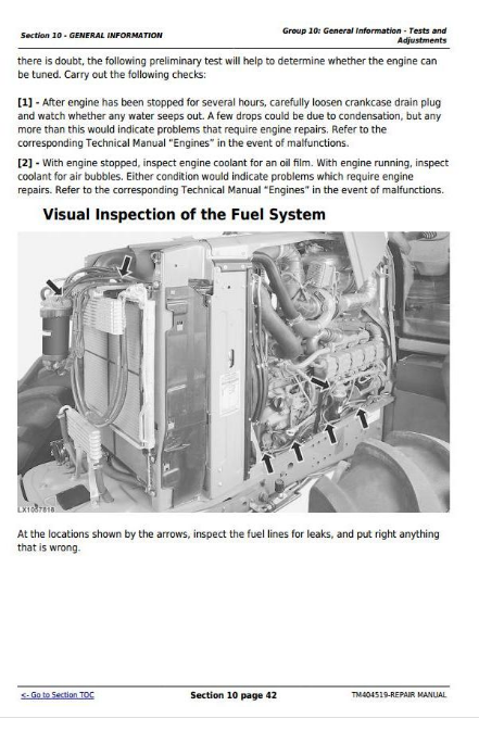
Visual Inspection of the Fuel System
Check the Fuel Filter
Checking the Function of the Fuel Transfer Pump
Bleeding the Fuel System
Installation and Removal of the Primary Air Cleaner Element
Check the Secondary (Safety) Element
Drain Coolant
Check Transmission/Hydraulic System Oil Level
Group 15: General Information - Predelivery Inspection
Predelivery Inspection
Section 20: Engine
Group 00: Engine – Removal and Installation of Components
Engine - Removal and Installation of Components, Summary of References
Engine - Removal and Installation of Components, Special Tools
Engine - Removal and Installation of Components, Repair Specifications
Removing the Engine, Preliminary Work
Engine Removal
Installing the engine
Installing the Engine, Additional Work
Engine Mounting
Replacing the Engine Mountings, Preliminary Work
Replacing the front engine mountings
Replacing the Rear Engine Mountings
Replacing the engine mounting, Further work
Section 30: Fuel, Air-Intake, Cooling and Exhaust Systems
Group 10: Fuel System
Fuel System - Summary of References
Fuel Tank, Removal and Installation
Fuel Level Sensor, Removal and Installation
Bleeding the Fuel System
Group 15: Air Intake System
Air Intake System - Summary of References
B02 - Sensor for Air Cleaner Restriction Warning Light, Removal and Installation
Group 20: Cooling System
Cooling System - Summary of References
Opening Engine Hood
Engine Hood Removal and Installation
Cooler Package Removal and Installation
Charge Air Cooler Removal and Installation
Radiator Removal and Installation
Relieving Drive Belt Tension
Replace the Drive Belt
Routing of Drive Belt
Automatic Belt Tensioner, Removal and Installation
Group 30: Exhaust System
Exhaust System - Summary of References
Special Tools - Summary of References
Exhaust Filter — Handling and Disposal of Ash from the Diesel Particulate Filter
Emission Control System, Important Instructions
Exhaust System to Top Right Removal and Installation
Exhaust Filter - Adjustment
Section 40: Electrical System
Group 05: Electrical System - Connectors
Electrical System - Connectors, Summary of References
Connectors—Special Tools, Summary of References
Installation of the Repair Cable Kit (Smoke and Heat Exhaust System)
General
Using high-pressure washers
Strip Wire Ends
Install Electrical Terminal
WEATHER PACK Connectors
METRI PACK Connector with Terminal Lock at the Rear
METRI PACK Connector with Terminal Lock at the Front
METRI PACK Connectors
Connectors for Electronic Control Units
Connector
CRIMP SNAP IN Connectors
KOSTAL Connectors
DEUTSCH Connectors
Individual Terminals
Bosch™ Connectors
Repair DEUTSCH™ Implement Connectors
Repair Molex™ Connectors
Repair SUMITOMO™ Connectors
Repair YAZAKI™ Connectors
Group 10: Electrical System - Charging Circuit
Electrical System - Charging Circuit, Summary of References
Electrical System - Disconnect the Electrical Circuit
Electrical System - Remove and Install Battery
Electrical System - Alternator Removal and Installation
Group 15: Electrical System - Starter Motor Circuit
Electrical System - Starter Circuit, Summary of References
Electrical System - Starter Removal and Installation
Group 20: Electrical System - Headlights
Electrical System - Lights, Summary of References
General information
Electrical System - Setting Lights
Adjusting Lights on the Cab Frame
Safety Instructions for Replacing a Halogen Bulb
Safety Instructions for Replacing Xenon (HID) Bulbs and Ballast Units
Electrical System - Worklights and Beacon Warning Light, Removal and Installation
Section 45: Electronic Control Units
Group 05: Removal and Installation of Electronic Control Units
Electronic Control Units - Summary of References
Instructions when Replacing a Control Unit
Control Units Location
Roof Control Unit - Removal and Installation
Front Chassis Control Unit (M50) - Removal and Installation
Front Chassis Control Unit (M400) - Removal and Installation
Cab Switch Module Control Unit - Removal and Installation
Engine Control Unit - Removal and Installation
Immobilizer Control Unit - Removal and Installation
Cab Control Unit - Removal and Installation
Air-Conditioning or ClimaTrak™ Control Unit - Removal and Installation
Steering Control Unit (AutoTrac™) - Removal and Installation
Instrument Unit - Removal and Installation
CommandCenter™ Control Unit - Removal and Installation
Rear Chassis Control Unit - Removal and Installation
Control Unit for Power-Assisted Rear PTO Shifting (PAPTOS) - Removal and Installation
Transmission Control Unit (AutoPowr™/IVT™) - Removal and Installation
Group 10: Terminating Resistors - Removal and Installation
Terminating Resistors - Summary of References
A53 - CAN-BUS Terminating Resistor (CAN-BUS - Implement)
A83 - CAN BUS Terminating Resistor (Vehicle CAN BUS (500 kBd))
R021 - CAN BUS Terminating Resistor (CAN BUS Vehicle (500 kBd))
A84 - CAN BUS Terminating Resistor (Vehicle CAN BUS (500 kBd))
R020 - CAN BUS Terminating Resistor (CAN BUS Vehicle (500 kBd))
A131 - CAN BUS Terminating Resistor (Engine CAN Bus)
Section 50A: Drive Train (without Transmission)
Group 00: Drive Train (without Transmission) - Removal and Installation of Components
Drive Train (without Transmission) - Removal and Installation of Components, Summary of References
Drive Systems - Special Tools
Drive Train (without Transmission) - Repair Specifications
Draining Transmission/Hydraulic Oil
Filling System with Transmission/Hydraulic Oil
Remove the Final Drives
Install the Final Drives
Rear PTO Removal
Install the Rear PTO
Removing the Front PTO
Install the Front PTO
Group 10: Drive Train (without Transmission) - Universal-Jointed Shafts and Torsion Dampers
Drive Train (without Transmission) - U.J. Shafts and Torsion Dampers, Summary of References
U-Jointed Shafts and Torsion Dampers - Repair Specifications
U.J. Shafts and Torsion Dampers - Removing the U.J. Shaft (MFWD)
Universal-joint shafts and torsion dampers - Reconditioning the u.j. shaft (MFWD)
U.J. Shafts and Torsion Dampers - Installing the U.J. Shaft (MFWD)
U.J. Shafts and Torsion Dampers - Remove the Engine U.J. Shaft
Universal-Joint Shafts and Torsion Dampers - Installing the Engine Universal-Joint shafts
Universal-Joint Shafts and Torsion Dampers - Removing the Torsion Dampers
Universal-Joint Shafts and Torsion Dampers - Replacing the Torsion Damper Bearing
Universal-Jointed Shafts and Torsion Dampers - Installing the Torsion Damper
Group 15: Drivetrain (without Transmission) - Mechanical Front-Wheel Drive
Drive Train (without Transmission) - Mechanical Front-Wheel Drive, Summary of References
Mechanical Front-Wheel Drive - Special Tools
Mechanical Front-Wheel Drive - Repair Specifications
Mechanical Front-Wheel Drive - Replace the Front-Wheel Drive Axle Speed Sensor
Mechanical Front-Wheel Drive - Reconditioning the MFWD Solenoid Valve
Mechanical Front-Wheel Drive - Sectional View
Mechanical Front Wheel Drive - Exploded View
Removing the Mechanical Front-Wheel Drive
Mechanical Front-Wheel Drive - Removing the FWD Clutch (PowrQuad™ Transmission)
Mechanical Front-Wheel Drive - Remove the Front-Wheel Drive Clutch (AutoPowr™/IVT™ Transmission)
Mechanical Front-Wheel Drive - Repair the Front-Wheel Drive Clutch
Mechanical Front-Wheel Drive - Install the Front-Wheel Drive Clutch (PowrQuad™ Transmission)
Mechanical Front-Wheel Drive - Install the Front-Wheel Drive Clutch (AutoPowr™/IVT™ Transmission)
Mechanical front-wheel drive - Adjusting axial play of output driveshaft
Installing the Mechanical Front-Wheel Drive
Group 20: Drive Train (without Transmission) - Differential
Drive Train (without Transmission) - Differential, Summary of References
Differential - Special Tools
Differential - Repair Specifications
Differential - Handling KJD10672 - Lifting tool for differential
Differential - Replacing the Wheel Speed Sensor
Differential - Replacing Solenoid Valve for Differential Lock
Differential - Sectional View
Differential - Exploded View
Remove the Differential
Recondition the Differential
Install Differential
Differential - Adjusting the Tapered Roller Bearing and Backlash
Group 25: Drive Train (without Transmission) - Hydraulic Pump Drive
Drive Train (without Transmission) - Hydraulic Pump Drive, Summary of References
Hydraulic Pump Drive - Special Tools
Hydraulic Pump Drive - Repair Specifications
Hydraulic Pump Drive - Sectional View
Hydraulic Pump Drive - Exploded View
Removing the hydraulic pump drive
Installing the Hydraulic Pump Drive
Adjusting the Hydraulic Pump Drive
Hydraulic Pump Drive - Check and Adjust the Backlash of the Pump Drive Pinion
Group 30: Drive Train (without Transmission) - Final Drives
Drive Train (without Transmission) - Final Drives, Summary of References
Final Drives - Special Tools
Final Drives - Repair Specifications
Final Drives - Sectional View
Exploded View of Final Drives
Disassemble the Final Drives
Reconditioning the Final Drives
Assemble the Final Drives
Final Drives - Checking and Adjusting Rolling Drag Torque
Group 35: Drive Train (without Transmission) - Rear PTO Options
Drive Train (without Transmission) - Rear PTO Options, Summary of References
Rear PTO Options - Special Tools
Rear PTO Options - Repair Specifications
Rear PTO Options - Replacing the Output Shaft Seal Ring
Rear PTOs - Sectional View
Rear PTO Options - Exploded View
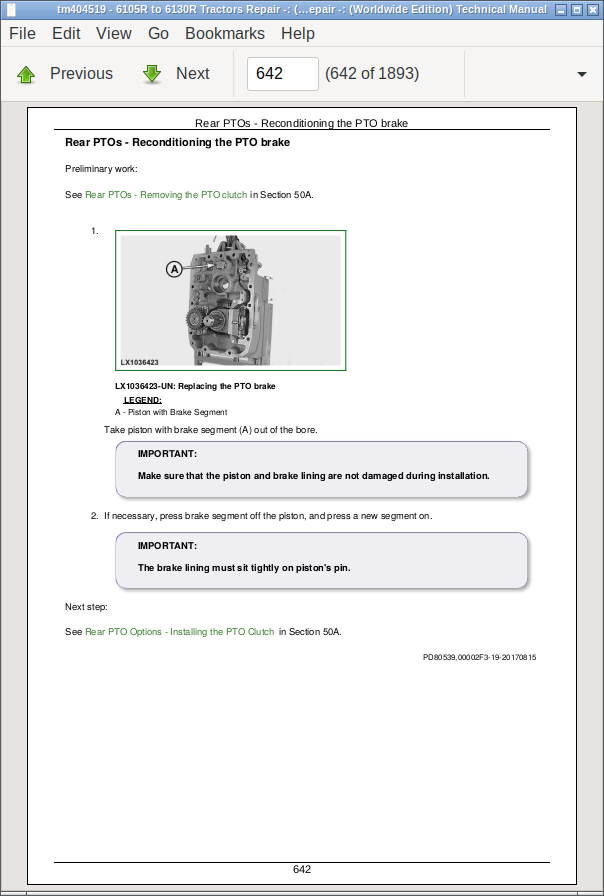
Rear PTO Options - Removing the PTO Clutch
Rear PTO Options - Reconditioning the PTO Clutch
Rear PTOs - Reconditioning the PTO brake
Rear PTO Options - Installing the PTO Clutch
Rear PTO Options - Removing the PTO Drive Train
Rear PTO Options - Reconditioning the Output Shaft
Rear PTO Options - Reconditioning the Countershaft
Rear PTOs - Reconditioning the PTO shifter
Rear PTO Options - Install the PTO Drivetrain
Rear PTO Options - Adjusting the Tapered Roller Bearing of the Countershaft
Rear PTO Options - Adjusting the Tapered Roller Bearing of the Bearing Support
Rear PTO Options - Reconditioning the PTO Shaft Spline Identifier
Rear PTO Options - Replacing Y81 Proportional Solenoid Valve for Rear PTO
Rear PTOs - Replacing B06 sensor for rear PTO speed
Rear PTOs - Reconditioning the oil sight glass
Group 40: Drive Train (without Transmission) - Front PTO for European Tractors
Drive train (without transmission) - Front PTO, Summary of references
Front PTO - Repair Specifications
Front PTO - Sectional View
Front PTO - Exploded view
Front PTO - Changing the Oil Filter
Disassembling the Front PTO
Assemble Front PTO
Front PTO - Replacing the front PTO speed sensor
Front PTO - Replacing the front PTO proportional solenoid valve
Front PTO - Replacing the Oil Cooler
Group 45: Drive Train (without Transmission) - Front Implement Drive
Drive Systems - Front Implement Drive, Summary of References
Front Implement Drive - General Information
Front Implement Drive - Repair Specifications
Front Implement Drive - Exploded View
Removal of the Front Implement Drive
Reconditioning the Front Implement Drive
Installing the Front Implement Drive
Front Implement Drive - Tightening the Clutch Screws (after 100 Operating Hours)
Section 50B: AutoPowr™/IVT™ Transmission
Group 00: AutoPowr™/IVT™ Transmission - Removal and Installation of Components
AutoPowr™/IVT™ Transmission - Removal and Installation of Components, Summary of References
AutoPowr™/IVT™ Transmission - Special Tools
AutoPowr™/IVT™ Transmission - Repair Specifications
Removal of the AutoPowr™/IVT™ Transmission, Preliminary Work
Removing the AutoPowr™/IVT™ Transmission
Installing the AutoPowr™/IVT™ Transmission
Group 05: AutoPowr™/IVT™ Transmission (Repair, Removal and Installation)
AutoPowr™/IVT™ Transmission (Repair, Removal and Installation)
Section 50C: PowrQuad™ Transmission
Group 00: PowrQuad™ Transmission - Removal and Installation of Components
PowrQuad™ Transmission - Removal and Installation of Components, Summary of References
PowrQuad™ Transmission - Installation and Removal of Components, Special Tools
PowrQuad™ Transmission - Removal and Installation of Components, Repair Specifications
PowrQuad™ Plus Transmission, Removal and Installation
AutoQuad™ Plus Transmission, Removal and Installation
Removing the PowrQuad™ Transmission - Preliminary Work
Removing the PowrQuad™ Transmission
Installing the PowrQuad™ Transmission
Remove the Creeper or Option Transmissions
Install the Creeper or Option Transmissions
Remove the Range Transmission
Install the Range Transmission
Group 10: PowrQuad™ Transmission - Transmission Shift Unit
Transmission Shift Controls, Summary of References
PowrQuad™ Transmission - Checking and Adjusting the Shifter and the Park Lock
PowrQuad™ Transmission - Removing the Shift Unit
PowrQuad Transmission - Reconditioning the Shift Unit
PowrQuad™ Transmission - Installing the Shift Unit
PowrQuad™ Transmission - Reconditioning the Clutch Actuation Mechanism
Group 15: PowrQuad™ Transmission - PowrQuad™ Module
PowrQuad™ Transmission - PowrQuad™ Module, Summary of References
PowrQuad™ Transmission - Special Tools, Summary of References
PowrQuad™ Transmission - Repair Specifications
PowrQuad™ Transmission - Transmission Components
PowrQuad™ Transmission - Replacing the Temperature Sensor and Pressure Switches
PowrQuad™ Transmission - Remove and Install the Oil Filter Housing
PowrQuad™ Transmission - Replacing the Oil Filter Housing
PowrQuad™ Transmission - Remove and Install the Front Valve Housing
PowrQuad™ Transmission - Remove and Install the Valves in the Front Valve Housing
PowrQuad™ Transmission - Removing and Installing the Front Transmission Cover
PowrQuad™ Transmission - Removing and Installing the Valves in the Front Transmission Cover
PowrQuad™ Transmission - Remove and Install the Shift Valve Housing
PowrQuad™ Transmission - Remove and Install Valves in Shift Valve Housing
PowrQuad™ Transmission - Remove the Transmission Oil Pump
PowrQuad™ Transmission - Repair the Transmission Oil Pump
PowrQuad™ Transmission - Installing the Transmission Oil Pump
PowrQuad™ Transmission - Removing the Gear-Shift Planetary Drive.
PowrQuad™ Transmission - Repair the Gear-Shift Planetary Drive
PowrQuad™ Transmission - Install the Gear-Shift Planetary Drive
PowrQuad™ Transmission - Removing the B1 Brake Housing
PowrQuad™ Transmission - Reconditioning the B1 Brake
PowrQuad™ Transmission - Installing the B1 Brake Housing
PowrQuad™ Transmission - Removing the B2-B3 Brake Housing
PowrQuad™ Transmission - Reconditioning the B2 Brake
PowrQuad™ Transmission - Reconditioning the B3 Brake
PowrQuad™ Transmission - Installing the B2-B3 Brake Housing
PowrQuad™ Transmission - Removing the C4 Clutch
PowrQuad™ Transmission - Recondition the C4 Clutch
PowrQuad™ Transmission - Install the C4 Clutch
PowrQuad™ Transmission - Removing the Reverse Brake
PowrQuad™ Transmission - Repair the Reverse Brake
PowrQuad™ Transmission - Installing the Reverse Brake
PowrQuad™ Transmission - Removing Forward Clutch with Planetary Drive (Travel Direction)
PowrQuad™ Transmission - Recondition the Forward Clutch with Planetary Drive (Travel Direction)
PowrQuad™ Transmission - Installing Forward Clutch with Planetary Drive (Travel Direction)
PowrQuad™ Transmission - Replacing Clutch Carriers for C4 Clutch and Forward Clutch
PowrQuad™ Transmission - Replace the Transmission Output Shaft and Rear PTO Drive Shaft
Group 20: PowrQuad™ Transmission - Creeper Transmission
PowrQuad™ Transmission - Reconditioning the Creeper Transmission, Summary of References
PowrQuad™ Transmission - Creeper Transmission - Repair Specifications
PowrQuad™ Transmission - Reconditioning the Creeper Transmission
PowrQuad™ Transmission - Creeper Transmission - Reconditioning the Shift Cover
Group 25: PowrQuad™ Transmission - Option Transmission
PowrQuad™ Transmission - Reconditioning the Option Transmission, Summary of References
PowrQuad™ Transmission - Option Transmission - Repair Specifications
PowrQuad™ Transmission - Reconditioning the Option Transmission
Group 30: PowrQuad™ Transmission - Range Transmission
PowrQuad™ Transmission - Range Transmission - Reconditioning, Summary of References
PowrQuad™ Transmission - Repair Specifications
PowrQuad™ Transmission - Range Transmission - Sectional View
PowrQuad™ Transmission - Reconditioning the Range Transmission
PowrQuad™ Transmission - Assembling the Range Transmission
PowrQuad™ Transmission - Reconditioning the Shift Cover
PowrQuad™ Transmission - B104 - Replacing the Transmission Output Speed Sensor
Section 60A: Steering system
Group 10: Steering - Hydrostatic Steering
Steering - Hydrostatic Steering, Summary of References
Hydrostatic Steering - Special Tools, Summary of References
Hydrostatic Steering - Repair Specifications
Hydrostatic Steering - Disconnect/Connect the Steering or Brake Hoses
Hydrostatic Steering - Exploded View
Hydrostatic Steering - Removal and Installation of the Gas-Filled Cylinder
Hydrostatic Steering - Removing the Steering Column
Hydrostatic Steering - Removing the Steering Valve
Hydrostatic Steering - Installing the Steering Valve
Hydrostatic Steering - Install the Steering Column
Group 15: Steering - AutoTrac™
Steering System - AutoTrac™, Summary of References
AutoTrac™ - Repair Specifications
AutoTrac™ - Exploded View
AutoTrac™ - Replacing the Steering Control Valve
AutoTrac™ - Y114-1 - Solenoid Valve for Steering Control Valve (Enable Valve)
AutoTrac™ - Y114-2 - Solenoid Valve for Steering Control Valve (Left Turn)
AutoTrac™ - Y114-3 - Solenoid Valve for Steering Control Valve (Right Turn)
AutoTrac™ - B138 - Replace the Steering Wheel Position Sensor
AutoTrac™ B139 - Removal and Installation of the Steering Angle Sensor
Section 60B: Brakes
Group 10: Brakes - Brake Valve
Brakes - Brake Valve, Summary of References
Brake Valve - Special Tools, Summary of References
Brake Valve - Repair Specifications
Brake Valve - Disconnecting/Connecting Steering or Brake Hoses
Brake Valve - Changing the Accumulator
Brake Valve - Reconditioning the Guide and Piston
Brake Valve - Exploded View
Remove Brake Valve (Power Fill Brakes)
Reconditioning the Power Brake Valve
Install the Power Brake Valve
Remove Power-Fill Brake Valve with MFWD and Disk Brake
Reconditioning the Power Brake Valve with MFWD and Multi-Disk Brake
Installing the Power-Fill Brake Valve with MFWD and Disk Brake
Group 15: Brakes - Rear Brakes
Brakes - Rear Brakes, Summary of References
Rear Brakes - Special Tools, Summary of References
Rear Brakes - Repair Specifications
Rear Brakes - Exploded View
Remove the Rear Brakes
Install the Rear Brakes
Rear Brakes - Replacing the Delay Valve with Shuttle Valve
Rear Brakes - Check Brake Pistons for Return Movement and Leakage
Group 20: Brakes - Hydraulic Trailer Brake
Brakes - Hydraulic Trailer Brake, Summary of References
Hydraulic Trailer Brake - Repair Specifications
Hydraulic Trailer Brake - Repair Instructions
Hydraulic Trailer Brake - Changing the Trailer Brake Valve
Hydraulic Trailer Brake - Change the Coupler
Group 25: Brakes - Air Brake System
Brakes - Air-brake system, Summary of references
Air Brake System - Special Tools, Summary of References
Air-Brake System - Repair Specifications
Air-Brake System - Safety Instructions
Air Brake System - Installing the Compressed-Air Hoses
Air-brake system - Replacing the compressor
Air Brake System - Reconditioning the Compressor
Air-Brake System - Replacing the Compressed-Air Tank
Air-Brake System - Replacing the Trailer Control Valve (for Dual-Line Brakes)
Air-brake system - Replacing the trailer control valve (for single-line brakes)
Air Brake System - Change the Coupling Ends
Group 30: Brakes - Emergency Brake System
Brakes - Auxiliary Brake, Summary of References
Emergency Brake System - Repair Specifications
Emergency Brake - Exploded View
Remove the Emergency Brake
Install the Emergency Brake
Emergency Brake - Replace the Brake Cable
Section 70: Hydraulic System
Group 05: Hydraulic System - General Information
Hydraulic System - General Information, Summary of References
Hydraulic System - General Safety and Repair Information
Group 10: Hydraulic System - Controls
Hydraulic System - Reconditioning the Controls, Summary of References
Repair Specifications
Selective Control Valves (M-SCVs) - Remove and Install the Actuating Elements
Selective Control Valves (M-SCVs) - Adjust the Actuating Cable
Remove and Install Multi-Function Lever (on Shift Console) for M-SCVs at Position 3 and 4 (Edition 1)
Adjust the Multi-Function Lever (on Shift Console) for M-SCVs at Position 3 and 4 (Edition 1)
Remove and Install the Multi-Function Lever (on Shift Console) for M-ICVs (Edition 1)
Adjust Multi-Function Lever (on Shift Console) for M-ICVs (Edition 1)
Remove and Install the Multi-Function Lever (on Shift Console) for M-SCVs at Position 3 and 4 (Version 2)
Adjust the Multi-Function Lever (on Shift Console) for M-SCVs at Position 3 and 4 (Edition 2)
Remove and Install the Multi-Function Lever (on Shift Console) for M-ICVs (Edition 2)
Adjust Multi-Function Lever (on Shift Console) for M-ICVs (Edition 2)
Group 15: Hydraulic System - Oil Filter, Additional Oil Reservoir, Charge Pump, and Hydraulic Pump
Hydraulic System - Oil Filter, Additional Oil Reservoir, Charge Pump and Hydraulic Pump, Summary of References
Repair Specifications
Removal and Installation of the Hydraulic Oil Primary Filter
Hydraulic Oil Filter, Reconditioning
Removal and Installation of the Charge Oil Pump
Charge Oil Pump - Checking the Lube Oil Valve
Hydraulic Pump - Oil Reservoir
Hydraulic Pump - Removal and Installation of the Pressure-and-Flow Regulator
Removal and Installation of the Hydraulic Pump
Removal and Installation of the Additional Oil Reservoir
Group 20: Hydraulic System - Priority 1 to 3 Control Blocks
Hydraulic System - Reconditioning the Priority 1 to 3 Control Blocks, Summary of References
Reconditioning the Priority 1 to 3 Control Blocks - Special Tools, Summary of References
Repair Specifications
Removal and Installation of the Priority 1 Control Block
Reconditioning the Priority 1 Control Block
Removal and Installation of the Control Block with/without Priority 2
Reconditioning the Priority 2 Control Block
Reconditioning the Control Block (without Priority 2)
Removal and Installation of the Priority 3 Control Block
Recondition the Priority 3 Control Block
Group 25: Hydraulic System - Rear Hitch
Hydraulic System - Repair the Rear Hitch, Summary of References
Reconditioning the Rear Hitch - Special Tools, Summary of References
Other Material
Repair Specifications
Rear Hitch - Hitch Valve, Removal and Installation of the Stepper Motor
Rear Hitch - Removal and Installation of the Hitch Valve
Rear Hitch - Recondition the Hitch Valve
Rear Hitch - Removal and Installation of the Position Sensor and Toothed Segment
Rear Hitch - Remove and Install Rockshaft Bearing Block
Rear Hitch - Recondition Rockshaft Bearing Block
Rear Hitch - Removal and Installation of the Lift Cylinders
Rear Hitch - Reconditioning the Lift Cylinders
Rear Hitch - Removal and Installation of the Draft Sensors and Draft Link Bearing Pins
Rear Hitch - Hydraulic Draft Link Stabilizer Bars (HSB) - Removal and Installation of the Control Block
Rear Hitch - Hydraulic Draft Link Stabilizer Bars (HSB), Reconditioning the Control Block
Rear Hitch - Remove and Install Hydraulic Draft Link Stabilizer Bars (HSB)
Rear Hitch - Recondition the Hydraulic Draft Link Stabilizer Bars (HSB)
Rear Hitch - Remove and Install the Hydraulic Center Link (HCL)
Rear Hitch - Recondition the Hydraulic Center Link (HCL)
Group 30: Hydraulic System - Front Hitch
Hydraulic System - Reconditioning the Front Hitch - Summary of References
Repair Specifications
Front Hitch - Remove and Install the Lift Cylinders
Front Hitch - Recondition the Lift Cylinders
Front Hitch - Remove and Install Lift Arm
Front Hitch - Remove and Install Quick Couplers
Group 35: Hydraulic System - Selective Control Valves (SCVs) and Couplers
Repair the Selective Control Valves (SCVs) and Couplers - Summary of References
Repair Specifications
Selective Control Valves (E-SCVs) - Removal and Installation of the Stepper Motors
Removing and Installing the Selective Control Valves (SCVs)
Reconditioning the Selective Control Valves (M-SCVs 100)
Reconditioning the Selective Control Valves (M-SCVs 200)
Reconditioning the Selective Control Valves (M-SCVs 300)
Recondition the Selective Control Valves (M-SCVs 350)
Recondition the Selective Control Valves (M-SCVs 450)
Recondition the Selective Control Valves (E-SCVs 300)
Recondition the Selective Control Valves (E-SCVs 350)
Recondition the Selective Control Valves (E-SCVs 450)
Selective Control Valves (SCVs) - Reconditioning the Couplers
Group 40: Hydraulic System - Independent Control Valves (ICVs)
Repair the Independent Control Valves (ICV) - Summary of References
Repair Specifications
Remove and Install the Independent Control Valves (M-ICVs)
Recondition the Independent Control Valves (M-ICVs)
Independent Control Valves (E-ICV) - Removal and Installation of the Stepper Motors
Remove and Install the Independent Control Valves (E-ICVs)
Recondition the Independent Control Valves (E-ICVs)
Section 80A: Machine-Specific Systems
Group 00: Machine-Specific Systems - Removal and Installation of Components
Machine-Specific Systems - Removal and Installation of Components, Summary of References
Machine-Specific Systems - Special Tools
Machine-Specific Systems - Repair Specifications
Remove the Axle, Preliminary Work
Remove Suspended Front-Wheel Drive Axle
Install Suspended Front-Wheel Drive Axle
Remove the Front-Wheel Drive Axle
Installing the Front-Wheel Drive Axle
Remove Front Axle
Install the Front Axle
Install the Axle, Additional Work
Removing the Front Hitch
Installing the Front Hitch
Remove the Front Axle Support, Preliminary Work
Remove the Front Axle Support for Suspended Front-Wheel Drive Axle
Remove the Front Axle Support for Front-Wheel Drive Axle
Remove Front Axle Support at Front Axle
Installing the Front Axle Support
Install Front Axle Support, Additional Work
Group 10: Machine-Specific Systems – Main Frame
Machine-Specific Systems - Main Frame, Summary of References
Main Frame - Repair Specifications
Main Frame and Attachments
Group 15: Machine-Specific Systems - Front Wheels, Rear Wheels and Fenders
Machine-specific systems - Front wheels, rear wheels, and fender, Summary of references
Front Wheels, Rear Wheels and Fenders - Special Tools
Front Wheels, Rear Wheels and Fenders - Repair Specifications
Front Wheels, Rear Wheels and Fenders - Pivoting Front Fender
Front Wheels, Rear Wheels and Fenders - Removing Front Wheel
Front Wheels, Rear Wheels and Fenders - Reconditioning Front Rim
Front wheels, rear wheels, and fenders - Installing a front wheel
Front Wheels, Rear Wheels and Fenders - Removing the Rear Wheels (with Flanged Axle)
Front Wheels, Rear Wheels and Fenders - Reconditioning the Rear Rim (with Flanged Axle)
Front Wheels, Rear Wheels and Fenders - Installing the Rear Wheel (with Flanged Axle)
Front Wheels, Rear Wheels and Fenders - Removing the Rear Wheel (with Rack-and-Pinion Axle)
Front Wheels, Rear Wheels and Fenders - Reconditioning the Rear Rim (with Rack-and-Pinion Axle)
Front Wheels, Rear Wheels and Fenders - Installing the Rear Wheel (with Rack-and-Pinion Axle)
Front Wheels, Rear Wheels and Fenders - Installing the Reinforced Rear Wheel
Group 20: Machine-Specific Systems – Trailer Hitch and Swinging Drawbar
Machine-Specific Systems - Trailer Hitch and Swinging Drawbar, Summary of References
Repair Specifications
Check the Manually-Operated Hitch for Wear
Check the Manually-Operated Hitch for Wear (Italy and Spain Only)
Check the Remote-Controlled Trailer Hitch for Wear
Trailer Hitch, Checking the Guide Rails
Checking the Tow-Hook for Wear
Checking the Hitch Ball for Wear
Check Drawbar for Wear
Removing and Installing the Center Link Bracket
Removing and Installing the Guide Rails
Reconditioning the Automatic Trailer Hitch
Remote Control for Automatic Trailer Hitch
Reconditioning the Height-Adjustable Trailer Hitch (Italy and Spain Only)
Drawbar
Swinging Drawbar with Pick-Up Hitch
Tightening Torques on High-Clearance Drawbar
Adjusting the High-Clearance Drawbar
Adjusting the Holding Tab
Attaching Safety Decals on the Swinging Drawbar
Group 25: Machine-Specific Systems - Hydraul. Wagon Hitch
Machine-Specific Systems - Hydraulic Pick-Up Hitch, Summary of References
Repair Specifications
Hydraulic Pick-Up Hitch — General Safety and Repair Information
Check Tow Hook on Pick-Up Hitch for Wear
Removing and Installing the Pick-Up Hitch
Pick-Up Hitch - Exploded View
Pick-Up Hitch - Control Lever and Lift Links
Pick-Up Hitch - Hydraulic Parts
Electro-Hydraulic Pick-Up Hitch (E-PUH) - Electro-Hydraulic Parts
Reconditioning the Retainer Spring
Pick-Up Hitch - Recondition the Latch Housing
Recondition the Hydraulic Cylinder
Section 80B: Suspension Systems
Group 10: Suspension Systems - Suspended Front-Wheel Drive Axle
Suspension Systems - Suspended Front-Wheel Drive Axle, Summary of References
Suspension Systems - Special Tools, Summary of References
Repair Specifications
Relieving Hydraulic System Pressure
Removing/Installing the Oscillation Limiter
Remove the Panhard Link
Install the Panhard Link
Removing and Installing Linkage
Removing Position Sensor of Suspended Front-Wheel Drive Axle
Reconditioning Position Sensor of Suspended Front-Wheel Drive Axle
Installing Position Sensor of Suspended Front-Wheel Drive Axle
Remove Hydraulic Cylinder
Recondition the Hydraulic Cylinder
Install Hydraulic Cylinders
Remove the Control Block
Recondition the Valves in the Control Block
Install the Control Block
Removing and Installing the Accumulator
Reconditioning the Accumulator
Remove and Recondition the Bearing Support
Install the Bearing Support
Group 15: Suspension Systems - Cab Suspension
Suspension Systems - Cab Suspension, Summary of References
Important Instructions
Repair Specifications
Relieving Hydraulic System Pressure
Removing and Installing Linkage
Removing and Installing the Cab Position Sensor
Removing and Installing the Accumulator
Reconditioning the Accumulator
Removing and Installing Hydraulic Cylinders
Removing and Installing the Proportional Solenoid Valve
Removing and Installing the Panhard Link
Bleeding Air from the Cab Suspension Hydraulic Cylinders
Section 90: Operator's Cab
Group 00: Operator's Cab - Installation and Removal of Components
Operator's Cab - Removal and Installation of Components, Summary of References
Tilt or Remove the Operator's Cab - Special Tools
Tilting or Removing the Operator's Cab - Screw Torques
Tilt the Operator's Cab Upward and Downward - Special Tools
Tilt the Operator's Cab Upward
Tilting the Operator's Cab Downward
Removing the Operator’s Cab
Installing the Operator's Cab
Group 10: Operator's Cab - Operation and Control Devices
Operator's Cab - Operation and Control Devices, Summary of References
Operation and Control Devices - Replacing an Ignition Key with Chip (Immobilizer)
Operation and Control Devices - Dome Light, Removal and Installation
Operation and Control Devices - Console Lighting, Removal and Installation
Group 15: Operator's Cab - Air-Conditioning System
Operator's Cab - Air-Conditioning System, Summary of References
Air-Conditioning System - Special Tools, Summary of References
Air-Conditioning System - Repair Specifications
Air Conditioning System - Observing AC Hose Torques
Air Conditioning System - Safety at Work
Air Conditioning System - Storage of Refrigerant Containers
Air-Conditioning - Important
Air Conditioning System - Service Work
Air Conditioning System - Preventive Maintenance
Air Conditioning System - Test with Air-Conditioning Service Unit
Air-Conditioning System - Air-Conditioning Service Unit, Filling with Refrigerant Oil
Air conditioning system - Instructions for starting up the DENSO air conditioning compressor
Air-Conditioning System - Leak Test
Air-Conditioning System - Removing the Compressor
Air conditioning system - Checking level in the compressor
Air-Conditioning System - Disassembling the Magnetic Clutch
Air Conditioning System - Checking the Clutch Hub Clearance
Air conditioning system - Installing the compressor
Air Conditioning System - Removing and Installing Condenser
Air Conditioning System - Removing/Installing Receiver-Drier
Air Conditioning System - Access to Components of the Air Conditioning
Air Conditioning System - Remove and Install the Evaporator with Expansion Valve
Air-Conditioning System - Replace Expansion Valve
Air Conditioning System - Installing the Condensation Drain Hoses
Air Conditioning System - Remove and Install the Fan Motor
Air Conditioning System - Removing and Installing the Cab Air Filters
Air Conditioning System - Remove and Install the Interior Filter
Air Conditioning System - Remove and Install the Evaporator Temperature Sensor (B129)
Air Conditioning System - Remove and Install the Refrigerant Pressure Sensor (B130)
Air Conditioning System - Remove and Install the Heater Valve (B131)
Air Conditioning System - Remove and Install the Actuator for Air Distribution (B132)
Air Conditioning System - Remove and Install the ETC Control Unit
Group 20: Operator's Cab - ClimaTrak™
Operators's Cab - ClimaTrak™, Summary of References
ClimaTrak™ - Repair Specifications
ClimaTrak™ - Remove and Install the ATC Control Unit
ClimaTrak™ - Removing and Installing the Ambient Temperature Sensor (Front) (B125)
ClimaTrak™ - Removing and Installing the Ambient Temperature Sensor (Rear) (B126)
ClimaTrak™ - Removing and Installing the Sensor for Inside Air Temperature (B127)
ClimaTrak™ - Removing and Installing the Sensor for Outlet Air Temperature (B128)
ClimaTrak™ - Remove and Install the Refrigerant Pressure Sensor (B130)
ClimaTrak™ - Removing and Installing the Defog Sensor (B143)
ClimaTrak™ - Sensor for Pressure Inside Cab (B213)
ClimaTrak™ - Pressurizer Blower Motor for Pressure Inside Cab (M07)
Group 30: Operator's Cab - Seats
Operator's Cab - Seat, Summary of References
Seat Tools — Summary of References
Repair Specifications
Other Material
General Information on Seat Repairs
Air Comfort Seat MSG95GL, Removal and Installation
Air Comfort Seat MSG95GL, Boot Removal and Installation
Air Comfort Seat MSG95GL - Removal and Installation of Compressor
Air Comfort Seat MSG95GL - Air Spring Removal and Installation
Air Comfort Seat MSG95GL - Seat Suspension Removal and Installation
Air Comfort Seat MSG95GL, Vehicle Connection Harness, Removal and Installation
Air Comfort Seat MSG95GL - Seat Suspension Harness, Removal and Installation
Air Comfort Seat MSG95GL - Actuation for Height Adjustment Removal and Installation
Air Comfort Seat MSG95GL, Check and Adjust the Bowden Cables for Height Adjustment
Air Comfort Seat MSG95GL, Removal and Installation of Bowden Cable for Height Adjustment Downward
Air Comfort Seat MSG95GL, Removal and Installation of Bowden Cable for Height Adjustment Upward
Air Comfort Seat MSG95GL, Level Control Removal and Installation
Air Comfort Seat MSG95GL - Adjust Level Control (Micro-Switch, Vent Valve)
Air Comfort Seat MSG95GL - Air Hoses Removal and Installation
Air Comfort Seat MSG95GL - Air Distributor Removal and Installation
Recondition the CommandARM™
Instructional Seat, Seat Belt Removal and Installation
Group 35: Operator's Cab - Operator's Cab
Operator's Cab, Summary of References
Special Tools - Summary of References
Cab Frame, Removal and Installation
Cab mounting, torques
Rear Post Cover, Removal and Installation
Front Post Cover, Removal and Installation
Storage Compartment, Removal and Installation
Sunshade, Removal and Installation
Panorama Door, Removal and Installation
Panoramic Windshield, Removal and Installation
Adjust the Door Lock
Side Panel, Removal and Installation
Outer Roof, Removal and Installation
Panoramic Roof, Removal and Installation
Section 300: Special Tools
Group 05: General Information
Special Tools - General Information
John Deere Tractors Models 6105R, 6115R, 6125R, 6130R Repair Service Manual (TM404519)
![]()