
John Deere Tractors 6100, SE6100, 6200, SE6200, 6300, SE6300, 6400, SE6400, 6506, 6600 Repair Service Manual (TM4493)
Complete Repair Service Technical Manual for John Deere Tractors 6100, SE6100, 6200, SE6200, 6300, SE6300, 6400, SE6400, 6506, 6600, with workshop information to maintain, repair, and service like professional mechanics.
John Deere 2WD or MFWD Tractors 6100, 6200, 6300, 6400, 6506, 6600, SE6100, SE6200, SE6300 workshop technical manual (repair) includes:
* Numbered table of contents easy to use so that you can find the information you need fast.
* Detailed sub-steps expand on repair procedure information
* Numbered instructions guide you through every repair procedure step by step.
* Notes, cautions and warnings throughout each chapter pinpoint critical information.
* Bold figure number help you quickly match illustrations with instructions.
* Detailed illustrations, drawings and photos guide you through every procedure.
* Enlarged inset helps you identify and examine parts in detail.
tm4493 - 6100 to 6600 tractors Technical Manual.pdf
tm4493 - 6100 to 6600 tractors Technical Manual.epub
Total Pages: 1,916 pages
File Format: PDF/EPUB/MOBI/AZW (PC/Mac/Android/Kindle/iPhone/iPad; bookmarked, ToC, Searchable, Printable)
Language: English
MAIN SECTIONS
Foreword
Safety
Safety Measures
General Information
Specifications
Tune-Up
Predelivery Inspection
Engine
Engine Removal and Installation
Fuel, Air Intake, Cooling and Exhaust Systems
Speed Control Linkage
Fuel System
Air Intake System
Cooling System
Cold Weather Starting Aids
Exhaust System
Electrical System
Connectors
Wiring Harnesses
Charging Circuit
Starting Motor Circuit
Switches, Relays and Solenoids
Monitoring System
Auxiliary Lighting and Electrical Components
Convenience and Accessory Components
SyncroPlus™ Transmission
Removal and Installation of Transmission Components
Summary of Important Specifications
Transmission Shift Controls
PERMA-CLUTCH 2™
Gear Transmission
Creeper Transmission
Option Transmission
Range Transmission
PowrReverserPowrRever™
Removal and Installation of PowrReverser PowrRever™ Module
Transmission Shift Controls
PowrReverserPowrRever™ Module
Gear Transmission
PowrQuad™ Transmission
Removal and Installation of PowrQuad™ Module
Transmission Shift Controls
PowrQuad™ Module
Drive Systems
Component Removal and Installation
U-Jointed Shafts and Torsion Damper
Front Wheel Drive Clutch Up to Transmission Serial No. 114447
Front Wheel Drive Clutch, Transm. Serial No. 114448 to 161066
Front Wheel Drive Clutch from Transmission Serial No. 161067
Differential
Hydraulic Pump Drive
Final Drives
Rear PTO Options
Front PTO
Front Implement Drive
Steering and Brakes
Hydrostatic Steering
Steering Cylinders
Brake Valve
Rear Brakes
Handbrake
Hydraulic Trailer Brake
Air Brakes
Hydraulic System
Controls
Hydraulic Pump and Charge Pump
Hydraulic Pump on SE Tractors
Valves
Valves on SE Tractors
Rockshaft and Rockshaft Cylinder
Three-Point Hitch
Selective Control Valves and Couplers
Independent Control Valve
Miscellaneous
Component Removal and Installation
Main Frame
Front Axle
Front and Rear Wheels
Trailer Hitch
Pick-Up Hitch up to Tractor Serial No. 176448
Pick-Up Hitch From Tractor Serial No. 176449
Swinging Drawbar
Operator's Cab and 4-Post Roll Guard
Tilting, Removing and Installing the Operator's Cab
Tilting, Removing and Installing the Operator's Cab (SE Tractors)
Controls and Instruments
Electronic Hitch Control Components
Air-Conditioning System
Heating System (6100-6600)
Heating System (SE Tractors)
Operator's Cab
Seats
Radio
Special Tools (Dealer-Fabricated)
Special Tools (Dealer-Fabricated)
tm4493 - 6100 to 6600 tractors
Table of Contents
Foreword
Section 05: Safety
Group 05: Safety Measures
Recognize Safety Information
Prevent Machine Runaway
Handle Fluids Safely-Avoid Fires
Prevent Battery Explosions
Prepare for Emergencies
Prevent Acid Burns
Avoid High-Pressure Fluids
Park Machine Safely
Support Machine Properly
Wear Protective Clothing
Work in Clean Area
Service Machines Safely
Work In Ventilated Area
Illuminate Work Area Safely
Replace Safety Signs
Use Proper Lifting Equipment
Construct Dealer-Made Tools Safely
Avoid Heating Near Pressurized Fluid Lines
Remove Paint Before Welding or Heating
Safety Information - Air Brake System
Avoid Eye Contact with Radar
Keep ROPS Installed Properly
Service Tires Safely
Practice Safe Maintenance
Use Proper Tools
Dispose of Waste Properly
Live With Safety
Service Front-Wheel Drive Tractor Safely
Section 10: General Information
Group 05: Specifications
Specifications
Diesel Engine Oil
Transmission and Hydraulic Oil
Front Wheel Drive Axle Oil
Diesel Engine Coolant
Grease
Oil Filters
Mixing of Lubricants
Alternative and Synthetic Lubricants
Lubricant Storage
Unified Inch Bolt and Cap Screw Torque Values
Metric Bolt and Cap Screw Torque Values
Serial Number Plates
Product Identification Number and Component Serial Numbers
Group 10: Tune-Up
Specifications
Using High-Pressure Washers
Preliminary Engine Test
Tractor Tune-Up
Checking Fuel Filter
Bleeding the Fuel System
Neutral Start Circuit
Neutral Start Circuit
Final Engine Check
Tractor Operation Check
Group 15: Predelivery Inspection
Predelivery Inspection
Section 20: Engine
Group 00: Engine Removal and Installation
Special or Essential Tools
Specifications
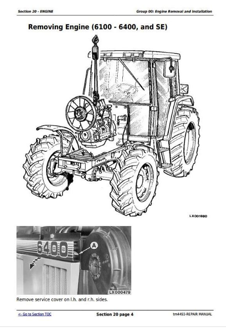
Removing Engine (6100 - 6400, and SE)
Installing the Engine
Bleeding Fuel System
Installing the Engine (6506 and 6600)
Installing the Engine
Replacing the Engine Mountings (6100 to 6400, and SE)
Replacing the Engine Mountings (6506 and 6600)
Front Engine Mountings
Rear Engine Mountings
Section 30: Fuel, Air Intake, Cooling and Exhaust Systems
Group 05: Speed Control Linkage
Specifications
Adjusting Throttle Hand Lever and Pedal
Adjusting Speed Control Linkage
Exploded View of Hand Throttle Lever (On Older Tractors)
Exploded View of Hand Throttle Lever (On Newer Tractors)
Exploded View of Accelerator Pedal
Exploded View of Accelerator Pedal (SE Tractors with Low Profile Cab)
Group 10: Fuel System
Special Tool (Dealer-Manufactured)
General Information
Removing Fuel Tank
Installing Fuel Tank
Replacing the Fuel Gauge Sending Unit
Replacing Fuel Transfer Pump
Bleeding the Fuel System
Changing Fuel Filter
Group 15: Air Intake System
General Information
Air Intake System - 6100 to 6400 Tractors
Air Intake System - 6506 and 6600 Tractors
Group 20: Cooling System
General Information
Specifications
Removing Radiator
Replacing Fan and Viscous Fan Drive
Installing Radiator
Relieving Drive Belt
Replacing Drive Belt
Replacing Drive Belt Tensioner
Repairing Drive Belt Tensioning Device
Aligning the Hydraulic Drive Belt Tensioner From tractor serial no. 107753 to 152341
Hydraulic Drive Belt Tensioner Up to tractor serial no. 159438 - Exploded View
Hydraulic Drive Belt Tensioner From tractor serial no. 107753 to 152341 - Exploded View
Group 25: Cold Weather Starting Aids
Fuel Preheater
Electric Starting Aid
Coolant Heater
Group 30: Exhaust System
Specifications
Installing the Muffler
Installing the Muffler Pipe
Installing the Exhaust Pipe
Replacing the Auxiliary Muffler
Replacing the Exhaust Pipe
Installing the Exhaust Pipe
Section 40: Electrical System
Group 05: Connectors
Special or Essential Tools
General Information
Disconnecting Electrical Circuit
METRI PACKMETRI PACK is a trademark of Packard Electric.. Connector
WEATHER PACKWEATHER PACK is a trademark of Packard Electric Connector
CRIMP SNAP INCRIMP SNAP IN is a trademark of the AMP Company. Connector
CPCCPC is a trademark of AMP Inc. Connector
Replace Load Center Connector
Replace Power Distribution Center Connectors
Replacing Female Terminal on 45-Pin Plug
Installing Terminal
Changing Terminals
Stripping Wire Ends
Installing Terminal
Group 10: Wiring Harnesses
Ground Point Locations
Removing and Installing Engine Wiring Harness
Removing and Installing Cab Wiring Harness (Without HMS)
Removing and Installing Cab Wiring Harness (With HMS)
Removing and Installing Cab Wiring Harness (With Electrical Reverser Control)
Removing and Installing Cab Wiring Harness (SE Tractors)
Removing and Installing 4-Post ROPS Harness
Removing and Installing Wiper and Air-Conditioning Harness
Removing and Installing Fan Wiring Harness (SE Tractors)
Removing and Installing Cab Roof Wiring Harness
Removing and Installing Cab Roof Wiring Harness (SE Tractors)
Removing and Installing Transmission Wiring Harness
Removing and Installing Transmission Wiring Harness (With Electrical Reverser Control)
Group 15: Charging Circuit
Repair Alternator-Use CTM
General
Specifications
Removing Alternator
Relieving Drive Belt
Group 20: Starting Motor Circuit
Special or Essential Tools
Specifications
Repair Starter-Use CTM
Removing the Starting Motor
Group 25: Switches, Relays and Solenoids
Disconnecting Electrical Circuit
Specifications
Replace Stop Light Switch
Removing and Installing the Thermostat Switch up to Tractor Serial No. 170 667
Removing and Installing the Thermostat Switch From Tractor Serial No. 170 668Not SE tractors
Removing and Installing the Thermostat Switch From SE Tractors
Removing and Installing the High/Low Pressure Switch
Replacing Blower Switch
Replacing Blower Switch on SE Tractors
Replacing Air Conditioning Switch
Removing HMS (Headland Management System) Switch
Remote Control of Rockshaft and PTO
Replace MFWD Switch
Differential Lock Switch
Replace PTO Switch
Replace Hitch Control Potentiometer and Switch
Replacing the Sensitivity Potentiometer
Replacing the Position Sensor
Removing the Draft Sensor
Replacing the Neutral Start Switch
Replace Main Switch
Replace Light Switch and Hazard Warning Light Switch
Replacing the Work Light Switch
Replace Switches on Multi-Function Unit (Tractors Without Electrical Reverser Control)
Replace Switches on Multi-Function Unit (Tractors With Electrical Reverser Control)
Replace Dome Light Switch
Replacing the Coil on the Solenoid Valve (Front-Wheel Drive)
Replacing the Coils on the Solenoid Valves of the Differential Lock and Rear PTO
Replacing the Coils on the Solenoids for Electrical Reverser Control
Replace Fuel Shut-Off Solenoid
Replacing the Starting Motor Relay
Main Fuses
Fuse Box (Load Center) 1 (6100-6400 Tractors Up to Serial No. 127538)
Fuse Box (Load Center) 2 (6100-6400 Tractors Up to Serial No. 127538)
Fuse Box (Load Center) 1 (6100-6400 Tractors From Serial No. 127539)
Load Center 2 (6100-6400 Tractors From Serial No. 127539)
Fuse Box (Load Center) 1 (6600 Tractors Up to Serial No. 139832)
Fuse Box (Load Center) 2 (6600 Tractors Up to Serial No. 139832)
Fuse Box (Load Center) 1 (6600 With or without HMS from serial no. 139833 and 6100-6506With performance monitor and/or HMS Tractors)
Load Center 2 (6600With or without HMS from serial no. 139833 and 6100-6506With performance monitor and/or HMS Tractors)
Group 30: Monitoring System
Special Tool (Dealer-Manufactured)
Disconnecting Electrical Circuit
Replace PTO Speed Sending Unit
Replacing Engine Oil Pressure Sending Unit
Replacing Engine Speed Sending Unit
Replacing Air Cleaner Sending Unit
Replacing Coolant Temperature Sending Unit
Replacing the Fuel Gauge Sending Unit
Replace Speed Sending Unit
Replacing Overvoltage Protection
Temperature and Pressure Sending Units
Removing Instrument Unit
Group 40: Auxiliary Lighting and Electrical Components
Replace Seven-Terminal Outlet Socket
Replace Three-Terminal Outlet Socket
Group 45: Convenience and Accessory Components
Disconnecting Electrical Circuit
Removing and Installing Fan and Radiator
Removing and Installing Fan and Radiator on SE Tractors
Replace Wiper Motor
Section 50: Transmission
Group 00: Removal and Installation of Transmission Components
Special or Essential Tools
Dealer-Manufactured Special Tools
Specifications
Removing Clutch Housing
Installing Clutch Housing
Removing Gear Transmission
Installing Gear Transmission
Removing Creeper or Option Transmissions
Installing Creeper or Option Transmissions
Removing Range Transmission Housing
Installing Range Transmission Housing
Group 01: Summary of Important Specifications
Summary of Important Specifications
Group 05: Transmission Shift Controls
Specifications
Gear Shift Linkage (Up to Tractor Serial No. 182777)
Range Shift Linkage (Up to Tractor Serial No. 182777)
Gear Shift Linkage (From Tractor Serial No. 182778)
Range Shift Linkage (From Tractor Serial No. 182778)
Adjusting Shift Linkage and Parking Lock (Up to Tractor Serial No. 182777)
Adjusting Shift Linkage and Parking Lock (From Tractor Serial No. 182778)
Clutch Pedal Adjustment (Up to Tractor Serial No. 130420)
Clutch Pedal Adjustment (From Tractor Serial No. 130421)
Group 10: PERMA-CLUTCH 2PERMA-CLUTCH 2 is a trademark of Deere & Company.
Special or Essential Tools
Specifications
Preliminary Work
Removing Clutch
Removing the Transmission Oil Pump
Transmission Oil Pump Components
Assembling the Transmission Oil Pump
Installing the Transmission Oil Pump
Disassembling Clutch
Exploded View of Clutch
Assembling Clutch
Installing the Clutch
Final Assembly
Valves
Engagement Override Valve
Clutch Cooling Valve
Clutch Cooling Pilot Valve
Filter Relief Valve
Pressure Regulating Valve
Lube Relief Valve
Cooler Relief Valve
Removing Clutch Pedal Valve
Installing Clutch Pedal Valve
Solenoid ValveUp to component serial no. 102256
Clutch Cooling Sending Unit Up to component serial no. 102256
Temperature and Pressure Sending Units
Test Ports
Group 15: Gear Transmission
Special or Essential Tools
Specifications
Preliminary Work
Disassembling Gear Shift Transmission
Assembling Drive Shaft
Installing Shafts
Final Assembly
Measuring the Gaps at the Connecting Ring
Installing Transmission Housing
Adjusting Shifting Mechanism
Adjusting Neutral Start Switch
Checking Neutral Start Switch
Group 20: Creeper Transmission
Specifications
Creeper Transmission
Preliminary Work
Disassembling Creeper Transmission
Assembling Creeper Transmission
Shift Linkage - Sectional View
Installing the Shift Linkage
Repairing the Shift Cover
Final Assembly
Group 25: Option Transmission
Specifications
Option Transmission
Preliminary Work
Disassembling Option Transmission
Assembling Countershaft
Installing Shafts
Final Assembly
Adjusting Shifter Fork
Group 30: Range Transmission
Specifications
Range Transmission-Sectional Views
Preliminary Work
Disassembling Range Transmission
Exploded View of Differential Drive Shaft
Exploded View of Countershaft and Parking Lock
Exploded View of Shift Mechanism
Repairing the Shift Cover
Assembling Range Transmission
Cone Point Adjustment
Adjusting Shift Mechanism
Final Assembly
Section 51:
Group 00: Removal and Installation of PowrReverser PowrReverser is a trademark of Deere & Company. Module
Special or Essential Tools
Dealer-Manufactured Special Tools
Specifications
Removing the PowrReverser PowrReverser is a trademark of Deere & Company. Module
Installing the PowrReverser PowrReverser is a trademark of Deere & Company. Module
Removing and Installing the Gear Transmission
Group 05: Transmission Shift Controls
Specifications
Forward/Reverse Linkage
Range Shift Linkage
Gear Shift Linkage
Adjusting the Reverse Drive Linkage
Adjusting the Shift Linkage and Parking Lock
Clutch Pedal Adjustment
Group 10: PowrReverserPowrReverser is a trademark of Deere & Company. Module
Special or Essential Tools
Specifications
PowrReverserPowrReverser is a trademark of Deere & Company. Module - Sectional View
Components of Power Train
Preliminary Work
Repair Instructions
Removing the Disk Brake
Removing the Clutch and Planet Carrier
Removing the Transmission Oil Pump
Disassembling the Transmission Oil Pump
Exploded View of Transmission Oil Pump
Assembling the Transmission Oil Pump
Installing the Transmission Oil Pump
Disassembling the Clutch and Planet Carrier
Exploded View of Clutch and Planet Carrier
Assembling the Clutch and Planet Carrier
Installing the Clutch and Planet Carrier
Exploded View of Disk Brake
Repairing and Installing the Disk Brake
Final Assembly
Valves and Other Hydraulic Components
Repair Instructions
Replacing the Oil Filter
Repairing the Pressure Regulating Valve
Repairing the Cooling Pilot Valve
Repairing the Clutch Cooling Valve
Repairing the Engagement Override Valve
Repairing the Filter Relief Valve
Repairing the Cooler Relief Valve
Repairing the Lube Relief Valve
Repairing the Sump Valve
Repairing the Accumulator Piston
Repairing the Forward/Reverse Valve
Repairing the Fwd/Rev Cooling Control Valve
Repairing the Modulator Valve
Repairing the Connecting Valve
Repairing the Clutch Pedal Valve
Repairing the Temperature and Pressure Sending Units
Replacing the Neutral Start Switch
Test Ports
Group 15: Gear Transmission
Special Tool (Dealer-Manufactured)
Specifications
Preliminary Work
30 km/h (18.5 mph) Gear Transmission
40 km/h (25 mph) Gear Transmission
Disassembling the Gear Transmission
Assembling the Drive Shaft
Installing Shafts
Final Assembly
Measuring the Gaps at the Connecting Ring
Installing Transmission Housing
Adjusting the Shift Mechanism
Section 55: Transmission
Group 00: Removal and Installation of PowrQuad PowrQuad is a trademark of Deere & Company. Module
Special or Essential Tools
Dealer-Manufactured Special Tools
Special Tool (Dealer-Fabricated)
Specifications
Removing the PowrQuad PowrQuad is a trademark of Deere & Company. Module
Installing the PowrQuad PowrQuad is a trademark of Deere & Company. Module
Group 05: Transmission Shift Controls
Specifications
Gear Shift Linkage (Reverser Control on Switch Console) Up to Tractor Serial No. 182335 (4-Cyl.) or 184326 (6-Cyl.)
Range Shift Linkage (Reverser Control on Switch Console) Up to Tractor Serial No. 182335 (4-Cyl.) or 184326 (6-Cyl.)
Gear Shift Linkage (Reverser Control on Switch Console) From Tractor Serial No. 182336 (4-Cyl.) or 184327 (6-Cyl.)
Range Shift Linkage (Reverser Control on Switch Console) From Tractor Serial No. 182336 (4-Cyl.) or 184327 (6-Cyl.)
Gear Shift Linkage (Reverser Control on Steering Column)
Range Shift Linkage (Reverser Control on Steering Column)
Adjusting the Reverse Drive Linkage
Adjusting Shift Linkage and Parking Lock - Reverser Control on Switch Console
Adjusting the Shift Linkage and Parking Lock - Reverser Control on Switch Console
Adjusting the Shift Linkage and Parking Lock - Reverser Control on Steering Column
Clutch Pedal Adjustment (Up to Tractor Serial No. 130420)
Clutch Pedal Adjustment (From Tractor Serial No. 130421)
Group 10: PowrQuadPowrQuad is a trademark of Deere & Company. Module
Special or Essential Tools
Service Equipment and Tools
Other Material
Specifications
Transmission Components
Install Transmission in Repair Stand
Remove Transmission Front Cover/Front Valve Housing
Remove Front Valve Housing
Valves in Front Valve Housing
Valves in the Front Transmission Cover
Removing the Clutch Pedal Valve
Installing the Clutch Pedal Valve
Transmission Pump-Cross-Sectional View
Repair Transmission Pump
Install Front Valve Housing
Installing the Front Valve Housing
Install Transmission Front Cover/Front Valve Housing
Remove Shift Control Valve Housing
Replace Forward-Reverse/Speed Selector Shifter Levers/Shaft Seals
Replace Forward-Reverse/Speed Selector Shifter Shafts/Shifter Arms
Valves in Shift Valve Housing (Older Tractor Series)
Modulator Valve - Cross-Sectional View
Planetary Housing Valves
Forward/Reverse Control Valve - Cross-Sectional View (Older Tractor Series)
Forward/Reverse Control Valve - Cross-Sectional View (Newer Tractor Series)
Forward/Reverse Control Valve - Cross-Sectional View (Electrical Reverser Control)
Speed Valve - Cross-Sectional View (Older Tractor Series)
Speed Valve - Cross-Sectional View (Newer Tractor Series)
Assembling and Installing the Shift Valve Housing (Older Tractor Series)
Assembling and Installing the Shift Valve Housing (Newer Tractor Series)
Disassemble Planetary/Reverse Brake Housing Assembly
Recondition Input Planetary Carrier
Input Planetary Assembly-Cross-Sectional View
Disassemble Reverse Brake Housing Components
Reverser Carrier/Vehicle Clutch Assembly - Cross-Section
Recondition Reverser Carrier/Traction Clutch Assembly
Disassemble Planetary Housing Components
Direct Drive Clutch Assembly-Cross-Sectional View
Recondition Direct Drive Clutch Assembly
Assemble Planetary Housing Components
Assemble Reverse Brake Housing Components
Assemble Planetary/Reverse Brake Housing Assembly
Section 56: Drive Systems
Group 00: Component Removal and Installation
Special or Essential Tools
Dealer-Fabricated Tool
Specifications
Removing Front Wheel Drive Clutch
Installing Front Wheel Drive Clutch
Removing Differential Housing
Installing Differential Housing
Removing Final Drives
Installing the Final Drives
Removing Rear PTO
Installing PTO Housing
Removing Front PTO
Installing the Front PTO
Group 05: U-Jointed Shafts and Torsion Damper
Specifications
Removing U.J. Shaft (FWD)
Installing U.J. Shaft (FWD)
Removing U.J. Shaft (Engine)
Removing the Torsion Damper
Installing the Torsion Damper
Installing the U.J. Shaft (Engine)
Disassemble Universal Jointed Drive Shaft
Assembling Jointed Shaft
Group 10A: Front Wheel Drive Clutch Up to Transmission Serial No. 114447
Special Tool (Dealer-Manufactured)
Specifications
Preliminary Work
Disassembling Front Wheel Drive Clutch
Assembling Front Wheel Drive Clutch
Final Assembly
Group 10B: Front Wheel Drive Clutch, Transm. Serial No. 114448 to 161066
Special Tool (Dealer-Fabricated)
Specifications
Preliminary Work
Disassembling Front Wheel Drive Clutch
Assembling Front Wheel Drive Clutch
Final Assembly
Group 10C: Front Wheel Drive Clutch from Transmission Serial No. 161067
Special Tool (Dealer-Manufactured)
Specifications
Preliminary Work
Disassembling Front Wheel Drive Clutch
Assembling Front Wheel Drive Clutch
Final Assembly
Group 15: Differential
Specifications
Preliminary Work
Removing Differential
Disassembling Differential Housing
Assembling the Differential
Installing Differential
Adjusting Taper Roller Bearing
Adjusting Backlash
Final Assembly
Group 20: Hydraulic Pump Drive
Special or Essential Tools
Specifications
Pump Drive Specifications
Removing Pump Drive
Pump Drive - Sectional View
Installing Pump Drive
Final Assembly
Adjusting the Pump Drive
Group 25: Final Drives
Special or Essential Tools
Specifications
Preliminary Work
Disassembling Final Drives
Assembling Final Drives
Adjusting Rear Axle Rolling Drag Torque
Final Assembly
Group 30: Rear PTO Options
Special or Essential Tools
Special Tools (Dealer Fabricated)
Specifications
Replacing Output Shaft Seal Ring
Changing the O-Ring on Reversible PTO
Removing PTO Housing
PTO (540 1/min) - Sectional View
PTO (540/1000 rpm Reversible) - Cross-Sectional View
PTO (540/1000 rpm Shiftable and 540/540E/1000 rpm)
Removing PTO Clutch
Repairing the PTO Clutch
Adjusting Play at Hub
Installing PTO Clutch
Replacing PTO Brake
Output Shaft (540 1/min) - Sectional View
Output Shaft and Countershaft (540/1000 rpm Reversible) - Cross-Sectional View
Output Shaft and Countershaft (540/1000 rpm Shiftable and 540/540E/1000 rpm)
Disassembling PTO Drive Train
Repairing the Output Shaft
Output Shaft (540/1000 rpm Reversible)
Repairing the Output Shaft
Output Shaft (540/1000 rpm Shiftable, 540/540E/1000 rpm)
Countershaft (540/1000 and 540/540E/1000 rpm)
Assembling the PTO Shifter (540/1000 rpm Shiftable and 540/540E/1000 rpm)
Assembling PTO Drive Train
Adjusting Taper Roller Bearing at Output Shaft
Adjusting Taper Roller Bearings at Output Shaft
Adjusting Taper Roller Bearing of Countershaft
Adjusting Taper Roller Bearings
Installing PTO Housing
Removing the PTO Modulating Valve
Repairing the PTO Modulating Valve
Installing the PTO Modulating Valve
Repairing the Solenoid Valve
Replacing PTO Speed Sending Unit If equipped
PTO Shifting Parts
Changing and Adjusting the Bowden Cable
Adjusting the Indicator Light Switch
Group 35: Front PTO
Special or Essential Tools
Specifications
Front PTO (Running Clockwise)
Front PTO (Running Counterclockwise)
Front PTO - Sectional View
Removing Front PTO Shaft
Disassembling Front PTO Shaft
PTO (Clockwise Running) - Exploded View
PTO (Counterclockwise Running) - Exploded View
PTO Clutch and Brake - Clockwise Running PTO
PTO Clutch and Brake - Counterclockwise Running PTO
Front PTO Housing
Assembling Front PTO
Determining Preload of Input Shaft and PTO Shaft Taper Roller Bearings
Installing Front PTO Shaft
Repairing Solenoid Valve
Oil Lines
Group 40: Front Implement Drive
Special or Essential Tools
Specifications
Front Implement Drive - Exploded View
Changing the Driver
Replacing the Damper
Section 60: Steering and Brakes
Group 05: Hydrostatic Steering
Special or Essential Tools
Specifications
Preliminary Work
Removing the Steering Valve (Without Steering Column)
Removing Steering Column and Steering Valve
Steering Valve- Exploded View
Repairing Steering Valve
Disassembling the Steering Valve
Exploded View of Steering Valve
Assembling the Steering Valve
Adjusting Double-Acting Shock Valves
Steering Wheel and Steering Column (6100 to 6600 Tractors With Cab)
Steering Wheel and Steering Column (SE Tractors and Tractors Without Cab)
Repairing the Steering Column
Installing Steering Valve (Without Steering Column)
Installing Steering Column and Steering Valve
Group 10: Steering Cylinders
General Information
Special or Essential Tools
Special Tools
Specifications
Removing Steering Cylinder
Disassembling Steering Cylinder
Assembling Steering Cylinder
Installing Steering Cylinder
Group 15: Brake Valve
Special or Essential Tools
Specifications
Checking Brake Piston Travel
Preliminary Work
Removing the Control Valve
Checking Valve Seat
Peening the Valve Seat
Measuring Thickness of Shim
Bleeding the Brake Valve
Checking Opening Pressure of Control Valve
Adjusting the Stop Light Switch
Final Assembly
Repair Kit AL70575
Removing Brake Valve
Brake Valve - Sectional View
Disassembling Brake Valve
Assembling the Brake Valve
Installing Brake Valve
Adjusting Brake Pedals
Bleeding the Brakes
Adjusting the Stop Light Switch
Final Assembly
Group 20: Rear Brakes
Special or Essential Tools
Specifications
Removing Rear Brakes
Installing Rear Brake
Checking Brake Pistons for Return Movement and Leakage
Final Assembly
Bleeding the Brakes
Group 25: Handbrake
Specifications
Preliminary Work
Removing the Handbrake
Installing Handbrake
Final Assembly
Handbrake Components
Replacing the Handbrake Cable
Handbrake Test
Adjusting Handbrake
Group 30: Hydraulic Trailer Brake
Special or Essential Tools
Specifications
Repair Information
Replacing Trailer Brake Valve
Cleaning Trailer Brake Valve
Cleaning the Screen
Replacing the Check Valve
Bleeding the Trailer Brake Valve
Checking Trailer Brake Valve
Group 35: Air Brakes
Special or Essential Tools
Specifications
General Information
Installing the Screw Unions
Changing the Compressor
Gaskets for the Compressor
Changing the Compressed Air Tank
Changing the Pressure Control Valve
Changing the Pressure Control Valve
Changing the Pressure-Limiting Valve
Changing the Trailer Control Valve
Changing the Pressure Gauge
Changing the Coupling Ends
Test Sequence
Leak Test
Checking the Handbrake (Dual-Line Brakes)
Checking the Handbrake (Single-Line Brakes)
Adjusting the Handbrake
Checking the “Supply” Coupling End
Section 70: Hydraulic System
Group 05: Controls
General Information
Specifications
Replacing the Bowden Cable
Connecting the Bowden Cable
Adjusting the Bowden Cable
Installing the Multi-Function Lever
Adjusting Multi-Function Lever
Group 10: Hydraulic Pump and Charge Pump
Service Equipment and Tools
Other Material
Specifications
Repair Instructions
Removing the Charge Pump
Disassembling Charge Pump
Assembling Charge Pump
Installing the Charge Pump
Checking the Lube Oil Valve
Restrictor in Oil Tank
Check Valve in Oil Leak-Off Line
Changing the Hydraulic Pump Controller
Hydraulic Pump Controller-Exploded View
Disassemble, Inspect, and Assemble Hydraulic Controller
Adjusting the Controller
Removing the Hydraulic Pump
Installing Hydraulic Pump
Hydraulic Pump 40 cm3 (2.4 cu.in) - Exploded View
Hydraulic Pump 25 cm3 (1.5 cu.in) - Exploded View
Disassemble, Inspect and Assemble Hydraulic Pump
Adjust Swashplate Bearing Preload
Adjust Shaft Bearing Preload 40 cm3 (2.4 cu.in) Pump
Group 11: Hydraulic Pump on SE Tractors
Specifications
Repair Instructions
Removing the Hydraulic Pump
Exploded View
Repairing the Hydraulic Pump
Removing the Installation Plate
Changing the Lube Valve
Installing the Installation Plate
Installing the Hydraulic Pump
Group 15: Valves
Special or Essential Tools
Special Tools (Dealer Fabricated)
Specifications
Repair Instructions
Direct Control of Rockshaft
Removing the Rockshaft Valve
Repairing Rockshaft Valve
Depth to Which Pressure and Discharge Valves are Screwed In
Changing the Stepper Motor
Centering the Stepper Motor
Installing Rockshaft Valve
Installing the Shuttle Valves
Shuttle Valve with Hydraulic Trailer Brake
Shuttle Valve with Independent Control Valve
Removing the Main Block
Repairing the Main Block - Exploded View
Checking the Check Valve If equipped
Installing the Main Block
Checking Oil Filter Head
Filter Relief Valve
Power Beyond Application Valve - Exploded View (New Version)
Power Beyond Application Valve - Exploded View (Old Version)
Connecting the Power Beyond Application Valve
Adjusting the Power Beyond Application Valve
Converting the Power Beyond Application Valve
Connecting the Power Beyond Application Valve
Adjusting the Power Beyond Application Valve
Group 16: Valves on SE Tractors
Note
Specifications
Repair Instructions
Installing Shuttle Valves on SE Tractors
Shuttle Valve with Hydraulic Trailer Brake
Removing the Main Block
Repairing the Main Block - Exploded View
Checking the By-Pass Valve
Checking the Priority Inlet Valve
Changing the Pressure Limiting Valve For steering pressure
Changing the Pressure Relief Valve For system (engagement) pressure
Installing the Main Block
Checking the Filter By-Pass Valve and Oil Filter Head
Changing the Lube Valve
Group 20: Rockshaft and Rockshaft Cylinder
Specifications
Electronic Hitch Control Unit (HCU)
Removing Position Sensor and Toothed Segment
Attaching the Toothed Segment
Assembling the Position Sensor
Installing the Position Sensor
Removing Rockshaft
Assembling Rockshaft
Removing Rockshaft Cylinders
Repairing Rockshaft Cylinder
Changing the Rockshaft Cylinder Gasket
Assembling Rockshaft Cylinder
Installing Rockshaft Cylinder
Group 25: Three-Point Hitch
Special or Essential Tools
Self-Manufactured Special Tools
Specifications
Removing Draft-Sensing Pins or Draft Link Bearing Pins
Assembling Draft-Sensing Pins
Installing the Draft-Sensing Pin
Checking and Adjusting the Draft Sensor
Automatic Stabilizer Rod (Left-Hand)
Adjustable Stabilizer Rod (Left-Hand)
Adjustable Stabilizer Rod (Right-Hand)
Group 30: Selective Control Valves and Couplers
Special Tools (Dealer Fabricated)
Other Material
Specifications
Repair Instructions
SCV Identification
Removing Selective Control Valves
Series 100/101 Selective Control Valve - Exploded View
Repairing the Selective Control Valve - 100/101 Series
Series 200/201 Selective Control Valve-Exploded View
Series 300/301 Selective Control Valve-Exploded View
Replace Control Knobs
Inspect Poppet Load-Check Valves
Inspect Pressure Compensator Valve-300/301 Series
Inspect Metering Valve-300/301 Series
Inspect Metering Valve-200/201 Series
Repairing the Control Valve-300/301 Series
Repairing the Control Valve-200/201 Series
Installing Selective Control Valves
Installing the Shuttle Valves
Installing Shuttle Valves on SE Tractors
Installing the Left-Hand Endplate
Installing the Right-Hand Endplate
Adjustment of Pressure Limit at Selective Control Valves (300 Series)
Changing Couplers
Deluxe Coupler - Exploded View
Repairing the Deluxe Coupler
Checking Couplers for Leaks
Group 35: Independent Control Valve
Specifications
Repair Instructions
Removing the Independent Control Valve
Repairing the Independent Control Valve
Changing the Pressure-Limiting Valve
Assembling the Independent Control Valve
Installing the Independent Control Valve
Section 80: Miscellaneous
Group 00: Component Removal and Installation
Special or Essential Tools
Dealer-Manufactured Special Tools
Dealer-Fabricated Tool
Specifications
Removing the Main Frame, 6100-6400 Tractors, and SE Tractors
Installing Main Frame
Removing Main Frame, 6506 and 6600 Tractors
Installing the Main Frame
Removing Front Axle
Installing Front Axle
Removing Front Wheel Drive Axle
Installing Front Wheel Drive Axle
Removing Front Axle Support (6506 and 6600 Tractors)
Installing Front Axle Support
Group 05: Main Frame
Specifications
Removing and Installing the Main Frame
Group 10: Front Axle
General Information
Specifications
Removing Front Axle
Dissassembling Front Axle
Assembling Front Axle
Adjusting Knuckle and Spindle Assembly Axial Play
Assembling Wheel Hub
Adjusting Wheel Bearings
Assembling Axle Center Section
Installing Front Axle
Installing Tie-Rod
Checking Front Wheel Toe-In
Adjusting Front Wheel Toe-In
Group 15: Front and Rear Wheels
Special or Essential Tools
Specifications
Removing a Wheel (Front or Rear)
Assembling Rear Wheel (With Rack-and-Pinion Axle)
Attaching Cast Rim
Attaching Front Wheel
Attaching Rear Wheel
Group 20: Trailer Hitch
Specifications
Installing Rigid Trailer Mounting
Installing Guide Rails
Trailer Mounting (Height-Adjustable, 4-Position)
Trailer Mounting (Height-Adjustable, 9-Position)
Repairing the Automatic Trailer Hitch
Remote Control for Automatic Trailer Hitch
Adjusting the Remote Control
Functional Check
Group 25A: Pick-Up Hitch up to Tractor Serial No. 176448
Specifications
Installing Upper Frame
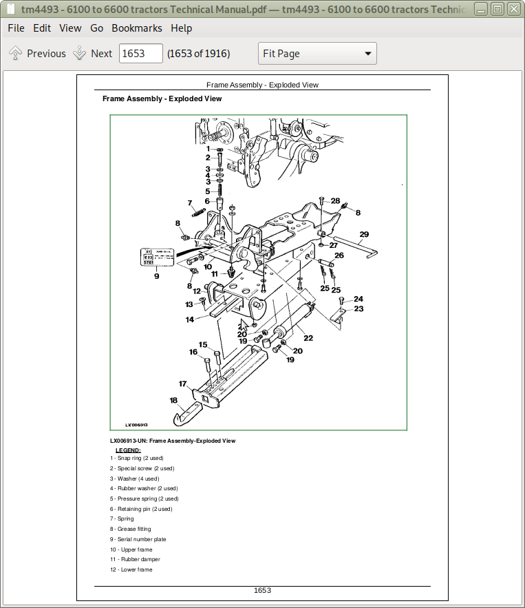
Frame Assembly - Exploded View
Operating Lever and Lift Links - Exploded View
Hydraulic Parts
Repairing Hydraulic Cylinder
Adjusting Lift Links
Adjusting Guide Stop
Changing the Bowden Cable
Adjusting the Bowden Cable
Operational Check
Group 25B: Pick-Up Hitch From Tractor Serial No. 176449
Specifications
Installing Upper Frame
Frame Assembly - Exploded View
Operating Lever and Lift Links - Exploded View
Hydraulic Parts
Repairing the Retainer Spring
Repairing the Latch Housing
Repairing Hydraulic Cylinder
Adjusting the Lift Links
Adjusting the Guide Stop
Operational Check
Group 30: Swinging Drawbar
Torques for Hardware - Swinging Drawbar
Torques for Hardware - Swinging Drawbar With Pick-Up Trailer Hitch
Adjusting the Retaining Strap
Section 90: Operator's Cab and 4-Post Roll Guard
Group 00: Tilting, Removing and Installing the Operator's Cab
Special or Essential Tools
Dealer-Manufactured Special Tools
Specifications
4-Post Roll Guard
Tilting the Cab Upward
Tilting the Operator's Cab Downward
Clutch Pedal Adjustment (Up to Tractor Serial No. 130420)
Clutch Pedal Adjustment (From Tractor Serial No. 130421)
Removing the Operator's Cab
Installing Operator's Cab
Group 01: Tilting, Removing and Installing the Operator's Cab (SE Tractors)
Special or Essential Tools
Dealer-Manufactured Special Tools
Specifications
Tilting Flat-Floor Cabs on SE Tractors
Tipping Up Low Profile Cabs on SE Tractors
Tilting the Cab Up
Tilting the Operator's Cab Downward
Clutch Pedal Adjustment (From Tractor Serial No. 130421)
Removing the Operator's Cab from SE Tractors
Installing the Operator's Cab on SE Tractors
Group 05: Controls and Instruments
Disconnecting Electrical Circuit
Removing the Control Panel
Replacing a Bulb on the Control Panel
Replacing Bulbs on the Instrument Unit
Replacing Basic Control Module (BCU)
Replacing Reverser Control Unit (RCU) Not SE tractors
Adjusting the Instrument Unit
Adjusting Digital Control
Group 10: Electronic Hitch Control Components
Disconnecting Electrical Circuit
Replacing the Hitch Control Unit (HCU)
Replacing the Operation Unit
Group 15: Air-Conditioning System
Special or Essential Tools
Specifications
Torques for Tightening Refrigerant Hoses
Safety at Work
Handling Refrigerant
In an Emergency
Safety Equipment
Storage of Refrigerant Containers
R134a Refrigerant
Important
Discharging the System On SE tractors, the high/low pressure switch is located at the rear of the operator's cab. The procedure for “Discharging The System” is nonetheless the same.
Evacuating the System On SE tractors, the high/low pressure switch is located at the rear of the operator's cab. The procedure for “Evacuating The System” is nonetheless the same.
Filling with Refrigerant Oil On SE tractors, the high/low pressure switch is located at the rear of the operator's cab. The procedure for “Filling With Refrigerant Oil” is nonetheless the same.
Filling the System On SE tractors, the high/low pressure switch is located at the rear of the operator's cab. The procedure for “Filling The System” is nonetheless the same.
Topping up a Partly Discharged System On SE tractors, the high/low pressure switch is located at the rear of the operator's cab. The procedure for “Topping Up A Partly Discharged System” is nonetheless the same.
Leak Test
Removing the Compressor
Checking Level in the Compressor
Disassembling the Compressor Clutch
Checking Clutch Hub Clearance
Checking the Compressor Manifold
Installing the Compressor
Removing and Installing the Condenser
Removing and Installing the Receiver-Drier
Removing and Installing the Evaporator and Expansion ValveNot SE tractors
Replacing the Expansion Valve
Removing and Installing the Evaporator and Expansion Valve on SE Tractors
Installing Condensation Water Drain Hoses Not SE tractors
Arrangement of Condensation Water Drain Hoses on SE Tractors
Removing the Heater/Evaporator Housing from SE Tractors
Removing and Installing the Thermostat Switch Up to Tractor Serial No. 170667
Removing and Installing the Thermostat Switch From Tractor Serial No. 170668Not SE tractors
Adjusting Thermostat Switch Bowden Cables Not SE tractors
Removing and Installing the Thermostat Switch From SE Tractors
Removing and Installing the High/Low Pressure Switch
Group 20: Heating System (6100-6600)
Ventilator and Heater, Exploded View
Removing and Installing Fan and Radiator
Removing and Installing Heater Valve Up to Serial No. 171080
Removing and Installing Heater Valve From Serial No. 171081
Adjusting Bowden Cables of Heater Valve
Removing the Cab Air Filter
Group 21: Heating System (SE Tractors)
Ventilator and Heater, Exploded View
Removing the Cab Air Filter
Removing and Installing Fan and Radiator
Removing and Installing the Heater Valve
Removing the Heater/Evaporator Housing
Group 25: Operator's Cab
Specifications
Removing Cab Frame
Removing and Installing the Cab Bearings (6100-6400 and SE Tractors)
Removing and Installing the Cab Bearings (6506-6600)
Installing Windshield
Installing Rear Window
Adjusting Window Contact Pressure
Removing Cab Door
Installing Cab Door
Installing Door Lock
Installing Door Holding Bracket
Replacing Handrail or Rear View Mirror
Removing Hatch
Removing Outer Roof
Removing the Inner Section of the Roof
Removing Inner Roof Trim
Group 30: Seats
Specifications
Comfort Seat DS44-07, Exploded View
Comfort Seat DS44-06, Exploded View
Super Comfort Seat S85/90-05, Exploded View - Upper Section
Super Comfort Seat DS85H1-02, Exploded View - Lower Section
Air Comfort Seat MSG95A-00, Lower Section
Passenger Seat, Exploded View
Group 35: Radio
Radio, Loudspeakers and Aerial, Exploded View
Section 99: Special Tools (Dealer-Fabricated)
Group 05: Special Tools (Dealer-Fabricated)
Lifting Device
Lifting Device
Holding Tool
Wooden Prism
Driver
Assembly and Guide Mandrels
Turning Device
Suspension Eyes for Operator's Cab
Holding Device
Bushing
Spring Compressor
Bushing
Socket Wrench Insert
Special Key
DFRW79-Piston Holding Tool
John Deere Tractors 6100, SE6100, 6200, SE6200, 6300, SE6300, 6400, SE6400, 6506, 6600 Repair Service Manual (TM4493)
![]()