
John Deere Tractors 6100D, 6110D, 6115D, 6125D, 6130D, 6140D Diagnosis and Tests Service Technical Manual (TM605119)
Complete Diagnosis & Tests Technical Manual with electrical wiring diagrams for John Deere 2WD or MFWD 6100D, 6110D, 6115D, 6125D, 6130D, 6140D (November 2011), with all the shop information to maintain, diagnose, and rebuild like professional mechanics.
John Deere 2WD or MFWD Tractors 6100D, 6110D, 6115D, 6125D, 6130D, 6140D workshop Diagnosis & Tests technical manual includes:
* Numbered table of contents easy to use so that you can find the information you need fast.
* Detailed sub-steps expand on repair procedure information
* Numbered instructions guide you through every repair procedure step by step.
* Troubleshooting and electrical service procedures are combined with detailed wiring diagrams for ease of use.
* Notes, cautions and warnings throughout each chapter pinpoint critical information.
* Bold figure number help you quickly match illustrations with instructions.
* Detailed illustrations, drawings and photos guide you through every procedure.
* Enlarged inset helps you identify and examine parts in detail.
tm605119 - 6100D, 6110D, 6115D, 6125D, 6130D, and 6140D Tractors, Diagnostic Technical Manual (November 2011).pdf
tm605119 - 6100D, 6110D, 6115D, 6125D, 6130D, and 6140D Tractors, Diagnostic Technical Manual (November 2011).epub
Total Pages: 1,896 pages
File Format: PDF/EPUB/MOBI/AZW (PC/Mac/Android/Kindle/iPhone/iPad; bookmarked, ToC, Searchable, Printable)
Language: English
MAIN SECTIONS
Foreword
General
Safety
Tractor Specifications and Component Identification
Serial Number Locations
Diagnostic and Testing Procedures
Electrical System Operational Checkout
Power Train System Operational Checkout
Mechanical Front Wheel Drive System Operational Checkout
Brake System Operational Checkout
Selective Control Valve System Operational Checkout
Rockshaft System Operational Checkout
Steering Operational Checkout
Diagnostic Trouble Codes
Engine Control Unit Diagnostic Trouble Codes
Chassis Control Unit Diagnostic Trouble Codes
Power Reverser Transmission Diagnostic Trouble Codes
Instrument Cluster Controller Diagnostic Trouble Codes
Observable Symptoms
Engine Operation and Tests
Fuel and Air Operation and Tests
Electrical System Diagnosis and Tests
Power Train Operation and Tests
Mechanical Front Wheel Drive System Diagnosis and Tests
Brake System Diagnosis and Tests
Hydraulic System Diagnosis and Test
Steering System Diagnosis and Tests
Operator Station Diagnosis and Tests
Engine System Diagnosis and Tests
Engine Diagnostics General Information
Test Procedures and Adjustments
Cooling System
Component Information
Fuel/Air Operation and Tests
General Information
Test Procedures and Adjustments
Air Intake System Diagnostics
Fuel System Diagnosis 4045
Component Information
Electrical System Diagnostics and Tests
General Information
Component Identification
Accessing Diagnostic Codes and Addresses
Calibration Procedures
Diagnostic Trouble Codes
Diagnostic Addresses
PTR Component Tests
Air Conditioning and Heater Diagnostics
Air Filter Restriction Indicator Diagnostics
Air Intake Heater Diagnostics
Auxiliary Power Diagnostics
Back-Up Alarm Diagnostics
CAN Bus Diagnostics
Charging System Diagnostics
Control Unit Power Diagnostics - ECU
Control Unit Power Diagnostics - EHC
Dome Light Diagnostics
Engine Coolant Temperature Diagnostics
Engine Fuel Control Electrical Diagnostics
Engine Oil Pressure Diagnostics
Fuel Level Diagnostics
Fuel Shut-Off Diagnostics (Rotary Injection Pump)
Horn Diagnostics
Instrument Panel Diagnostics (Deluxe)
Instrument Panel Diagnostics (Standard)
Brake Light Diagnostics
Road Lights Diagnostics
Turn Signal Diagnostics
Warning Lights Diagnostics
Work Lights Diagnostics
Power Distribution Diagnostics
Power Train - Reverser Electrical Diagnostics
Power Train - Wet Clutch Electrical Diagnostics
PTO Indicator Diagnostics
Radio Diagnostics
Starting System - Injection Pump Advance Timing Diagnostics
Starting System Diagnostics
Trailer Outlet (7-Pin) Diagnostics
Wiper Diagnostics
Secondary Brake Switch Diagnostics
Circuit Code Listing
Connector Information
Power Train Diagnosis and Tests
General Information
Test Procedures and Adjustments
Dry Traction Clutch Diagnostics
Wet Traction Clutch Diagnostics
Power Reverser Diagnostics
Power Reverser transmission Gearbox Diagnostics
Collar Shift Transmission Diagnostics
Top Shaft Synchronized (TSS) Transmission Diagnostics
Component Information
Drive Systems Diagnosis and Tests
General Information
MFWD Diagnostics
Power Take Off (PTO) Diagnostics
Differential and Final Drive Diagnostics
Component Information
Brake System Diagnosis and Test
General Information
Test Procedures and Adjustments
Brake System Diagnostics
Component Identification
Hydraulic System Diagnosis and Tests
General Information
Test Procedures and Adjustments
Basic Hydraulic System Overall Diagnostics
Rockshaft System Diagnostics
Rear Mount Selective Control Valve System Diagnostics
Mid Mount Selective Control Valve System Diagnostics
Hydraulic Trailer Brake Valve System Diagnostics
Component Information
Steering System Diagnosis and Tests
General Information
Test Procedures and Adjustments
Steering System Diagnostics
Component Information
Operator Station Diagnosis and Tests
General Information
Test and Adjustment Procedures
Air Conditioning and Heating Diagnostics
Seat Diagnostics
Component Location
Service Tools
Dealer Fabricated Tools
Service Tools and Kits
tm605119 - 6100D, 6110D, 6115D, 6125D, 6130D, and 6140D Tractors, Diagnostic Technical Manual (November 2011)
Table of Contents
Foreword
Section 210: General
Group 05: Safety
Recognize Safety Information
Understand Signal Words
Follow Safety Instructions
Prevent Machine Runaway
Keep ROPS Installed Properly
Work In Ventilated Area
Handle Fluids Safely—Avoid Fires
Prepare for Emergencies
Wear Protective Clothing
Handle Chemical Products Safely
Stay Clear of Rotating Drivelines
Practice Safe Maintenance
Park Machine Safely
Support Machine Properly
Remove Paint Before Welding or Heating
Avoid Heating Near Pressurized Fluid Lines
Avoid High-Pressure Fluids
Service Cooling System Safely
Prevent Acid Burns
Prevent Battery Explosions
Service Tires Safely
Dispose of Waste Properly
Use Proper Lifting Equipment
Construct Dealer-Made Tools Safely
Work in Clean Area
Illuminate Work Area Safely
Service Machines Safely
Use Proper Tools
Wait Before Opening High-Pressure Fuel System
Handle Starting Fluid Safely
Protect Against High Pressure Spray
Clean Vehicle of Hazardous Pesticides
Live With Safety
Group 10: Tractor Specifications and Component Identification
General Specifications
Overall Dimensions and Weights
Turning Radius—2WD Axle
Turning Radius—MFWD Axle
Ground Speeds—Collar Shift (CST) or Top Shaft Synchronized (TSS) Transmission
Ground Speeds—PowrReverser™ Transmission (PRT)
Metric Bolt and Screw Torque Values
Unified Inch Bolt and Screw Torque Values
Sealants and Adhesives Cross-Reference Chart
How To Dispense/Apply/Assemble Gasket Sealants
Face Seal Fittings Assembly and Installation—All Pressure Applications
Metric Face Seal Fitting Torque Chart—Standard Pressure Applications
SAE Face Seal Fitting Torque Chart—Standard Pressure Applications
Metric Face Seal Fitting Torque Chart—High Pressure Applications
SAE Face Seal Fitting Torque Chart—High Pressure Applications
Group 15: Serial Number Locations
Serial Numbers
Product Identification Number
Engine Serial Number Location
Fuel Injection Pump Serial Number Location
Transaxle Serial Number Location
MFWD Serial Number Location (If Equipped)
Cab Serial Number Location
Group 20: Diagnostic and Testing Procedures
General Troubleshooting Information
Group 40: Electrical System Operational Checkout
Electrical System Operational Checkout
Group 50: Power Train System Operational Checkout
Power Train System Operational Checkout
Group 55: Mechanical Front Wheel Drive System Operational Checkout
Mechanical Front Wheel Drive System Operational Checkout
Group 60: Brake System Operational Checkout
Brake System Operational Checkout
Group 70: Selective Control Valve System Operational Checkout
Selective Control Valve System Operational Checkout
Group 75: Rockshaft System Operational Checkout
Rockshaft System Operational Checkout
Group 80: Steering Operational Checkout
Steering Operational Checkout
Section 211: Diagnostic Trouble Codes
Group ECU: Engine Control Unit Diagnostic Trouble Codes
ECU 000029.03 - Throttle Number 2 Signal Out of Range High
ECU 000029.04 - Throttle Number 2 Signal Out of Range Low
ECU 000091.03 - Throttle Number 1 Signal Out of Range High
ECU 000091.04 - Throttle Number 1 Signal Out of Range Low
ECU 000097.03 - Water-in-Fuel Signal Out of Range High
ECU 000097.04 - Water-in-Fuel Signal Out of Range Low
ECU 000097.16 - Water-in-Fuel Detected
ECU 000100.01 - Engine Oil Pressure Signal Extremely Low
ECU 000100.04 - Engine Oil Pressure Signal Out of Range Low
ECU 000105.00 - Intake Manifold Air Temperature Signal Extremely High
ECU 000105.03 - Intake Manifold Air Temperature Signal Out of Range High
ECU 000105.04 - Intake Manifold Air Temperature Signal Out of Range Low
ECU 000105.15 - Intake Manifold Air Temperature Signal Slightly High
ECU 000105.16 - Intake Manifold Air Temperature Signal Moderately High
ECU 000108.02 - Barometric Pressure Signal Invalid
ECU 000110.00 - Engine Coolant Temperature Signal Extremely High
ECU 000110.03 - Engine Coolant Temperature Signal Out of Range High
ECU 000110.04 - Engine Coolant Temperature Signal Out of Range Low
ECU 000110.15 - Engine Coolant Temperature Signal Slightly High
ECU 000110.16 - Engine Coolant Temperature Signal Moderately High
ECU 000157.03 - Fuel Rail Pressure Signal Out of Range High
ECU 000157.04 - Fuel Rail Pressure Signal Out of Range Low
ECU 000157.10 - Fuel Rail Pressure Rate of Change Abnormal
ECU 000157.17 - Fuel Rail Pressure Not Developed
ECU 000158.17 - ECU Power Down Error
ECU 000174.00 - Fuel Temperature Signal Extremely High
ECU 000174.03 - Fuel Temperature Signal Out of Range High
ECU 000174.04 - Fuel Temperature Signal Out of Range Low
ECU 000174.16 - Fuel Temperature Signal Moderately High
ECU 000189.00 - Engine Speed Derate Condition Exists
ECU 000611.03 - Injector Shorted to Power
ECU 000611.04 - Injector Shorted to Ground
ECU 000627.01 - All Injector Circuits Have High Resistance
ECU 000629.12 - ECU EEPROM Error
ECU 000636.02 - Camshaft Sensor Signal Invalid
ECU 000636.05 - Camshaft Sensor Circuit Has High Resistance
ECU 000636.06 - Camshaft Sensor Circuit Has Low Resistance
ECU 000636.08 - Camshaft Sensor Signal Missing
ECU 000636.10 - Camshaft Signal Rate of Change Abnormal
ECU 000637.02 - Engine Timing Sensor Signal Invalid
ECU 000637.05 - Engine Position Sensor Circuit Has High Resistance
ECU 000637.06 - Engine Position Sensor Circuit Has Low Resistance
ECU 000637.07 - Engine Timing and Position Signals Out of Sync
ECU 000637.08 - Engine Timing Sensor Signal Missing
ECU 000637.10 - Crank Timing Signal Rate of Change Abnormal
ECU 000651.00 - Injector Number 1 Data Extremely High
ECU 000651.01 - Injector Number 1 Data Extremely Low
ECU 000651.02 - Injector Number 1 Part Number Data Invalid
ECU 000651.05 - Injector Number 1 Circuit Has High Resistance
ECU 000651.06 - Injector Number 1 Circuit Has Low Resistance
ECU 000651.07 - Injector Number 1 Not Responding
ECU 000651.13 - Injector Number 1 Calibration Fault
ECU 000652.00 - Injector Number 2 Data Extremely High
ECU 000652.01 - Injector Number 2 Data Extremely Low
ECU 000652.02 - Injector Number 2 Part Number Data Invalid
ECU 000652.05 - Injector Number 2 Circuit Has High Resistance
ECU 000652.06 - Injector Number 2 Circuit Has Low Resistance
ECU 000652.07 - Injector Number 2 Not Responding
ECU 000652.13 - Injector Number 2 Calibration Fault
ECU 000653.00 - Injector Number 3 Data Extremely High
ECU 000653.01 - Injector Number 3 Data Extremely Low
ECU 000653.02 - Injector Number 3 Part Number Data Invalid
ECU 000653.05 - Injector Number 3 Circuit Has High Resistance
ECU 000653.06 - Injector Number 3 Circuit Has Low Resistance
ECU 000653.07 - Injector Number 3 Not Responding
ECU 000653.13 - Injector Number 3 Calibration Fault
ECU 000654.00 - Injector Number 4 Data Extremely High
ECU 000654.01 - Injector Number 4 Data Extremely Low
ECU 000654.02 - Injector Number 4 Part Number Data Invalid
ECU 000654.05 - Injector Number 4 Circuit Has High Resistance
ECU 000654.06 - Injector Number 4 Circuit Has Low Resistance
ECU 000654.07 - Injector Number 4 Not Responding
ECU 000654.13 - Injector Number 4 Calibration Fault
ECU 001136.00 - ECU Temperature Signal Extremely High
ECU 001136.16 - ECU Temperature Signal Moderately High
ECU 001347.03 - High Pressure Fuel Pump Control Valve Signal Out of Range High
ECU 001347.05 - High Pressure Fuel Pump Solenoid Circuit Has High Resistance
ECU 001347.07 - High Pressure Fuel Pump Not Able to Meet Required Rail Pressure
ECU 001569.31 - Engine Power Derate Condition Exists
ECU 003509.03 - Sensor Supply Number 1 Voltage Out of Range High
ECU 003509.04 - Sensor Supply Number 1 Voltage Out of Range Low
ECU 003510.03 - Sensor Supply Number 2 Voltage Out of Range High
ECU 003510.04 - Sensor Supply Number 2 Voltage Out of Range Low
ECU 003511.03 - Sensor Supply Number 3 Voltage Out of Range High
ECU 003511.04 - Sensor Supply Number 3 Voltage Out of Range Low
ECU 524225.31 - Engine Start Protection Bypass Detected
Group CCU: Chassis Control Unit Diagnostic Trouble Codes
CCU 000100.01 - Engine Oil Pressure Signal Extremely Low
CCU 000100.04 - Engine Oil Pressure Signal Out of Range Low
CCU 000110.00 - Engine Coolant Temperature Signal Extremely High
CCU 000110.03 - Engine Coolant Temperature Sensor Out of Range High
CCU000110.04 - Engine Coolant Temperature Sensor Out of Range Low
CCU 000161.02 - Reverse Sun Gear Speed Sensor Fault
CCU 000629.12 - Control Unit Fault
CCU 001638.00 - Hydraulic Oil Temperature Very Hot
CCU 001638.03 - Hydraulic Oil Temperature Sensor Circuit Voltage High
CCU 001638.04 - Hydraulic Oil Temperature Sensor Circuit Voltage Low
CCU 001638.16 - Hydraulic Oil Temperature High
CCU 002818.31 - Operator Presence Switch Not Activated
CCU 003509.03 - Sensor Supply Voltage Out of Range High
CCU 003509.04 - Sensor Supply Voltage Out of Range Low
CCU 523839.02 - Hand Brake Switch Conflict
CCU 524016.04 - CCU Switched Supply Voltage Low
Group PTR: Power Reverser Transmission Diagnostic Trouble Codes
PTR 000158.01 - System Switched Voltage Low
PTR 000190.18 - Engine Not Running During Neutral to Gear Shift
PTR 000598.02 - Clutch Disengaged Switch or Clutch Pedal Sensor Circuit Conflict
PTR 000598.04 - Clutch Not Disengaged Signal Failed Low
PTR 000628.02 - Program Memory Data Erratic, Intermittent, or Incorrect
PTR 000629.12 - PTR Control Unit Fault
PTR 000734.05 - Forward Solenoid Valve Circuit Fault
PTR 000735.05 - Reverse Solenoid Valve Circuit Fault
PTR 000752.03 - Power Shuttle Sensor Voltage Out Of Range High
PTR 000752.04 - Power Shuttle Sensor Voltage Out Of Range Low
PTR 000761.00 - Excessive Pressure at Inactive Forward Clutch
PTR 000761.03 - Transmission Forward Range Pressure Indicator Voltage Above Normal, or Shorted to High Source
PTR 000761.04 - Transmission Forward Range Pressure Indicator Voltage Below Normal, or Shorted to Low Source
PTR 000763.00 - Excessive Pressure at Inactive Reverse Clutch
PTR 000763.03 - Transmission Reverse Range Pressure Indicator Voltage Above Normal, or Shorted to High Source
PTR 000763.04 - Transmission Reverse Range Pressure Indicator Voltage Below Normal, or Shorted to Low Source
PTR 001504.10 - Seat Switch Failed Active
PTR 002820.31 - Operator Not Seated During a Directional Reverser Lever Command
PTR 003509.03 - Sensor Supply Voltage High
PTR 003509.04 - Sensor Supply Voltage Low
PTR 523959.31 - No Wheel Speed While in Gear
PTR 523960.31 - Operator Not Present During Reverser Command Not Available or Condition Exists
PTR 524020.31 - Power Up Without Neutral Not Available or Condition Exists
PTR 524021.31 - Reverser Lever Switch Fault
PTR 524160.02 - Not Neutral Signal Conflicts with Neutral Signal
PTR 524173.02 - Clutch Pedal Compare Error
PTR 524173.13 - Clutch Pedal Position Out of Calibration
PTR 524173.15 - Clutch Pedal Sensor Out Of Range High
PTR 524173.16 - Clutch Pedal Sensor Out Of High Normal Range
PTR 524173.17 - Clutch Pedal Sensor Out Of Range Low
PTR 524173.18 - Clutch Pedal Sensor Out Of Low Normal Range
PTR 524230.05 - Enable Solenoid Circuit Fault
PTR 524230.07 - Clutch Not Engaging
PTR 524234.03 - Clutch Enable Pressure Sensor Circuit Voltage Out Of Range High
PTR 524234.04 - Clutch Enable Pressure Sensor Circuit Voltage Out Of Range Low
PTR 524254.03 - Transmission Enable Signal High
PTR 524254.04 - Transmission Enable Signal Low
Group ICC: Instrument Cluster Controller Diagnostic Trouble Codes
ICC 000107.00 - Engine Air Filter 1 Differential Pressure Data Valid but Above Normal Operational Range - Most Severe Level
ICC 000167.04 - Alternator Voltage Below Normal, or Shorted to Low Source
ICC 000628.12 - Program Memory Bad Intelligent Device or Component
ICC 000630.02 - Calibration Memory Data Erratic, Intermittent or Incorrect
Section 212: Observable Symptoms
Group 220: Engine Operation and Tests
Engine System Diagnostics
Group 230: Fuel and Air Operation and Tests
Air Intake System Diagnostics
Fuel System Diagnostics
Group 240: Electrical System Diagnosis and Tests
Air Conditioning and Heater Electrical Diagnostics
Air Filter Restriction Indicator Diagnostics
Air Intake Manifold Heater Diagnostics
Auxiliary Power Diagnostics
Back-Up Alarm Diagnostics
CAN Bus Diagnostics
Charging System Diagnostics
Control Unit Power Diagnostics - ECU
Control Unit Power Diagnostics - EHC
Dome Light Diagnostics
Engine Coolant Temperature Diagnostics
Engine Fuel Control Electrical Diagnostics
Engine Oil Pressure Diagnostics
Fuel Level Diagnostics
Horn Diagnostics
Instrument Panel Diagnostics - Deluxe
Instrument Panel Diagnostics - Standard
Lighting System Diagnostics - Brakes
Lighting System Diagnostics - Road Lights
Lighting System Diagnostics - Turn Signals
Lighting System Diagnostics - Warning Lights
Lighting System Diagnostics - Work Lights
Power Distribution System Diagnostics
Power Train—Reverser Diagnostics (Electrical)
Power Train—Wet Clutch Diagnostics (Electrical)
PTO Indicator Diagnostics
Radio Diagnostics
Starting System Diagnostics
Trailer Outlet (7-Pin) Diagnostics
Wiper Diagnostics
Group 250: Power Train Operation and Tests
Dry Traction Clutch Diagnostics
Wet Traction Clutch Diagnostics
Power Reverser Diagnostics
Power Reverser Transmission Gearbox Diagnostics
Collar Shift Transmission Diagnostics
Top Shaft Synchronized (TSS) Transmission Diagnostics
Group 255: Mechanical Front Wheel Drive System Diagnosis and Tests
Mechanical Front Wheel Drive Diagnostics
Power Take Off (PTO) Diagnostics
Differential and Final Drive Diagnostics
Group 260: Brake System Diagnosis and Tests
Brake System Diagnostics
Group 270: Hydraulic System Diagnosis and Test
Basic Hydraulic System Overall Diagnostics
Rockshaft System Diagnostics
Selective Control Valve System Diagnostics
Hydraulic Trailer Brake Valve System Diagnostics
Group 280: Steering System Diagnosis and Tests
Steering System Diagnostics
Group 290: Operator Station Diagnosis and Tests
Air Conditioning and Heater Diagnostics
Air Seat Diagnostics
Section 220: Engine System Diagnosis and Tests
Group 05: Engine Diagnostics General Information
Engine General Information
Engine Specifications
Group 10: Test Procedures and Adjustments
Engine Test Procedures and Adjustments
Engine Performance Testing
Performance Variables
Group 15: Cooling System
Engine Cooling System
Group 20: Component Information
Engine Component Information
Section 230: Fuel/Air Operation and Tests
Group 05: General Information
Fuel and Air General Information
Group 10: Test Procedures and Adjustments
Fuel and Air Test Procedures and Adjustments
Group 15A: Air Intake System Diagnostics
Air Intake System Diagnostics
Group 15B: Fuel System Diagnosis 4045
Fuel System Diagnostics
Group 20: Component Information
Fuel and Air Component Information
Section 240: Electrical System Diagnostics and Tests
Group 05A: General Information
General Information
Programming Control Units
Group 05B: Component Identification
Electrical Component Identification Legend
Access Fuses and Relays
Load Center Fuses and Relays-OOS (6100D/6110D/6125D with Dry Clutch and without Handbrake)
Load Center Fuses and Relays-OOS (6110D/6125D with Wet Clutch and without Handbrake)
Load Center Fuses and Relays-OOS (6100D/6110D/6125D with PowrReverser and without Handbrake)
Load Center Fuses and Relays-OOS (6115D/6130D/6140D without PowrReverser and without Handbrake)
Load Center Fuses and Relays-OOS (6115D/6130D/6140D with PowrReverser and without Handbrake)
Load Center Fuses and Relays-OOS—Behind Instrument Panel
Load Center Fuses and Relays-OOS—Behind Panel at Left Rear Corner of Operators Station
Load Center Fuses and Relays—Cab (6100D/6110D/6125D with Dry Clutch and without Handbrake)
Load Center Fuses and Relays—Cab (6110D/6125D with Wet Clutch and without Handbrake)
Load Center Fuses and Relays—Cab (6100D/6110D/6125D with PowrReverser™ and without Handbrake)
Load Center Fuses and Relays—Cab (6115D/6130D/6140D without PowrReverser and without Handbrake)
Load Center Fuses and Relays—Cab (6115D/6130D/6140D with PowrReverser and without Handbrake)
Load Center Fuses and Relays—Cab—Behind Instrument Panel
Load Center Fuses and Relays—OOS (6115D/6130D with Dry Clutch and with Handbrake)
Load Center Fuses and Relays-OOS (6115D/6130D with Wet Clutch and with Handbrake)
Load Center Fuses and Relays-OOS (6115D/6130D with PowerReverser and with Handbrake)
Load Center Fuses and Relays-Cab (6115D/6130D with Dry clutch and with Handbrake)
Load Center Fuses and Relays-Cab (6115D/6130D with Wet clutch and with Handbrake)
Load Center Fuses and Relays-Cab (6115D/6130D with PowerReverser and with Handbrake)
Load Center Fuses and Relays—Cab (European)
Fusible Link Location
Diode Location - Console
Group 10A: Accessing Diagnostic Codes and Addresses
Accessing Diagnostic Trouble Codes with Instrument Cluster (North America only)
Accessing Diagnostic Addresses with Instrument Cluster (North America only)
Accessing Diagnostic Trouble Codes and Addresses with Performance Monitor
Group 10B: Calibration Procedures
ECU Calibration
EHC Setup
PTR Clutch Calibration
Group 10C: Diagnostic Trouble Codes
CCU Diagnostic Trouble Codes
ECU Diagnostic Trouble Codes
ICC Diagnostic Trouble Codes
PTR Diagnostic Trouble Codes
Group 10D: Diagnostic Addresses
CCU Diagnostic Addresses
ECU Diagnostic Addresses
ICC Diagnostic Addresses
PTR Diagnostic Addresses
Group 10E: PTR Component Tests
PTR Control Unit Beep Mode Test With Speed Sensors
PTR Control Unit Beep Mode Test Without Speed Sensors
Directional Reverser Switch Circuit Test
Clutch Disengaged Switch Circuit Test
Clutch Pedal Position Sensor Circuit Test
Forward and Reverse Solenoids Circuit Test
Proportional Valve Circuit Test
PTR Sensors Circuit Test
Proportional Valve Pressure Sensor Circuit Test
Forward Pressure Sensor Circuit Test
Reverse Pressure Sensor Circuit Test
Transmission Reverse Sun Gear Speed Sensor Circuit Test
Transmission Output Speed Sensor Circuit Test
Optional Shuttle Control Circuit Test
Seat Switch Circuit Test
Group 15A: Air Conditioning and Heater Diagnostics
HVAC Electrical System Theory of Operation
HVAC Electrical Schematic
HVAC Electrical Diagnostics
Group 15B: Air Filter Restriction Indicator Diagnostics
Air Filter Restriction Indicator Theory of Operation
Air Filter Restriction Indicator Schematic
Air Filter Restriction Indicator Diagnostics
Group 15C: Air Intake Heater Diagnostics
Air Intake Heater Theory of Operation
Air Intake Heater Schematic
Air Intake Heater Diagnostics
Group 15D: Auxiliary Power Diagnostics
Auxiliary Power Theory of Operation
Auxiliary Power Schematic
Auxiliary Power Diagnostics
Group 15E: Back-Up Alarm Diagnostics
Back-Up Alarm Theory of Operation
Back-Up Alarm Schematic
Back-Up Alarm Diagnostics
Group 15F: CAN Bus Diagnostics
CAN Bus Theory of Operation
CAN Bus Schematic
CAN Bus Diagnostics
Group 15G: Charging System Diagnostics
Charging System Theory of Operation
Charging System Schematics
Charging System Diagnostics
Group 15H: Control Unit Power Diagnostics - ECU
ECU Power Theory of Operation
ECU Power Schematic
ECU Power Diagnostics
Group 15I: Control Unit Power Diagnostics - EHC
EHC Power Theory of Operation
EHC Power Schematic
EHC Power Diagnostics
Group 15J: Dome Light Diagnostics
Dome Light Theory of Operation
Dome Light Schematic
Dome Light Diagnostics
Group 15K: Engine Coolant Temperature Diagnostics
Engine Coolant Temperature Theory of Operation
Engine Coolant Temperature Sensor Schematic
Engine Coolant Temperature Diagnostics — Tier 1 with Dry Clutch
Engine Coolant Temperature Diagnostics - Tier 0 or Tier 1 with EHC
Engine Coolant Temperature Diagnostics - Tier 3 with Dry Clutch
Engine Coolant Temperature Diagnostics - Tier 3 with EHC
Group 15L: Engine Fuel Control Electrical Diagnostics
Engine Fuel Control Electrical Theory of Operation
Engine Fuel Control Electrical Schematic
Engine Fuel Control Electrical Diagnostics
Group 15M: Engine Oil Pressure Diagnostics
Engine Oil Pressure Theory of Operation
Engine Oil Pressure Sensor Schematic
Engine Oil Pressure Diagnostics
Group 15N: Fuel Level Diagnostics
Fuel Level Theory of Operation
Fuel Level Schematic
Fuel Level Diagnostics
Group 15O: Fuel Shut-Off Diagnostics (Rotary Injection Pump)
Fuel Shut-Off Theory of Operation
Fuel Shut-Off Schematic
Fuel Shut-Off Diagnostics
Group 15P: Horn Diagnostics
Horn Theory of Operation
Horn Schematic
Horn Diagnostics
Group 15Q: Instrument Panel Diagnostics (Deluxe)
Deluxe Instrument Panel Theory of Operation
Deluxe Instrument Panel Schematics
Deluxe Instrument Panel Diagnostics
Group 15R: Instrument Panel Diagnostics (Standard)
Standard Instrument Panel Theory of Operation
Standard Instrument Panel Schematics
Standard Instrument Panel Diagnostics
Group 15S: Brake Light Diagnostics
Brake Light Theory of Operation
Brake Light Schematic
Brake Light Diagnostics
Group 15T: Road Lights Diagnostics
Road Lights Theory of Operation
Road Lights Schematics
Road Light Diagnostics
Group 15U: Turn Signal Diagnostics
Turn Signal Theory of Operation, Without Hand Brake
Turn Signal Theory of Operation, With Hand Brake
Turn Signal Lights Schematics
Turn Signals Diagnostics
Group 15V: Warning Lights Diagnostics
Warning Lights Theory of Operation
Warning Lights Schematics
Warning Lights Diagnostics
Group 15W: Work Lights Diagnostics
Work Lights Theory of Operation
Work Lights Schematics
Work Lights Diagnostics
Group 15X: Power Distribution Diagnostics
Power Distribution Theory of Operation
Power Distribution Schematics
Power Distribution Diagnostics
Group 15Y: Power Train - Reverser Electrical Diagnostics
Power Reverser Transmission Electrical Theory of Operation
Power Reverser Electrical Schematic
Power Reverser Electrical Diagnostics
Group 15Z: Power Train - Wet Clutch Electrical Diagnostics
Wet Clutch Electrical Theory of Operation
Wet Clutch Electrical Schematics
Wet Clutch Electrical Diagnostics
Group 15AA: PTO Indicator Diagnostics
PTO Indicator Theory of Operation
PTO Indicator Schematics
PTO Indicator Diagnostics with PRT or Wet Clutch
PTO Indicator Diagnostics with Dry Transmission Clutch
Group 15AB: Radio Diagnostics
Radio Theory of Operation
Radio Schematics
Radio Diagnostics
Group 15AC: Starting System - Injection Pump Advance Timing Diagnostics
Injection Pump Advance Timing Theory of Operation
Injection Pump Advance Timing Schematic
Injection Pump Advance Timing Diagnostics
Group 15AD: Starting System Diagnostics
Starting System Theory of Operation
Starting System Schematics
Starting System Diagnostics
Group 15AE: Trailer Outlet (7-Pin) Diagnostics
Trailer Outlet Theory of Operation
Trailer Outlet Schematics
Trailer Outlet Diagnostics, Without Hand Brake
Trailer Outlet Diagnostics, With Hand Brake
Group 15AF: Wiper Diagnostics
Wiper Theory of Operation
Wiper Schematic
Wiper Diagnostics
Group 15AG: Secondary Brake Switch Diagnostics
Secondary Hand Brake Switch Theory of Operation
Secondary Hand Brake Switch Schematic
Secondary Hand Brake Switch Diagnostics
Group 20A: Circuit Code Listing
Circuit Code Identification
Group 20B: Connector Information
X01 - Trailer Connector
X02 - Junction Block
X03 - Convenience Outlet
X06 - Power Outlet
X10 - Load Center
X101 - Chassis to Platform (or cab) Harness (Number 1)
X102 - Chassis to Platform (or cab) Harness (Number 2)
X103 - Cab to Roof Connector
X104 - Cab Connector 1
X105 - Cab Connector 2
X106 - Cab Connector 3
X107 - Load Center Connector 1
X108 - Load Center Connector 2
X109 - Hood to Front Console Harness
X110 - Service ADVISOR Service ADVISOR is a trademark of Deere & Company Connector
X111 - EHC J1 Connector
X112 - EHC J2 Connector
X113 - EHC J3 Connector
X114 - ECU J1 Connector
X115 - ECU J2 Connector
X116 - CAN Active Terminator
X117 - CAN Passive Terminator
X118 - Instrument Cluster J4
X119 - Instrument Cluster J2
X120 - Instrument Cluster J1
X121 - Back-Up Alarm
X122 - Forward Clutch Solenoid
X123 - Proportional Solenoid
X124 - Enable Pressure Sensor
X125 - Reverse Clutch Solenoid
X126 - Reverse Clutch Pressure
X127 - Hydraulic Oil Temperature
X128 - Forward Clutch Pressure
X129 - Transmission Reverse Sun Gear Speed Sensor
X130 - Transmission Output Speed Sensor
X132 - Neutral Start Switch
X133 - Fuel Level Sender
X134 - Rear PTO Switch
X135 - Seat Switch
X136 - Rear Washer Pump
X137 - Front Washer Pump
X138 - Rear Wiper (Optional)
X139 - Cigar Lighter
X142 - Power
X143 - Power
X144 - Power
X145 - Convenience Outlet (Optional)
X146 - Foot Throttle
X147 - Audible Alarm
X148 - Clutch Assembly
X149 - Horn
X150 - Key Switch
X151 - Hi-Lo Headlight Switch
X152 - Light Switch
X153 - Front Wiper Switch
X154 - Turn Signal Switch
X155 - Neutral Start Relay Control
X156 - Neutral Start Relay
X157 - Front Wiper Motor
X158 - Front Wiper Motor Ground
X159 - Accessory Relay
X160 - Hi-Lo Headlight Relay
X161 - PTO OFF Relay
X162 - Diode Module
X163 - Chassis Ground
X164 - Brake Switch
X165 - Hand Throttle
X166 - Acceleration Potentiometer
X167 - Clutch Assembly
X168 - Forward-Neutral-Reverse Switch
X169 - Horn
X172 - Right Front Work Lamp
X173 - Left Front Work Lamp
X174 - Right Rear Work Lamp
X175 - Left Rear Work Lamp
X176 - Right Warning Lamp
X177 - Left Warning Lamp
X178 - Right Tail-Turn Lamp
X179 - Left Tail-Turn Lamp
X180 - Right Rear Warning Lamp
X181 - Left Rear Warning Lamp
X182 - Left Door Switch
X183 - Dome Lamp
X184 - Beacon Lamp Switch
X185 - Beacon Lamp
X186 - Console Lamp
X187 - Blower Switch
X188 - Right Blower
X189 - Left Blower
X190 - Air Conditioning Switch
X191 - Deicing Switch
X192 - Air Conditioning Resistor
X193 - Air Conditioning Pressure Switch
X194 - Evaporator Ground
X195 - Rear Wiper Motor
X196 - Radio Connector
X197 - Antenna Power
X198 - Antenna Ground
X199 - Left Speaker
X200 - Right Speaker
X201 - Ground
X202 - Ground
X203 - Right Headlamp
X204 - Left Headlamp
X205 - Negative Battery Cable
X206 - Negative Battery Cable
X207 - Cab Power (M10 end)
X208 - Cab Power (M8 end)
X209 - Engine Power
X210 - Engine Power
X211 - Positive Battery Cable
X214 - Positive Battery Cable
X215 - Trailer Power Relay
X216 - Work Lamp Relay
X217 - Cab to Roof Harness - 2 Pin
X218 - Left-hand License Plate Light
X219 - Right-hand License Plate Light
X220 - Cab to Front Console - 5 Pin
X221 - Implement Flood Light
X222 - Flasher Relay
X223 - Park Brake Switch
X224 - Hazard Switch
X225 - Instrument Cluster J3
X226 - Front Work Lights Switch
X227 - Rear Work Lights Switch
X228 - Right-hand Front Flood Light
X229 - Left-hand Front Flood Light
X230 - Wiper Relay
X231 - Secondary Hand Brake Switch
X701 - Chassis Harness to Engine Harness
X702 - Chassis Harness to Engine Harness
X703 - Manifold Air Temperature Sensor
X704 - Starter Solenoid
X705 - Manifold Heater
X706 - Air Filter Restriction Sensor
X707 - Alternator Charge Indicator
X708 - Coolant Temperature Sender
X709 - Secondary Coolant Temperature Sender
X710 - Rail Pressure Sender
X711 - Water in Fuel Sensor
X712 - Engine Oil Pressure Switch
X713 - High Pressure Pump
X714 - Fuel Temperature Sensor
X715 - Camshaft Sensor
X716 - Crankshaft Sensor
X717 - Fuel Flow Solenoid
X718 - Engine Speed Sensor
X719 - Injection
X720 - Single Point Ground
X721 - Single Point Ground
X722 - Single Point Ground
X723 - Air Conditioning Compressor
X724 - Air Conditioning Clutch Ground
X725 - Diode Ground
X726 - Cold Start Advance Temperature Sensor
X727 - Cold Start Advance Solenoid
X731 - Cylinder 1 Injector
X732 - Cylinder 2 Injector
X733 - Cylinder 3 Injector
X734 - Cylinder 4 Injector
Section 250: Power Train Diagnosis and Tests
Group 5: General Information
Power Train Transmission General Information
Power Train Specifications
Power Train Component Identification
Group 10: Test Procedures and Adjustments
Transmission Lube Pressure Test
Transmission Pump Flow Test
Group 15A: Dry Traction Clutch Diagnostics
Dry Traction Clutch Theory of Operation
Dry Traction Clutch Diagnostics
Group 15B: Wet Traction Clutch Diagnostics
Wet Traction Clutch Theory of Operation
Wet Clutch Hydraulic Schematic
Wet Traction Clutch Diagnostics
Group 15C: Power Reverser Diagnostics
Power Reverser Theory of Operation
Power Reverser Hydraulic Schematic
Power Reverser Diagnostics
Group 15D: Power Reverser transmission Gearbox Diagnostics
Power Reverser transmission Gearbox Theory of Operation
Power Reverser transmission Gearbox Diagnostics
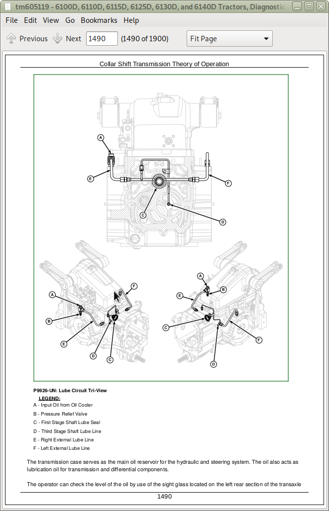
Group 15E: Collar Shift Transmission Diagnostics
Collar Shift Transmission Theory of Operation
Collar Shift Transmission Diagnostics
Group 15F: Top Shaft Synchronized (TSS) Transmission Diagnostics
TSS Transmission Theory of Operation
TSS Transmission Diagnostics
Group 20: Component Information
Power Train Component Information
Section 255: Drive Systems Diagnosis and Tests
Group 05: General Information
Drive Systems General Information
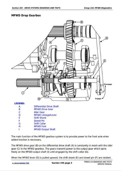
Group 15A: MFWD Diagnostics
MFWD Theory of Operation
Mechanical Front Wheel Drive Overall Diagnostics
Group 15B: Power Take Off (PTO) Diagnostics
PTO Theory of Operation
Rear PTO Diagnostics
Group 15C: Differential and Final Drive Diagnostics
Differential Theory of Operation
Differential Lock Theory of Operation
Final Drive Theory of Operation
Differential, Differential Lock, and Final Drive Diagnostics
Group 20: Component Information
Drive Systems Component Information
Section 260: Brake System Diagnosis and Test
Group 05: General Information
Brake System General Information
Brake Specifications
Group 10: Test Procedures and Adjustments
Adjust Brake Linkage and Pedal Travel
Group 15: Brake System Diagnostics
Brake System Theory of Operation
Brake System Diagnostics
Hydraulic Trailer Brake System Diagnostics
Group 20: Component Identification
Brake Component Identification and Location
Section 270: Hydraulic System Diagnosis and Tests
Group 05: General Information
Hydraulic System General Information
Hydraulic System Specifications
Hydraulic System Component Identification Legend
Group 10: Test Procedures and Adjustments
Heating Hydraulic Oil
Implement Pump Flow Test with SCV
Implement Pump Flow Test without SCV
Main Relief Pressure Test with SCV
Main Relief Pressure Test without SCV
Hydraulics - SCV Leakage Test
Hydraulics - Kickout Detent Pressure Test
Hydraulic Trailer Brake Valve Test
Group 15A: Basic Hydraulic System Overall Diagnostics
Hydraulic System Theory of Operation
Hydraulic System Schematics
Hydraulics - Hydraulic System Preliminary Check
Hydraulics - Hydraulic System Operational Check
Group 15B: Rockshaft System Diagnostics
Rockshaft Theory of Operation
Rockshaft Schematic
Rockshaft System Diagnostics
Group 15C: Rear Mount Selective Control Valve System Diagnostics
Hydraulics - Single and Dual Rear SCV Extend and Retract Operation
Hydraulics - Single and Dual Rear SCV Float Operation
Hydraulics - Single and Dual Rear SCV Neutral Operation
Hydraulics - Triple Rear SCV Extend and Retract Operation
Hydraulics - Triple Rear SCV Float Operation
Hydraulics - Triple Rear SCV Neutral Operation
Hydraulics - Triple Rear SCV Continuous Detent Operation
Hydraulics - Triple Rear SCV Kick-out Detent Operation
Hydraulics - Triple Rear SCV No Detent Operation
Hydraulics - Triple Rear SCV Priority Flow Control Valve Operation
Hydraulics - Quick Disconnect Coupler Operation
Rear Selective Control Valve Schematic
Hydraulics - Rear SCV System Diagnosis
Group 15D: Mid Mount Selective Control Valve System Diagnostics
Hydraulics - Dual Mid SCV Extend and Retract Operation
Hydraulics - Dual Mid SCV Float Operation
Hydraulics - Dual Mid SCV Neutral Operation
Hydraulics - Dual Mid SCV Regenerative Operation
Hydraulics - Triple Mid SCV Extend and Retract Operation
Hydraulics - Triple Mid SCV Neutral Operation
Hydraulics - Triple Mid SCV Float Operation
Hydraulics - Triple Mid SCV Flow Control Valve Operation
Hydraulics - Quick Disconnect Coupler Operation
Mid Mount Selective Control Valve Schematic
Hydraulics - Mid Stack SCV System Diagnosis
Group 15E: Hydraulic Trailer Brake Valve System Diagnostics
Hydraulics - Hydraulic Trailer Brake Valve Operation
Hydraulic Trailer Brake Valve Schematic
Hydraulics - Hydraulic Trailer Brake Valve System Diagnosis
Group 20: Component Information
Hydraulic Component Information
Section 280: Steering System Diagnosis and Tests
Group 05: General Information
Steering System General Information
Steering System Specifications
Steering System Component Identification Legend
Group 10: Test Procedures and Adjustments
Steering Valve Relief Test
Steering Valve Relief Test — With Anti-Cavitation and Surge Relief Valves
Steering Valve Leakage Test
Steering Cylinder Leakage Test
Steering Pump Flow Test
Group 15: Steering System Diagnostics
Steering System Theory of Operation
Steering System Schematic
Steering System Diagnostics
Group 20: Component Information
Component Information
Section 290: Operator Station Diagnosis and Tests
Group 05: General Information
General Information
Air Conditioning System Specifications
Group 10: Test and Adjustment Procedures
Air Conditioning System Static Pressure Test
Air Conditioning System Operating Pressure Test
Air Conditioning System Pressure and Leak Test
Air Conditioning System Temperature Drop Test
Adjust Heater Temperature Control Cable
Adjust A/C Temperature Control Switch
Group 15A: Air Conditioning and Heating Diagnostics
Operator Station - Air Conditioning System Operation
Condenser
Receiver-Drier
Expansion Valve
Thermostat Switch
Evaporator
High-Low Pressure Switch
Control Knobs for Heating and Cooling
Air Conditioning ON-OFF Switch and Temperature Control Knob
Heater Temperature Control Knob
Operator Station - Heating and Ventilation Operation
Air Conditioning and Heater Diagnostics
Group 15B: Seat Diagnostics
Air Seat Diagnostics
Group 20: Component Location
Air Conditioning and Heater Component Location
Section 299: Service Tools
Group 05: Dealer Fabricated Tools
DFRW126—Modified Tap Out Harness
DFRW130—Relay Circuit Test Lead
DFRW183—Coupler DR Assembly
DFRW213 — Hydraulic Trailer Brake Test / Bleed Assembly
Hydraulic Test Hoses
Dealer Fabricated Test Equipment
Group 10: Service Tools and Kits
38H1415 — Cap (-6 ORFS)
38H5003 — Straight Fitting (-8 (m) ORFS x M18 x 1.5 (m))
AR52361 — Quick Connect Coupler
D05330ST — Supplemental Accessory Kit
FKM10302 — Connector
FKM10303 — Connector
FKM10305 — Connector
JDG774 — Solenoid Test Harness
JDG1478—Digital Multimeter
JDG10466 — Flex Probe Kit
JT01767 — Supplemental Lawn and Grounds Care Products Hydraulic Fitting Kit
JT02046 — Charging Station
JT02050 — Recovery and Recycling Station
JT05412 — Industrial Universal Pressure Test Kit
JT05470 — Universal Pressure Test Kit
JT05473 — Gauge w/Quick Coupler, 35,000 kPa (350 bar) (5,000 psi)
JT05497 — Hose Assembly, 3048 mm (120 in.) Long
JT07119 — 5 ft. Test Hose
JT05685 — Battery Load Tester
JT05832 — Battery Load Tester
JT07115 — Master Hydraulic Test Kit
JT07115 SUP — Supplemental Master Hydraulic Test Kit
JT07148—Digital Hydraulic Tester
JT07253 — Infrared Temperature Gun
LVB24862—Wiring Harness
RE43774 — Diagnostic Receptacle (13/16-16 (f) ORFS)
RE60701 — Diagnostic Receptacle (-6 ORFS)
RE200690—Performance Monitor
John Deere Tractors 6100D, 6110D, 6115D, 6125D, 6130D, 6140D Diagnosis and Tests Service Technical Manual (TM605119)
![]()