
John Deere Tractors 6100D, 6110D, 6115D, 6125D, 6130D & 6140D Repair Service Manual (TM605019)
Complete Repair Service Technical Manual for John Deere Tractors 6100D, 6110D, 6115D, 6125D, 6130D, 6140D, with all the shop information to maintain, repair, service, and rebuild like professional mechanics.
John Deere Tractors 6100D, 6110D, 6115D, 6125D, 6130D and 6140D (November 2011) workshop technical manual (repair) includes:
* Numbered table of contents easy to use so that you can find the information you need fast.
* Detailed sub-steps expand on repair procedure information
* Numbered instructions guide you through every repair procedure step by step.
* Notes, cautions and warnings throughout each chapter pinpoint critical information.
* Bold figure number help you quickly match illustrations with instructions.
* Detailed illustrations, drawings and photos guide you through every procedure.
* Enlarged inset helps you identify and examine parts in detail.
tm605019 - 6100D, 6110D, 6115D, 6125D, 6130D, and 6140D Tractors, Repair Technical Manual (November 2011).pdf
tm605019 - 6100D, 6110D, 6115D, 6125D, 6130D, and 6140D Tractors, Repair Technical Manual (November 2011).epub
Total Pages: 937 pages
File Format: PDF/EPUB/MOBI/AZW (PC/Mac/Android/Kindle/iPhone/iPad; bookmarked, ToC, Searchable, Printable)
Language: English
MAIN SECTIONS
Foreword
General Information
Safety
Specifications
Fuel and Lubricants
Serial Number Locations
Engine Repair
Engine
Cooling System
Fuel and Air
Fuel System
Speed Control Linkage
Air Intake System
Electrical Repair
Battery, Starter and Alternator
Connectors
Wiring Harness Routing
Electrical System Components
Auxiliary Lighting Components
Fuses And Relays
Lighting
Power Train
Towing
Component Removal
PTO
Clutch
Separation
Steering and Brake Repair
Steering Repair
Front Axle-2WD
Front Axle-MFWD
Brake Repair
Hydraulic Repair
Hydraulic Pump and Oil Cooler
Rockshaft
Lubrication System
Selective Control Valve (SCV)
Mid-Mount Selective Control Valve (SCV)
Hydraulic Trailer Brake Valve
Miscellaneous Repair
Hood and Fenders
3-Point Hitch
Wheels
Front Support
Trailer Mounting and Swinging Drawbar
Open Operator Station Repair
Seat and Support
ROPS
Operator Platform
Cowl Repair
Cab-Operator Station Repair
Removal and Installation of Components
Selective Control Valve Cable Adjustment
Air Conditioning System
Heating System
Seat
SPECIAL TOOLS
DEALER-FABRICATED TOOLS
tm605019 - 6100D, 6110D, 6115D, 6125D, 6130D, and 6140D Tractors, Repair Technical Manual (November 2011)
Table of Contents
Foreword
Section 10: General Information
Group 05: Safety
Recognize Safety Information
Understand Signal Words
Prevent Machine Runaway
Handle Fluids Safely—Avoid Fires
Prevent Battery Explosions
Prepare for Emergencies
Prevent Acid Burns
Handle Agricultural Chemicals Safely
Avoid High-Pressure Fluids
Park Machine Safely
Support Machine Properly
Wear Protective Clothing
Work in Clean Area
Service Machines Safely
Work In Ventilated Area
Illuminate Work Area Safely
Replace Safety Signs
Use Proper Lifting Equipment
Construct Dealer-Made Tools Safely
Remove Paint Before Welding or Heating
Avoid Heating Near Pressurized Fluid Lines
Keep ROPS Installed Properly
Service Tires Safely
Avoid Harmful Asbestos Dust
Practice Safe Maintenance
Use Proper Tools
Dispose of Waste Properly
Service Cooling System Safely
Servicing Electronic Control Units
Welding Near Electronic Control Units
Keep Electronic Control Unit Connectors Clean
Live With Safety
Group 10: Specifications
General Specifications
Overall Dimensions and Weights
Turning Radius—2WD Axle
Turning Radius—MFWD Axle
Ground Speeds—Collar Shift (CST) or Top Shaft Synchronized (TSS) Transmission
Ground Speeds—PowrReverser™ Transmission (PRT)
Metric Bolt and Screw Torque Values
Unified Inch Bolt and Screw Torque Values
How To Dispense/Apply/Assemble Gasket Sealants
Face Seal Fittings Assembly and Installation—All Pressure Applications
Metric Face Seal Fitting Torque Chart—Standard Pressure Applications
SAE Face Seal Fitting Torque Chart—Standard Pressure Applications
Metric Face Seal Fitting Torque Chart—High Pressure Applications
SAE Face Seal Fitting Torque Chart—High Pressure Applications
Prevent Hydraulic System Contamination
Check Oil Lines and Fittings
Group 15: Fuel and Lubricants
Diesel Fuel
Storing Fuel
Testing Diesel Fuel
Heavy Duty Diesel Engine Coolant
Diesel Engine Oil
Transmission and Hydraulic Oil
Fill The Transmission With Oil
Check And Service Transmission Regularly
Transaxle—Assembly Lubrication
Cold Weather Operation
MFWD Axle and Wheel Hub Oil
Lubricant Storage
Alternative and Synthetic Lubricants
Grease (Specific Application)
Grease
Group 20: Serial Number Locations
Serial Numbers
Product Identification Number Location
Engine Serial Number Location
Fuel Injection Pump Serial Number Location
Transaxle Serial Number Location
MFWD Serial Number Location (If Equipped)
Cab Serial Number Location
Section 20: Engine Repair
Group 05: Engine
Essential or Recommended Tools
Other Material
Specifications
John Deere Engine Repair—Use CTM
Remove and Install Engine
Remove and Install Engine Oil Pan
Remove and Install Rocker Arm Cover
Access To Rear Crankshaft Seal
Access To Front Crankshaft Seal
Access To Front Timing Cover
Group 10: Cooling System
Other Material
Specifications
Engine Water Pump Repair—Use CTM
Replace and Inspect Alternator/Fan Belt
Remove, Inspect and Install Radiator
Remove and Install Cooling Package
Remove Water Pump
Install Water Pump
Remove and Install Thermostat—Use CTM
Pressure Test Cooling System and Radiator Cap
Section 30: Fuel and Air
Group 05: Fuel System
Injection Pump, Nozzles and Governor Repair—Use CTM
Remove and Install Fuel Tank
Replace Fuel Level Sender
Replace Final Fuel Filter and Primary Fuel Filter/Water Separator
Remove and Install Fuel Supply Pump
Group 10: Speed Control Linkage
Specifications
Inspect and Repair Speed Control Linkage—Mechanical
Remove and Install Throttle Handle Assembly
Remove and Install Throttle Handle Potentiometer
Remove and Install Throttle Pedal Assembly
Remove and Install Throttle Pedal Potentiometer
Throttle Lever Friction Adjustment
Adjust Throttle Linkage
Group 15: Air Intake System
Specifications
Replace Air Cleaner Elements/Housing
Inspect and Service Air Intake System
Remove Turbocharger
Install Turbocharger
Turbocharger Break-In
Section 40: Electrical Repair
Group 05: Battery, Starter and Alternator
Specifications
Prevent Battery Explosions
Handling Batteries Safely
Prevent Damage to Electrical Systems
Connecting Booster Battery
Charging Batteries
Connecting Battery Cables
Remove and Install Battery
Remove and Install Starter
Starter Repair—Use CTM
Replace Alternator
Group 10: Connectors
Essential or Recommended Tools
Other Material
Use Electrical Insulating Compound
Using High-Pressure Washers
Repair AMP Injection Pump Connector
Remove Connector Body from Blade Terminals
Repair CINCH Connectors
Repair 32 and 48 Way CINCH Connectors
Repair CPC Blade Type Connectors
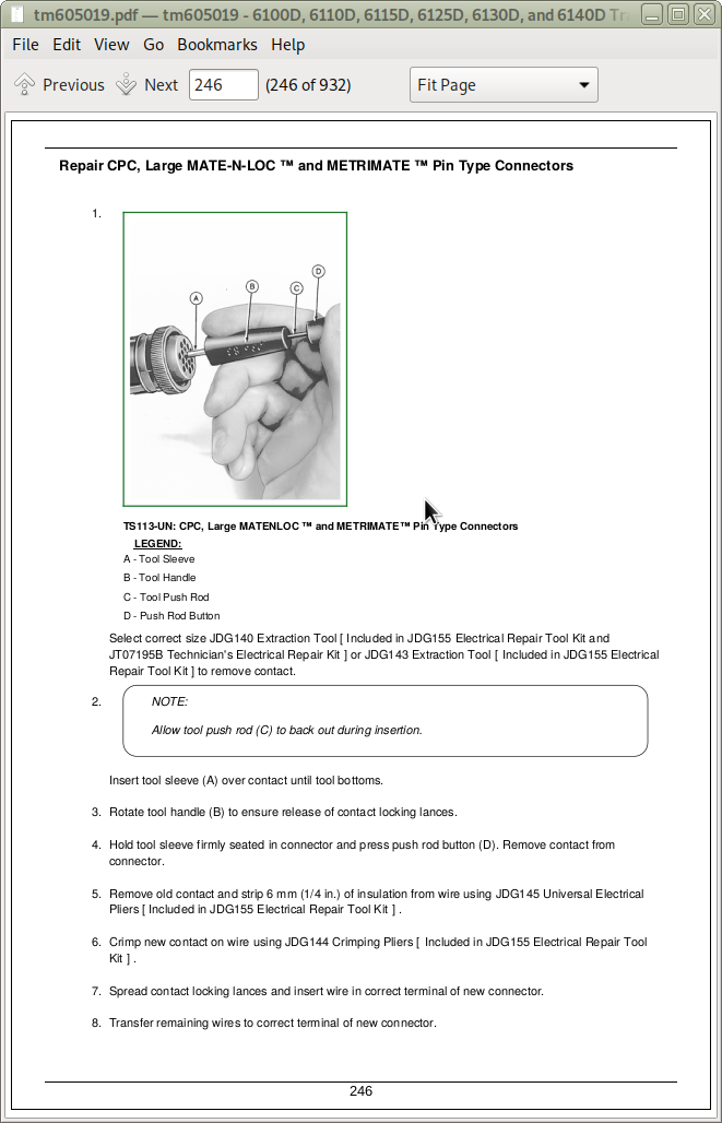
Repair CPC, Large MATE-N-LOC MATE-N-LOC is a trademark of AMP Incorporated and METRIMATE METRIMATE is a trademark of AMP Incorporated Pin Type Connectors
Repair DEUTSCH Connectors
Repair ITT Connector
Repair Small MATE-N-LOC Socket Connector
Repair Small MATE-N-LOC Pin Connector
Repair (Pull Type) METRI-PACK METRI-PACK is a trademark of Delphi Packard Electric Systems Connectors
Repair (Push Type) METRI-PACK Connectors
Repair Molex Connector
Repair SUMITOMO™ Connectors
Repair Weather Pack Weather Pack is a trademark of Packard Electric Connector
Repair YAZAKI™ Connectors
Group 15: Wiring Harness Routing
Tractor Wiring Harness Replacement
Engine Harness—Tier 0/Tier 1
Engine Harness—Tier 3
Transmission Harness
Chassis Harness—Cab Tractors
Front Console Harness—Cab Tractors
Cab Roof Harness
Chassis/Front Console Harness—OOS Tractors
Group 20: Electrical System Components
Service Equipment and Tools
Other Material
Specifications
Replace Air Filter Restriction Switch
Replace Coolant Temperature Sensor
Replace Engine Speed Sensor
Replace Engine Oil Pressure Sensor
Remove and Install Instrument Panel
Replace Key Switch
Remove and Replace Light Switch
Replace Turn Signal Switch
Remove and Replace EH Directional Reverser Lever
Remove and Install Acceleration Potentiometer (Shuttle Control)
Replace Rear PTO Switch
Replace Neutral Start Switch (If Equipped)
Replace Horn Switch
Replace Horn
Replace Audible Alarm
Replace Starter Relay
Manifold Heater and Relay—Exploded View (If Equipped)
Replace Speakers
Replace Antenna
Replace Wiper Control Switch
Remove And Install Wiper Motor
Replace Blower Control Switch
Replace A/C On/Off Switch
Replace A/C Temperature Control Switch
Replace Blower Motor Resistor
Replace Dome Light
Replace Door Switch
Remove and Install ECU/PTR Controllers—OOS
Remove and Install ECU/PTR Controllers—Cab
Group 25: Auxiliary Lighting Components
Replace Seven Terminal Outlet Socket (If Equipped)
Replace Seven Terminal Outlet Socket (European) (If Equipped)
Group 30: Fuses And Relays
Access Fuses and Relays
Load Center Fuses and Relays-OOS (6100D/6110D/6125D with Dry Clutch and without Handbrake)
Load Center Fuses and Relays-OOS (6110D/6125D with Wet Clutch and without Handbrake)
Load Center Fuses and Relays-OOS (6100D/6110D/6125D with PowrReverser and without Handbrake)
Load Center Fuses and Relays-OOS (6115D/6130D/6140D without PowrReverser and without Handbrake)
Load Center Fuses and Relays-OOS (6115D/6130D/6140D with PowrReverser and without Handbrake)
Load Center Fuses and Relays-OOS—Behind Instrument Panel
Load Center Fuses and Relays-OOS—Behind Panel at Left Rear Corner of Operators Station
Load Center Fuses and Relays—Cab (6100D/6110D/6125D with Dry Clutch and without Handbrake)
Load Center Fuses and Relays—Cab (6110D/6125D with Wet Clutch and without Handbrake)
Load Center Fuses and Relays—Cab (6100D/6110D/6125D with PowrReverser™ and without Handbrake)
Load Center Fuses and Relays—Cab (6115D/6130D/6140D without PowrReverser and without Handbrake)
Load Center Fuses and Relays—Cab (6115D/6130D/6140D with PowrReverser and without Handbrake)
Load Center Fuses and Relays—Cab—Behind Instrument Panel
Load Center Fuses and Relays—OOS (6115D/6130D with Dry Clutch and with Handbrake)
Load Center Fuses and Relays-OOS (6115D/6130D with Wet Clutch and with Handbrake)
Load Center Fuses and Relays-OOS (6115D/6130D with PowerReverser and with Handbrake)
Load Center Fuses and Relays-Cab (6115D/6130D with Dry clutch and with Handbrake)
Load Center Fuses and Relays-Cab (6115D/6130D with Wet clutch and with Handbrake)
Load Center Fuses and Relays-Cab (6115D/6130D with PowerReverser and with Handbrake)
Load Center Fuses and Relays—Cab (European)
Fusible Link Location
Diode Location - Console
Group 35: Lighting
Safety Rules When Replacing Halogen Bulbs
Replace Headlight Bulbs
Replace Auxiliary Field Light Bulbs - OOS
Replace Warning Light Bulb - Cab
Replace Tail Light Bulb - Cab
Replace Warning/Tail Light Bulbs - OOS
Replace Hazard Light Bulb - OOS
Section 50: Power Train
Group 00: Towing
Towing Tractor
Adjust Range Shift Lever and Tow Lock
Group 05: Component Removal
Essential or Recommended Tools
Other Material
Specifications
Transaxle Separation and Repair—Use CTM
Remove and Install Rear PTO Drive Shaft Assembly
Remove and Install Final Drive Assembly
Remove and Install Clutch
Remove, Inspect and Install MFWD Drive Shaft
Remove and Install MFWD Drop Gearbox
Group 10: PTO
PTO Housing Repair—Use CTM
Remove, Inspect and Install PTO Lever and Linkage
Determine PTO Clutch Linkage Adjustment Procedure
Adjust PTO Clutch Linkage—(OOS)
Adjust PTO Clutch Cable—(Cab Tractors)
Group 15: Clutch
Essential or Recommended Tools
Other Material
Specifications
Separate and Install Engine-to-Clutch Housing
Remove and Install Clutch Linkage (Collar Shift Transmission)
Remove and Install Clutch Linkage (Synchronized Transmission)
Remove and Install Clutch Pedal Position Sensor—Wet Clutch
Adjust Interlock Cable
Adjust Clutch Pedal and Linkage
Group 25: Separation
Park Tractor
Remove Battery
Relieve Hydraulic Pressure
Drain Hydraulic Oil
Remove Fuel Tank
Remove Operator Cab
Remove Operator Station
Remove Complete Transmission Harness Cab / OOS
Remove MFWD Drive Shaft
Split Tractor
Section 60: Steering and Brake Repair
Group 05: Steering Repair
Specifications
Remove and Install Steering Wheel
Remove and Install Steering Column
Remove and Install Steering Valve (Open Operator Station)
Remove and Install Steering Valve (Cab Tractors)
Start-Up Procedure After Hydraulic System Repairs
Group 10: Front Axle—2WD
Essential or Recommended Tools
Other Material
Specifications
Remove Front Axle—2WD
Install Front Axle—2WD
Disassemble Front Axle—2WD
Assemble Front Axle—2WD
Adjust Knuckle and Spindle Assembly Axial Play—2WD
Assemble Wheel Hub—2WD
Adjust Wheel Bearings—2WD
Remove and Install Axle Pivot Pins/Bushings—2WD
Install Tie Rod—2WD
Check And Adjust Toe-In—2WD
Remove and Install Steering Cylinder—2WD
Disassemble, Inspect and Assemble Steering Cylinder—2WD
Group 15: Front Axle—MFWD
Essential or Recommended Tools
Specifications
Remove, Inspect and Install Tie Rod Assembly—MFWD
Check And Adjust Toe-In—MFWD
Remove and Install Steering Cylinder—MFWD
Disassemble, Inspect and Assemble Steering Cylinder—MFWD
Remove Front Axle—MFWD
Install Front Axle—MFWD
Group 20: Brake Repair
Specifications
Remove and Replace Brake Pedals and Linkage
Adjust Brake Linkage and Pedal Travel
Checking and Adjusting Hand Brake Lever
Section 70: Hydraulic Repair
Group 05: Hydraulic Pump and Oil Cooler
Other Material
Specifications
Service Parts Kits
Remove and Install Hydraulic Oil Cooler
Remove and Install Hydraulic Pump
Disassemble and Assemble Hydraulic Pump
Start-Up Procedure After Hydraulic System Repairs
Group 10: Rockshaft
Essential or Recommended Tools
Other Material
Specifications
Service Parts Kit
Remove, Inspect and Install Hitch Rate-of-Drop Valve
Remove and Install Rockshaft Control Valve
Disassemble, Inspect and Assemble Rockshaft Control Valve
Remove and Install Rockshaft Housing
Disassemble and Assemble Rockshaft
Remove and Install Rockshaft Cylinder
Remove, Inspect and Replace Rockshaft Internal Linkage
Disassemble and Assemble Rockshaft Control Linkage and Levers
Rockshaft Internal Linkage
Adjust Rockshaft Internal Linkage (Lift Arm Raise Limit)
Adjust Rockshaft Control Lever (OOS Tractors)
Adjust Rockshaft Control Lever (Cab Tractors)
Adjust Load Sense Linkage (OOS Tractors)
Adjust Load Sense Linkage (Cab Tractors)
Group 15: Lubrication System
Specifications
Remove and Install Lubrication System Relief Valve
Group 20: Selective Control Valve (SCV)
Other Material
Specifications
Service Parts Kits
Remove and Install Selective Control Valve
Disassemble, Inspect and Assemble Selective Control Valve
Rear Triple Deluxe SCV Kick-Out Relief Valve Adjustment
Group 25: Mid-Mount Selective Control Valve (SCV)
Other Material
Specifications
Remove and Install Mid-Mount Selective Control Valve
Disassemble, Inspect, and Assemble Dual Mid-Mount Control Valve
Inspect and Repair Joystick and Linkage
Adjust Mid-Mount Control Valve Cable
Group 30: Hydraulic Trailer Brake Valve
Specifications
Remove, Inspect and Install Hydraulic Trailer Brake Valve
Hydraulic Trailer Brake Valve Control Cable Adjustment
Section 80: Miscellaneous Repair
Group 05: Hood and Fenders
Specifications
Remove and Install Front Fender
Remove and Install Fender Extensions—OOS
Remove and Install Fenders—Cab Tractors
Remove and Install Hood
Group 10: 3-Point Hitch
Essential or Recommended Tools
Other Material
Specifications
Inspect and Repair Stabilizer Chains
Inspect and Repair Standard Lift Link
Inspect and Repair Adjustable Lift Link
Inspect and Repair Center Link
Remove and Install Draft Link Pivot Shaft
Remove and Install Drawbar
Group 15: Wheels
Essential or Recommended Tools
Specifications
Remove and Install Front and Rear Wheels
Remove and Install Wheel Rim
Rear Ballast
Group 20: Front Support
Essential or Recommended Tools
Specifications
Remove, Inspect and Install Front Support
Group 25: Trailer Mounting and Swinging Drawbar
Guide Rails for Height-Adjustable Trailer Hitch
Checking the Manually-Operated Hitch (EEC Type) for Wear
Checking the Manually-Operated Hitch (CUNA Type) for Wear
Checking the Tow-Hook for Wear
Checking the Hitch Ball for Wear
Checking the Swinging Drawbar for Wear
Section 90: Open Operator Station Repair
Group 05: Seat and Support
Specifications
Remove and Install Seat and Support
Group 10: ROPS
Specifications
Check ROPS
Disassemble ROPS Canopy
Remove and Install ROPS
Group 15: Operator Platform
Other Material
Specifications
Remove Operator Station
Install Operator Station
Group 20: Cowl Repair
Remove and Install Cowl
Section 95: Cab—Operator Station Repair
Group 00: Removal and Installation of Components
Service Equipment and Tools
Essential Tools
Specifications
Remove, Inspect, and Install Cab Interior Recirculating Air Filters
Remove, Inspect, and Install Exterior Cab Intake Air Filters
Remove and Install Headliner
Remove and Install Fender Console
Remove and Install Cowl
Remove and Install Windshield
Remove and Install Rear Window
Remove and Install Front Lower Windows
Remove and Install Rear Lower Window
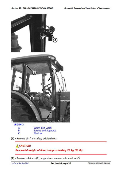
Remove and Install Side Windows
Remove and Install Cab Doors
Remove and Install Cab Roof
Remove and Install Safety Exit Door
Installing Door Lock
Remove Operator Cab
Install Operator Cab
Group 05: Selective Control Valve Cable Adjustment
Specifications
Remove and Install Selective Control Valve Cable (Cab Tractors)
Group 10: Air Conditioning System
Essential Tools
Service Equipment and Tools
Other Material
Specifications
Service Parts Kits
Recover/Recycle Air Conditioning Refrigerant
Replace Air Conditioning Receiver-Dryer
Remove, Inspect, and Install Air Conditioning Condenser
Remove, Inspect, and Install Air Conditioning Compressor
Test Volumetric Efficiency of Compressor
Test Compressor Shaft Seal Leakage
Disassemble and Assemble Compressor Clutch
Disassemble, Inspect, and Assemble Compressor
Check Compressor Clutch Hub Clearance
Inspect Compressor Manifold
Remove and Install Compressor Relief Valve
Remove and Install the Evaporator and Expansion Valve
Arrangement of Condensation Water Drain Hoses
Remove and Install A/C Thermostat Switch
Adjust Thermostat Switch Bowden Cable
Remove and Install the High/Low Pressure Switch
Expansion Valve Bench Test
Refrigerant Oil Information
Check Compressor Oil Charge
Determine Correct Refrigerant Oil Charge
Add Refrigerant Oil to System
System Information
Flush Air Conditioning System
Evacuate Air Conditioning System
Charge Air Conditioning System
Group 15: Heating System
Remove and Install Radiator
Remove and Install Fan Motors
Remove and Install Fan Motor Resistors
Remove and Install Heater Valve
Adjust Heater Valve Bowden Cable
Group 20: Seat
Remove and Install Seat and Support
Section 99: SPECIAL TOOLS
Group 05: DEALER-FABRICATED TOOLS
DFRW20—Compressor Holding Fixture
Short Adapter
Group : Service Tools
JT02098 — Air Conditioning Flushing Kit
JT07120 — Load Valve Assembly
JT03105 — Connector (1/2 (m) NPT X 1/4 (f) NPT)
JT03261 — Coupler (1/4 (m) NPT)
JT05497 — Hose Assembly, 3048 mm (120 in.) Long
JT07117 — Three-Gauge Manifold
JT03348 — Tee Fitting (1/2 (f) NPT x 1/2 (f) NPT x 1/2 (f) NPT)
R36659 — Hydraulic Jumper Hose (3 ft)
John Deere Tractors 6100D, 6110D, 6115D, 6125D, 6130D & 6140D Repair Service Manual (TM605019)
![]()