
John Deere Tractors 6100D, 6110D, 6115D, 6125D & 6130D Repair Service Manual (TM608819)
Complete Repair Service Technical Manual for John Deere Tractors 6100D, 6110D, 6115D, 6125D, 6130D (S.N. 060000-) Tier 3, with workshop information to maintain, repair, and service like professional mechanics.
John Deere 2WD or MFWD Tractors 6100D, 6110D, 6115D, 6125D & 6130D (Tier 0 - Tier III-Stage IIIA) workshop technical manual (repair) includes:
* Numbered table of contents easy to use so that you can find the information you need fast.
* Detailed sub-steps expand on repair procedure information
* Numbered instructions guide you through every repair procedure step by step.
* Notes, cautions and warnings throughout each chapter pinpoint critical information.
* Bold figure number help you quickly match illustrations with instructions.
* Detailed illustrations, drawings and photos guide you through every procedure.
* Enlarged inset helps you identify and examine parts in detail.
tm608819 - 6100D, 6110D, 6115D, 6125D and 6130D (Tier 0-Tier 3_Stage IIIA) Tractors Repair Technical Manual (60000—), Nov. 2014—.pdf
tm608819 - 6100D, 6110D, 6115D, 6125D and 6130D (Tier 0-Tier 3_Stage IIIA) Tractors Repair Technical Manual (60000—), Nov. 2014—.epub
Total Pages: 751 pages
File Format: PDF/EPUB/MOBI/AZW (PC/Mac/Android/Kindle/iPhone/iPad; bookmarked, ToC, Searchable, Printable)
Language: English
MAIN SECTIONS
Foreword
General Information
Safety
General Information
Fuels, Lubricants and Coolant
Engine Repair
Engine
Cooling System
Fuel, Air Intake, and Exhaust Systems
Fuel System
Air Intake System
Exhaust System
Electrical System
Connectors
Charging Circuit
Starting Circuit
Electrical System Components
Drive Systems and Transmission
Towing
Component Removal
PTO
Clutch
Steering and Brakes
Steering Repair
Front Axle-2WD
Front Axle-MFWD
Brake Repair
Hydraulics
Hydraulic Pump
Hydraulic Oil Cooler
Hitch Valve
Hydraulic Rear Selective Control Valve
Hydraulic Mid-Mount Selective Control Valve
Hydraulic Trailer Brake Valve
Miscellaneous
Hood and Fenders
Hitch and Drawbar
Front Support
Open Operator Station Repair
Seat and Support
ROPS
Operator Platform
Cowl Repair
Cab-Operator Station Repair
Removal and Installation of Components
Air Conditioning System
Heating System
Seat
Special Tools
Dealer Fabricated Tools
Service Tools
tm608819 - 6100D, 6110D, 6115D, 6125D and 6130D(Tier 0 —Tier 3/Stage IIIA) Tractors Repair Technical Manual(60000—), 11/2014—
Table of Contents
Foreword
Section 10: General Information
Group 05: Safety
Recognize Safety Information
Understand Signal Words
Follow Safety Instructions
Wear Protective Clothing
Service Machines Safely
Stay Clear of Rotating Drivelines
Handle Fluids Safely—Avoid Fires
Prevent Battery Explosions
Prepare for Emergencies
Remove Paint Before Welding or Heating
Avoid Heating Near Pressurized Fluid Lines
Handle Starting Fluid Safely
Avoid Hot Exhaust
Clean Exhaust Filter Safely
Prevent Acid Burns
Handle Agricultural Chemicals Safely
Clean Vehicle of Hazardous Pesticides
Handling Batteries Safely
Avoid Harmful Asbestos Dust
Dispose of Waste Properly
Avoid High-Pressure Fluids
Wait Before Opening High-Pressure Fuel System
Protect Against High Pressure Spray
Service Cooling System Safely
Prevent Machine Runaway
Keep ROPS Installed Properly
Avoid Backover Accidents
Park Machine Safely
Support Machine Properly
Work in Clean Area
Work In Ventilated Area
Illuminate Work Area Safely
Use Proper Lifting Equipment
Service Tires Safely
Service Front-Wheel Drive Tractor Safely
Use Steps and Handholds Correctly
Transport Tractor Safely
Practice Safe Maintenance
Use Proper Tools
Construct Dealer-Made Tools Safely
Replace Safety Signs
Install All Guards
Live With Safety
Group 10: General Information
Sealants and Adhesives Cross-Reference Chart
Metric Bolt and Screw Torque Values
Unified Inch Bolt and Screw Torque Values
Face Seal Fittings Assembly and Installation—All Pressure Applications
Metric Face Seal And O-Ring Stud End Fitting Torque Chart—Standard Pressures
Metric Face Seal and O-Ring Stud End Fitting Torque Chart—High Pressure Applications
SAE Face Seal and O-Ring Stud End Fitting Torque Chart—Standard Pressures
SAE Face Seal and O-Ring Stud End Fitting Torque Chart—High Pressure Applications
Four Bolt Flange Fittings Assembly and Installation—All Pressure Applications
SAE Four Bolt Flange Cap Screw Torque Values—Standard Pressure Applications
SAE Four Bolt Flange Cap Screw Torque Values—High Pressure Applications
External Hexagon Port Plug Torque Chart
Prevent Hydraulic System Contamination
Check Oil Lines and Fittings
Basic Electrical Component Handling / Precautions For Vehicles Equipped With Computer Controlled Systems
Identify Zinc-Flake Coated Fasteners
Use Torque Wrench Adapter
Group 15: Fuels, Lubricants and Coolant
Handle Fuel Safely—Avoid Fires
Handle Fluids Safely—Avoid Fires
Cold Weather Operation
Hot Weather Operation
Diesel Fuel
Handling and Storing Diesel Fuel
Lubricity of Diesel Fuel
Testing Diesel Fuel
BioDiesel Fuel
Fill Fuel Tank
Diesel Engine Break-In Oil
Diesel Engine Oil — Tier 2 and Stage II
Extended Diesel Engine Oil Service Intervals — Non-Emissions Certified and Certified Tier 1 and Stage I
Oil Filters
Diesel Engine Coolant (engine with wet sleeve cylinder liners)
Operating in Warm Temperature Climates
Liquid Coolant Conditioner
Additional Information About Diesel Engine Coolants and John Deere LIQUID COOLANT CONDITIONER
Testing Diesel Engine Coolant
Transmission and Hydraulic Oil
Use Correct Transmission/Hydraulic Filter Element
MFWD Axle and Wheel Hub Oil
Grease
Mixing of Lubricants
Alternative and Synthetic Lubricants
Lubricant Storage
Section 20: Engine Repair
Group 05: Engine
Essential, Recommended, and Fabricated Tools
Other Material
Specifications
Remove and Install Engine
Remove and Install Rocker Arm Cover
Repair Engine—Use CTM
Group 10: Cooling System
Essential, Recommended, and Fabricated Tools
Specifications
Test Radiator and Deaeration Tank
Test Radiator Cap
Remove and Install Radiator
Remove and Install Cooling Package
Remove and Install Deaeration Tank
Cooling System Repair—Use CTM
Section 30: Fuel, Air Intake, and Exhaust Systems
Group 05: Fuel System
Specifications
Remove and Install Fuel Tank
Replace Fuel Level Sender
Remove and Install Fuel Supply Pump
Remove, Inspect and Install Fuel Cooler
Replace Fuel Strainer and In-Line Check Valve
Group 10: Air Intake System
Specifications
Turbocharger Repair
Remove and Install Air Cleaner—Axial Type
Remove, Inspect and Install Charge Air Cooler (CAC)
Air Intake Pipe Connections
Group 15: Exhaust System
Other Material
Specifications
Service Exhaust System
Section 40: Electrical System
Group 05: Connectors
Essential, Recommended, and Fabricated Tools
Other Material
Use Electrical Insulating Compound
Using High-Pressure Washers
Repair AMP™ Connector
Repair AMPSEAL 16™ Connectors
CAN Controlled SCV Connectors
Remove Connector Body from Blade Terminals
CINCH™ Control Unit Connectors
Exploded View—CINCH™ FlexBox Connectors
CINCH™ FlexBox Connectors
Repair CPC™ Blade Type Connectors
Repair CPC™, Large Mate-N-Loc™, and Metrimate™ Pin Type Connectors
Repair DEUTSCH™ Connectors
Repair DEUTSCH™ Implement Connectors
Repair ITT Connector
Repair Small Mate-N-Loc™ Socket Connector
Repair Small Mate-N-Loc™ Pin Connector
Repair (Pull Type) Metri-Pack™ Connectors
Repair (Push Type) Metri-Pack™ Connectors
Repair Molex™ Control Unit Connectors
Repair Molex™ Connector
Repair SUMITOMO™ Connectors
Repair Tyco™ Fuel Injector Connector
Repair WEATHER PACK™ Connector
Repair YAZAKI™ Connectors
Group 10: Charging Circuit
Specifications
Repair Alternator—Use CTM
Remove and Install Alternator
Group 15: Starting Circuit
Specifications
Repair Starter—Use CTM
Remove and Install Starter Motor
Group 20: Electrical System Components
General Repair Procedures
Repair Engine Electrical System Components—Use CTM
Remove and Install Instrument Panel
Replace Key Switch
Remove and Replace Light Switch
Replace Turn Signal Switch
Remove and Replace EH Directional Reverser Lever
Remove and Install Acceleration Potentiometer (Shuttle Control)
Replace Horn Switch
Replace Starter Relay
Replace Speakers
Replace Antenna
Replace Wiper Control Switch
Remove And Install Wiper Motor
Replace Blower Control Switch
Replace Air Conditioning On-Off Switch
Replace Air Conditioning Temperature Control Switch
Replace Blower Motor Resistor
Replace A/C High/Low Pressure Switch
Replace Dome Light
Replace Door Switch
Replace EH PTO Switch
Replace Electro-Hydraulic Control (EHC) Unit—OOS
Replace Electro-Hydraulic Control (EHC) Unit—Cab
Replace Engine Control Unit (ECU)
Section 50: Drive Systems and Transmission
Group 00: Towing
Towing Tractor
Group 05: Component Removal
Essential or Recommended Tools
Other Material
Specifications
Transaxle Separation and Repair
Transmission Component Identification
Transmission Drain Plug Locations
Remove and Install Rear PTO Drive Shaft Assembly
Remove and Install Final Drive Assembly
Remove, Inspect and Install MFWD Drive Shaft
Remove and Install MFWD Drop Gearbox
Split Tractor
Group 10: PTO
PTO Repair—Use CTM
Group 15: Clutch
Other Material
Specifications
Remove and Install Clutch Linkage
Remove and Install Clutch Pedal Position Sensor
Adjust Interlock Cable
Adjust Clutch Pedal and Linkage
Section 60: Steering and Brakes
Group 05: Steering Repair
Specifications
Remove and Install Steering Wheel
Remove and Install Tilt/Telescoping Steering Column
Remove and Install Steering Valve (Open Operator Station)
Remove and Install Steering Valve (Cab Tractors)
Start-Up Procedure After Hydraulic System Repairs
Group 10: Front Axle—2WD
Essential, Recommended, and Fabricated Tools
Other Material
Specifications
Remove Front Axle—2WD
Install Front Axle—2WD
Disassemble Front Axle—2WD
Assemble Front Axle—2WD
Adjust Knuckle and Spindle Assembly Axial Play—2WD
Assemble Wheel Hub—2WD
Adjust Wheel Bearings—2WD
Remove and Install Axle Pivot Pins/Bushings—2WD
Install Tie Rod—2WD
Check And Adjust Toe-In—2WD
Remove and Install Steering Cylinder—2WD
Disassemble, Inspect and Assemble Steering Cylinder—2WD
Group 15: Front Axle—MFWD
Essential, Recommended, and Fabricated Tools
Specifications
Remove, Inspect and Install Tie Rod Assembly—MFWD
Check And Adjust Toe-In—MFWD
Remove and Install Steering Cylinder—MFWD
Disassemble, Inspect and Assemble Steering Cylinder—MFWD
Remove Front Axle—MFWD
Install Front Axle—MFWD
Group 20: Brake Repair
Specifications
Remove and Replace Brake Pedals and Linkage
Adjust Brake Linkage and Pedal Travel
Checking and Adjusting Hand Brake Lever
Section 70: Hydraulics
Group 05: Hydraulic Pump
Essential, Recommended, and Fabricated Tools
Specifications
Remove and Install Hydraulic Pumps
Disassemble, Inspect and Assemble Hydraulic Pumps
Start-Up Procedure After Hydraulic System Repairs
Group 10: Hydraulic Oil Cooler
Remove and Install Hydraulic Oil Cooler
Group 15: Hitch Valve
Other Material
Specifications
Disassemble and Assemble Control Linkages and Levers—(OOS)
Disassemble and Assemble Control Cables and Levers—(Cab)
Inspect and Repair Hitch Control Box
Remove and Install Hitch Valve
Replace Main Relief Valve
Replace Shock Relief Valve
Remove, Inspect and Install Rate-of-Drop Valve
Remove, Inspect and Install Load Sense Relief Valve
Inspect and Repair Draft Sensing Assembly
Install Draft Link Shaft
Remove, Inspect and Install Lift Arms
Remove, Inspect and Install Lift Cylinders
Draft Control and Position Control Linkage Adjustment—OOS
Draft Control and Position Control Cable Adjustment—Cab
3-Point Hitch Position Feedback Linkage Adjustment
Draft Sensing Feedback Cable Adjustment
Group 20: Hydraulic Rear Selective Control Valve
Essential, Recommended, and Fabricated Tools
Other Material
Specifications
Inspect and Repair SCV Levers and Linkage (Cab)
Remove and Install Rear Selective Control Valve (SCV)
Disassemble, Inspect and Assemble Single Rear Selective Control Valve (SCV)
Disassemble, Inspect and Assemble Dual Rear Selective Control Valve (SCV)
Triple Rear Selective Control Valve (SCV) Sectional View
Disassemble, Inspect and Assemble Triple Rear Selective Control Valve (SCV)
Rear SCV Control Cable Adjustment
Rear Triple Deluxe SCV Kick-Out Relief Valve Adjustment
Group 25: Hydraulic Mid-Mount Selective Control Valve
Other Material
Specifications
Inspect and Repair Joystick and Linkage
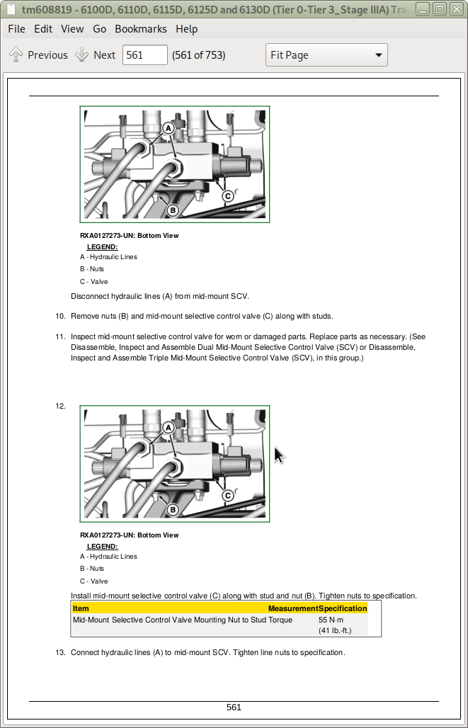
Remove and Install Mid-Mount Selective Control Valve (SCV)
Disassemble, Inspect and Assemble Dual Mid-Mount Selective Control Valve (SCV)
Disassemble, Inspect and Assemble Triple Mid-Mount Selective Control Valve (SCV)
Group 30: Hydraulic Trailer Brake Valve
Specifications
Remove, Inspect and Install Hydraulic Trailer Brake (HTB) Valve
Hydraulic Trailer Brake Valve Control Cable Adjustment
Section 80: Miscellaneous
Group 05: Hood and Fenders
Remove and Install Front Fender
Remove and Install Fender Extensions—OOS
Remove and Install Fenders—Cab Tractors
Remove and Install Hood
Group 10: Hitch and Drawbar
Specifications
Remove and Install Drawbar and Support
Inspect and Repair Stabilizer Chains
Remove and Install Trailer Hitch
Checking the Manually-Operated Hitch (EEC Type) for Wear
Checking the Manually-Operated Hitch (CUNA Type) for Wear
Group 15: Front Support
Essential, Recommended, and Fabricated Tools
Specifications
Remove, Inspect, and Install Front Support
Section 90: Open Operator Station Repair
Group 05: Seat and Support
Remove and Install Seat and Support
Group 10: ROPS
Specifications
Check ROPS
Remove and Install ROPS
Group 15: Operator Platform
Other Material
Specifications
Remove Operator Station
Install Operator Station
Group 20: Cowl Repair
Remove and Install Cowl
Section 95: Cab—Operator Station Repair
Group 00: Removal and Installation of Components
Essential, Recommended, and Fabricated Tools
Specifications
Remove, Inspect, and Install Cab Interior Recirculating Air Filters
Remove, Inspect, and Install Exterior Cab Intake Air Filters
Remove and Install Headliner
Remove and Install Right-Side Control Console
Remove and Install Left-Side Control Console
Remove and Install Cowl
Remove and Install Windshield
Remove and Install Rear Window
Remove and Install Front Lower Windows
Remove and Install Rear Lower Window
Remove and Install Side Windows
Remove and Install Cab Doors
Remove and Install Cab Roof
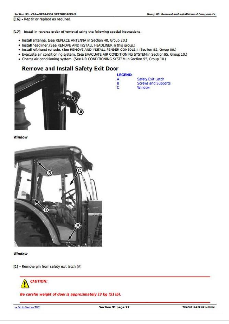
Remove and Install Safety Exit Door
Installing Door Lock
Remove Operator Cab
Install Operator Cab
Group 10: Air Conditioning System
Essential, Recommended, and Fabricated Tools
Other Material
Specifications
Recover/Recycle Air Conditioning Refrigerant
Replace Air Conditioning Receiver-Dryer
Remove, Inspect, and Install Air Conditioning Condenser
Remove, Inspect, and Install Air Conditioning Compressor
Remove and Install the Evaporator and Expansion Valve
Arrangement of Condensation Water Drain Hoses
Remove and Install A/C Thermostat Switch
Adjust Thermostat Switch Bowden Cable
Refrigerant Oil Information
Check Compressor Oil Charge
Determine Correct Refrigerant Oil Charge
Add Refrigerant Oil to System
System Information
Flush Air Conditioning System
Evacuate Air Conditioning System
Charge Air Conditioning System
Group 15: Heating System
Remove and Install Heater Core
Remove and Install Fan Motors
Remove and Install Fan Motor Resistors
Remove and Install Heater Valve
Adjust Heater Valve Bowden Cable
Group 20: Seat
Remove and Install Seat and Support
Section 99: Special Tools
Group 05: Dealer Fabricated Tools
DFRW243 Short Adapter
Group 10: Service Tools
Essential, Recommended, and Fabricated Tools
John Deere Tractors 6100D, 6110D, 6115D, 6125D & 6130D Repair Service Manual (TM608819)
![]()