
John Deere Tractors 6810, 6910, 6910S Repair Service Manual (TM4566)
John Deere Tractors 6810, 6910, 6910S Repair Service Manual (TM4566)
tm4566 - 6810, 6910 and 6910s tractors Technical Manual - Repair.pdf
Complete Repair Service Technical Manual for John Deere Tractors 6810, 6910, 6910S, with all the shop information to maintain, repair, service like professional mechanics.
John Deere Tractors 6810, 6910, and 6910S workshop technical manual (repair) includes:
* Numbered table of contents easy to use so that you can find the information you need fast.
* Detailed sub-steps expand on repair procedure information
* Numbered instructions guide you through every repair procedure step by step.
* Notes, cautions and warnings throughout each chapter pinpoint critical information.
* Bold figure number help you quickly match illustrations with instructions.
* Detailed illustrations, drawings and photos guide you through every procedure.
* Enlarged inset helps you identify and examine parts in detail.
PRODUCT DETAILS:
Total Pages: 1,997 pages
File Format: PDF (bookmarked, ToC, Searchable, Printable, high quality)
Language: English
MAIN SECTIONS
Foreword
SAFETY
Safety Measures
GENERAL INFORMATION
Specifications
Tune-Up
Predelivery Inspection
ENGINE
Engine Removal and Installation
FUEL, AIR INTAKE, COOLING AND EXHAUST SYSTEMS
Speed Control Linkage
Fuel System
Air Intake System
Cooling System
Cold Weather Starting Aids
Exhaust System
ELECTRICAL SYSTEM
Connectors
Wiring Harnesses
Charging Circuit
Starter Motor Circuit
Fuses, Relays and Switches
Monitoring Systems
Electrical Components
POWER SHIFT TRANSMISSION
Removing and Installing the Power Shift Transmission
Shift Controls
Power Shift Transmission
Reduction Gearbox
AUTOPOWR TRANSMISSION
Removing and Installing the AutoPowr Transmission
Transmission Shift Controls
Input Housing
Output Housing
Assembling the Differential Drive Shaft
POWRQUAD, POWRQUAD PLUS AND AUTOQUAD TRANSMISSIONS
Removal and Installation of Transmission Components
Transmission Shift Controls
PowrQuad Module
Creeper Transmission
Range Transmission
DRIVE SYSTEMS
Removal and Installation of Components
U-Jointed Shafts and Torsion Damper
Front-Wheel Drive Clutch
Differential
Hydraulic Pump Drive
Final Drives
Rear PTO Options
Front PTO
Front Implement Drive
STEERING AND BRAKES
Hydrostatic Steering
Brake Valve (Power Fill Brakes)
Brake Valve (with MFWD and Disk Brake)
Rear Brakes
Handbrake
Hydraulic Trailer Brake
Air Brakes
HYDRAULIC SYSTEM
Controls
Hydraulic Pump and Charge Oil Pump
Valves
Rockshaft and Rockshaft Cylinder (up to Tractor Serial No. 260141)
Rockshaft and Rockshaft Cylinder (from Tractor Serial No. 260142)
Three-Point Hitch
Selective Control Valves and Couplers
Independent Control Valve
MISCELLANEOUS
Removal and Installation of Components
Main Frame
Front and Rear Wheels
Trailer Hitch and Swinging Drawbar
Triple Link Suspension (TLS) of FWD Axle
Pick-Up Hitch
OPERATOR'S CAB
Tilting, Removing and Installing the Operator's Cab
Controls and Instruments
Electonic Hitch Control Components
Air Conditioning System
Heating System
Operator's Cab
Seats
Components for Radio Installation
SPECIAL TOOLS (DEALER-FABRICATED)
tm4566 - 6810, 6910 and 6910s tractors
Table of Contents
Foreword
Section 05: SAFETY
Group 05: Safety Measures
Recognize Safety Information
Prevent Machine Runaway
Handle Fluids Safely-Avoid Fires
Prevent Battery Explosions
Prepare for Emergencies
Prevent Acid Burns
Avoid High-Pressure Fluids
Service Cooling System Safely
Remove Paint Before Welding or Heating
Avoid Heating Near Pressurized Fluid Lines
Work In Ventilated Area
Wear Protective Clothing
Practice Safe Maintenance
Park Machine Safely
Use Proper Lifting Equipment
Construct Dealer-Made Tools Safely
Support Machine Properly
Work in Clean Area
Illuminate Work Area Safely
Service Machines Safely
Use Proper Tools
Service Tires Safely
Service Front-Wheel Drive Tractor Safely
Safety Information - Air Brake System
Avoid Eye Contact With Radar
Keep ROPS Installed Properly
Replace Safety Signs
Dispose of Waste Properly
Live With Safety
Section 10: GENERAL INFORMATION
Group 05: Specifications
Engine
Cooling System
Injection pump (Lucas)
Injection pump (Bosch VP44)
Air Intake System
Electrical System
Hydrostatic Steering System
Clutch
AutoPowr transmission
PowrQuad and PowrQuad Plus transmissions
AutoQuad and AutoQuad II transmissions
Power Shift Transmission
Creeper Transmission*
Rear PTO
Front PTO
Differential
Differential Lock
Final Drives
Front Wheel Drive
FWD Axle with TLS
Hydraulic Brakes
Handbrake
Parking Lock
Hydraulic System with Axial Piston Pump
Rockshaft
Front Hitch
Ground Speeds
Front and Rear Wheels
Dimensions and Weights
Capacities
Handling and Storing Diesel Fuel
Diesel Fuel
Lubricity of Diesel Fuel
Diesel Engine Break-In Oil
Diesel Engine Oil
Transmission and Hydraulic Oil
Front Wheel Drive Axle Oil
Diesel Engine Coolant
Supplemental Coolant Additives
Grease
Oil Filters
Mixing of Lubricants
Lubricant Storage
Operating in Warm Temperature Climates
Alternative and Synthetic Lubricants
Unified Inch Bolt and Cap Screw Torque Values
Metric Bolt and Cap Screw Torque Values
Torques for Inch Fittings Used in the Hydraulic System
Torques for Metric Fittings Used in the Hydraulic System
Installing Oil Hoses
Product Identification Number
Group 10: Tune-Up
Specifications
Using High-Pressure Washers
Preliminary Engine Test
Tractor Tune-Up
Remove and clean the primary air cleaner element
Checking the Air Cleaner Safety Element
Check dust unloading valve and dust trap If equipped
Check air intake system connections for leaks
Check crankcase vent hose for clogging
Clean radiator grille screen
Clean the radiator and oil cooler (or condenser)
Check caps on expansion tank
Check the radiator for leaks
Check engine thermostat
Check operation of fuel transfer pump
Checking the fuel filter
Bleeding the fuel system
Checking the fuel filter (with Bosch VP44 injection pump)
Bleeding the fuel system (with Bosch VP44 injection pump)
Clean the water trap
Run the engine until it is warm, and check engine speeds
Check setting of fuel injection pump
Check setting of speed control linkage
Cleaning the Battery, Cables and Battery Box with a Clean Cloth
Neutral Start Circuit
Check operation of starting motor
Check operation of lighting system
Final Engine Check
Tractor Operation Check
Group 15: Predelivery Inspection
Predelivery Inspection
Section 20: ENGINE
Group 00: Engine Removal and Installation
Special Tools
Specifications
Removing the Engine
Installing the Engine
Preparations for Replacing the Engine Mountings
Replacing Front Engine Mountings
Replacing Rear Engine Mountings
Section 30: FUEL, AIR INTAKE, COOLING AND EXHAUST SYSTEMS
Group 05: Speed Control Linkage
General Information
Specifications
Adjust Hand Throttle Lever and Accelerator Pedal
Adjusting Speed Control Linkage
Hand Throttle Lever-Exploded View
Accelerator Pedal-Exploded View
Accelerator Pedal, With Electronic Speed Control (“Cruise Control”)
Adjusting the Ball Joints
Installing the Ball Joint
Changing the Foot Throttle Potentiometer
Replacing the Accelerator Pedal Assembly (AutoPowr)
Removing the Foot Throttle Potentiometer
Removing the Hand Throttle Potentiometer
Group 10: Fuel System
General Information
Removing the Fuel Tank
Installing the Fuel Tank
Replacing the Fuel Level Sending Unit
Changing the Fuel Transfer Pump
Changing the Fuel Transfer Pump (with Bosch VP44 Injection Pump)
Changing Fuel Filter
Bleeding the Fuel System
Bleeding Air from the Fuel System (with Bosch VP44 Injection Pump)
Installing Check Valve in Fuel System
Group 15: Air Intake System
General Information
Air Cleaner-Exploded View
Air Intake System
Group 20: Cooling System
General Information
Specifications
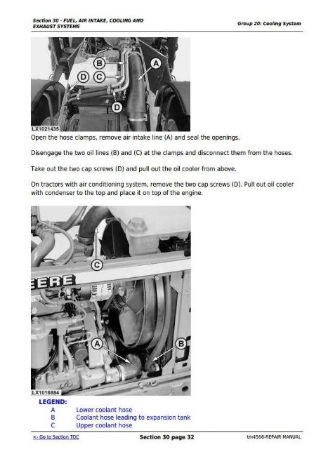
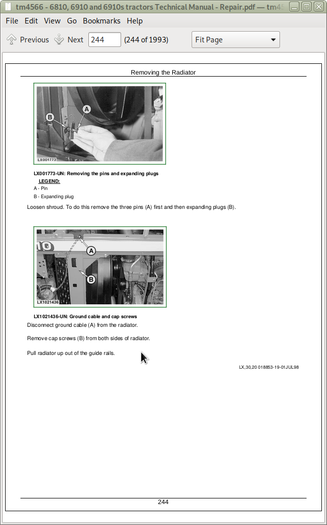
Removing the Radiator
Changing the Fan or the Viscous Fan Drive
Installing Radiator
Oil Cooler for Front PTO
Installing Oil Hoses
Relieve Drive Belt Tension
Replacing Drive Belt
Replacing the Drive Belt Tensioner
Repairing the Fan Console
Group 25: Cold Weather Starting Aids
Fuel Preheater
Electrical Starting Aid
Coolant Heater
Group 30: Exhaust System
General Information
Specifications
Exhaust to Top Left-Install Muffler
Installing the Muffler Pipe
Installing the Exhaust Pipe
Exhaust to Top Right - Installing the Muffler
Installing the Exhaust Pipe and Muffler Pipe
Section 40: ELECTRICAL SYSTEM
Group 05: Connectors
Special or Essential Tools
General
Using high-pressure washers
Disconnecting electrical circuits
Stripping wire ends
Installing a terminal
WEATHER PACK connector
METRI PACK connector with terminal lock at the rear
METRI PACK connector with terminal lock at the front
METRI PACK connector
Connectors for electronic control units
Connector for injection pump
Connector at CAN bus terminating resistor
CRIMP SNAP IN connectors
Connectors
CPC connectors
KOSTAL connectors
DEUTSCH Connectors
Changing terminals
Relay socket
Power distribution connectors
Load center
Load center
Group 10: Wiring Harnesses
Disconnecting electrical circuits
Ground Point Locations
Removing and Installing Engine Wiring Harness W3
Removing and Installing Engine Wiring Harness W3 (Tractors with AutoPowr Transmission or Tractor 6910S)
Removing and Installing Starting Aid Wiring Harness W27
Removing and Installing Starting Aid Wiring Harness W27 (Tractors with AutoPowr Transmission or Tractor 6910S)
Removing and installing worklight wiring harness W14 (front corner)
Removing and Installing FWD Axle Wiring Harness W36 (with TLS)
Removing and Installing Front PTO Wiring Harness W39
Removing and Installing Cab Wiring Harness W4
Removing and Installing Cab Wiring Harness W4 (Tractors with Power Shift Transmission)
Removing and Installing Cab Wiring Harness W4 (Tractor 6910S)
Removing and Installing Cab Wiring Harness W4 (Tractors with AutoPowr Transmission)
Removing and installing harness for 7-terminal power socket W29
Removing and installing harness for 3-terminal power socket W31
Removing and installing multi-function unit wiring harnesses W5, W6
Removing and Installing Air Brake Wiring Harness W54 (50 km/h Tractors)
Removing and installing the shift console wiring harness (Power Shift transmission) W45
Removing and Installing Electronic Control Unit Wiring Harness W34
Removing and Installing Electronic Control Unit Wiring Harness W34 (Tractors with AutoPowr Transmission or Tractor 6910S)
Removing and installing stepper motor driver wiring harness W35
Removing and Installing Cab Roof Wiring Harness W11
Removing and Installing Worklight Wiring Harness W18 (Cab)
Removing and installing wiper wiring harnesses W7, W10 and W38
Removing and installing air conditioning and fan wiring harness W8
Removing and Installing Transmission Wiring Harness W13
Removing and Installing Transmission Wiring Harness W13 (Tractors with AutoPowr Transmission)
Removing and Installing Transmission Wiring Harness W20 (Tractors with Electrical Reverser Control)
Removing and Installing Transmission Wiring Harness W44 (Tractors with Power Shift Transmission)
Group 15: Charging Circuit
Specifications
Repairing the Alternator
Disconnecting Electrical Circuit
Relieve Drive Belt Tension
Remove/Install the Alternator
Group 20: Starter Motor Circuit
Special or Essential Tools
Specifications
Repairing the Starting Motor
Disconnecting electrical circuits
Removing and Installing Starter Motor
Group 25: Fuses, Relays and Switches
Special or Essential Tools
Specifications
Note
Disconnecting electrical circuits
Load Center
Load Center on Tractors with AutoPowr Transmission
Replacing the Main Fuse
Replacing the Electrical Starting Aid Fuse
Replacing the Fuses (Electrical Starting Aid) on Tractors with AutoPowr Transmission or 6910S Tractors
Replacing the Fuse for the Injection Pump (Tractors with AutoPowr Transmission) or Tractor 6910S
Replacing the starting motor relay
Replacing the Starting Motor Relay on Tractor with AutoPowr Transmission or Tractor 6910S
Replacing the electrical starting aid relay
Replacing the Relay for Electrical Starting Aid on Tractor with AutoPowr Transmission or Tractor 6910S
Replacing the relays for Power Shift transmission
Replacing front PTO relay
Replacing the Air Brake Relay (on 50km/h Tractors)
Replacing the Relay for the Injection Pump (Tractors with AutoPowr Transmission) or Tractor 6910S
Replacing the main switch
Replacing Brake Switches
Replacing Brake Switches (on 50km/h Tractors)
Replacing the Braking Switches (Tractors with AutoPowr Transmission)
Replacing the light switch
Replacing the worklight switches
Replacing the switch for lights on cab frame
Replacing the switch for the beacon light
Replacing the hazard warning light switch
Replacing the handbrake switch
Replacing Switches on Multi-Function Unit
Replacing the Rear Window Wiper/Washer Switch
Replacing the windshield/rear window switches
Replacing the dome light door switch
Replacing the Park Lock Switch (Tractors with Electrical Reverser Control)
Replacing the Switch for Reverse Range Lockout (Tractors with Electrical Reverser Control)
Replacing the front wheel drive switch
Replacing the headland management (HMS) switch
Replacing the rear PTO preselector switch
Replacing the switch for AutoQuad transmission
Replacing the switch for AutoQuad II transmission
Replacing the Gear Selector Switch on PowrQuad Plus, AutoQuad and AutoQuad II Transmissions
Replacing the blower switch
Replacing switch of air conditioning system compressor
Replacing the differential lock switch
Replacing the PTO switch
Replacing switch for remote control of PTO
Replacing the Rockshaft Control Switch
Replacing the Cruise Control Potentiometer
Replacing the Cruise Control Potentiometer
Rockshaft control
Electrical actuation of the independent control valves
Group 30: Monitoring Systems
Note
Note
Disconnecting electrical circuits
Replacing the Sending Unit for Air Cleaner Restriction
Replacing the Engine Speed Sending Unit
Replacing the Sending Unit for Engine Oil Pressure
Replacing Coolant Temperature Sending Unit
Replacing Manifold Pressure Sending Unit (Power Shift transmission)
Replacing the Ground Speed Sending Unit
Replacing Acoustic Warning Signal Sending Unit
Replacing the Sending Unit for the Park Lock's Acoustic Alarm (Tractors with AutoPowr Transmission)
Group 40: Electrical Components
Note
Specifications
Disconnecting electrical circuits
Replacing the 7-Terminal Power Outlet Socket
Replacing the 3-terminal power outlet socket
Replacing the multiple power-outlet socket strip
Removing the wiper motor
Adjusting the headlights
Adjusting the lights on the cab frame
Worklights with xenon bulbs
Section 52: POWER SHIFT TRANSMISSION
Group 00: Removing and Installing the Power Shift Transmission
Special Tools
Dealer-Manufactured Special Tools
Specifications
Removing the Power Shift Transmission
Installing the Power Shift Transmission
Group 05: Shift Controls
Removing and Installing the Shift Control Assembly
Disassemble and Assemble Shift Control Assembly
Replace Encoder
Replace Switch Module
Adjusting the Parking Lock
Group 10: Power Shift Transmission
Special Tools
Service Equipment and Tools
Other Material
Specifications
General Repair Procedures
Transmission Components
Removing the Power Shift Transmission
Remove Transmission Front Cover/Front Valve Housing
Remove Front Valve Housing
Valves in Front Valve Housing
Valves in Transmission Front Cover
Remove Clutch Pedal Valve
Replace Shaft Seal of Traction Clutch Valve Shifter Lever
Repair Transmission Oil Pump
Install Front Valve Housing
Install Transmission Front Cover
Repair or Replace Electro-Hydraulic Valves
Remove Clutch Pack Assembly
Disassemble Clutch Pack
Assemble Clutch Pack
Install Clutch Pack Assembly
Remove and Disassemble CLO-BHI Pack
Assemble and Install CLO-BHI Pack
Remove and Disassemble Input Planetary Carrier Assembly
Assemble and Install Input Planetary Carrier Assembly
Disassemble Output Housing Module and Remove Output Planetary Carrier
Disassemble Output Planetary Carrier Assembly
Assemble Output Planetary Carrier Assembly
Remove and disassemble B5 Brake Pack
Assemble and Install B5 Brake Pack
Install Output Planetary Carrier and Assemble Output Housing Module
Group 15: Reduction Gearbox
Special Tools
Service Equipment and Tools
Specifications
General Repair Procedures
Remove Differential Drive Shaft
Install Differential Drive Shaft and Adjust Cone Point
Remove and Install Reduction Gear Shaft
Repair Lube Manifold
Remove and Install Tow Disconnect
Replace Transmission Lock Return Spring
Remove and Install Parking Lock
Section 53: AUTOPOWR TRANSMISSION
Group 00: Removing and Installing the AutoPowr Transmission
Special or Essential Tools
Specifications
Removing the AutoPowr Transmission
Installing the AutoPowr Transmission
Group 05: Transmission Shift Controls
Repairing the Speed Control Lever
Repairing the Reverser Control
Repairing the Clutch Actuation Mechanism
Repairing the Manual Park Lock Release Mechanism
Releasing the Park Lock Manually
Group 10: Input Housing
Special or Essential Tools
Specifications
Removing the Clutch Control Block
Removing the System Pressure Control Block and Oil Filter
Removing the Transmission Oil Pump
Repairing the Transmission Oil Pump
Installing the Transmission Oil Pump
Repairing the System Pressure Control Block
Installing the System Pressure Control Block and Oil Filter
Repairing the Clutch Control Block
Installing the Clutch Control Block
Replacing the Hydrostatic Speed Sending Unit
Group 15: Output Housing
Special or Essential Tools
Specifications
Removing Park Lock Control Block
Removing Locking Pawl of Park Lock
Installing Locking Pawl of Park Lock
Repairing the Park Lock Control Block
Installing Park Lock Control Block
Replacing the Transmission Speed Sending Unit
Replacing the Transmission Input Speed Sending Unit
Group 20: Assembling the Differential Drive Shaft
Specifications
Preliminary Work
Differential Drive Shaft - Cross-Sectional View
Removing the Differential Drive Shaft
Repairing the Differential Drive Shaft
Final Assembly
Section 55: POWRQUAD, POWRQUAD PLUS AND AUTOQUAD TRANSMISSIONS
Group 00: Removal and Installation of Transmission Components
Special Tools
Dealer-Manufactured Special Tools
Specifications
Removing the PowrQuad Module
Installing the PowrQuad Module
Removing the Creeper Transmission
Installing the Creeper Transmission
Removing the Range Transmission
Installing the Range Transmission
Group 05: Transmission Shift Controls
Specifications
Gear shift linkage without forward/reverse interlock (reverser control on shift console)
Gear shift linkage with forward/reverse interlock, from tractor serial number 260099, (reverser control on shift console)
Range shift linkage without forward/reverse interlock (reverser control on shift console)
Range shift linkage with forward/reverse interlock, from tractor serial number 260099, (reverser control on shift console)
Gear shift linkage (reverser control on steering column)
Range shift linkage (reverser control on steering column)
Range shift linkage (PowrQuad Plus and AutoQuad transmissions)
Installing transmission bowden cables
Reverser control linkage adjustment
Adjusting shift linkage and parking lock - reverser control on shift console
Adjusting the shift linkage and parking lock - reverser control on steering column
Adjusting the shift linkage and parking lock - PowrQuad Plus and AutoQuad transmissions
Clutch pedal adjustment
Group 10: PowrQuad Module
Special or Essential Tools
Service Equipment and Tools
Other Material
Specifications
Transmission components
Installing transmission in repair stand
Removing the transmission front cover
Removing the front valve housing from the transmission cover
Valves in front valve housing
Valves in the front transmission cover
Removing the clutch pedal valve
Installing the clutch pedal valve
Transmission pump - cross-sectional view
Repairing the transmission pump
Installing the front valve housing
Installing the front transmission cover
Removing the shift valve housing
Replacing the shaft seals and shifter levers
Replacing the shifter shafts and arms
Valves in the shift valve housing
Speed modulator valve - cross-sectional view
Planetary housing valves
Forward/reverse valve - cross-sectional view (mechanical reverser control)
Forward/reverse valve - cross-sectional view (electrical reverser control)
Speed valve - cross-sectional view
Assembling and installing the shift valve housing
Disassembling the planetary gear
Reconditioning the input planetary carrier
Disassembling the input planetary assembly
Disassembling the disk brake housing
Planetary carrier/tractor clutch - cross-sectional view
Reconditioning the planetary carrier/tractor clutch
Disassembling the planetary housing components
Reconditioning the direct drive clutch
Assembling the planetary housing components
Assembling the disk brake housing
Assembling the planetary carrier
Assembling the planetary gear/disk brake housing
Removing the stepper motor
Installing the stepper motor
Adjusting the stepper motor
Group 15: Creeper Transmission
Service Equipment and Tools
Other Material
Specifications
Preliminary Work
Removing Shifter Components
Repair Input/Output Drive Shaft
Remove and Install Countershaft
Install Input/Output Shaft Assembly
Final Assembly
Group 20: Range Transmission
Special Tools
Service Equipment and Tools
Other Material
Specifications
Repair Instructions
Preliminary Work
Range Transmission-Sectional View
Shifting Mechanism-Cross-Sectional View
Removing Differential Drive Shaft
Removing Drive Shaft
Differential Drive Shaft - Exploded View
Drive Shaft (30 KM/H; 18.5 MPH Version) - Exploded View
Drive Shaft (40 KM/H; 25 MPH Version) - Exploded View
Shifting Mechanism - Exploded View
Parking Lock - Exploded View
Repairing the Drive Shaft
Installing Drive Shaft
Adjusting Drive Shaft End Play
Install Differential Drive Shaft and Adjust Cone Point
Adjusting End Play of Differential Drive Shaft
Adjusting Shifting Mechanism
Repairing and Installing Shift Cover
Final Assembly
Section 56: DRIVE SYSTEMS
Group 00: Removal and Installation of Components
Essential Tools
Self-manufactured tools
Specifications
Removing the differential housing
Installling the differential housing
Removing the final drives
Installing the final drives
Removing the FWD clutch
Installing the FWD clutch
Removing the rear PTO
Installing the rear PTO
Removing the front PTO
Installing the front PTO
Group 05: U-Jointed Shafts and Torsion Damper
Specifications
Removing the U.j. Shaft (FWD)
Reconditioning the U.j. Shaft (FWD)
Installing the U.j. Shaft (FWD)
Removing the U.j. Shaft (Engine)
Removing the Torsion Damper
Changing the Torsion Damper Bearings
Installing the Torsion Damper
Installing the U.j. Shaft (Engine)
Group 10: Front-Wheel Drive Clutch
Special Tools
Service Equipment and Tools
Specifications
Repair Instructions
Preliminary Work
Removing Clutch
Disassemble Clutch
Assembling Clutch
Installing Clutch
Adjust End Play
Adjusting the Brake Band
Final Assembly
Group 15: Differential
Special Tools
Service Equipment and Tools
Specifications
Repair Instructions
Preliminary Work
Removing the Differential
Disassembling the Differential
Assembling the Differential
Installing the Differential
Adjusting Differential Preload
Adjusting Backlash
Final Assembly
Group 20: Hydraulic Pump Drive
Special Tools
Service Equipment and Tools
Specifications
Remove and Disassemble Pump Drive Pinion Gear
Remove and Disassemble Pump Drive Gear
Assemble and Install Pump Drive Gear
Assemble and Install Pump Drive Pinion
Group 25: Final Drives
Special Tools
Service Equipment and Tools
Other Material
Specifications
Repair Instructions
Preliminary Work
Remove Planet Pinion Carrier
Disassemble Planet Pinion Carrier
Assemble Planet Pinion Carrier
Remove Axle Housing
Disassemble and Assemble Axle Housing
Disassemble and Assemble Axle Shaft
Install Axle Housing
Install Planet Pinion Carrier and Check Rolling Drag Torque
Final Assembly
Group 30: Rear PTO Options
Special Tools
Service Equipment and Tools
Specifications
Repair Instructions
Repair Rear PTO
Remove and Disassemble Countershaft
Assemble and Install Countershaft
Remove and Disassemble Output Shaft
Assemble and Install PTO Output Shaft
Remove PTO Shifter
Install PTO Shifter
Replacing Oil Seal on PTO Output Shaft
Remove Modulating Valve
Disassemble and Assemble Modulating Valve
Install Modulating Valve
Changing and Adjusting the Bowden Cable
Adjusting the Indicator Light Switch
Group 35: Front PTO
Service Equipment and Tools
Other Material
Specifications
General Repair Procedures
Front PTO-Cross-Sectional View
Repairing Solenoid Valve
Removing the Modulating Valve
Repairing the Modulating Valve
Installing the Modulating Valve
Replacing PTO Speed Sending Unit
Changing/Washing the Filter
Checking the Pressure Regulating Valve
Checking the Check Valves
Removing the Valve Plate
Disassembling Front PTO
Removing the Output Shaft Assembly
Repair Oil Pump
Assemble Oil Pump
Repairing the PTO Clutch
Repairing the PTO Brake
Installing Clutch and Brake
Repairing Intermediate Gear Shaft (PTO Rotating Counterclockwise)
Repairing the Drive Shaft
Assemble Drive Shaft, Shift Device and Front PTO
Adjusting Taper Roller Bearing of Drive Shaft
Adjusting Taper Roller Bearing of Output Shaft
Adjusting Taper Roller Bearing of Intermediate Gear Shaft
Installing Front PTO
Group 40: Front Implement Drive
Special Tools
Specifications
Front PTO Drive, Replace Damper
Section 60: STEERING AND BRAKES
Group 05: Hydrostatic Steering
Special Tools
Specifications
Preliminary Work
Removal
Disassembling the Steering Valve
Exploded View of Steering Valve
Assembling the Steering Valve
Adjusting the Double-Acting Shock Valves
Steering Wheel and Column-Exploded View
Repairing the Steering Column
Installation
Group 10: Brake Valve (Power Fill Brakes)
Special Tool (Dealer-Fabricated)
Specifications
Preliminary Work
Removing the Brake Valve
Brake Valve, Disassembly
Exploded View
Assembling the Brake Valve
Installing the Brake Valve
Adjusting the Brake Pedals
Adjust Brake Switches
Final Assembly
Bleeding the Brakes
Group 10A: Brake Valve (with MFWD and Disk Brake)
Special Tool (Dealer-Fabricated)
Specifications
Preliminary Work
Removing the Brake Valve
Disassembling the Brake Valve
Exploded View
Assembling the Brake Valve
Installing the Brake Valve
Adjusting the Brake Pedals
Adjusting the Brake Switches
Final Assembly
Bleeding the Brakes
Group 15: Rear Brakes
Specifications
Preliminary Work
Removing the Rear Brakes
Rear Brakes-Exploded View
Repairing the Rear Brakes
Installing the Rear Brakes
Final Assembly
Bleeding the Brakes (Brake Valve, Power-Fill Brakes and MFWD and Disk Brake)
Group 20: Handbrake
Specifications
Preliminary Work
Removing the Handbrake
Exploded View of Handbrake - 6810 Tractor
Exploded View of Handbrake - 6910 Tractor
Installing the Handbrake
Adjusting the Brake Band
Final Assembly
Handbrake Components
Replacing the Handbrake Cable
Adjusting the Handbrake
Group 25: Hydraulic Trailer Brake
Special Tools
Specifications
Repair Instructions
Replacing Trailer Brake Valve
Cleaning Trailer Brake Valve
Cleaning the Screen
Replacing the Check Valve
Bleeding Trailer Brake Valve
Checking Trailer Brake Valve
Adjusting Trailer Brake Valve
Group 30: Air Brakes
Special Tools
Specifications
General Information
Screw Union Installation
Changing the Compressor
Gaskets for the Compressor
Change Compressed Air Tank
Changing the Pressure Control Valve
Changing the Preload Valve
Changing the Trailer Control Valve
Change Pressure Gauge
Changing the Coupling Ends
Visual and Operational Checks
Test sequence
Checking the System for Leaks
Check Handbrake (Dual-Line Brakes)
Check Handbrake (Single-Line Brakes)
Adjusting the Handbrake
Checking the “Supply” Coupling End
Section 70: HYDRAULIC SYSTEM
Group 05: Controls
General Information
Specifications
Replacing and Adjusting the SCV Actuating Elements
Install Multi-Function Lever
Adjusting the Multi-Function Lever
Group 10: Hydraulic Pump and Charge Oil Pump
Service Equipment and Tools
Other Material
Specifications
Repair Instructions
Removing the Charge Pump
Disassembling the Charge Pump
Assembling the Charge Pump
Installing the Charge Pump
Checking the Lube Oil Valve
Restrictor in Oil Tank
Check Valve in Oil Leak-Off Line
Changing the Hydraulic Pump Controller
Hydraulic Pump Controller - Exploded View
Adjusting the Controller
Removing the Hydraulic Pump
Installing the Hydraulic Pump
40 cm3 (2.4 cu.in.) Hydraulic Pump - Exploded View
25 cm3 (1.5 cu.in.) Hydraulic Pump - Exploded View
Disassemble, Inspect and Assemble Hydraulic Pump
Adjust Swashplate Bearing Preload
Adjust Shaft Bearing Preload
Group 15: Valves
Special Tools
Special Tools (Dealer Fabricated)
Specifications
Repair Instructions
Direct Control of Rockshaft
Removing the Rockshaft Valve
Repairing the Rockshaft Valve
Depth to Which Raising and Lowering Valves Are Screwed In
Changing the Stepper Motor
Centering the Stepper Motor
Installing the Rockshaft Valve
Installing the Shuttle Valves
Removing the Main Block
Main Block-Exploded View
Repairing the Main Block
Installing the Main Block
Checking Oil Filter Head
Power Beyond Application Valve-Exploded View
Connecting the Power Beyond Application Valve
Adjusting the Power Beyond Application Valve
Converting the Power Beyond Application Valve
Connecting the Power Beyond Application Valve
Adjusting the Power Beyond Application Valve
Group 20: Rockshaft and Rockshaft Cylinder (up to Tractor Serial No. 260141)
Special Tools
Specifications
Electronic Hitch Control Unit (HCU)
Changing the Position Sensor
Cross-Section and Exploded View - Lift Cylinder
Removing and Installing the Lift Cylinders
Rockshaft - Exploded View
Replacing the Bushings on the Rockshaft Housing
Group 20A: Rockshaft and Rockshaft Cylinder (from Tractor Serial No. 260142)
Specifications
Electronic Hitch Control Unit (HCU)
Removing the Position Sensor and Toothed Segment
Attaching the Toothed Segment
Position Sensor - Exploded View
Installing the Position Sensor
Removing the Rockshaft Cylinders
Repairing the Rockshaft Cylinders
Installing the Rockshaft Cylinders
Rockshaft - Exploded View
Removing the Rockshaft
Installing the Rockshaft
Group 25: Three-Point Hitch
Other Material
Draft Sensor and Draft Link Support - Exploded View
Changing the Draft Sensor and Draft Link Support
Group 30: Selective Control Valves and Couplers
Special Tools (Dealer Fabricated)
Other Material
Specifications
Repair Instructions
SCV Identification
Removing Selective Control Valves
100 Series Selective Control Valve-Exploded View
Repairing 100 Series Selective Control Valve
200 Series Selective Control Valve-Exploded View
300 Series Selective Control Valve-Exploded View
Replacing Control Knobs
Inspect the Check Valves - 200 and 300 Series
Inspect Pressure Compensator Valve-300 Series
Inspect Metering Valve-300 Series
Inspect Metering Valve-200 Series
Repairing 300 Series Selective Control Valve Spool
Repairing 200 Series Selective Control Valve Spool
Installing Selective Control Valves
Install Shuttle Valves at the SCV
Installing the Left-Hand Endplate
Installing the Right-Hand Endplate
Adjusting LS Relief - L.H. Endplate with extra LS Connector for External Consumers
Adjusting LS Relief - R.H. Endplate with Extra Connectors for External Consumers
Adjusting the Kickout Relief Valve Detent - 300 Series SCV
Changing Couplers
DeLuxe Coupler - Exploded View
Repairing the Deluxe Coupler
Checking Couplers for Leaks
Group 35: Independent Control Valve
Other Material
Specifications
Repair Instructions
Removing the Independent Control Valve
Repairing the Control Valves (Mechanical Actuation)
Repairing the Control Valves (Electrical Actuation)
Inlet Plate with Pressure-Limiting Valve
Assembling the Control Valve
Installing the Control Valve
Section 80: MISCELLANEOUS
Group 00: Removal and Installation of Components
Special Tools
Dealer Fabricated Tools
Specifications
Removing the Main Frame (Tractors Without TLS Front Axle)
Installing the Main Frame (Tractors Without TLS Front Axle)
Removing Main Frame (Tractors With TLS Front Axle)
Installing Main Frame (Tractors With TLS Front Axle)
Removing the Front Wheel Drive Axle
Installing the Front-Wheel Drive Axle
Removing the Front Wheel Drive Axle With TLS
Installing the Front Wheel Drive Axle With TLS
Removing the Front Axle Support (Tractors Without TLS Front Axle)
Installing the Front Axle Support (Tractors Without TLS Front Axle)
Removing the Front Axle Support (Tractors With TLS Front Axle)
Installing the Front Axle Support (Tractors With TLS Front Axle)
Group 05: Main Frame
Specifications
Removing and Installing the Main Frame
Group 10: Front and Rear Wheels
Special Tools
Specifications
Removing a Wheel (Front or Rear)
Attaching Front Wheel
Attaching Rear Wheel
Group 15: Trailer Hitch and Swinging Drawbar
Specifications
Installing the Trailer Mounting for Center Link
Installing Guide Rails (with Height-Adjustable Trailer Hitch)
Height-Adjustable Trailer Hitch - Exploded View
Repairing Automatic Trailer Hitch (Two-Lever Operation)
Repairing Automatic Trailer Hitch (One-Lever Operation)
Remote Control for Automatic Trailer Hitch
Swinging Drawbar - Exploded View
Swinging Drawbar (with Pick-Up Hitch)
Group 20: Triple Link Suspension (TLS) of FWD Axle
General Information
Special Tools
Service Equipment and Tools
Other Material
Specifications
Relieving Pressure in the Hydraulic System
Removing/Installing the Oscillation Limiter
Removing the Panhard Link
Installing the Panhard Link
Suspended Front Axle (SFA) Controller
Removing the Position Sensor
Repairing the Position Sensor
Installing the Position Sensor
Adjusting the Sensor Rod
Removing the Hydraulic Cylinder
Repairing the Hydraulic Cylinder
Installing the Hydraulic Cylinder
Removing the Control Valve Block
Installing the Control Valve Block
Repairing the Solenoid Valves
Repairing the Pressure-Regulating Valve
Repairing the Pressure-Relief Valve
Repairing the Electro-Hydraulic Control Valve Plugs
Repairing the Bleed Valves
Repairing the Distributor Block
Removing and Installing the Accumulator
Repairing the Accumulator
Removing the Bearing Support
Installing the Bearing Support
Group 25: Pick-Up Hitch
Specifications
Other Material
Installing the Upper Frame
Frame Assembly - Exploded View
Operating Lever and Lift Links - Exploded View
Hydraulic Parts
Repairing the Retainer Spring
Repairing the Latch Housing
Repairing the Hydraulic Cylinder
Adjusting the Lift Links
Adjusting the Guide Stop
Adjusting the Locking Pin
Operational Check
Section 90: OPERATOR'S CAB
Group 00: Tilting, Removing and Installing the Operator's Cab
Special Tools
Specifications
Tilting the Operator's Cab Upward
Tilting the Operator's Cab Downward
Removing the Operator's Cab
Installing the Operator's Cab
Group 05: Controls and Instruments
Replacing Bulbs on the Instrument Unit
Removing Control Unit
Removing Control Unit for the Lighting System
Important Instructions
Replacing Electronic Control Unit (BCU)
Replacing Electronic Control Unit (RCU)
Replacing Electronic Control Unit (SFA)
Replacing Electronic Control Unit (ECU)
Replacing the Bus Resistors
Replacing Transmission Control Unit (PST)
Replacing the PPST/E-ICV Control Unit (PEC)
Replacing the Electronic Control Unit (UIC/PLC)
Replacing the Electronic Control Unit (TCU)
Replacing the Performance Monitor (PRF)
Replacing Instrument Unit (BIF)
Group 10: Electonic Hitch Control Components
Disconnecting Electrical Circuit
Replacing the Hitch Control Unit (HCU)
Replacing the Operation Unit
Group 15: Air Conditioning System
Special Tools
Specifications
Torques for Tightening Refrigerant Hoses
Safety At Work
Handling Refrigerant
In an Emergency
Safety Equipment
Storage of Refrigerant Containers
R134A Refrigerant
Important Note
Discharging the System
Evacuating the System
Filling with Refrigerant Oil
Instructions for Starting Up the DENSO Air-Conditioning Compressor
Filling the System
Topping Up a Partly Discharged System
Leak Test
Removing the Compressor
Checking Level in the Compressor
Disassembling the Compressor Clutch
Checking Clutch Hub Clearance
Checking the Compressor Manifold
Installing the Compressor
Routing the Air-Conditioning Hoses
Removing and Installing the Condenser
Removing and Installing the Receiver-Drier
Removing and Installing the Evaporator and Expansion Valve
Replacing the Expansion Valve
Installing Condensation Water Drain Hoses
Removing and Installing the Thermostat Switch
Adjusting Thermostat Switch Bowden Cables
Removing and Installing the High/Low Pressure Switch
Group 20: Heating System
Ventilation and Heater-Exploded View
Removing and Installing Fan and Radiator
Removing and Installing the Heater Valve
Adjusting Heater Valve Bowden Cables
Removing the Cab Air Filter
Replacing Recirculating Air Filter
Group 25: Operator's Cab
Specifications
Removing Cab Frame
Cab Mounting Torques
Removing Outer Roof
Removing Hatch
Installing Windshield
Installing Rear Window
Installing Door Lock
Replacing Handrail or Rear View Mirror
Adjusting Window Contact Pressure
Removing the Cab Door
Installing the Cab Door
Removing Inner Roof Trim
Group 30: Seats
Specifications
Comfort Seat MSG85
Air Comfort Seat MSG95A-00, Lower Section
Passenger Seat, Exploded View
Group 35: Components for Radio Installation
Radio, Loudspeakers and Aerial, Exploded View
Section 99: SPECIAL TOOLS (DEALER-FABRICATED)
Group 05: Special Tools (Dealer-Fabricated)
Lifting Device
Lifting Device
Adapter
Holding Device
Suspension Eyes for Operator's Cab
Holding Tool
DFRW79 - Piston Holding Tool
Socket Wrench Insert
Driver
DFRW29-Final Drive Housing Adapter
DFRW30-Axle Jacking Tool
Socket Wrench Insert
Special Key
Installation tool
Tube
Unlocking Device
Suspension Device
![]()