
John Tractors 6020, 6020SE, 6120, 6120SE, 6220, 6220SE, 6320, 6320SE, 6420, 6420S, 6420SE, 6520, 6520SE, 6620 Repair Service Manual (TM4750)
Complete service repair manual for John Deere 2WD or MFWD Tractors 6020, 6120, 6220, 6320, 6420, 6520, 6620 (S,SE) European models, with all the workshop information to maintain, repair, and service like professional mechanics.
John Deere 6020, 6120, 6220, 6320, 6420, 6420S, 6520, 6620 & SE Tractors workshop service repair manual includes:
* Numbered table of contents easy to use so that you can find the information you need fast.
* Detailed sub-steps expand on repair procedure information
* Numbered instructions guide you through every repair procedure step by step.
* Notes, cautions and warnings throughout each chapter pinpoint critical information.
* Bold figure number help you quickly match illustrations with instructions.
* Detailed illustrations, drawings and photos guide you through every procedure.
* Enlarged inset helps you identify and examine parts in detail.
TM4750 - John Deere 6020, 6120, 6220, 6320, 6420, 6420S, 6520, 6620 & SE Tractors Technical Manual (Repair).pdf
TM4750 - John Deere 6020, 6120, 6220, 6320, 6420, 6420S, 6520, 6620 & SE Tractors Technical Manual (Repair).epub
PRODUCT DETAILS:
Total Pages: 2,986 pages
File Format: PDF/EPUB/MOBI/AZW (PC/Mac/Android/Kindle/iPhone/iPad; bookmarked, ToC, Searchable, Printable)
Language: English
For complete service information also see:
6020 to 6920S Tractors and SE Tractors Operation and Tests TM4741
6020 to 6920S Tractors and SE Tractors Diagnostics TM4726
Front-Wheel Drive Axles (AS and MS Series) CTM4687
Front-Wheel Drive Axles (700 Series) CTM4820
POWERTECH Diesel Engines CTM104
Mechanical Fuel Injection Systems CTM207
Electronic Fuel Injection Systems Level 1 CTM284
Electronic Fuel Injection Systems Level 4 CTM170
Electronic Fuel Injection Systems Level 11 CTM220
Electronic Fuel Injection Systems Level 12 CTM331
Alternators and Starting Motors (available in English only) CTM77
MAIN SECTIONS
Foreword
Version date
Safety
Safety Measures
General Information
Specifications
Tune-Up
Predelivery Inspection
Engine
Removal and Installation of Components
FUEL, AIR INTAKE, COOLING AND EXHAUST SYSTEMS
Speed Control Linkage
Fuel System
Air Intake System
Cooling System
Cold-Weather Starting Aids
Exhaust System
Electrical System
Connectors
Wiring Harnesses
Charging Circuit
Starter Motor Circuit
Fuses, Relays and Switches
Monitoring Systems
Electrical Components
SyncroPlus Transmission
Removal and Installation of Components
Transmission Shift Controls
Perma Clutch II Module
Gear Transmission
Power Reverser Transmission
Removal and Installation of Components
Transmission Shift Controls
Power Reverser Module
Gear Transmission
AutoPowr/IVT Transmission
Component Removal and Installation
Transmission Shift Controls
Input Housing
Output Housing
Differential Drive Shaft Assembly
PowrQuad, PowrQuad Plus, AutoQuad and AutoQuad Plus Transmissions
Component Removal and Installation
Transmission Shift Controls
PowrQuad Module
Creeper Transmission
Option Transmission
Range Transmission
Power Train (without Transmission)
Removal and Installation of Components
U-Jointed Shafts and Torsion Damper
Front-Wheel Drive Clutch
Differential
Hydraulic Pump Drive
Final Drives
Rear PTO Options
Front PTO
Front Implement Drive
Steering and Brakes
Hydrostatic Steering
Steering Cylinders
Brake Valve
Rear Wheel Brakes
Handbrake
Hydraulic Trailer Brake
Air Brakes up to Serial No. 398655
Air Brakes from Serial No. 398656
AutoTrac
Hydraulic System
Controls
Hydraulic Pump and Charge Pump (PFC Hydraulic System)
Hydraulic Pump (PC Hydraulic System)
Valves
Rockshaft
Selective Control Valves and Couplers
Independent Control Valve (ICV)
Miscellaneous
Removal and Installation of Components
Main Frame
Front Axle
Front Wheels, Rear Wheels and Fenders
Trailer Mounting and Swinging Drawbar
Triple Link Suspension (TLS) of Front-Wheel Drive Axle
Pick-Up Hitch
Operators's Cab
Removal and Installation of Components
Controls and Instruments
Air Conditioning System
ClimaTrak
Heating System
Seats
Operators's Cab
Cab Suspension
Special Tools
Special Tools (Dealer-Fabricated)
Special Tools (available from the dealer)
tm4750 - 6020 to 6620 Tractors
Table of Contents
Foreword
Version date
Section 05: Safety
Group 05: Safety Measures
Recognize Safety Information
”Important” Information
”Note” Information
Prevent Machine Runaway
Handle Fluids Safely-Avoid Fires
Prevent Battery Explosions
Prepare for Emergencies
Prevent Acid Burns
Avoid High-Pressure Fluids
Service Cooling System Safely
Remove Paint Before Welding or Heating
Avoid Heating Near Pressurized Fluid Lines
Work In Ventilated Area
Wear Protective Clothing
Practice Safe Maintenance
Park Machine Safely
Use Proper Lifting Equipment
Construct Dealer-Made Tools Safely
Support Machine Properly
Work in Clean Area
Illuminate Work Area Safely
Service Machines Safely
Use Proper Tools
Service Tires Safely
Service Front-Wheel Drive Tractor Safely
Safety Information - Air Brake System
Avoid Eye Contact With Radar
Keep ROPS Installed Properly
Replace Safety Signs
Dispose of Waste Properly
Live With Safety
Safety Measures on Electronic Control Units
Section 10: General Information
Group 05: Specifications
Specifications (Summary of References)
Engine
Cooling System
Injection pump (Lucas)
Injection pump (Bosch VP44)
Level 11 Electronic Fuel System with HPCR (Denso)
Level 12 Electronic Fuel System With Stanadyne DE10 Pump
Air Intake System
Electrical System
Hydrostatic Steering System
AutoTrac
Clutch
AutoPowr/IVT transmission
PowrQuad and PowrQuad Plus Transmissions
AutoQuad Transmission
Power Reverser
SyncroPlus Transmission
Creeper transmission
Rear PTO
Front PTO
Differential assembly
Differential lock
Final drives
Front-Wheel Drive
FWD axle with TLS
Cab Suspension:
Hydraulic Brakes
Handbrake
Parking Lock
Hydraulic System with Axial Piston Pump
Hydraulic System with Gear-Driven Pump
Rockshaft
Front Hitch
Ground Speeds
Front and Rear Wheels
Dimensions and Weights
Capacities
Handling and Storing Diesel Fuel
Diesel Fuel
Lubricity of Diesel Fuel
Diesel Engine Break-In Oil
Diesel Engine Oil (Engine Serial Number up to 799999)
Diesel Engine Oil (Engine Serial Number from 800000)
Transmission and Hydraulic Oil
Front-Wheel Drive Axle Oil
Diesel Engine Coolant
Supplemental Coolant Additives
Grease
Oil Filters
Mixing of Lubricants
Lubricant Storage
Operating in Warm Temperature Climates
Alternative and Synthetic Lubricants
Unified Inch Bolt and Screw Torque Values
Metric Bolt and Screw Torque Values
Hydraulic system inch fitting torques
Hydraulic system metric fitting torques
Product Identification and Sub-Assembly Serial Numbers
Engine serial number
Transmission serial number
Front wheel drive axle serial number
Operator's cab serial number
Operator's seat serial number
Sub-assembly serial numbers
Group 10: Tune-Up
General References, Tune-Up
Specifications
Using High-Pressure Washers
Preliminary Engine Test
Tractor Tune-Up
Removing and Cleaning the Primary Air Cleaner Element
Checking the Air Cleaner Safety Element
Installing the Primary Filter Element
Checking the Air Intake System Connections for Leaks
Checking the Crankcase Vent Hose for Clogging
Cleaning the Radiator Grille Screen
Keeping the Radiator Screen Clean
Checking the Caps on the Expansion Tank
Checking the Radiator for Leaks
Checking the Engine Thermostat
Check Operation of Fuel Transfer Pump
Checking the Fuel Filter
Bleeding the fuel system (tractors NOT equipped with Bosch VP44 injection pump
Bleeding the fuel system (with Bosch VP44 injection pump)
Checking the fuel filter (with Bosch VP44 injection pump)
Checking the Fuel Filter (With Denso/Stanadyne Injection Pump; Stage II Engines according to 97/68/EC)
Clean the water trap
Run the Engine until it is Warm, and Check Engine Speeds
Check Setting of Fuel Injection Pump
Check setting of speed control linkage
Cleaning the Battery, Cables and Battery Box with a Clean Cloth
Check the Neutral Start Circuit
Check operation of starting motor
Checking the lighting circuit
Final Engine Check
Tractor Operation Check
Group 15: Predelivery Inspection
Predelivery Inspection
Section 20: Engine
Group 00: Removal and Installation of Components
Specifications
Removing the Engine
Installing the Engine
Section 30: FUEL, AIR INTAKE, COOLING AND EXHAUST SYSTEMS
Group 05: Speed Control Linkage
Speed Control Linkage (Summary of References)
General Information
Specifications
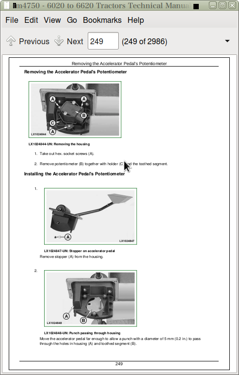
Adjusting the Hand Throttle Lever and Accelerator Pedal
Adjusting the Speed Control Linkage
Hand Throttle Lever-Exploded View
Accelerator Pedal On Tractors With Low Platform
Accelerator Pedal, with Mechanical Speed Control
Accelerator Pedal, With Electronic Speed Control (”Cruise Control”)
Adjusting the Accelerator Pedal (6420S)
Changing the Accelerator Pedal's Potentiometer
Replacing the Accelerator Pedal Assembly (AutoPowr/IVT)
Removing the Accelerator Pedal's Potentiometer
Removing the Hand Throttle's Potentiometer
Group 10: Fuel System
Fuel System (Summary of References)
General Information
Special Tool (Dealer-Fabricated)
Removing the Fuel Tank
Installing the Fuel Tank
Replacing the Fuel Gauge Sending Unit
Replace the Fuel Transfer Pump
Changing the Fuel Filter
Bleeding the Fuel System
Bleed the Air from the Fuel System (with Denso/Stanadyne Injection Pump)
Installing Check Valve in Fuel System
Install the Check Valve in the Fuel System (with Denso/Stanadyne injection pump; Stage II engines to 97/68/EC)
Group 15: Air Intake System
Air Intake System (Summary of References)
General Information
Air filter - Exploded view
Replacing the Sending Unit for Air Cleaner Restriction (B02)
Group 20: Cooling System
Cooling System (Summary of References)
General Information
Specifications
Removing and Installing the Ring-Shaped Cooler
Removing the Radiator
Change the Fan or the Viscous Fan Drive
Remove and Install the Intercooler
Remove and Install the Intercooler (Stage II engines to 97/68/EC)
Removing and Installing the Expansion Tank
Removing and Installing the Thermostat Valve
Installing the Radiator
Filling the Cooling System with Coolant
Relieving Tension on the Drive Belt
Replacing the Drive Belt
Replacing the Drive Belt Tensioner
Repairing the Fan Console
Remove and Install Fan Console (with Mechanical Coolant Pump)
Group 25: Cold-Weather Starting Aids
Fuel Preheater
Electrical Starting Aid
Coolant Heater
Group 30: Exhaust System
Exhaust System (Summary of References)
General Information
Specifications
Exhaust to Top Right
Exhaust to Bottom Right
Section 40: Electrical System
Group 05: Connectors
Connectors - Summary of References
Special Tools
General
Using high-pressure washers
Disconnecting electrical circuits
Stripping Wire Ends
Installing a Terminal
WEATHER PACK Connectors
METRI PACK Connector with Terminal Lock at the Rear
METRI PACK Connector with Terminal Lock at the Front
METRI PACK Connectors
Connector at CAN Bus Terminating Resistor
Connectors for Electronic Control Units
Connectors
CRIMP SNAP IN connectors
KOSTAL Connectors
DEUTSCH Connectors
Individual Terminals
Connector for Bosch VP44 Injection Pump
Fuse and Relay Boxes on Tractors with Operator's Cab
Fuse and Relay Box on Tractors with Open Operator's Station and SE Tractors
Group 10: Wiring Harnesses
Wiring Harnesses for 6120, 6220, 6320, 6420 and 6520 Tractors with PowrQuad Plus Transmission and Stage I Engine to 97/68/EC - Recondition (Summary of References)
Wiring Harnesses for 6320, 6420 and 6520 Tractors with AutoQuad Transmission and Stage I Engine to 97/68/EC - Recondition (Summary of References)
Wiring Harnesses for 6420S and 6620 Tractors with PowrQuad Plus or AutoQuad Transmissions and Stage I Engine to 97/68/EC - Recondition (Summary of References)
Wiring Harnesses for Tractors with PowrQuad Plus or AutoQuad Transmissions and Stage II Engine to 97/68/EC - Recondition (Summary of References)
Wiring Harnesses for 6120 and 6220 Tractors from Serial No. 398656 - Recondition (Summary of References)
Wiring Harnesses for 6320, 6420, 6420S, 6520, 6620, 6820, 6920 and 6920S Tractors with PowrQuad Plus or AutoQuad Plus Transmission from Serial No. 398656 - Recondition (Summary of References)
Wiring Harnesses for Tractors with AutoPowr/IVT Transmission and Stage I Engine to 97/68/EC - Recondition (Summary of References)
Wiring Harnesses for Tractors with AutoPowr/IVT Transmission and Stage II Engine to 97/68/EC - Recondition (Summary of References)
Wiring Harnesses for Tractors with AutoPowr/IVT Transmission from Serial No. 398656 - Recondition (Summary of References)
Wiring Harnesses for Tractors with Open Operator's Station and Stage I Engine to 97/68/EC - Recondition (Summary of References)
Wiring Harnesses for Tractors with Open Operator's Station from Serial No. 399888 and Stage I Engine to 97/68/EC - Recondition (Summary of References)
Wiring Harnesses for Tractors with Open Operator's Station and Stage II Engine to 97/68/EC - Recondition (Summary of References)
Wiring Harnesses for Tractors with Open Operator's Station from Serial No. 399888 and Stage II Engine to 97/68/EC - Recondition (Summary of References)
Wiring Harnesses for SE Tractors with Stage I Engine to 97/68/EC - Recondition (Summary of References)
Wiring Harnesses for SE Tractors from Serial No. 391068 with Stage I Engine to 97/68/EC - Recondition (Summary of References)
Wiring Harnesses for SE Tractors with Stage II Engine to 97/68/EC - Recondition (Summary of References)
Wiring Harnesses for SE Tractors from Serial No. 391068 with Stage II Engine to 97/68/EC - Recondition (Summary of References)
Disconnecting electrical circuits
Ground Point Locations
Removing and Installing Harness W01 - Power Supply
Remove and Install Harness W01 - Power Supply (Open Operator's Station)
Removing and Installing Harness W01 - Power Supply (SE Tractors)
Removing and Installing Harness W02 - Engine Wiring Harness for Stage I Engine to 97/68/EC (without Engine Control or with Level 1 ECU)
Removing and Installing Harness W02 - Engine Wiring Harness for Stage I Engine to 97/68/EC (ECU Level 4)
Removing and Installing Harness W02 - Engine Wiring Harness for Stage II Engine to 97/68/EC (ECU Level 11)
Removing and Installing Harness W02 - Engine (Level 11 ECU) from Serial No. 398791
Removing and Installing Harness W02 - Engine (Level 12 ECU) from Serial No. 398656
Removing and Installing Harness W02 - Engine Wiring Harness for Stage I Engine to 97/68/EC (Open Operator's Station)
Removing and Installing Harness W02 - Engine Wiring Harness for Stage II Engine to 97/68/EC (ECU Level 12) (Open Operator's Station)
Removing and Installing Harness W02 - Engine Wiring Harness for Stage I Engine to 97/68/EC (SE-Tractors)
Removing and Installing Harness W02 - Engine Wiring Harness for Stage II Engine to 97/68/EC (ECU Level 12) (SE-Tractors)
Removing and Installing Harness W03 - Wiring Harness - Starting Aid for Stage I and II Engines to 97/68/EC (without Engine Control or with Level 1 or 12 ECUs)
Remove and Install Harness W03 - Starting Aid (Level 12 ECU) from Serial No. 398656
Removing and Installing Harness W03 - Starting Aid for Stage I and II engines to 97/68/EC (Level 4 or 11 ECUs)
Removing and Installing Harness W03 - Starting Aid (Level 11 ECU) from Serial No. 398656
Removing and Installing Harness W03 - Starting Aid for Stage I and II engines to 97/68/EC (Level 4 or 11 ECUs) (AutoPowr/IVT transmission)
Removing and Installing Harness W03 - Starting Aid (Level 11 ECU) (AutoPowr/IVT transmission) from Serial No. 398656
Removing and Installing Harness W03 - Starting Aid (Level 12 ECU) from Serial No. 398656
Removing and Installing Harness W04 - Headlights
Removing and Installing Harness W06 - Front-Wheel Drive Axle with TLS
Removing and Installing Harness W07 - Front PTO
Removing and Installing Harness W08 - Cab, with Stage I Engine to 97/68/EC
Removing and Installing Harness W08 - Cab, with Stage II Engine to 97/68/EC
Removing and Installing Harness W08 - Cab from Serial No. 398656
Removing and Installing Harness W08 - Cab, with Stage I engine to 97/68/EC (AutoPowr/IVT transmission)
Removing and Installing Harness W08 - Cab, with Stage II engine to 97/68/EC (AutoPowr/IVT transmission)
Removing and Installing Harness W08 - Cab (AutoPowr/IVT Transmission) from Serial No. 398656
Removing and Installing Harness W08 - Open Operator's Station, with Stage I Engine to 97/68/EC
Removing and Installing Harness W08 - Open Operator's Station, with Stage II Engine to 97/68/EC
Removing and Installing Harness W08 - Open Operator's Station from Serial No. 399888
Removing and Installing Harness W08 - Cab, with Stage I Engine to 97/68/EC (SE-Tractors)
Removing and Installing Harness W08 - Cab, with Stage II Engine to 97/68/EC (SE-Tractors)
Removing and Installing Harness W08 - Cab (SE Tractor) from Serial No. 391068
Removing and Installing Harness W09 - Cowl, with Stage I Engine to 97/68/EC
Removing and Installing Harness W09 - Cowl, with Stage II Engine to 97/68/EC
Removing and Installing Harness W09 - Cowl from Serial No. 398656
Removing and Installing Harness W09 - Cowl, with Stage I engine to 97/68/EC (AutoPowr/IVT transmission)
Removing and Installing Harness W09 - Cowl, with Stage II engine to 97/68/EC (AutoPowr/IVT transmission)
Removing and Installing Harness W09 - Cowl (AutoPowr/IVT Transmission) from Serial No. 398656
Removing and Installing Harness W09 - Cowl, with Stage I Engine to 97/68/EC (Open Operator's Station)
Removing and Installing Harness W09 - Cowl, with Stage II Engine to 97/68/EC (Open Operator's Station)
Removing and Installing Harness W09 - Cowl, with Stage I Engine to 97/68/EC (SE-Tractors)
Removing and Installing Harness W09 - Cowl, with Stage II Engine to 97/68/EC (SE-Tractors)
Removing and Installing Harness W10 - Shift Console
Removing and Installing Harness W11 - Transmission Shift and Hand Throttle
Removing and Installing Harness W11 - Speed Control Lever and Hand Throttle (AutoPowr/IVT transmission)
Removing and Installing Harness W12 - Command Arm (AutoPowr/IVT transmission)
Removing and Installing Harness W13 - Clutch Sending Unit
Removing and Installing Harness W14 - 3-Terminal Power Outlet Socket
Removing and Installing Harness W14 - 3-Terminal Power Outlet Socket (Open Operator's Station and SE Tractors)
Removing and Installing Harness W15 - ECU for Stage I Engines to 97/68/EC (without Engine Control)
Removing and Installing Harness W15 - ECU for Stage I engines to 97/68/EC (Level 1 ECU)
Removing and Installing Harness W15 - ECU for Stage I engines to 97/68/EC (Level 4 ECU)
Removing and Installing Harness W15 - ECU for Stage II engines to 97/68/EC (Level 11 ECU)
Removing and Installing Harness W15 - Engine Control Unit (Level 11 ECU) from Serial No. 398656
Remove and Install Harness W15 - Engine Control Unit (Level 12 ECU) from Serial No. 398656
Removing and Installing Harness W16 - SIC with Stage I engine to 97/68/EC
Removing and Installing Harness W16 - SIC with Stage II engine to 97/68/EC
Removing and Installing Harness W17 - Multi-function Unit
Removing and Installing Harness W18 - Windshield Wiper Switch (Without Intermittent Wipe)
Removing and Installing Harness W18 - Windshield Wiper Switch (with Intermittent Wipe)
Removing and Installing Harness W19 - Cab Roof, with Stage I Engine to 97/68/EC
Removing and Installing Harness W19 - Cab Roof, with Stage II Engine to 97/68/EC
Removing and Installing Harness W19 - Cab Roof (SE Tractors)
Removing and Installing Harness W20 - Turn Signal and Clearance Lights
Removing and Installing Harness W21 - Worklights on Front of Cab Roof
Removing and Installing Harness W22 - Worklights on Rear of Cab Roof
Removing and Installing Harness W22 - Xenon (HID) Worklights on Rear of Cab Roof
Removing and Installing Harness W23 - Windshield Wiper Switch (Without Switch for Windshield)
Removing and Installing Harness W23 - Windshield Wiper (With Switch for Windshield)
Removing and Installing Harness W24 - Rear Window Wiper
Removing and Installing Harness W25 - Rear Window Wiper Switch
Removing and Installing Harness W26 - Fan and Air-Conditioner
Removing and Installing Harness W26 - Fan and Air-conditioner from Serial No. 398656
Removing and Installing Harness W26 - ClimaTrak (Cab)
Removing and Installing Harness W26 - Fan and Air Conditioner (SE-Tractors)
Removing and Installing Harness W28 - Front End of Transmission
Removing and Installing Harness W28 - Front End of Transmission (AutoPowr/IVT transmission)
Remove and Install Harness W28 - Front End of Transmission (Open Operator's Station)
Removing and Installing Harness W28 - Front End of Transmission (SE-Tractors)
Removing and Installing Harness W29 - Valve Block (AutoPowr/IVT transmission)
Remove and Install Harness W30 - Rear End of Transmission
Removing and Installing Harness W30 - Rear End of Transmission (Open Operator's Station)
Removing and Installing Harness W30 - Rear End of Transmission (SE-Tractors)
Removing and Installing Harness W31 - 7-Terminal Power Outlet Socket
Removing and Installing Harness W32 - Stepper Motors, with Stage I engine to 97/68/EC
Removing and Installing Harness W32 - Stepper Motors, with Stage II engine to 97/68/EC
Removing and Installing Harness W33 - Service
Removing and Installing Harness W34 - Electric Rear-View Mirrors
Removing and Installing Harness W35 - Access Step Lighting and Battery Cut-off Switch (Version 1)
Removing and Installing Harness W35 - Access Step Lighting and Battery Cut-off Switch (Version 2)
Removing and Installing Harness W36 - 60-amp GreenStar Socket for Stage I Engine to 97/68/EC
Removing and Installing Harness W36 - 60-amp GreenStar Implement Socket
Removing and Installing Harness W37 - GreenStar Port
Removing and Installing Harness W39 - GreenStar (Cab), for Stage I Engine to 97/68/EC
Removing and Installing Harness W39 - GreenStar (Cab)
Removing and Installing Harness W39 - GreenStar with TEC (Cab), for Stage I Engine to 97/68/EC
Removing and Installing Harness W39 - GreenStar with Tractor Equipment interface Controller (Cab)
Removing and Installing Harness W40 - GreenStar (Cab Roof), for Stage I Engine to 97/68/EC
Removing and Installing Harness W40 - GreenStar (Cab Roof)
Removing and Installing Harness W41 - JDLink
Removing and Installing Harness W42 - Battery Cut-Off Switch, Version 1
Removing and Installing Harness W42 - Battery Cut-Off Switch, Version 2
Removing and Installing Harness W47 - ClimaTrak (Cab Roof)
Removing and Installing Harness W48 - ClimaTrak (Cowl)
Removing and Installing Harness W49 - ClimaTrak (Evaporator Housing)
Removing and Installing Harness W50 - GreenStar (CAN BUS Terminator)
Removing and Installing Harness W51 - AutoTrac (Cab)
Removing and Installing Harness W52 - AutoTrac (Steering Angle Sensor)
Removing and Installing Harness W53 - AutoTrac (Command Arm)
Removing and Installing Harness W55 - Display
Removing and Installing Harness W56 - Serial Interface, Adapter
Removing and Installing Harness W57 - Electro-hydraulic Pick-up Hitch (Cab)
Removing and Installing Harness W58 - Electro-hydraulic Pick-up Hitch (Valves)
Group 15: Charging Circuit
Charging Circuit - Summary of References
Special Tools
Specifications
Repairing the Alternator
Disconnecting Electrical Circuits
Relieve Drive Belt Tension
Remove/Install the Alternator
Pulley Removal and Installation
Group 20: Starter Motor Circuit
Starter Motor Circuit - Summary of References
Special or Essential Tools
Specifications
Repairing the Starter Motor
Disconnecting Electrical Circuits
Removing and Installing the Starter Motor
Group 25: Fuses, Relays and Switches
Fuses, Relays and Switches - Recondition (Summary of References)
General Information
Special Tools
Specifications
Removing Trim Panels from Cowl
Disconnecting Electrical Circuits
Fuse and Relay Boxes on Tractors with Operator's Cab up to Serial No. 398655
Fuse and Relay Boxes on Tractors with Operator's Cab from Serial No. 398656
Fuse and Relay Boxes on Tractors with Operator's Cab and AutoPowr/IVT Transmission up to Serial No. 398655
Fuse and Relay Boxes on Tractors with Operator's Cab and AutoPowr/IVT Transmission from Serial No. 398656
Fuse and Relay Box on Tractors with Open Operator's Station
Fuse and Relay Boxes on SE-Tractors
Replacing the Main Fuses
Replacing the Fuses of Electrical Starting Aid for Stage I and II Engines to 97/68/EC (without Engine Control or with Level 1 or 12 ECUs)
Replacing Fuses of Electrical Starting Aid for Stage I and II Engines to 97/68/EC (Level 4 or 11 ECUs)
Replacing Fuses of Electrical Starting Aid for Stage I and II Engines to 97/68/EC (Level 4 or 11 ECUs) (AutoPowr/IVT Transmission)
Replacing the fuse for the fuel injection pump (with Stage I engines to 97/68/EC (Level 4 ECU))
Replacing the Fuse for Fuel Injection Pump (with Stage I Engines to 97/68/EC (Level 4 ECU) (AutoPowr/IVT Transmission)
Replacing the LTC Coolant Pump Fuse (AutoPowr/IVT Transmission)
Replace the Fuses for Power Supply to the Implement BUS (60-amp Implement Socket)
Replacing the Starting Motor Relay for Stage I and II Engines to 97/68/EC (without Engine Control or with Level 1 or 12 ECUs)
Replacing Starting Motor Relay for Stage I and II Engines to 97/68/EC (Level 4 or 11 ECUs)
Replacing Starting Motor Relay for Stage I and II Engines to 97/68/EC (Level 4 or 11 ECUs) (AutoPowr/IVT Transmission)
Replacing the Relay of Electric Starting Aid for Stage I and II Engines to 97/68/EC (without Engine Control or with Level 1 or 12 ECUs)
Replacing Relay of Electrical Starting Aid for Stage I and II Engines to 97/68/EC (Level 4 or 11 ECUs)
Replacing Relay of Electrical Starting Aid for Stage I and II Engines to 97/68/EC (Level 4 or 11 ECUs) (AutoPowr/IVT Transmission)
Replacing Relay for Fuel Injection Pump (with Stage I Engines to 97/68/EC only (Level 4 ECU))
Replace the Power Supply Relays for the Implement BUS
Replacing the Battery Cut-Off Relay
Replacing the Battery Cut-off Switch Relay
Replacing the Main Switch
Replacing the Brake Switches
Replacing the Light Switch
Replacing the Full/Dipped-Beam Headlight Switch
Replacing the Worklight Switches
Replace the Switch for Lights on Cab Frame
Replacing the Beacon Light Switch
Replacing the Hazard Warning Light Switch
Replacing the Turn Signal Switch
Replacing the Horn Switch
Replacing Switches on Multi-Function Unit
Replacing the Windshield Wiper and Washer Switch
Replacing the Rear Window Wiper and Washer Switch
Replacing the Windshield Switch
Replace the Dome Light Door Switch
Replacing the Handbrake Switch
Replacing the Front-Wheel Drive Switch
Replacing the Headland Management System (HMS) Switch
Replacing the Record/Save Switch
Replace the Program Switch
Replacing the Rear PTO Preselector Switch
Replacing the Switch for AutoQuad Transmission
Replace the Switch for Gear Selector and Auto-mode
Replacing the Park Lock Switch on Tractors with PowrQuad Plus, AutoQuad or AutoQuad Plus Transmissions
Replacing the Fan Switch
Replacing the Switch of the Air-Conditioning System Compressor
Replacing the Differential Lock Switch
Replace the PTO Switches
Replacing the External Control Switch for the Rear PTO
Replacing the Rockshaft's Remote Control Switch
Replace the Switches for the Electrical Rear-View Mirrors
Replace the Switch for the Heated Rear-View Mirrors
Replace the Switch for the Heated Rear Window
Replacing Switch of Battery Cut-off Switch
Replace the AutoTrac Switch
Replacing the Switch for the Electro-hydraulic Pick-up Hitch
Replacing the Cruise Control Potentiometer on Tractors with AutoQuad Transmission
Replace the Cruise Control Potentiometer on Tractors with AutoPowr/IVT Transmission
Replacing the Auto-Mode Potentiometer on Tractors with AutoQuad Plus Transmission
Hitch Control
Electrical Activators for Selective Control Valves (E-SCV)
Electrical Activators for Independent Control Valves (E-ICV)
Group 30: Monitoring Systems
Monitoring Systems - Recondition (Summary of References)
General Information
Information for Tractors with Stage I Engine to 97/68/EC (Level 4 ECU)
Information for Tractors with Stage II Engine to 97/68/EC (Level 11 ECU)
Information for Tractors with Stage II Engine to 97/68/EC (Level 12 ECU)
Information for Tractors with AutoTrac (SSU Controller)
Disconnecting electrical circuits
Replacing the Engine Speed Sending Unit (B01)
Replacing the engine oil pressure sending unit (B04)
Replacing the Sending Unit for the Coolant Temperature Gauge (B08)
Replacing Acoustic Warning Signal Sending Unit
Replacing the Acoustic Alarm (Park Lock) on Tractors with AutoPowr/IVT Transmission
Group 40: Electrical Components
Electrical Components - Recondition (Summary of References)
General Information
Special or Essential Tools
Specifications
Disconnecting electrical circuits
Replacing the 7-Terminal Power Outlet Socket
Replacing the 3-Terminal Power Outlet Socket
Replacing the Multiple Power-Outlet Socket Strip
Replacing the Service Socket
Removing the Wiper Motor
Adjusting the Headlights
Adjusting the Lights on the Cab Frame
Safety Instructions for Replacing a Halogen Bulb
Safety Instructions for Replacing Xenon (HID) Bulbs and Ballast Units
Replacing Xenon (HID) Worklights and Ballast Units
Section 50: SyncroPlus Transmission
Group 00: Removal and Installation of Components
Special or Essential Tools
Dealer-Manufactured Special Tools
Specifications
Removing the Clutch Housing
Installing the Clutch Housing
Removing the Gear Transmission
Installing the Gear Transmission
Group 05: Transmission Shift Controls
SyncroPlus Transmission Shift Units - Reconditioning (Summary of References)
Specifications
Reconditioning the Gear Shift Mechanism
Reconditioning the Range Shift Mechanism
Checking and Adjusting the Shift Units
Adjusting the Clutch Pedal
Group 10: Perma Clutch II Module
SyncroPlus Transmission, Perma Clutch II Module - Reconditioning (Summary of References)
Special or Essential Tools
Specifications
Removing the Clutch
Reconditioning the Clutch
Installing the Clutch
Removing the Transmission Oil Pump
Reconditioning the Transmission Oil Pump
Installing the Transmission Oil Pump
Valves and Other Hydraulic Components
Reconditioning the Engagement Override Valve
Reconditioning the Clutch Cooling Valve
Reconditioning the Cooling Pilot Valve
Reconditioning the Filter Relief Valve
Reconditioning the Pressure-Regulating Valve
Reconditioning the Lube Relief Valve
Reconditioning the Cooler Relief Valve
Reconditioning the Clutch Pedal Valve
Replacing the Temperature and Pressure Sending Units
Group 15: Gear Transmission
SyncroPlus Transmission, Gear Transmission - Reconditioning (Summary of References)
Special or Essential Tools
Specifications
Gear Transmission - Sectional View
Disassembling the Gear Transmission
Reconditioning the Gear Transmission
Preparation for Installing the Gear Transmission
Reconditioning the Shift Cover
Adjusting the Gear Transmission Shift Mechanism
Adjusting the Neutral Start Switch
Section 51: Power Reverser Transmission
Group 00: Removal and Installation of Components
Special or Essential Tools
Dealer-Manufactured Special Tools
Specifications
Removing the Power Reverser Module
Installing the Power Reverser Module
Removing and Installing the Gear Transmission
Group 05: Transmission Shift Controls
Power Reverser Shift Units - Reconditioning (Summary of References)
Specifications
Reconditioning the Gear Shift Mechanism
Reconditioning the Range Shift Mechanism
Reconditioning the Forward/Reverse Control
Checking and Adjusting the Shift Units
Adjusting the Reverse Drive Lever
Adjusting the Reverse Drive Linkage
Adjusting the Clutch Pedal
Group 10: Power Reverser Module
Power Reverser Transmission, Power Reverser Module - Reconditioning (Summary of References)
Special or Essential Tools
Specifications
Power Reverser Module - Sectional View
Components of Power Train
Removing the Disk Brake
Reconditioning the Disk Brake
Installing the Disk Brake
Removing the Clutch and Planetary Carrier
Reconditioning the Clutch and Planetary Carrier
Installing the Clutch and Planetary Carrier
Removing the Transmission Oil Pump
Reconditioning the Transmission Oil Pump
Installing the Transmission Oil Pump
Valves and Other Hydraulic Components
Reconditioning the Pressure-Regulating Valve
Reconditioning the Cooling Pilot Valve
Reconditioning the Clutch Cooling Valve
Reconditioning the Engagement Override Valve
Reconditioning the Filter Relief Valve
Reconditioning the Cooler Relief Valve
Reconditioning the Lube Relief Valve
Reconditioning the Sump Valve
Reconditioning the Accumulator Piston
Reconditioning the Forward/Reverse Valve
Reconditioning the Fwd/Rev Cooling Control Valve
Reconditioning the Modulator Valve
Reconditioning the Connecting Valve
Reconditioning the Clutch Pedal Valve
Replacing the Temperature and Pressure Sending Units
Replacing the Oil Filter
Replacing the Neutral Start Switch
Group 15: Gear Transmission
Power Reverser Transmission, Gear Transmission - Reconditioning (Summary of References)
Special or Essential Tools
Specifications
Gear Transmission - Sectional View
Disassembling the Gear Transmission
Reconditioning the Gear Transmission
Preparation for Installing the Gear Transmission
Reconditioning the Shift Cover
Adjusting the Shift Mechanism on the Gear Transmission
Section 53: AutoPowr/IVT Transmission
Group 00: Component Removal and Installation
Specifications
Removing the AutoPowr/IVT Transmission
Installing the AutoPowr/IVT Transmission
Group 05: Transmission Shift Controls
AutoPowr/IVT Transmission Shift Units - Reconditioning (Summary of References)
Reconditioning the Speed Control Lever
Reverser control, reconditioning
Reconditioning the Clutch Actuation Mechanism
Reconditioning the Manual Park Lock Release Mechanism
Releasing the Park Lock Manually
Group 10: Input Housing
AutoPowr/IVT Transmission, Input Housing - Reconditioning (Summary of References)
Special Tools
Specifications
Replace Hydrostatic Unit Speed Sending Unit (B62) (Repair Level 1 and 2)
Replacing Pressure Sending Unit B87, S73, S74 (Repair Level 1 and 2)
Replacing Thermostat Valve (Repair Level 1 and 2)
Replacing Filter By-Pass Valve (Cold-Weather Starting) (Repair Level 1 and 2)
Replacing the Oil Filter (Repair Level 1 and 2)
Removing the System Pressure Control Block (Repair Level 1 and 2)
Installing System Pressure Control Block (Repair Level 1 and 2)
Removing the Transmission Oil Pump (Repair Level 1 and 2)
Reconditioning the Transmission Oil Pump (Repair Level 1 and 2)
Installing the Transmission Oil Pump (Repair Level 1 and 2)
Removing the Vibration Damper (Repair Level 1 and 2)
Reconditioning the Vibration Damper (Repair Level 1 and 2)
Installing the Vibration Damper (Repair Level 1 and 2)
Removing the Front Plate (Repair Level 1 and 2)
Installing the Front Plate (Repair Level 1 and 2)
Removing Clutch Control Block (Repair Level 1 and 2)
Reconditioning Clutch Control Block (Repair Level 1 and 2)
Installing the Clutch Control Block(Repair Level 1 and 2)
Separating the Input and Output Housings(Repair Level 2)
Joining the Input and Output Housings (Repair Level 2)
Removing BG Disk Brake (Repair Level 2)
Installing BG Disk Brake (Repair Level 2)
Removing Shift Turret (Repair Level 2)
Reconditioning the Shift Turret (Repair Level 2)
Installing the Shift Turret (Repair Level 2)
Removing the Hydrostatic Unit (Repair Level 2)
Installing the Hydrostatic Unit (Repair Level 2)
Reconditioning the Hydrostatic Unit Output Shaft (Repair Level 2)
Measuring the Gaps Between Transmission Shafts (Repair Level 2)
Replacing the Wiring Harness / Replacing the Fittings on the Housing (Repair Level 2)
Group 15: Output Housing
AutoPowr/IVT Transmission, Output Housing - Reconditioning (Summary of References)
Special or Essential Tools
Specifications
Replacing Transmission Input Speed Sending Unit (B61) (Repair Level 1 and 2)
Replacing Transmission Output Speed Sending Unit (B63) (Repair Level 1 and 2)
Replace Pressure Sending Unit (B90) for Park Lock Control Block (Repair Level 1 and2)
Replacing the Bleed Valve (Repair Level 2)
Removing the Park Lock Control Block (Repair Level 1 and 2)
Reconditioning the Park Lock Control Block (Repair Level 1 and 2)
Reconditioning the Park Lock Cam (Repair Level 1 and 2)
Installing the Park Lock Control Block (Repair Level 1 and 2)
Removing the Pneumatic Pump (Repair Level 1 and 2)
Installing the Vibration Damper (Repair Level 1 and 2)
Removing the Direction Turret and Reverse Intermediate Shaft(Repair Level 2)
Installing Direction Turret and Reverse Intermediate Shaft (Repair Level 2)
Removing the Drive Shaft for the Hydrostatic Unit (Repair Level 2)
Removing the Through-Drive Shaft (Repair Level 2)
Installing the Through-Drive Shaft (Repair Level 2)
Removing the Drive Gear for the Hydrostatic Unit (Repair Level 2)
Removing the Idler Gear with Pneumatic Pump Drive (Repair Level 2)
Installing the Idler Gear with Pneumatic Pump Drive (Repair Level 2)
Replacing the Screw Plugs (Repair Level 1 and 2)
Group 20: Differential Drive Shaft Assembly
AutoPowr/IVT Transmission, Differential Drive Shaft - Reconditioning (Summary of References)
Specifications
Differential Drive Shaft - Sectional View
Disassembling the Differential Drive Shaft (without Bearings)
Reconditioning the Cover with the Park Lock Pawl
Assembling the Differential Drive Shaft (without Bearings)
Replacing the Differential Drive Shaft / Reconditioning the Bearings
Section 55: PowrQuad, PowrQuad Plus, AutoQuad and AutoQuad Plus Transmissions
Group 00: Component Removal and Installation
Specifications
PowrQuad Plus Transmission, Removal and Installation
AutoQuad Transmission, Removal and Installation
Removing the PowrQuad Transmission
Installing the PowrQuad Transmission
Removing Creeper or Option Transmissions
Installing Creeper or Option Transmissions
Removing the Range Transmission
Installing the Range Transmission
Group 05: Transmission Shift Controls
PowrQuad Transmission Shift Units - Reconditioning (Summary of References)
Specifications
Gear Shift Linkage, Reconditioning (Reverser Control on Steering Column)
Range Shift Linkage, Reconditioning (Reverser Control on Steering Column)
Reconditioning the Reverser Control (on Steering Column)
Adjusting the Reverse Drive Lever (Reverser Control on Steering Column)
Adjusting the Reverse Drive Linkage
Checking and Adjusting the Shift Mechanisms/Linkages (Reverser Control on Steering Column)
Repairing the Range Shift Linkage (PowrQuad Plus and AutoQuad Transmissions)
Reconditioning the Range Shift Linkage (PowrQuad Plus and AutoQuad Plus Transmissions from Tractor Ser. No. 398656)
Check and Adjust the Shift Controls/Linkages (PowrQuad Plus and AutoQuad transmissions)
Checking and Adjusting the Shift Controls/Linkages (PowrQuad Plus and AutoQuad Plus Transmissions from Tractor Ser. No. 398656)
Adjust the Clutch Pedal (PowrQuad Transmission)
Repairing the Clutch Actuation (PowrQuad Plus, AutoQuad and AutoQuad Plus Transmissions)
Group 10: PowrQuad Module
PowrQuad, PowrQuad Plus and AutoQuad Transmissions - Summary of References
Special or Essential Tools
Specifications
Transmission Components
Replacing the Neutral Start Circuit (with Mech. Actuated PowrQuad Module)
Replace Temperature Sensor and Pressure Switches
Removing and Installing the Oil Filter Housing
Replacing the Oil Filter
Removing and Installing the Front Valve Housing
Removing and Installing the Valves in the Front Valve Housing
Removing and Installing the Valves in the Front Valve Housing (with Mech. Actuated PowrQuad Module)
Remove and Install the Front Transmission Cover
Removing and Installing the Valves in the Front Transmission Cover
Removing and Installing the Valves in the Front Transmission Cover (with Mech. Actuated PowrQuad Module)
Replacing the Clutch Pedal Valve (with Mech. Actuated PowrQuad Module)
Removing and Installing the Shift Valve Housing
Remove and Install the Valves in the Shift Valve Housing
Removing and Installing the Shift Valve Housing (with Mech. Actuated PowrQuad Module)
Removing and Installing the Valves in the Shift Valve Housing (with Mech. Actuated PowrQuad Module)
Removing the Transmission Oil Pump
Reconditioning the Transmission Oil Pump
Installing the Transmission Oil Pump
Removing the Gear-Shift Planetary Drive
Repairing the Gear-Shift Planetary Drive
Install Gear-Shift Planetary Drive
Removing the B1 Brake Housing
Reconditioning the B1 Brake
Installing the B1 Brake Housing
Removing the B2-B3 Brake Housing
Reconditioning the B2 Brake
Reconditioning the B3 Brake
Installing the B2-B3 Brake Housing
Removing the C4 Clutch
Recondition the C4 Clutch
Installing the C4 Clutch
Removing the Reverse Brake
Reconditioning the Reverse Brake
Installing the Reverse Brake
Removing the Forward Clutch with Planetary Drive (Forward/Reverse)
Recondition Forward Clutch with Planetary Drive (Forward/Reverse)
Installing the Forward Clutch with Planetary Drive (Forward/Reverse)
Replacing the Output Shaft
Group 15: Creeper Transmission
Creeper Transmission - Reconditioning (Summary of References)
Specifications
Removing the Creeper Transmission
Reconditioning the Creeper Transmission
Installing the Creeper Transmission
Reconditioning the Shift Cover
Group 20: Option Transmission
Option Transmission - Reconditioning (Summary of References)
Specifications
Removing the Option Transmission
Reconditioning the Option Transmission
Installing the Option Transmission
Group 25: Range Transmission
Range Transmission- Reconditioning (Summary of References)
Specifications
Range Transmission - Sectional View
Removing the Range Transmission
Reconditioning the Range Transmission
Installing the Range Transmission
Reconditioning the Shift Cover
Replacing the Transmission Speed Sensor (B104)
Section 56: Power Train (without Transmission)
Group 00: Removal and Installation of Components
Special or Essential Tools
Dealer-Fabricated Special Tools
Specifications
Removing the FWD Clutch
Installing the FWD Clutch
Removing the Differential Housing
Installing the Differential Housing
Removing the Final Drives
Installing the Final Drives
Removing the Rear PTO
Installing the Rear PTO
Removing the Front PTO
Installing the Front PTO
Group 05: U-Jointed Shafts and Torsion Damper
Summary of References (U-Jointed Shafts and Torsion Damper)
Special Tools
Use of Special Tool KJD10426
Specifications
Remove U.J. Shaft (Front-Wheel Drive)
Reconditioning the U.j. Shaft (FWD)
Installing the U.j. Shaft (FWD)
Removing the U.j. Shaft (Engine)
Removing and Installing the Ring-Shaped Cooler
Removing the Torsion Damper
Changing the Torsion Damper Bearings
Installing the Torsion Damper
Installing the U.j. Shaft (Engine)
Group 10: Front-Wheel Drive Clutch
Front-Wheel Drive Clutch - Reconditioning (Summary of References)
Special Tools
Other Material
Specifications
Replacing the Sending Unit for Front-Wheel Drive Axle Speed (B89)
Disassembling the Front Wheel Drive Clutch
Front-Wheel Drive Clutch - Exploded View
Assembling the Front-Wheel Drive Clutch
Group 15: Differential
Differential - Reconditioning (Summary of References)
Specifications
Replacing the Sending Unit (B09 or B35 or B84)
Removing the Differential
Disassembling the Differential
Differential - Exploded View
Assembling the Differential
Installing the Differential
Group 20: Hydraulic Pump Drive
Specifications
Reconditioning the Hydraulic Pump Drive
Adjusting the Hydraulic Pump Drive
Group 25: Final Drives
Special or Essential Tools
Specifications
Reconditioning the Final Drives
Group 30: Rear PTO Options
Rear PTO - Summary of References
Special Tools
Dealer-Fabricated Special Tools
Other Material
Specifications
Replacing the Output Shaft Seal Ring
Removing the PTO Clutch
Reconditioning the PTO Clutch
Installing the PTO Clutch
Reconditioning the PTO Brake
Disassembling the PTO Drive Train
Reconditioning the Output Shaft (540/1000 rpm Reversible and Shiftable)
Assembling the Output Shaft (540/1000 rpm and 540/540E/1000 rpm Shiftable)
Reconditioning the Countershaft (540/1000 rpm and 540/540E/1000 rpm)
Assembling the PTO Shifter (540/1000 rpm Shiftable and 540/540E/1000 rpm)
Assembling PTO Drive Train
Adjusting Taper Roller Bearing at Output Shaft
Adjusting the Taper Roller Bearing of the Countershaft
Installing the Support and Adjusting the Taper Roller Bearings
Installing the PTO Housing
Removing the PTO Modulating Valve
Reconditioning the PTO Modulating Valve
Installing the PTO Modulating Valve
Repairing the Solenoid Valve
Replacing the PTO Speed Sending Unit
Changing and Adjusting the Bowden Cable
Group 35: Front PTO
Front PTO - Reconditioning (Summary of References)
Other Material
Specifications
General Repair Procedures
Replacing the Solenoid Valve
Reconditioning the Modulator Valve
Replacing the Front PTO Speed Sending Unit (B58)
Cleaning and Replacing the Filter
Reconditioning the Pressure-Regulating Valve
Checking the Cooler Relief and Filter By-Pass Valves
Removing and Installing the Valve Plate
Front PTO - Sectional View
Disassembling the Front PTO
Reconditioning the Oil Pump
Reconditioning the PTO Clutch
Reconditioning the PTO Brake
Reconditioning the Intermediate Gear Shaft (PTO Rotating Counterclockwise)
Reconditioning the Drive Shaft
Assembling the Front PTO
Group 40: Front Implement Drive
Front Implement Drive (Summary of References)
General Information
Special or Essential Tools
Specifications
Summary of Torques
Preliminary Work
Removing/Installing the Drive Shaft Adapter
Installing and Removing the Drive Shaft
Section 60: Steering and Brakes
Group 05: Hydrostatic Steering
Hydrostatic Steering (Summary of References)
Special Tools
Specifications
Preliminary Work
Disconnect/Connect Steering or Brake Hoses
Steering Valve - Removal (Tractors with Cab)
Steering Valve - Removal (Tractors without Cab)
Disassembling the Steering Valve
Exploded View of Steering Valve
Assembling the Steering Valve
Adjusting the Shock Valves
Steering Wheel and Steering Column (With Cab)
Steering Wheel and Steering Column (Tractors without Cab)
Recondition the Steering Column
Steering Valve - Installation (Tractors with Cab)
Steering Valve - Installation (Tractors without Cab)
Group 10: Steering Cylinders
Steering Cylinder (Summary of References)
General Information
Special or Essential Tools
Specifications
Removing the Steering Cylinder
Disassembling the Steering Cylinder
Assembling the Steering Cylinder
Installing the Steering Cylinder
Group 15: Brake Valve
Summary of References (Brake Valve)
Special Tools
Specifications
Brake Valve (Without Power Fill)
Accumulator - Remove and Install from Tractor Serial Number 440694
Brake Valve (With Power Fill)
Power-Fill Brake Valve with MFWD and Disk Brake
Group 20: Rear Wheel Brakes
Summary of References (Rear Brakes)
Special or Essential Tools
Specifications
Removing the Rear Brakes
Installing the Rear Brake
Checking Brake Pistons for Return Movement and Leakage
Final assembly
Bleeding the Brakes (Brake Valve without Power-Fill)
Bleeding the Brakes (Power-Fill Brake Valve with MFWD and Disk Brake)
Group 25: Handbrake
Handbrake (Summary of References)
Specifications
Preliminary Work
Removing the Handbrake
Handbrake - Exploded View
Installing the Handbrake
Final Assembly
Handbrake Components
Replacing the Handbrake Cable
Handbrake Test
Adjusting the Handbrake
Group 30: Hydraulic Trailer Brake
Hydraulic Trailer Brake (Summary of References)
Special Tools
Specifications
Repair Instructions
Hydraulic Trailer Brake Valve up to Serial No. 466428
Hydraulic Trailer Brake Valve from Serial No. 466429
Bleeding the Trailer Brake Valve
Checking Hydraulic Trailer Brake Valve
Group 35: Air Brakes up to Serial No. 398655
Air Brakes up to Serial No. 398655 (Summary of References)
Special Tools
Specifications
Screw Union Installation
Changing the Compressor
Gaskets for the Compressor
Changing the Compressed Air Tank
Changing the Pressure Control Valve
Changing the Preload Valve
Changing the Trailer Control Valve
Exploded View of Trailer Control Valve
Changing the Trailer Control Valve
Exploded View of Trailer Control Valve
Changing the Coupling Ends
Changing the Pressure Gauge
Test Sequence
Checking the System for Leaks
Checking the ”Supply” Coupling End
Check the Dual-Line Brakes
Checking the Single-Line Brakes
Adjusting the Handbrake (with Air Brake System)
Group 36: Air Brakes from Serial No. 398656
Air Brakes from Serial No. 398656 (Summary of References)
Special Tools
Repair Specifications
Safety Instructions
Screw Union Installation
Changing the Compressor
Gaskets for the Compressor
Changing the Compressed Air Tank
Changing the Pressure Control Valve
Changing the Precharge Valve
Changing the Trailer Control Valve
Changing the Trailer Control Valve
Changing the Coupling Ends
Changing the Pressure Gauge
Test Sequence
Checking the System for Leaks
Checking the ”Supply” Coupling End
Check the Dual-Line Brakes
Check the Single-Line Brakes
Adjusting the Handbrake (with Air Brake System)
Group 40: AutoTrac
Summary of References (AutoTrac)
Removal and Installation of Steering Control Valve (Y49)
Removal and Installation of Steering Input Device (B138)
Section 70: Hydraulic System
Group 05: Controls
Hydraulic System - Controls (Summary of References)
Specifications
Selective Control Valves - Removing and Installing the Actuating Elements
Selective Control Valves - Adjusting the Bowden Cable
Remove and Install Multifunction Lever (Shift Console)
Remove and Install the Multifunction Lever (Floor Plate)
Adjust the Multifunction Lever (Shift Console)
Adjust the Multifunction Lever (Floor Plate)
Group 10: Hydraulic Pump and Charge Pump (PFC Hydraulic System)
Other Material
Specifications
Removing and Installing the Charge Pump
Reconditioning the Charge Pump
Charge Pump - Checking the Lube Oil Valve
Hydraulic Oil Reservoir - Restrictor
Hydraulic Pump - Removing and Installing the Pressure-and-Flow Controller
Hydraulic Pump - Reconditioning the Pressure-and-Flow Controller
Remove and Install Hydraulic Pump
Reconditioning the Hydraulic Pump
Group 11: Hydraulic Pump (PC Hydraulic System)
Other Material
Specifications
Removing the Hydraulic Pump
Hydraulic Pump - Removing the Installation Plate
Replacing the Lube Priority Valve
Hydraulic Pump - Installing the Installation Plate
Installing the Hydraulic Pump
Group 15: Valves
Reconditioning the Valves (PFC Hydraulic System) - Summary of References
Reconditioning the Valves (PC Hydraulic System) - Summary of References
Special Tools
Special Tools (Dealer Fabricated)
Specifications
Hydraulic System - General Instructions on Safety and Repair
Direct Control of Rockshaft
Rockshaft Valve (Narrow Version) - Removal and Installation of Spacer Housing
Removing the Rockshaft Valve
Recondition the Rockshaft Valve
Rockshaft Valve - Depth to Which Raising and Lowering Valves are Screwed In
Rockshaft Valve - Removing and Installing the Stepper Motor
Rockshaft Valve - Centering the Stepper Motor
Installing the Rockshaft Valve
Removing Main Block (PFC Hydraulic System)
Reconditioning the Main Block (PFC Hydraulic System)
Installing the Main Block (PFC Hydraulic System)
Removing Main Block (PC Hydraulic System)
Reconditioning the Main Block (PC Hydraulic System)
Installing the Main Block (PC Hydraulic System)
Reconditioning the Hydraulic Oil Filter (PFC Hydraulic System)
Reconditioning the Hydraulic Oil Filter (PC Hydraulic System)
Power Beyond Valve-Exploded View
Connecting the Power Beyond Valve
Converting the Power Beyond Valve
Group 20: Rockshaft
Special or Essential Tools
Self-Manufactured Special Tools
Other Material
Specifications
Rockshaft - Removing and Installing the Electronic Control Unit
Rockshaft - Removing and Installing the Position Sensor and Toothed Segment
Rockshaft - Removing and Installing the Rockshaft
Rockshaft - Removing the Rockshaft Cylinders
Rockshaft - Reconditioning the Rockshaft Cylinders
Rockshaft - Installing the Rockshaft Cylinders
Rockshaft - Removing and Installing the Draft Sensors and Draft Link Bearing Pins
Group 25: Selective Control Valves and Couplers
Reconditioning the Selective Control Valves and Couplers - Summary of References
Special Tools
Special Tools (Dealer Fabricated)
Other Material
Specifications
Reconditioning the Selective Control Valves and Couplers - General Instructions on Safety and Reconditioning
SCV Identification
Arrangement of the Shuttle Valves
Series 300 Selective Control Valves (Electrically Actuated) - Removing and Installing the Stepper Motors
Removing the Selective Control Valves
Series 100/101 Selective Control Valves - Reconditioning
Series 200 to 301 Selective Control Valves - Replacing the Control Knobs
Series 200 to 301 Selective Control Valves - Inspecting the Check Valves
Series 200 to 301 Selective Control Valves - Inspecting the Inlet Check Valve and Metering Valve
Series 200/201 Selective Control Valves - Reconditioning
Series 300/301 Selective Control Valves - Inspecting the Pressure Compensator Valve
Series 300/301 Selective Control Valves - Reconditioning
Series 300 Selective Control Valves (Electrically Actuated) - Inspecting the Check Valves
Series 300 Selective Control Valves (Electrically Actuated) - Inspecting the Inlet Check Valve
Series 300 Selective Control Valves (Electrically Actuated) - Inspecting the Pressure Compensator Valve
Series 300 Selective Control Valves (Electrically Actuated) - Reconditioning
Installing the Selective Control Valves
Selective Control Valves - Installing the Endplate
Selective Control Valves - Reconditioning the Couplers
Group 30: Independent Control Valve (ICV)
Reconditioning Independent Control Valves - Summary of References
Other Material
Specifications
Removing the Independent Control Valve (M-ICV)
Reconditioning the Independent Control Valve (M-ICV)
Independent Control Valves - Reconditioning the Inlet Plate
Assembling the Independent Control Valve (M-ICV)
Installing the Independent Control Valve (M-ICV)
Independent Control Valve (E-ICV) - Removing and Installing the Stepper Motors
Removing the Independent Control Valve (E-ICV)
Reconditioning the Independent Control Valve (E-ICV)
Assembling the Independent Control Valve (E-ICV)
Installing the Independent Control Valve (E-ICV)
Section 80: Miscellaneous
Group 00: Removal and Installation of Components
Specifications
Removing and Installing the Main Frame (Summary of References)
Removing the Main Frame
Installing the Main Frame
Removing and Installing the Front Axle or Front-Wheel Drive Axle (Summary of References)
Removing the Front Axle
Installing the Front Axle
Removing the Front-Wheel Drive Axle
Installing the Front-Wheel Drive Axle
Removing the Front-Wheel Drive Axle With TLS
Installing the Front-Wheel Drive Axle With TLS
Removing and Installing the Front Axle Support (Summary of References)
Removing the Front Axle Support
Installing the Front Axle Support
Group 05: Main Frame
Specifications
Recondition the Main Frame (with or without TLS front-wheel drive axle)
Group 10: Front Axle
Front Axle - Reconditioning (Summary of References)
Special or Essential Tools
Specifications
Removing the Front Axle
Reconditioning the Front Axle
Installing the Front Axle
Checking and Adjusting Toe-In
Group 15: Front Wheels, Rear Wheels and Fenders
Front Wheels, Rear Wheels and Fenders - Reconditioning (Summary of References)
Special or Essential Tools
Specifications
Pivoting Front Fender
Removing the Front and Rear Wheels
Reconditioning the Front and Rear Wheels
Installing the Front and Rear Wheels
Group 20: Trailer Mounting and Swinging Drawbar
Trailer Mounting and Swinging Drawbar - Reconditioning (Summary of References)
Specifications
Checking the Manually-Operated Hitch for Wear
Checking the Manually-Operated Hitch for Wear (Italy and Spain Only)
Checking the Remote Controlled Hitch for Wear
Checking the Tow-Hook for Wear
Checking the Hitch Ball for Wear
Checking the Swinging Drawbar for Wear
Installing Rigid Trailer Mounting
Installing the Guide Rails
Reconditioning the Automatic Trailer Hitch (Two-Lever Operation)
Reconditioning the Automatic Trailer Hitch (One-Lever Operation)
Reconditioning the Automatic Trailer Hitch (One-Lever Operation)
Remote Control for Automatic Trailer Hitch
Reconditioning the height-adjustable trailer hitch (Italy and Spain only)
Swinging Drawbar
Swinging Drawbar with Pick-Up Hitch
Adjusting the Retaining Strap
Group 25: Triple Link Suspension (TLS) of Front-Wheel Drive Axle
Triple Link Suspension (TLS) of Front-Wheel Drive Axle - Summary of References
Special or Essential Tools
Other Material
Specifications
Relieving Pressure in the Hydraulic System
Removing/Installing the Oscillation Limiter
Removing the Panhard Link
Installing the Panhard Link
Removing and Installing the Sensor Rod
Removing the Position Sensor
Reconditioning the Position Sensor
Installing the Position Sensor
Removing the Hydraulic Cylinder
Reconditioning the Hydraulic Cylinder
Installing the Hydraulic Cylinder
Removing the Control Valve Block
Repairing the Valves in the Control Valve Block
Installing the Control Valve Block
Removing the Accumulator
Reconditioning the Accumulator
Installing the Accumulator
Removing and Reconditioning the Bearing Support
Installing the bearing support
Group 30: Pick-Up Hitch
Pick-Up Hitch - Summary of References
Specifications
Other material
Pick-Up Hitch - General Safety and Repair Information
Check Pick-Up Hitch Hook for Wear
Removing and Installing the Pick-Up Hitch
Pick-Up Hitch - Exploded View
Pick-Up Hitch - Control Lever and Lift Links
Pick-Up Hitch - Hydraulic Parts
Electro-Hydraulic Pick-Up Hitch - Electro-Hydraulic Parts
Repairing the Retainer Spring
Repairing the Latch Housing
Repairing the Hydraulic Cylinder
Adjusting the Lift Links
Adjusting the Guide Stop
Adjusting the Locking Pin
Pick-Up Hitch - Operational Check
Section 90: Operators's Cab
Group 00: Removal and Installation of Components
Special Tools
Specifications
Operator's Cab / Open Station, Tilting or Removing and Installing
Tilting the Operator's Cab Upward
Tilting the Operator's Cab Downward
Removing the Operator's Cab
Installing the Operator's Cab
Tilting Flat-Floor Cabs on SE Tractors Upward and Downward
Removing the Operator's Cab from SE Tractors
Installing the Operator's Cab on SE Tractors
Removing the Open Operator's Station
Installing the Open Operator's Station
Checking and Adjusting the Shift Mechanisms/Linkages
Group 05: Controls and Instruments
Controls and Instruments (Summary of References)
Replacing Bulbs on the Instrument Unit
Removing Control Unit
Removing Control Unit for the Lighting System
Instructions when Replacing a Control Unit
Replacing the UIM Control Unit
Replacing a VTI Display
Replacing a BCU Control Unit
SE tractors: Replacing a BCU Control Unit
Replacing a BCU Control Unit (Tractors without Cab)
Replacing a TCU Control Unit
Replacing an SFA Control Unit
Replacing an SIC Control Unit
Replacing an ECU Control Unit
Replacing an ECU Control Unit (Tractors without Cab)
Replacing an UIC/PLC Control Unit
Replacing the Terminating Resistors
Replacing the Performance Monitor (PRF)
Replace the Basic Informator (BIF)
Replacing Instrument Unit (Tractors without Cab)
Replace Operation Unit
Group 10: Air Conditioning System
Air-Conditioning System (Summary of References)
Special Tools
Specifications
Torques for Tightening Refrigerant Hoses
Safety At Work
Handling Refrigerant
In an Emergency
Safety Equipment
Storage of Refrigerant Containers
R134A Refrigerant
Important Note
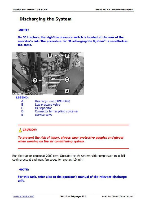
Discharging the System
Evacuating the System
Filling with Refrigerant Oil
Instructions for Starting Up the DENSO Air-Conditioning Compressor
Filling the System
Topping Up a Partly Discharged System
Leak Test
Removing the Compressor
Checking Level in the Compressor
Disassembling the Compressor Clutch
Checking Clutch Hub Clearance
Checking the Compressor Manifold
Installing the Compressor
Removing and Installing the Condenser
Removing and Installing the Receiver-Drier
Removing and Installing the Evaporator and Expansion Valvenot on SE tractors
Replacing the Expansion Valve
SE-Tractors: Removing and Installing the Evaporator and Expansion Valve
Installing Condensation Water Drain Hoses
SE-Tractors: Arrangement of Condensation Water Drain Hoses
Removing the Heater/Evaporator Housing From SE Tractors
Removing and Installing the Thermostat Switch
Adjusting Thermostat Switch Bowden Cables not on SE tractors
SE-Tractors: Removing and Installing the Thermostat Switch
Removing and Installing the High/Low Pressure Switch
Group 11: ClimaTrak
ClimaTrak - Summary of References
Removing and Installing the ATC Controller (ClimaTrak)
Removing and Installing the Driver Unit for Fan Motor (A59)
Removing and Installing the Sending Unit for Ambient Temperature (Front) (B125)
Removing and Installing the Sending Unit for Ambient Temperature (Rear) (B126)
Removing and Installing the Sending Unit for Inside Air Temperature (B127)
Removing and Installing the Sending Unit for Actual Outlet Air Temperature (B128)
Removing and Installing the Sending Unit for Evaporator Core Temperature (B129)
Removing and Installing Sending Unit for Refrigerant Pressure (B130)
Water Valve (B131) Removal and Installation
Mode Control for Position of Air Distribution Flaps (B132), Removal and Installation
Remove and Install the Defog sensor (B143)
Group 15: Heating System
Heating System (Summary of References)
6020 to 6620 Tractors
Adjusting Air Flow Bowden Cables
SE-Tractors
Group 20: Seats
Specifications
Super Comfort Seat MSG83
Comfort Seat MSG85
Air Comfort Seat MSG95A-00, Lower Section
Exploded View of the Instructional Seat
Command Arm Repair
Group 25: Operators's Cab
Operator's Cab (Summary of References)
Removing Cab Frame
Torques for Hardware on Platform Mounting (2-Post ROPS, Standard Version)
Cab Mounting Torques
Removing the Outer Roof
Removing and Installing the Windshield
Removing and Installing the Rear Window
Removal and Installation of Panoramic Windshield
Removing and Installing the Roof Hatch
Installing Door Lock
Adjusting Windshield and Rear Window Contact Pressure
Operator's Cab Door Removal and Installation
Roller Sun-Visor Removal and Installation
Removing Inner Roof Trim
Group 30: Cab Suspension
Cab Suspension - Summary of References
Important Instructions
Specifications
Relieving Hydraulic System Pressure
Installing and Removing the Cab Suspension Shields
Removing and Installing the Sensor Rod
Adjusting the Sensor Rod
Removing the Position Sensor
Reconditioning the Position Sensor
Installing the Position Sensor
Removing the Accumulator
Reconditioning the Accumulator
Installing the Accumulator
Removing Hydraulic Cylinder
Installing Hydraulic Cylinder
Removing the Control Valve Block
Reconditioning the Valves in the Control Valve Block
Installing the Control Valve Block
Panhard Link Removal and Installation
Bleeding Cab Suspension Hydraulic Cylinders
Section 99: Special Tools
Group 05: Special Tools (Dealer-Fabricated)
DFLX2 - Suspension Device
DFLX3 – Suspension Device for PowrQuad Module
DFLX13 - Holding Device
Suspension Eyes for Operator's Cab
DFLX14 – Suspended MFWD Axle Housing Bracket
Holding Tool
DFLX16 - Wooden Block
DFRW79 – Piston Holding Tool
DFLX22 – Socket Wrench Insert
DFLX24 - Seal Installer
DFLX25 – Driver
DFLX17 - Assembly and Guide Mandrels
Turning Device
Bushing
DFLX27 – Driver
DFLX23 – Socket Wrench Insert
Unlocking Device
DFLX21 - Special Wrench
Group 10: Special Tools (available from the dealer)
D01042AA – Load-Positioning Sling
D05007ST – Tractor Splitting Stand
JDE83 – Flywheel Turning Tool
JDG19 – Special Mounting Brackets
JDG23 – Lifting Sling
JDG749 - 1.30 m (52 in.) Torque Extension
JDG750 – Swivel Socket
JDG820 – Flywheel Turning Tool
JT05723 – Medium-Duty Rear Tractor Splitting Stand
JT05724 – Medium-Duty Front Tractor Splitting Stand
JT05725 – Universal Support Stand
JT02044 – Support Stand
KJD10293 – Disconnecting Tool
KJD10178C – Cab Tilting Device
KJD10173 – Shaft Puller
John Tractors 6020, 6020SE, 6120, 6120SE, 6220, 6220SE, 6320, 6320SE, 6420, 6420S, 6420SE, 6520, 6520SE, 6620 Repair Service Manual (TM4750)
![]()