
John Deere Tractors 6090MC, 6090RC, 6100MC, 6100RC, 6110MC, 6110RC Diagnosis and Tests Service Technical Manual (TM406519)
Complete Diagnosis & Tests Technical Manual with electrical wiring diagrams for 6090MC, 6090RC, 6100MC, 6100RC, 6110MC, 6110RC, with all the shop information to maintain, diagnose, and rebuild like professional mechanics.
John Deere European Tractors 6090MC, 6100MC, 6110MC, 6090RC, 6100RC, 6110RC (Worldwide Edition) workshop Diagnosis & Tests technical manual includes:
* Numbered table of contents easy to use so that you can find the information you need fast.
* Detailed sub-steps expand on repair procedure information
* Numbered instructions guide you through every repair procedure step by step.
* Troubleshooting and electrical service procedures are combined with detailed wiring diagrams for ease of use.
* Notes, cautions and warnings throughout each chapter pinpoint critical information.
* Bold figure number help you quickly match illustrations with instructions.
* Detailed illustrations, drawings and photos guide you through every procedure.
* Enlarged inset helps you identify and examine parts in detail.
tm406519 - 6090MC, 6100MC, 6110MC, 6090RC, 6100RC, 6110RC Tractors Diagnosis - (Worldwide Edition) Technical Manual.pdf
tm406519 - 6090MC, 6100MC, 6110MC, 6090RC, 6100RC, 6110RC Tractors Diagnosis - (Worldwide Edition) Technical Manual.epub
Total Pages: 5,416 pages
File Format: PDF/EPUB/MOBI/AZW (PC/Mac/Android/Kindle/iPhone/iPad; bookmarked, ToC, Searchable, Printable)
Language: English
MAIN SECTIONS
Foreword
General
Safety
General References
Diagnostic Trouble Codes
AIC Control Software
BLC Control Software
CCU Control Software
CRU Control Software
ECU Control Software
EIC Control Software
FCC Control Software
HCC Control Software
OIC Control Software
PDU Control Software
PTF Control Software
PTQ Control Software
RPT Control Software
SFA Control Software
SMB Control Software
TEC Control Software
TEI Control Software
TIQ Control Software
VTV Control Software
Observable Symptoms and System Diagnostics
Engine
Fuel, Air Intake, and Cooling Systems
Electrical System
Electronic Control Units
Drive Train (without Transmission)
PowrQuad™ Transmission
Steering
Brakes
Hydraulic System
Machine-Specific Systems
Suspension Systems
Operator's Cab
Engine
Exhaust Aftertreatment System, Theory of Operation
Tests and Adjustments
Fuel, Air Intake, and Cooling Systems
General Information
Fuel System, Theory of Operation
Air Intake System, Theory of Operation
Cooling System, Theory of Operation
Cold-Weather Starting System, Theory of Operation
Fuel, Air Intake, and Cooling Systems - Tests and Adjustments
Fuel, Air Intake, and Cooling Systems - Component Information
Fuel System, Component Information
Cooling System, Component Information
Charge Air Circuit, Component Information
Cold-Weather Starting System, Component Information
Electrical System
Summary of References
Operational schematics
50AA - Starter Motor and Charging Circuit
50AC - External Cold Start Aid
50BA - Lights
50BB - Flood Lights
50BC - Dome Light
50BD - Turn-Signal Lights
50CA - Operator's Seat
50CB - Acoustic Alarms
50CC - Windshield and Rear Window Wipers
50CD - Heater/Ventilation/Air-Conditioning System
50CE - Sockets
50CF - Radio
50CH - Accessories (General Information)
50EA - TEC Control Software and Implement CAN Bus
50FA - Electronic Engine Control
50FB - Immobilizer
50FC - Fuel System
50GA - PowrQuad™ Transmission
50GH - Differential Lock
50GI - Front-Wheel Drive
50GJ - Rear PTO
50GK - Front PTO
50GL - Brakes
50HA - Rear Hitch
50HD - Suspended Front-Wheel Drive Axle
50IA - Display
50JA - CAN Bus Systems
50X - Ground Connections
Electronic Control Units
Electronic Control Units - General Information
Electronic Control Units - Interactive Tests and Calibrations
Electronic Control Units - Information on Programming
Electronic Control Units - Theory of Operation
Electronic Control Units - Diagnostic Schematics
Electronic Control Units - Component Information
Electronic Control Units - Tests and Adjustments
Immobilizer Control Unit
AIC Control Software
BLC Control Software
CCU Control Software
ECU Control Software
EIC Control Software
FCC Control Software
HCC Control Software
OIC Control Software
PDU Control Software
PTF Control Software
PTQ Control Software
RPT Control Software
SFA Control Software
SMB Control Software
TEC Control Software
TEI Control Software
TIQ Control Software
VTV Control Software
Electrical Connectors, Wiring Harnesses and Components
Summary of Electrical Components and Harnesses
Electrical Components - Assemblies
Electrical Components - Sensors
Electrical Components - Various Devices and Equipment
Electrical Components - Protective Equipment
Electrical Components - Power Supply and Alternator
Electrical Components - Control and Signal Devices
Electrical Components - Relays
Electrical Components - Electrical Motors
Electrical Components - Resistors
Electrical Components - Switches
Electrical Components - Diodes
Electrical Components - Wiring Harnesses
Connector
Ground Points
Electrical Components - Solenoid Valves and Solenoids
Electrical Components - Other
Drive Train (without Transmission)
Drive Train (without Transmission) - Operational Checks
Drive Train (without Transmission) - Theory of Operation
Drive Train (without Transmission) - Tests and Adjustments
PowrQuad™ Transmission
PowrQuad™ Transmission - General Information
PowrQuad™ Transmission - Operational Checks
PowrQuad™ Transmission - Theory of Operation
PowrQuad™ Transmission - Schematics
PowrQuad™ Transmission - Tests and Adjustments
Drive Train - Component Information
Drive Train (without Transmission) - Component Information
PowrQuad™ Transmission - Component Information
Steering
Steering - General Information
Steering - Operational Checks
Steering - Theory of Operation
Steering - Schematics
Steering - Tests and Adjustments
Brakes
Brakes - General Information
Brakes - Operational Checks
Brakes - Theory of Operation
Brakes - Schematics
Brakes - Tests and Adjustments
Steering and Brakes - Component Information
Steering - Component Information
Brakes - Component Information
Hydraulic System
Hydraulic System - General Information
Hydraulic System - Operational Checks
Hydraulic System - Theory of Operation
Oil Filter, Additional Oil Reservoir, Charge Pump and Hydraulic Pump - Theory of Operation
Rear Hitch - Theory of Operation
Front Hitch - Theory of Operation
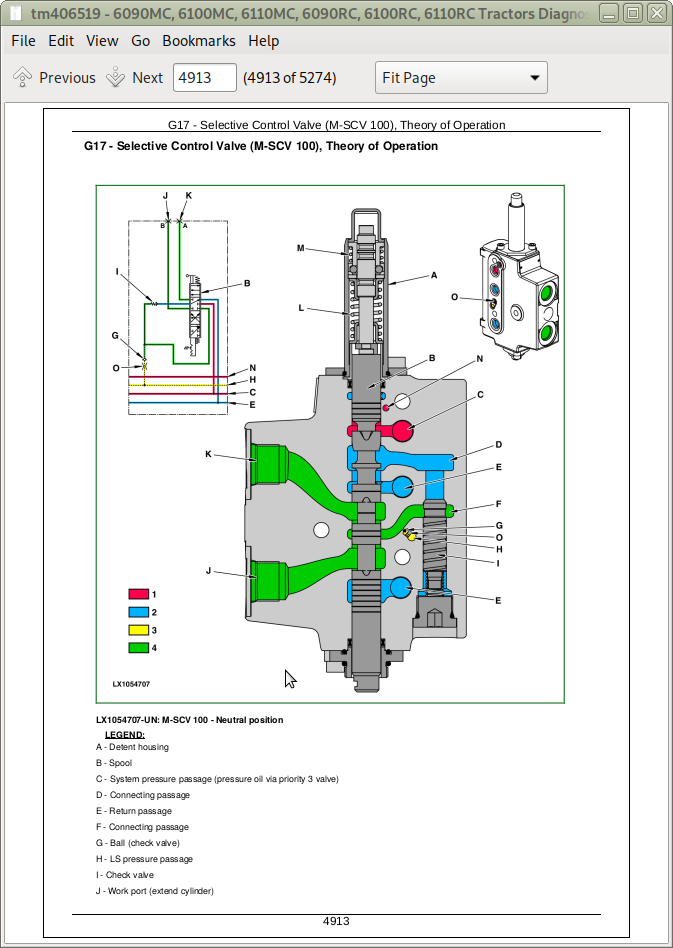
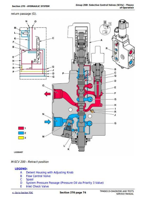
Selective Control Valves (SCVs) - Theory of Operation
Independent Control Valves (ICVs) - Theory of Operation
Hydraulic System - Schematics
Hydraulic System - Tests and Adjustments
Hydraulic System - Component Information
Hydraulic System - Component Information
Machine-Specific Systems
Machine-Specific Systems - Operational Checks
Machine-Specific Systems - Tests and Adjustments
Suspension Systems
Suspension Systems - Operational Checks
Suspended Front-Wheel Drive Axle - Theory of Operation
Suspended Front-Wheel Drive Axle - Schematics
Suspended Front-Wheel Drive Axle - Tests and Adjustments
Suspension Systems - Component Information
Suspended Front-Wheel Drive Axle - Component Information
Operator's Cab
Operator's Cab - Operational Checks
Operator's Cab - Theory of Operation
Operator's Cab - Tests and Adjustments
Operator's Cab - Component Information
Air Conditioning System - Component Information
Special Tools
General Information
tm406519 - 6090MC, 6100MC, 6110MC, 6090RC, 6100RC, 6110RC Tractors Diagnosis -: (Worldwide Edition)
Table of Contents
Foreword
Section 210: General Information
Group 05: Safety Measures
General Information - Safety - Summary of References
Recognize Safety Information
Understand Signal Words
Follow Safety Instructions
Prevent Machine Runaway
Operating the Tractor Safely
Operating the Loader Tractor Safely
Passenger Seat
Use Safety Lights and Devices
Towing Trailers/Implements Safely (Mass)
Use Caution On Slopes and Uneven Terrain
Freeing a Mired Machine
Avoid Backover Accidents
Handle Fluids Safely—Avoid Fires
Handling Batteries Safely
Prepare for Emergencies
Avoid High-Pressure Fluids
Service Cooling System Safely
Remove Paint Before Welding or Heating
Avoid Heating Near Pressurized Fluid Lines
Work In Ventilated Area
Avoid Contact with Agricultural Chemicals
Handle Agricultural Chemicals Safely
Stay Clear of Rotating Drivelines
Wear Protective Clothing
Protect Against Noise
Practice Safe Maintenance
Avoid Hot Exhaust
Exhaust Filter Cleaning
Clean Exhaust Filter Safely
Read Operator Manuals for ISOBUS Implements
Use Steps and Handholds Correctly
Use Seat Belt Properly
Park Machine Safely
Use Proper Lifting Equipment
Construct Dealer-Made Tools Safely
Support Machine Properly
Work in Clean Area
Illuminate Work Area Safely
Service Machines Safely
Service Accumulator Systems Safely
Service Tires Safely
Use Proper Tools
Service Front-Wheel Drive Tractor Safely
Avoid Eye Contact With Radar
Keep ROPS Installed Properly
Replace Safety Signs
Replace Safety Signs
Dispose of Waste Properly
Live With Safety
Safety Measures on Electronic Control Units
Servicing Electronic Control Units
Welding Near Electronic Control Units
Keep Electronic Control Unit Connectors Clean
Safety Instructions for Replacing a Halogen Bulb
Safety Instructions for Replacing Xenon (HID) Bulbs and Ballast Units
Group 10: General References
General Information - General References, Summary of References
Trademarks
Hydraulic Designators
Electrical Designators
General Information - Inch Bolt and Cap Screws, Torque Values
General Information - Metric Bolt and Cap Screws, Torque Values
General Information - Hydraulic System Inch Fittings, Torque Values
General Information - Hydraulic System Metric Fittings, Torque Values
General Information - Electrical System, Component Identification Table
General Information - Electrical System, How to Read a Diagnostic Schematic
General Information - Electrical System, Lead Numbers and Color Codes
General Information - Electrical System, Symbols in Schematic, Wiring and Harness Diagrams
General Information - Electrical System, Check the Connectors
General Information - Electrical System, Approach to Tabular Diagnostic Procedures
General Information - Electrical System, Troubleshooting Unsolved Problems
General Information - Electrical System, Worksheet for Circuit/Harness Test
General Information - Electrical System, Visual Check
General - Electrical System, Faults and Circuit Tests
General - Electrical System, Test for Open Circuit under Load
General Information - Electrical System, Seven-Step Test Procedure
General Information - Hydraulic System, Symbols in Circuit Diagrams
General - Regions and Country Versions
Section 211: Diagnostic Trouble Codes
Group AIC: AIC Control Software
AIC 000158.03 - Supply Voltage (ELX) Too High
AIC 000158.04 - Supply Voltage (ELX) Too Low
AIC 000168.03 - Supply Voltage Too High
AIC 000168.04 - Supply Voltage Too Low
AIC 000628.02 - Control Software Internal Fault
AIC 000628.12 - Control Software Internal Fault
AIC 000629.12 - Control Software Internal Fault
AIC 003509.03 - Sensor Supply Voltage #1 Too High
AIC 003509.04 - Sensor Supply Voltage #1 Too Low
AIC 003509.06 - Sensor Supply Voltage #1, Current Too High
AIC 003510.03 - Sensor Supply Voltage #2 Too High
AIC 003510.04 - Sensor Supply Voltage #2 Too Low
AIC 003510.06 - Sensor Supply Voltage #2, Current Too High
AIC 176865.02 - Remote Control Switch for Rear PTO, Malfunction
AIC 520257.02 - Auto Mode Switch Fault
AIC 520285.02 - Position Feedback Unit Fault
AIC 520285.03 - Position Feedback Unit Voltage Too High
AIC 520285.11 - Position Feedback Unit Fault
AIC 520286.02 - Quick Raise/Lower Switch Fault
AIC 520286.04 - Quick Raise/Lower Switch Voltage Too Low
AIC 520286.11 - Quick Raise/Lower Switch Fault
AIC 520602.02 - Switch for Gear Selector, Auto Mode and Clutch, Fault
AIC 520602.03 - Switch for Gear Selector, Auto Mode and Clutch, Voltage Too High
AIC 520602.04 - Switch for Gear Selector, Auto Mode and Clutch, Voltage Too Low
AIC 520602.11 - Switch for Gear Selector, Auto Mode and Clutch Out of Range
AIC 520870.02 - Configuration Data Fault, Internal Fault
AIC 520871.02 - Configuration Data Fault, Internal Fault
AIC 520872.02 - Configuration Data Fault, Internal Fault
AIC 522189.02 - iTEC™ Basic Switch Fault
AIC 522189.03 - iTEC™ Basic Switch Voltage Too High
AIC 522189.04 - iTEC™ Basic Switch Voltage Too Low
AIC 522189.11 - iTEC™ Basic Switch Fault
AIC 522546.02 - Switch for Gear Selector, Auto Mode and Clutch, Fault
AIC 522549.02 - Switch for Gear Selector, Auto Mode and Clutch, Fault
AIC 523343.02 - Additional Switch on Multi-Function Lever, Fault
AIC 523343.03 - Additional Switch on Multi-Function Lever, Voltage Too High
AIC 523343.04 - Additional Switch on Multi-Function Lever, Voltage Too Low
AIC 523670.02 - Speed Control Lever Voltage Out of Range
AIC 523670.11 - Speed Control Lever Fault
AIC 523671.07 - Right-Hand Reverser Fault
AIC 523671.13 - Right-Hand Reverser Not Calibrated
AIC 523745.02 - Switch for iTEC™ Basic Program Selection, Fault
AIC 523745.03 - iTEC™ Basic Switch Voltage Too High
AIC 523745.04 - iTEC™ Basic Switch Voltage Too Low
AIC 523745.11 - iTEC™ Basic Switch Fault
AIC 523775.02 - Multi-Function Lever (E-ICV), Fault
AIC 523776.02 - Transport Lock Switch (E-ICV), Fault
AIC 523776.11 - Transport Lock Switch (E-ICV), Fault
AIC 523804.02 - Multi-Function Lever (E-ICV), Left-Right Axis, Signal Out of Range
AIC 523804.03 - Multi-Function (E-ICV) Lever, Left-Right Axis, Voltage Too High
AIC 523804.04 - Multi-Function (E-ICV) Lever, Left-Right Axis, Voltage Too Low
AIC 523805.02 - Multi-Function Lever (E-ICV), Fore-Aft Axis, Signal Out of Range
AIC 523805.03 - Multi-Function Lever (E-ICV), Fore-Aft Axis, Voltage Too High
AIC 523805.04 - Multi-Function Lever (E-ICV), Fore-Aft Axis, Voltage Too Low
AIC 523953.02 - Sensor Unit for Speed Control Lever, Signal Out of Range
AIC 523953.03 - Sensor Unit for Speed Control Lever, Voltage Too High
AIC 523953.04 - Sensor Unit for Speed Control Lever, Voltage Too Low
AIC 523954.11 - Sensor Unit for Speed Control Lever (Speed Wheel), Output Signals do Not Match
AIC 523971.03 - Depth-Setting Potentiometer Voltage Too High
AIC 523971.04 - Depth-Setting Potentiometer Voltage Too Low
AIC 523971.13 - Depth-Setting Potentiometer Not Calibrated
AIC 524017.31 - Reverse Drive Lever Supply Voltage Faulty
AIC 524019.31 - Reverse Drive Lever, Faulty Signal from Neutral Switch
AIC 524020.31 - INFORMATION FOR OPERATOR: Reverse Drive Lever is in the Position for Forward or Reverse Travel During Start-up Procedure
AIC 524021.31 - Reverse Drive Lever Switches Actuated Simultaneously
AIC 524096.02 - Hand Throttle Potentiometer (AutoPowr™/IVT™ Transmission), Voltage Ratio Between Channel 1 and Channel 2 Not Correct
AIC 524096.03 - Hand Throttle Potentiometer Voltage Too High
AIC 524096.04 - Hand Throttle Potentiometer Voltage Too Low
AIC 524212.02 - Position Feedback Unit Faulty
AIC 524212.03 - Position Feedback Unit Voltage Too High
AIC 524212.04 - Position Feedback Unit Voltage Too Low
AIC 524212.11 - Quick Raise/Lower Switch Fault
AIC 524216.02 - Front PTO Switch Fault
AIC 524222.02 - APS Switch Faulty
AIC 524222.03 - APS Switch Voltage Too High
AIC 524222.04 - APS Switch Voltage Too Low
AIC 524222.11 - APS Switch Fault
AIC 524224.02 - Rear PTO Switch Fault
Group BLC: BLC Control Software
BLC 000628.02 - Control Software Internal Fault
BLC 000629.12 - Control Software Internal Fault
BLC 000630.02 - Control Software Internal Fault
BLC 000630.13 - Control Software Internal Fault
BLC 000630.31 - Control Software Internal Fault
BLC 000920.03 - Acoustic Alarm Voltage Too High
BLC 000920.06 - Acoustic Alarm Current Too High
BLC 001871.09 - Incorrect CAN BUS Message, Information from TEC Control Software
BLC 001871.19 - Incorrect CAN BUS Message, Implement Sends Error Message
BLC 001871.31 - CAN BUS Message Cannot Be Received, Information from Implement
BLC 001877.06 - Implement Switch, Current Too High
BLC 001877.09 - CAN BUS Message Cannot Be Received, Information from HCC Control Software
BLC 001877.19 - Hitch Control Fault
BLC 001877.31 - Hitch Control Fault
BLC 002000.09 - Incorrect CAN BUS Message, Information from ECU Control Unit
BLC 002007.09 - Incorrect CAN Bus Message, Information from RPT Control Software
BLC 002035.09 - Incorrect CAN BUS Message, Information from HCC Control Software
BLC 002036.09 - Incorrect CAN BUS Message, Information from PTF Control Software
BLC 002049.09 - Incorrect CAN Bus Message, Information from OIC Control Software
BLC 002050.06 - BLC Control Software Current Too High
BLC 002071.09 - Incorrect CAN BUS Message, Information from CCU Control Software
BLC 002140.09 - Incorrect CAN Bus Message, Information from AIC Control Software
BLC 002145.09 - Incorrect CAN BUS Message, Information from FCC Control Software
BLC 002240.09 - Incorrect CAN BUS Message, Information from TEC Control Software
BLC 002348.03 - High-Beam Headlights, External Voltage
BLC 002348.05 - High-Beam Headlights, Current Too Low
BLC 002348.06 - High-Beam Headlights, Current Too High
BLC 002350.03 - Low-Beam Headlights, External Voltage
BLC 002350.05 - Low-Beam Headlights, Current Too Low
BLC 002350.06 - Low-Beam Headlights, Current Too High
BLC 002352.03 - Low-Beam Headlights on Cab Frame, External Voltage
BLC 002352.05 - Low-Beam Headlights on Cab Frame, Current Too Low
BLC 002352.06 - Low-Beam Headlights on Cab Frame, Current Too High
BLC 002354.03 - Front Corner Worklights, External Voltage
BLC 002354.05 - Front Corner Worklights, Current Too Low
BLC 002354.06 - Front Corner Worklights, Current Too High
BLC 002358.03 - Worklights on Cab Frame or High-Beam Headlights on Cab Frame, External Voltage
BLC 002358.05 - Worklights on Cab Frame or High-Beam Headlights on Cab Frame, Current Too Low
BLC 002358.06 - Worklights on Cab Frame or High-Beam Headlights on Cab Frame, Current Too High
BLC 002360.03 - Worklight on Rear of Fender, External Voltage
BLC 002360.05 - Worklights on Rear Fenders, Current Too Low
BLC 002360.06 - Worklights on Rear Fenders, Current Too High
BLC 002362.03 - Inner Worklights on Rear of Roof, External Voltage
BLC 002362.05 - Inner Worklights on Rear of Roof, Current Too Low
BLC 002362.06 - Inner Worklights on Rear of Roof, Current Too High
BLC 002382.03 - Clearance Light, License Plate Light or Tail Light, External Voltage
BLC 002382.05 - Clearance Light, License Plate Light or Tail Light, Current Too Low
BLC 002382.06 - Clearance Light, License Plate Light or Tail Light, Current Too High
BLC 002396.03 - Inner Worklights on Front of Roof, External Voltage
BLC 002396.05 - Inner Worklights on Front of Roof, Current Too Low
BLC 002396.06 - Inner Worklights on Front of Roof, Current Too High
BLC 002398.03 - Outer Worklights on Front of Roof, External Voltage
BLC 002398.05 - Outer Worklights on Front of Roof, Current Too Low
BLC 002398.06 - Outer Worklights on Front of Roof, Current Too High
BLC 002407.03 - Outer Worklights on Rear of Roof, External Voltage
BLC 002407.05 - Outer Worklights on Rear of Roof, Current Too Low
BLC 002407.06 - Outer Worklights on Rear of Roof, Current Too High
BLC 520490.03 - Implement Voltage Supply, External Voltage
BLC 520490.06 - Implement Supply Voltage, Current Too High
BLC 520491.03 - Supply Voltage for a Control Unit on Implement, External Voltage
BLC 520491.06 - Supply Voltage for a Control Unit on Implement, Current Too High
BLC 522876.19 - Incorrect CAN BUS Message, Implement Sends Error Message
BLC 522876.31 - CAN BUS Message Cannot Be Received, Information from Implement
BLC 524259.00 - Main Control Unit Temperature Too High
BLC 524259.15 - Main Control Unit Temperature Too High
BLC 524259.16 - Main Control Unit Temperature Too High
Group CCU: CCU Control Software
CCU 000084.04 - Wheel Speed Sensor Voltage Too Low
CCU 000084.05 - Wheel Speed Sensor, Open Circuit
CCU 000096.03 - Fuel Level Sensor Voltage Too High
CCU 000096.04 - Fuel Level Sensor Voltage Too Low
CCU 000096.17 - INFORMATION FOR OPERATOR: Fuel Level Too Low
CCU 000126.16 - Transmission Oil Filter Restricted
CCU 000158.03 - Control Software, Supply Voltage (ELX) Too High
CCU 000158.04 - Control Software, Supply Voltage (ELX) Too Low
CCU 000177.00 - INFORMATION FOR OPERATOR: Transmission Oil Temperature Very High
CCU 000177.03 - Transmission Oil Temperature Sensor Voltage Too High
CCU 000177.04 - Transmission Oil Temperature Sensor Voltage Too Low
CCU 000177.16 - INFORMATION FOR OPERATOR: Transmission Oil Temperature High
CCU 000177.19 - Transmission Oil Temperature Sensor Fault
CCU 000190.09 - CAN BUS Message Cannot Be Received, Information from ECU Control Software
CCU 000190.19 - Engine Speed Sensor Fault
CCU 000190.31 - Engine Speed Sensor Fault
CCU 000191.09 - Incorrect CAN Bus Message, CAN Message from PTQ Control Software
CCU 000191.19 - Transmission Output Speed Fault
CCU 000191.31 - Transmission Output Speed Fault
CCU 000237.02 - VIN Information Mismatch
CCU 000237.14 - VIN Information, System Deactivated
CCU 000237.31 - VIN Information Incorrect
CCU 000247.09 - Incorrect CAN Bus Message, CAN Message from ECU Control Software
CCU 000247.19 - Operating Hours Fault
CCU 000247.31 - Operating Hours Fault
CCU 000628.02 - Control Software Internal Fault
CCU 000629.12 - Control Software Internal Fault
CCU 000630.14 - Control Software Internal Fault
CCU 000639.12 - Vehicle CAN Bus (500 kBd), High Error Rate
CCU 000639.14 - Vehicle CAN Bus (500 kBd), Very High Error Rate
CCU 000746.31 - Differential Lock Solenoid Valve Fault
CCU 001058.03 - Pressure Switch for Air Brake System, Voltage Too High
CCU 001058.04 - Pressure Switch for Air Brake System, Voltage Too Low
CCU 001058.16 - INFORMATION FOR OPERATOR: Pressure Switch for Air-Brake System Is Not Activated (Pressure Too High)
CCU 001058.18 - INFORMATION FOR OPERATOR: Pressure Switch for Air Brake System Is Not Active (Pressure Too Low)
CCU 001069.02 - INFORMATION FOR OPERATOR: Tire Circumference Not or Incorrectly Calibrated
CCU 001231.12 - Implement CAN Bus, High Error Rate
CCU 001231.14 - Implement CAN Bus, Very High Error Rate
CCU 001865.09 - Incorrect CAN Bus Message, Information from OIC Control Software
CCU 001865.19 - Incorrect CAN Bus Message, Information from OIC Control Software
CCU 002000.09 - Incorrect CAN Bus Message, Information from ECU Control Software
CCU 002003.09 - Incorrect CAN Bus Message, Information from PTQ Control Software
CCU 002005.09 - Incorrect CAN Bus Message, Information from TIQ Control Software
CCU 002049.09 - Incorrect CAN Bus Message, Information from OIC Control Software
CCU 002139.09 - Incorrect CAN Bus Message, Information from CSM Control Software
CCU 002145.09 - Incorrect CAN Bus Message, Information from FCC Control Software
CCU 002221.09 - Incorrect CAN Bus Message, Information from PLC Control Software
CCU 003510.03 - 5-Volt Supply Voltage, Voltage Too High
CCU 003510.04 - 5-Volt Supply Voltage, Voltage Too Low
CCU 003510.06 - 5-Volt Supply Voltage, Current Too High
CCU 520870.02 - Control Software Internal Fault
CCU 522580.09 - CAN Bus Message Cannot Be Received, Information from OIC Control Software
CCU 522580.19 - Front-Wheel Drive Switch, Fault
CCU 522580.31 - Front-Wheel Drive Switch, Fault
CCU 522763.09 - CAN Bus Message Cannot Be Received, Information from FCC Control Software
CCU 522763.19 - Reverse Drive Lever Fault
CCU 522763.31 - Reverse Drive Lever Fault
CCU 523652.02 - Main Control Unit Connected to Wrong Wiring Harness Connector
CCU 523666.03 - Control Software, Supply Voltage (BAT) Too High
CCU 523666.04 - Control Software, Supply Voltage (BAT) Too Low
CCU 523689.09 - Incorrect CAN Bus Message, CAN Message from OIC Control Software
CCU 523689.11 - Differential Lock Switch Fault
CCU 523689.19 - Differential Lock Switch Fault
CCU 523689.31 - Differential Lock Switch Fault
CCU 523769.31 - Front-Wheel Drive Switch, Fault
CCU 524157.09 - Incorrect CAN Bus Message, CAN Message from OIC Control Software
CCU 524157.19 - Right Brake Pedal Signal Fault
CCU 524157.31 - Right Brake Pedal Signal Fault
CCU 524162.09 - Incorrect CAN Bus Message, CAN Message from OIC Control Software
CCU 524162.19 - Left Brake Pedal Signal Fault
CCU 524162.31 - Left Brake Pedal Signal Fault
CCU 524191.02 - INFORMATION FOR OPERATOR: Air Brake System Fault
CCU 524191.03 - Air Brake System Solenoid Valve Voltage Too High
CCU 524191.05 - Air Brake System Solenoid Valve Voltage Too Low
CCU 524191.06 - Air Brake System Solenoid Valve Current Too High
CCU 524191.19 - INFORMATION FOR OPERATOR: Air Brake System Fault
CCU 524194.09 - Incorrect CAN Bus Message, CAN Message from PTQ Control Software
CCU 524194.19 - CAN Bus Message Regarding Direction of Travel, Fault
CCU 524194.31 - CAN Bus Message Regarding Direction of Travel, Fault
CCU 524218.09 - Incorrect CAN Bus Message, CAN Message from OIC Control Software
CCU 524218.19 - Park Lock Fault
CCU 524218.31 - Park Lock Fault
CCU 524235.02 - Front-Wheel Drive Fault
CCU 524235.31 - Front-Wheel Drive Solenoid Valve Fault
Group CRU: CRU Control Software
CRU 000168.03 - Control Software, Supply Voltage (BAT) Too High
CRU 000168.04 - Control Software, Supply Voltage (BAT) Too Low
CRU 000237.02 - VIN Information, Mismatch
CRU 000639.12 - Vehicle CAN Bus (500 kBd), High Error Rate
CRU 520194.02 - VIN Information, Mismatch
CRU 520772.12 - Control Software, Internal Fault
CRU 521156.12 - XM Satellite Radio, Fault
CRU 521780.06 - USB Connection, Current Too High
CRU 522453.12 - Control Software, Internal Fault
CRU 524259.00 - CD Drive, Temperature Too High
CRU 524259.31 - Radio, Temperature Too High
Group ECU: ECU Control Software
ECU 000027.03 - EGR Valve Position Signal Out of Range High
ECU 000027.04 - EGR Valve Position Signal Out of Range Low
ECU 000027.07 - EGR Valve Desired and Actual Position Mismatch
ECU 000084.31 - Wheel Speed Sensor, Fault
ECU 000094.03 - Low-Pressure Fuel Signal Out of Range High
ECU 000094.04 - Low-Pressure Fuel Signal Out of Range Low
ECU 000094.16 - Low-Pressure Fuel Signal Moderately High
ECU 000094.17 - Low-Pressure Fuel Signal Slightly Low
ECU 000094.18 - Low-Pressure Fuel Signal Moderately Low
ECU 000097.00 - Water-In-Fuel Level Extremely High
ECU 000097.03 - Water-In-Fuel Signal Voltage Out of Range High
ECU 000097.04 - Water-In-Fuel Signal Out Of Range Low
ECU 000097.16 - Water-In-Fuel Level Moderately High
ECU 000100.01 - Engine Oil Pressure Signal Extremely Low
ECU 000100.02 - Engine Oil Pressure is not Zero with Engine Stopped
ECU 000100.03 - Engine Oil Pressure Signal Out of Range High
ECU 000100.04 - Engine Oil Pressure Signal Out of Range Low
ECU 000100.18 - Engine Oil Pressure Signal Moderately Low
ECU 000101.00 - Crankcase Pressure Signal Extremely High
ECU 000101.03 - Crankcase Pressure Signal Out of Range High
ECU 000101.04 - Crankcase Pressure Signal Out of Range Low
ECU 000101.06 - Crankcase Pressure Signal Out of Range High
ECU 000101.16 - Engine Crankcase Pressure Moderately High
ECU 000102.00 - Manifold Air Pressure Signal Extremely High
ECU 000102.03 - Manifold Air Pressure Signal Out of Range High
ECU 000102.04 - Manifold Air Pressure Signal Out of Range Low
ECU 000102.07 - Manifold Air Pressure Signal In Range Invalid
ECU 000102.16 - Manifold Air Pressure Signal Moderately High
ECU 000105.00 - Manifold Temperature Signal Extremely High
ECU 000105.03 - Manifold Temperature Signal Out of Range High
ECU 000105.04 - Manifold Temperature Signal Out of Range Low
ECU 000105.15 - Manifold Temperature Signal Slightly High
ECU 000105.16 - Manifold Temperature Signal Moderately High
ECU 000107.00 - Air Cleaner Pressure Differential Extremely High
ECU 000107.15 - Air Cleaner Pressure Differential Slightly High
ECU 000107.16 - Air Cleaner Pressure Differential Moderately High
ECU 000107.31 - Air Filter Pressure Differential Incorrect
ECU 000108.02 - Barometric Pressure Signal Invalid
ECU 000108.07 - Barometric Pressure Signal Mismatch
ECU 000110.00 - Engine Coolant Temperature Signal Extremely High
ECU 000110.03 - Engine Coolant Temperature Signal Out of Range High
ECU 000110.04 - Engine Coolant Temperature Signal Out of Range Low
ECU 000110.15 - Engine Coolant Temperature Signal Slightly High
ECU 000110.16 - Engine Coolant Temperature Signal Moderately High
ECU 000110.17 - Engine Coolant Temperature Signal Slightly Low
ECU 000152.12 - Control Software, Internal Fault
ECU 000152.14 - Control Software, Internal Fault
ECU 000152.16 - Control Software, Internal Fault
ECU 000157.01 - Fuel Rail Pressure Signal Extremely Low
ECU 000157.03 - Fuel Rail Pressure Signal Out of Range High
ECU 000157.04 - Fuel Rail Pressure Signal Out of Range Low
ECU 000157.16 - Fuel Rail Pressure Signal Moderately High
ECU 000157.17 - Fuel Rail Pressure Signal Slightly Low
ECU 000157.18 - Fuel Rail Pressure Signal Moderately Low
ECU 000158.01 - ECU, Supply Voltage (ELX) Extremely Low
ECU 000158.04 - ECU, Supply Voltage (ELX) Too Low
ECU 000158.12 - Engine Control Unit Power Down Error
ECU 000158.17 - Engine Control Unit, Internal Voltage Incorrect
ECU 000158.31 - Ignition Switch, Fault
ECU 000160.02 - Wheel Speed Sensor Signal Invalid
ECU 000168.01 - Unswitched Battery Voltage Extremely Low
ECU 000168.16 - Unswitched Battery Voltage Moderately High
ECU 000168.17 - Unswitched Battery Power Too Low (Engine Speed above 1500 rpm)
ECU 000168.18 - Unswitched Battery Voltage Moderately Low
ECU 000174.00 - Fuel Temperature Signal Extremely High
ECU 000174.03 - Fuel Temperature Signal Out of Range High
ECU 000174.04 - Fuel Temperature Signal Out of Range Low
ECU 000174.16 - Fuel Temperature Signal Moderately High
ECU 000189.00 - Engine Speed Derate Condition Exists
ECU 000189.31 - Engine Speed Derate Condition Exists
ECU 000190.00 - Engine Speed Extremely High
ECU 000190.16 - Engine Speed Moderately High
ECU 000237.02 - VIN Information, Mismatch
ECU 000237.13 - VIN Information, Option Code Invalid
ECU 000237.31 - VIN Information, Incorrect
ECU 000412.00 - EGR Temperature Signal Extremely High
ECU 000412.03 - EGR Temperature Signal Out of Range High
ECU 000412.04 - EGR Temperature Signal Out of Range Low
ECU 000412.15 - EGR Temperature Signal Slightly High
ECU 000412.16 - EGR Temperature Signal Moderately High
ECU 000611.03 - Injector Drive #1 Shorted to Voltage Source
ECU 000611.04 - Injector Drive #1 Shorted to Ground
ECU 000612.03 - Injector Drive #2 Shorted to Voltage Source
ECU 000612.04 - Injector Drive #2 Shorted to Ground
ECU 000628.12 - Control Software, Internal Fault
ECU 000629.11 - ECU Binary Input Error
ECU 000629.12 - ECU EEPROM Error
ECU 000629.13 - ECU Boot Block Error
ECU 000636.02 - Camshaft Speed Signal Invalid
ECU 000636.05 - Camshaft Position Sensor Circuit Has High Resistance
ECU 000636.06 - Camshaft Position Sensor Circuit Has Low Resistance
ECU 000636.08 - Camshaft Speed Signal Missing
ECU 000636.10 - Camshaft Speed Signal Rate of Change Abnormal
ECU 000637.02 - Crankshaft Speed Signal Invalid
ECU 000637.05 - High Resistance in Crankshaft Speed Circuit
ECU 000637.06 - Low Resistance in Crankshaft Speed Circuit
ECU 000637.07 - Camshaft Speed and Crankshaft Speed Signals Out of Sync
ECU 000637.08 - Crankshaft Speed Signal Missing
ECU 000637.10 - Crankshaft Position Signal Rate of Change Abnormal
ECU 000641.00 - Exhaust Throttle Actuator Temperature Extremely High
ECU 000641.05 - High Resistance in Exhaust Throttle Actuator Drive Circuit
ECU 000641.06 - Low Resistance in Exhaust Throttle Actuator Drive Circuit
ECU 000641.07 - VGT Actuator Learn Error
ECU 000641.09 - Exhaust Throttle Actuator Loss of Communication
ECU 000641.12 - Exhaust Throttle Actuator Internal Error
ECU 000641.13 - Exhaust Throttle Actuator Calibration Error
ECU 000641.16 - Exhaust Throttle Actuator Temperature Slightly High
ECU 000641.31 - Exhaust Throttle Actuator Supply Voltage Fault
ECU 000651.00 - Maximum Pulse Duration of Injector #1 Incorrect
ECU 000651.01 - Minimum Pulse Duration of Injector #1 Incorrect
ECU 000651.02 - Injector #1 Part Number Data Invalid
ECU 000651.05 - Injector #1 Circuit Has High Resistance
ECU 000651.06 - Injector #1 Circuit Has Low Resistance
ECU 000651.13 - Injector #1 Calibration Fault
ECU 000651.18 - Injector #1 Not Responding
ECU 000652.00 - Maximum Pulse Duration of Injector #2 Incorrect
ECU 000652.01 - Minimum Pulse Duration of Injector #2 Incorrect
ECU 000652.02 - Injector #2 Part Number Data Invalid
ECU 000652.05 - Injector #2 Circuit Has High Resistance
ECU 000652.06 - Injector #2 Circuit Has Low Resistance
ECU 000652.13 - Injector #2 Calibration Fault
ECU 000652.18 - Injector #2 Not Responding
ECU 000653.00 - Maximum Pulse Duration of Injector #3 Incorrect
ECU 000653.01 - Minimum Pulse Duration of Injector #3 Incorrect
ECU 000653.02 - Injector #3 Part Number Data Invalid
ECU 000653.05 - Injector #3 Circuit Has High Resistance
ECU 000653.06 - Injector #3 Circuit Has Low Resistance
ECU 000653.13 - Injector #3 Calibration Fault
ECU 000653.18 - Injector #3 Not Responding
ECU 000654.00 - Maximum Pulse Duration of Injector #4 Incorrect
ECU 000654.01 - Minimum Pulse Duration of Injector #4 Incorrect
ECU 000654.02 - Injector #4 Part Number Data Invalid
ECU 000654.05 - Injector #4 Circuit Has High Resistance
ECU 000654.06 - Injector #4 Circuit Has Low Resistance
ECU 000654.13 - Injector #4 Calibration Fault
ECU 000654.18 - Injector #4 Not Responding
ECU 000676.03 - Relay for Electric Starting Aid, Current Too High
ECU 000676.05 - Relay for Electric Starting Aid, Current Too Low
ECU 000676.06 - Cold Start Aid Drive Circuit Has Low Resistance
ECU 000676.14 - Cold Start Aid Relay Signal Not Received When Expected
ECU 000676.31 - Cold Start Aid Relay Signal Received When Not Expected
ECU 000695.19 - Unapproved Engine Speed Request
ECU 000970.31 - Engine Start Fault
ECU 000971.31 - External Derate Commanded
ECU 001110.31 - Engine Protection Shutdown
ECU 001069.31 - Tire Size Error
ECU 001136.00 - ECU Temperature Signal Extremely High
ECU 001136.02 - ECU Temperature Signal Invalid
ECU 001136.16 - ECU Temperature Signal Moderately High
ECU 001172.12 - Intake Air Temperature Error
ECU 001176.07 - Intake Air Pressure Mismatch
ECU 001176.12 - Intake Air Pressure Error
ECU 001180.00 - Calculated VGT Turbine Inlet Temperature Extremely High
ECU 001180.16 - Calculated VGT Turbine Inlet Temperature Moderately High
ECU 001209.03 - Exhaust Manifold Pressure Signal Out of Range High
ECU 001209.04 - Exhaust Manifold Pressure Signal Out of Range Low
ECU 001209.07 - Exhaust Manifold Pressure Mismatch
ECU 001321.05 - Engine Starter Solenoid Lockout Relay Circuit Has High Resistance
ECU 001321.06 - Engine Starter Solenoid Lockout Relay Circuit Has Low Resistance
ECU 001321.16 - Engine Starter Engaged for Too Long
ECU 001321.31 - Engine Speed Zero with Starter Solenoid Energized
ECU 001322.31 - Engine Misfires Detected
ECU 001347.01 - Suction Control Valve Sticking and Fuel Rail Pressure Extremely Low
ECU 001347.03 - High Voltage in Circuit of Suction Control Valve
ECU 001347.05 - Suction Control Valve Circuit Has High Resistance
ECU 001347.06 - Suction Control Valve Circuit Has Low Resistance
ECU 001347.07 - Fuel Pressure of Suction Control Valve Deviates
ECU 001347.16 - Suction Control Valve Sticking and Fuel Rail Pressure Moderately High
ECU 001347.18 - Suction Control Valve Sticking and Fuel Rail Pressure Slightly Low
ECU 001569.31 - Engine in Derate Condition
ECU 002003.09 - Incorrect CAN BUS Message, Information from PTQ Control Software
ECU 002006.09 - Incorrect CAN Bus Message, Information from EIC Control Software
ECU 002006.14 - Control Software, Internal Fault
ECU 002006.19 - Control Software, Internal Fault
ECU 002040.09 - Incorrect CAN Bus Message, Information from EIC Control Software
ECU 002071.09 - Incorrect CAN BUS Message, Information from CCU Control Software
ECU 002630.00 - Charge Air Cooler Outlet Temperature Signal Extremely High
ECU 002630.03 - Charge Air Cooler Outlet Temperature Signal Out of Range High
ECU 002630.04 - Charge Air Cooler Outlet Temperature Signal Out of Range Low
ECU 002630.15 - Charge Air Cooler Outlet Temperature Signal Slightly High
ECU 002630.16 - Charge Air Cooler Outlet Temperature Signal Moderately High
ECU 002790.16 - Calculated Outlet Temperature Moderately High
ECU 002791.05 - EGR Valve Drive Circuit Fault
ECU 002791.06 - EGR Valve Drive Circuit Has Low Resistance
ECU 002791.07 - EGR Valve Desired and Actual Position Mismatch During a Learn
ECU 002791.13 - EGR Valve Calibration Error
ECU 002795.07 - Exhaust Throttle Desired and Actual Position Mismatch
ECU 002795.31 - VGT Actuator Fault
ECU 002797.03 - Injector High Voltage Supply #1 Out of Range High
ECU 002797.05 - Injector High Voltage Supply #1 Circuit Has High Resistance
ECU 002797.06 - Injector High Voltage Supply #1 Circuit Has Low Resistance
ECU 002798.03 - Injector High Voltage Supply #2 Out of Range High
ECU 002798.05 - Injector High Voltage Supply #2 Circuit Has High Resistance
ECU 002798.06 - Injector High Voltage Supply #2 Circuit Has Low Resistance
ECU 003246.00 - DPF Outlet Temperature Extremely High
ECU 003246.12 - DPF Outlet Temperature Error
ECU 003251.00 - DPF Differential Pressure Signal Not Responding
ECU 003251.02 - DPF Differential Pressure Signal Invalid
ECU 003251.03 - DPF Differential Pressure Signal Out of Range High
ECU 003251.04 - DPF Differential Pressure Signal Out of Range Low
ECU 003251.07 - DPF Differential Pressure Signal Mismatch
ECU 003353.31 - Alternator, Fault
ECU 003465.00 - Exhaust Throttle Actuator Temperature Extremely High
ECU 003465.05 - Exhaust Throttle Actuator Drive Circuit Has High Resistance
ECU 003465.06 - Exhaust Throttle Actuator Drive Circuit Has Low Resistance
ECU 003465.07 - Exhaust Throttle Actuator Learn Error
ECU 003465.09 - Exhaust Throttle Actuator Loss of Communication
ECU 003465.12 - Exhaust Throttle Actuator Internal Error
ECU 003465.13 - Exhaust Throttle Actuator Calibration Error
ECU 003465.16 - Exhaust Throttle Actuator Temperature Moderately High
ECU 003465.31 - Exhaust Throttle Actuator Supply Voltage Fault
ECU 003509.03 - Sensor Supply #1 Voltage Out of Range High
ECU 003509.04 - Sensor Supply #1 Voltage Out of Range Low
ECU 003510.03 - Sensor Supply #2 Voltage Out of Range High
ECU 003510.04 - Sensor Supply #2 Voltage Out of Range Low
ECU 003511.03 - Sensor Supply Voltage 3 Out of Range High
ECU 003511.04 - Sensor Supply Voltage 3 Out of Range Low
ECU 003512.03 - Sensor Supply #4 Voltage Out of Range High
ECU 003512.04 - Sensor Supply #4 Voltage Out of Range Low
ECU 003513.03 - Sensor Supply #5 Voltage Out of Range High
ECU 003514.03 - Sensor Supply #6 Voltage Out of Range High
ECU 003514.04 - Sensor Supply #6 Voltage Out of Range Low
ECU 003597.01 - Injector High Voltage Supply Extremely Low
ECU 003673.31 - Exhaust Throttle Actuator Desired and Actual Position Mismatch
ECU 003711.14 - Regeneration Not Possible, Exhaust Temperature Fault
ECU 003711.31 - Regeneration Not Possible, Exhaust Temperature Too Low
ECU 003719.00 - Calculated Soot Level Extremely High
ECU 003719.10 - Calculated Soot Loading Rate of Change Abnormal
ECU 003719.13 - Excessive DPF Recovery Attempts
ECU 003719.14 - Calculated Soot Level Extremely High
ECU 003719.15 - Calculated Soot Level Slightly High
ECU 003719.16 - Calculated Soot Level Moderately High
ECU 003720.15 - Calculated Ash Level Slightly High
ECU 003720.16 - Calculated Ash Level Moderately High
ECU 003936.00 - Calculated Unintended Combustibles in DPF Extremely High
ECU 003936.15 - Calculated Unintended Combustibles in DPF Slightly High
ECU 003936.16 - Calculated Unintended Combustible In DPF Moderately High
ECU 004490.12 - Intake Air Humidity Error
ECU 004765.00 - DOC Inlet Temperature Extremely High
ECU 004765.12 - DOC Inlet Temperature Error
ECU 004766.12 - DOC Outlet Temperature Error
ECU 004766.16 - DOC Outlet Temperature Moderately High
ECU 004766.17 - DOC Outlet Temperature Slightly Low
ECU 004766.18 - DOC Outlet Temperature Moderately Low
ECU 004795.13 - Exhaust Filter Calibration Fault
ECU 004795.31 - DPF Missing
ECU 005018.00 - Calculated Unintended Combustibles in DOC Extremely High
ECU 005018.15 - Calculated Unintended Combustibles in DOC Slightly High
ECU 005018.16 - Calculated Unintended Combustibles in DOC Moderately High
ECU 005125.03 - Sensor Supply #7 Voltage Out of Range High
ECU 005125.04 - Sensor Supply #7 Voltage Out of Range Low
ECU 005126.03 - Sensor Supply #8 Voltage Out of Range High
ECU 005126.04 - Sensor Supply #8 Voltage Out of Range Low
ECU 005127.03 - Sensor Supply #9 Voltage Out of Range High
ECU 005127.04 - Sensor Supply #9 Voltage Out of Range Low
ECU 005298.01 - DOC Efficiency Extremely Low
ECU 005298.18 - DOC Efficiency Moderately Low
ECU 055010.31 - Illegal ECU Structure
ECU 520629.31 - Control Software, Internal Fault
ECU 520956.05 - Relay for Battery Cut-Off Relay, Current Too Low
ECU 520956.06 - Relay for Battery Cut-Off Relay, Current Too High
ECU 521192.11 - Engine Shutdown, Time-Out
ECU 521214.09 - Incorrect CAN Bus Message, Information from EIC Control Software
ECU 521214.14 - VIN Information, Mismatch
ECU 522494.09 - Intake Air Sensor Communication Error
ECU 522495.09 - Exhaust Filter Temperature Module Loss of Communication
Group EIC: EIC Control Software
EIC 000628.02 - Control software internal fault
EIC 000628.12 - Control Software, Internal Fault
EIC 000630.13 - Control Software, Internal Fault
EIC 001237.31 - Immobilizer key identification fault
EIC 002000.09 - Incorrect CAN BUS message, Information from ECU control software
EIC 002007.09 - Incorrect CAN BUS message, Information from RPT control software
EIC 002029.09 - Incorrect CAN BUS message, Information from immobilizer control unit
EIC 002029.12 - Immobilizer Control Unit Information Error
EIC 002140.09 - Incorrect CAN BUS message, Information from AIC control software
EIC 003695.14 - Automatic exhaust filter cleaning deactivated
EIC 003719.15 - Automatic exhaust filter cleaning not completed
EIC 003719.16 - Calculated Soot Level Extremely High
EIC 521192.12 - VIN information, Mismatch
EIC 521192.13 - VIN information, Mismatch
EIC 521214.11 - Immobilizer, Malfunction
EIC 521214.31 - Memory information invalid
EIC 521321.09 - Incorrect CAN BUS message, Information from immobilizer
EIC 521321.12 - Immobilizer key unknown
EIC 521322.07 - Faulty immobilizer antenna
EIC 521322.31 - Immobilizer key chip fault
EIC 523702.14 - VIN information, Mismatch
EIC 523702.31 - Memory information invalid
Group FCC: FCC Control Software
FCC 000158.00 - Instrument Unit, Supply Voltage (ELX) Too High
FCC 000158.01 - Instrument Unit, Supply Voltage (ELX) Too Low
FCC 000158.17 - Instrument Unit, Supply Voltage (ELX) Too Low
FCC 000158.18 - Instrument Unit, Supply Voltage (ELX) Too Low
FCC 000168.18 - Instrument Unit, Supply Voltage (BAT) Too Low
FCC 000237.02 - VIN Information, Mismatch
FCC 000237.14 - VIN Information, System Disabled
FCC 000237.31 - VIN Information, Incorrect
FCC 000444.03 - Control Software, Supply Voltage (BAT) Too High
FCC 000444.04 - Control Software, Supply Voltage (BAT) Too Low
FCC 000628.02 - Control software internal fault
FCC 000629.12 - Control software internal fault
FCC 000630.02 - Control software internal fault
FCC 000630.12 - Control software internal fault
FCC 000639.12 - 500 kBd vehicle CAN BUS, high error rate
FCC 000639.14 - CAN BUS - vehicle (500 kBd), Very high error rate
FCC 002003.09 - Incorrect CAN Bus Message, Information from PTQ Control Software
FCC 002005.09 - Incorrect CAN BUS message, Information from TIQ control software
FCC 002145.06 - Control Software FCC, Current Too High
FCC 002368.05 - Left Turn-Signal Light on Implement, Current Too Low
FCC 002368.06 - Left Turn-Signal Light on Implement, Current Too High
FCC 002370.05 - Right Turn-Signal Light on Implement, Current Too Low
FCC 002370.06 - Right Turn-Signal Light on Implement, Current Too High
FCC 002825.13 - Incorrect CAN BUS message, Information from PTQ control software
FCC 002825.31 - Forward/reverse lever, Malfunction
FCC 002826.31 - Forward/reverse lever, Malfunction
FCC 002828.31 - Reverse drive lever, power-zero switch, move switch and either the forward or reverse switch are activated simultaneously for too long a period.
FCC 002829.31 - Reverse drive lever, park lock switch, and neutral switch or power zero switch are activated simultaneously for too long a period
FCC 002863.02 - Switch for windshield and rear window wipers, Fault at windshield
FCC 002865.02 - Switch for windshield and rear window wipers, Malfunction at rear window
FCC 002872.02 - Light Switch, Fault
FCC 002876.02 - Turn-Signal Lever, Fault
FCC 003353.31 - Alternator, Fault
FCC 520917.05 - Left Turn-Signal Light, Current Too Low
FCC 520917.06 - Left Turn-Signal Light, Current Too High
FCC 520918.05 - Right Turn-Signal Light, Current Too Low
FCC 520918.06 - Right Turn-Signal Light, Current Too High
FCC 522122.31 - Incorrect CAN BUS message, Information from PTA or PTQ control software
FCC 522123.31 - Incorrect CAN BUS message, Information from PTA or PTQ control software
FCC 522124.31 - Incorrect CAN BUS message, Information from PTA or PTQ control software
FCC 522125.31 - Incorrect CAN BUS message, Information from PTA or PTQ control software
FCC 522358.31 - Incorrect CAN BUS message, Information from PTA or PTQ control software
FCC 524020.31 - INFORMATION FOR OPERATOR: Forward/reverse lever not in neutral position during start-up
FCC 524022.31 - Forward/reverse lever, Malfunction
FCC 524264.02 - Incorrect CAN BUS message, Information from PTQ control software
Group HCC: HCC Control Software
HCC 000158.03 - Control Software, Supply Voltage (ELX) Too High
HCC 000158.04 - Control Software, Supply Voltage (ELX) Too Low
HCC 000168.03 - Control Software, Supply Voltage (BAT) Too High
HCC 000168.04 - Control Software, Supply Voltage (BAT) Too Low
HCC 000190.02 - INFORMATION FOR OPERATOR: Engine speed too low during the calibration
HCC 000444.03 - Control Software, Supply Voltage (BAT on Pin J4) Too High
HCC 000444.04 - Control Software, Supply Voltage (BAT on Pin J4) Too Low
HCC 000629.12 - Control Software, Internal Error
HCC 000630.13 - Control Software Not or Incorrectly Calibrated
HCC 000639.14 - Vehicle CAN Bus (500 kBd), Very High Error Rate
HCC 001638.02 - INFORMATION FOR OPERATOR: Transmission Oil Temperature Too Low During Calibration
HCC 001873.03 - Hitch Position Sensor, Voltage Too High
HCC 001873.04 - Hitch Position Sensor, Voltage Too Low
HCC 001873.11 - Hitch position sensor, Metering range too small
HCC 001873.13 - Hitch position sensor not or incorrectly calibrated
HCC 001873.31 - Hitch Position Sensor, Fault
HCC 001881.03 - Draft Sensor, Voltage Too High
HCC 001881.04 - Draft Sensor, Voltage Too Low
HCC 001881.13 - Draft Sensor Out of Range
HCC 002049.09 - Incorrect CAN Bus Message, Information from OIC Control Software
HCC 002071.09 - Incorrect CAN BUS Message, Information from CCU Control Software
HCC 002139.09 - Incorrect CAN BUS Message, Information from CSM Control Software
HCC 002140.09 - Incorrect CAN Bus Message, Information from AIC Control Software
HCC 002152.09 - Incorrect CAN Bus Message, Information from HV1 Control Software
HCC 002602.18 - INFORMATION FOR OPERATOR: Low transmission oil level
HCC 003509.03 - 5-volt supply voltage, Voltage too high
HCC 003509.04 - 5-volt supply voltage, Voltage too low
HCC 003509.06 - 5-volt supply voltage, Current too high
HCC 520870.02 - Control Software, Internal Fault
HCC 520871.02 - Control Software, Internal Fault
HCC 521000.02 - Switch for Hitch Remote Control (Right/Left), Fault
HCC 521000.09 - Incorrect CAN Bus Message, Information from Switch for Hitch Remote Control (Right/Left) from OIC Control Software
HCC 521000.31 - Switch for Hitch Remote Control (Right/Left), Fault
HCC 521001.02 - Stepper Motor for Hitch (Raise Valve), Disrupted Signal during Calibration
HCC 521001.03 - Stepper Motor for Hitch (Raise Valve), Voltage Too High
HCC 521001.04 - Stepper Motor for Hitch (Raise Valve), Voltage Too Low
HCC 521001.05 - Stepper Motor for Hitch (Raise Valve), Current Too Low
HCC 521001.06 - Stepper Motor for Hitch (Raise Valve), Current Too High
HCC 521001.07 - Stepper Motor for Hitch (Raise Valve), Fault
HCC 521001.11 - Stepper Motor for Hitch (Raise Valve), Fault
HCC 521001.13 - Stepper Motor for Hitch (Raise Valve) Not Calibrated
HCC 521002.02 - Stepper Motor for Hitch (Lower Valve), Disrupted Signal during Calibration
HCC 521002.03 - Stepper Motor for Hitch (Lower Valve), Voltage Too High
HCC 521002.04 - Stepper Motor for Hitch (Lower Valve), Voltage Too Low
HCC 521002.05 - Stepper Motor for Hitch (Lower Valve), Current Too Low
HCC 521002.06 - Stepper Motor for Hitch (Lower Valve), Current Too High
HCC 521002.07 - Stepper Motor for Hitch (Lower Valve), Fault
HCC 521002.11 - Stepper Motor for Hitch (Lower Valve), Fault
HCC 521002.13 - Stepper Motor for Hitch (Lower Valve) Not Calibrated
HCC 522390.09 - Incorrect CAN Bus Message, Information from Implement
HCC 522390.11 - Tractor-Implement Automation™, Fault
HCC 523652.02 - Control Unit Connected to Wrong Wiring Harness Connector
HCC 523701.05 - Stepper Motor for Hitch (Coil 1), Open Circuit
HCC 523701.06 - Stepper Motor for Hitch (Coil 1), Current Too High
HCC 523703.03 - Draft Sensor (Right), Voltage Too High
HCC 523703.04 - Draft Sensor (Right), Voltage Too Low
HCC 523703.13 - Draft Sensor (Right) Out of Range
HCC 523714.31 - Solenoid Valve for Draft Link Stabilizer (No-Float Position), Fault
HCC 523715.31 - Solenoid Valve for Draft Link Stabilizer (Float Position), Fault
HCC 523751.05 - Stepper Motor for Hitch (Coil 2), Open Circuit
HCC 523751.06 - Stepper Motor for Hitch (Coil 2), Current Too High
HCC 523832.03 - Rate-of-Drop Potentiometer, Voltage Too High
HCC 523832.04 - Rate-of-Drop Potentiometer, Voltage Too Low
HCC 523832.13 - Rate-of-Drop Potentiometer, Out of Range
HCC 523833.03 - Raise Limit Potentiometer, Voltage Too High
HCC 523833.04 - Raise Limit Potentiometer, Voltage Too Low
HCC 523833.13 - Raise Limit Potentiometer, Out of Range
HCC 523834.03 - Depth-Setting Potentiometer, Voltage Too High
HCC 523834.04 - Depth-Setting Potentiometer, Voltage Too Low
HCC 523834.13 - Depth-Setting Potentiometer Not Calibrated
HCC 523834.31 - Depth-setting potentiometer, Malfunction
HCC 523842.03 - Sensitivity Potentiometer of Rear Hitch, Voltage Too High
HCC 523842.04 - Sensitivity Potentiometer of Rear Hitch, Voltage Too Low
HCC 523842.13 - Sensitivity Potentiometer of Rear Hitch Out of Range
HCC 523843.02 - Quick Raise/Lower Switch and Switch for Remote Control of Rear Hitch, Fault
HCC 523843.15 - Quick Raise/Lower Switch Out of Valid Range
HCC 523843.31 - Quick Raise/Lower Switch, Fault
HCC 523910.02 - Control Software, Internal Fault
HCC 523950.13 - Sensor for the Hitch Position is Out of Valid Range
HCC 523952.31 - Rear hitch control lever, Malfunction
HCC 524212.02 - Regulator of the depth control, Malfunction
HCC 524212.09 - Incorrect CAN BUS Message, Information from AIC Control Software
HCC 524212.15 - Depth control regulator is outside of valid range.
HCC 524212.19 - Incorrect CAN Bus Message, Information from Depth Control Regulator of Rear Hitch from AIC Control Software
HCC 524212.31 - Regulator of the depth control, Malfunction
Group OIC: OIC Control Software
OIC 000091.02 - Accelerator pedal potentiometer, Voltages at channel 1 and channel 2 not in the correct ratio
OIC 000091.03 - Accelerator pedal potentiometer, Voltage at channel 1 too high
OIC 000091.04 - Accelerator pedal potentiometer, Voltage at channel 1 too low
OIC 000158.03 - Control Software, Supply Voltage (ELX) Too High
OIC 000158.04 - Control Software, Supply Voltage (ELX) Too Low
OIC 000168.03 - Control Software, Supply Voltage Too High
OIC 000168.04 - Control Software, Supply Voltage Too Low
OIC 000237.02 - VIN information, Mismatch
OIC 000237.14 - VIN information, System disabled
OIC 000237.31 - VIN information, Incorrect
OIC 000628.02 - Control software internal fault
OIC 000628.12 - Control software internal fault
OIC 000629.12 - Control software internal fault
OIC 000639.12 - Vehicle CAN Bus (500 kBd), Very High Error Rate
OIC 000639.14 - CAN BUS - vehicle (500 kBd), Very high error rate
OIC 001504.08 - Operator presence switch active too long, Time-out
OIC 002348.03 - High-Beam Headlights, Voltage Too High
OIC 002348.04 - High-Beam Headlights, Voltage Too Low
OIC 003509.03 - 5-Volt Supply Voltage #1, Voltage Too High
OIC 003509.04 - 5-Volt Supply Voltage #1 Voltage Too Low
OIC 003509.06 - 5-Volt Supply Voltage #1, Current Too High
OIC 003510.03 - 5-Volt Supply Voltage #2, Voltage Too High
OIC 003510.04 - 5-Volt Supply Voltage #2, Voltage Too Low
OIC 003510.06 - 5-Volt Supply Voltage #2, Current Too High
OIC 003511.03 - 5-Volt Supply Voltage #3, Voltage Too High
OIC 003511.04 - 5-Volt Supply Voltage #3, Voltage Too Low
OIC 003511.06 - 5-Volt Supply Voltage #3, Current Too High
OIC 003597.03 - Supply Voltage (ELX) for Control Unit, Voltage Too High
OIC 003597.04 - Supply Voltage (ELX) for Control Unit, Voltage Too Low
OIC 003597.06 - Supply Voltage (ELX) for Control Unit, Current Too High
OIC 003598.03 - Supply Voltage #2 for Control Unit, Voltage Too High
OIC 003598.04 - Supply Voltage #2 for Control Unit, Voltage Too Low
OIC 003598.06 - Supply Voltage #2 for Control Unit, Current Too High
OIC 520870.02 - Control software internal fault
OIC 520872.02 - Control software internal fault
OIC 520965.03 - CAN BUS Terminating resistor, CAN BUS voltage too high
OIC 520965.04 - CAN BUS Terminating resistor, CAN BUS voltage too low
OIC 520965.06 - CAN BUS Terminating resistor, CAN BUS current too high
OIC 523677.02 - Clutch switch on range-shift lever, Internal fault
OIC 523677.03 - Clutch switch on range-shift lever, Voltage too high
OIC 523677.04 - Clutch switch on range-shift lever, Voltage too low
OIC 523677.07 - Clutch switch on range-shift lever, Fault
OIC 523690.03 - Switch for remote control of rear hitch (right/left), Voltage too low
OIC 523690.04 - Switch for remote control of rear hitch (right/left), Voltage too low
OIC 523758.03 - Right switch for remote control of rear PTO, Voltage too high
OIC 523758.04 - Right switch for remote control of rear PTO, Voltage too low
OIC 523759.03 - Left switch for remote control of rear PTO, Voltage too high
OIC 523759.04 - Left switch for remote control of rear PTO, Voltage too low
OIC 523839.02 - Park Brake, Fault
OIC 523839.13 - Park brake, not calibrated
OIC 524032.31 - INFORMATION FOR OPERATOR: Forward/reverse lever, Malfunction
OIC 524173.02 - Clutch pedal potentiometer, Voltages at channel 1 and channel 2 not within valid range
OIC 524173.03 - Clutch pedal potentiometer channel 1, Voltage too high
OIC 524173.04 - Clutch pedal potentiometer channel 1, Voltage too low
OIC 524173.07 - Clutch pedal depressed while there is a malfunction at the clutch pedal switch
Group PDU: PDU Control Software
PDU 000628.02 - Control software internal fault
PDU 000628.12 - Control Software Internal Fault
PDU 000630.02 - Control Software, Internal Error
PDU 000630.11 - Control software internal fault
PDU 000639.12 - 500 kBd vehicle CAN BUS, high error rate
PDU 000639.14 - CAN BUS - vehicle (500 kBd), Very high error rate
PDU 002000.09 - Incorrect CAN Bus Message, Information from ECU Control Software
PDU 002005.09 - Incorrect CAN BUS message, Information from TIQ control software
PDU 002006.09 - Incorrect CAN Bus Message, Information from EIC Control Software
PDU 002007.09 - Incorrect CAN Bus Message, Information from RPT Control Software
PDU 002020.09 - Incorrect CAN BUS Message, Information from SFA Control Software
PDU 002035.09 - Incorrect CAN Bus Message, Information from HCC Control Software
PDU 002036.09 - Incorrect CAN Bus Message, Information from PTF Control Software
PDU 002049.09 - Incorrect CAN Bus Message, Information from OIC Control Software
PDU 002050.09 - Incorrect CAN BUS message, Information from BLC control software
PDU 002071.09 - Incorrect CAN Bus Message, Information from CCU Control Software
PDU 002076.09 - Incorrect CAN BUS Message, Information from RCU Control Software
PDU 002140.09 - Incorrect CAN Bus Message, Information from AIC Control Software
PDU 002145.09 - Incorrect CAN BUS message, Information from FCC control software
Group PTF: PTF Control Software
PTF 000084.09 - CAN BUS message cannot be received, information from CCU control software
PTF 000084.19 - Wheel speed sensor, Malfunction
PTF 000084.31 - Wheel speed sensor, Malfunction
PTF 000158.03 - Control Software, Supply Voltage (ELX) Too High
PTF 000158.04 - Control Software, Supply Voltage (ELX) Too Low
PTF 000168.03 - Control Software, Supply Voltage (BAT) Too High
PTF 000168.04 - Control Software, Supply Voltage (BAT) Too Low
PTF 000186.01 - Front PTO speed sensor, Overload protection activated
PTF 000186.04 - Front PTO speed sensor, Voltage too low
PTF 000186.05 - Front PTO speed sensor, Open circuit
PTF 000186.15 - INFORMATION FOR OPERATOR: Front PTO Speed Sensor, Speed Too High After Shutting Off the Front PTO
PTF 000186.17 - INFORMATION FOR OPERATOR: Front PTO Speed Sensor, Speed Too Low After Switching On the Front PTO
PTF 000190.09 - CAN BUS message cannot be received, Information from ECU control software
PTF 000190.19 - Engine speed sensor, Malfunction
PTF 000190.31 - Engine speed sensor, Malfunction
PTF 000628.02 - Control software internal fault
PTF 000630.13 - Control Software Internal Fault
PTF 001504.09 - CAN BUS message cannot be received, Information from OIC control software
PTF 001504.19 - Operator presence switch, Malfunction
PTF 001504.31 - Operator presence switch, Malfunction
PTF 001893.31 - INFORMATION FOR OPERATOR: Front PTO switch was on when engine was started
PTF 002000.09 - Incorrect CAN BUS message, Information from ECU control software
PTF 002049.09 - Incorrect CAN BUS message, Information from OIC control software
PTF 002071.09 - Incorrect CAN BUS message, Information from CCU control software
PTF 002139.09 - Incorrect CAN BUS message, Information from CSM control software
PTF 002140.09 - Incorrect CAN BUS message, Information from AIC control software
PTF 002238.09 - Incorrect CAN BUS message, Information from SMV control software
PTF 520870.02 - Control software internal fault
PTF 520871.02 - Control software internal fault
PTF 520872.02 - Control software internal fault
PTF 522011.02 - OIC control software, Malfunction
PTF 522011.09 - Incorrect CAN BUS message, Information from OIC control software
PTF 522011.19 - OIC control software, Malfunction
PTF 522011.31 - OIC control software, Malfunction
PTF 522390.09 - Incorrect CAN Bus Message, Information from Implement
PTF 522390.11 - Tractor-Implement Automation™, Fault
PTF 523665.03 - Control Software, Supply Voltage (BAT) Too High
PTF 523665.04 - Control Software, Supply Voltage (BAT) Too Low
PTF 523904.31 - INFORMATION FOR OPERATOR: Operator presence switch not activated while front PTO is engaged
PTF 523905.04 - Front PTO Solenoid Valve, Voltage Too Low
PTF 523905.05 - Front PTO Solenoid Valve, Current Too Low
PTF 523905.14 - Front PTO Solenoid Valve, Voltage Too High
PTF 523905.15 - Front PTO Solenoid Valve, Current Too High
PTF 523905.17 - Front PTO Solenoid Valve, Open Circuit
PTF 524216.02 - Front PTO Switch, Malfunction
PTF 524216.09 - Incorrect CAN BUS message, Information from OIC control software
PTF 524216.19 - Front PTO switch, Malfunction
PTF 524216.31 - Front PTO switch, Malfunction
Group PTQ: PTQ Control Software
PTQ 000084.07 - Wheel speed detected during transmission calibration, Malfunction
PTQ 000084.14 - Wheel Speed Sensor, Fault
PTQ 000127.01 - Transmission Oil Pressure Out of Range Low
PTQ 000127.03 - Transmission oil pressure switch, Voltage too high
PTQ 000127.04 - Transmission oil pressure switch, Voltage too low
PTQ 000168.01 - Control Software, Supply Voltage (BAT) Too Low
PTQ 000168.18 - Control Software, Supply Voltage (BAT) Too Low
PTQ 000190.18 - INFORMATION FOR OPERATOR: Engine speed too low
PTQ 000191.00 - Transmission speed too high during calibration
PTQ 000191.17 - Transmission speed too low
PTQ 000628.02 - Control software internal fault
PTQ 000628.12 - Control Software Internal Fault
PTQ 000630.02 - Stored calibration values, Internal fault
PTQ 000630.13 - Transmission System Not Calibrated
PTQ 000630.14 - Stored calibration values out of valid range
PTQ 000734.05 - Forward solenoid valve, Current too low
PTQ 000734.06 - Forward solenoid valve, Current too high
PTQ 000735.05 - Reverse solenoid valve, current too low
PTQ 000735.06 - Reverse solenoid valve, Current too high
PTQ 000736.05 - Gear selector solenoid valve K1, Current too low
PTQ 000736.06 - Gear selector solenoid valve K1, Current too high
PTQ 000737.05 - Gear selector solenoid valve K2, Current too low
PTQ 000737.06 - Gear selector solenoid valve K2, Current too high
PTQ 002000.09 - Incorrect CAN BUS message, Information from ECU control software
PTQ 002005.09 - Incorrect CAN BUS message, Information from TIQ control software
PTQ 002005.12 - Incorrect CAN BUS message, Information from TIQ control software
PTQ 002145.09 - Incorrect CAN BUS message, Information from FCC control software
PTQ 002824.02 - Reverse Drive Lever, Not-Neutral Switch, Out of Range
PTQ 522150.14 - INFORMATION FOR OPERATOR: Engine overload protection
PTQ 522847.05 - Transmission enable proportional solenoid valve, Current too low
PTQ 522847.06 - Transmission enable proportional solenoid valve, Current too high
PTQ 523677.14 - INFORMATION FOR OPERATOR: Clutch Switch on Range Shift Lever Deactivated
PTQ 523677.31 - INFORMATION FOR OPERATOR: Clutch Switch on Range Shift Lever Deactivated, Operator Not Present
PTQ 523953.02 - Reverse drive lever out of range
PTQ 523961.07 - Forward/reverse lever, Malfunction
PTQ 523966.31 - Tractor in "come home" mode - INFORMATION FOR OPERATOR: Forward/reverse lever in position for neutral or park
PTQ 524173.03 - Clutch pedal potentiometer channel 1, Voltage too high
PTQ 524173.04 - Clutch Pedal Potentiometer, Channel 1, Voltage Too Low
PTQ 524230.03 - Transmission Enable Proportional Solenoid Valve, Voltage Too High
PTQ 524230.04 - Transmission Enable Proportional Solenoid Valve, Voltage Too Low
PTQ 524230.05 - Transmission enable proportional solenoid valve, Current too low
PTQ 524230.06 - Transmission enable proportional solenoid valve, Current too high
PTQ 524234.03 - Transmission enable sensor, Voltage too high
PTQ 524234.04 - Transmission enable sensor, Voltage too low
PTQ 524254.02 - Transmission Enable Signal, Internal Fault
PTQ 524267.16 - Average engagement time of forward clutch, Out of range high
Group RPT: RPT Control Software
RPT 000084.09 - CAN BUS message cannot be received, information from CCU control software
RPT 000084.19 - Wheel speed sensor, Malfunction
RPT 000084.31 - Wheel speed sensor, Malfunction
RPT 000158.03 - Control Software, Supply Voltage (ELX) Too High
RPT 000158.04 - Control Software, Supply Voltage (ELX) Too Low
RPT 000177.09 - CAN BUS message cannot be received, Information from PTA control software
RPT 000177.19 - Transmission Oil Temperature Sensor, Fault
RPT 000177.31 - Transmission Oil Temperature Sensor, Fault
RPT 000186.04 - Rear PTO speed sensor, Voltage too low
RPT 000186.05 - Rear PTO speed sensor, Open circuit
RPT 000186.15 - INFORMATION FOR OPERATOR: Rear PTO Speed Sensor, Speed Too High After Shutting Off the Rear PTO
RPT 000186.17 - INFORMATION FOR OPERATOR: Rear PTO Speed Sensor, Speed Too Low After Switching On the Rear PTO
RPT 000190.09 - CAN BUS message cannot be received, Information from ECU control software
RPT 000190.19 - Engine speed sensor, Malfunction
RPT 000190.31 - Engine speed sensor, Malfunction
RPT 000628.02 - Control software internal fault
RPT 000630.13 - Control Software Not or Incorrectly Calibrated
RPT 001504.09 - CAN BUS message cannot be received, Information from OIC control software
RPT 001504.19 - Operator presence switch, Malfunction
RPT 001504.31 - Operator presence switch, Malfunction
RPT 001883.31 - Rear PTO speed too high
RPT 001890.03 - PTO shaft spline identifier switch, Voltage too high
RPT 001890.04 - PTO shaft spline identifier switch, Voltage too low
RPT 001890.31 - PTO shaft spline identifier switch, Malfunction
RPT 001894.31 - INFORMATION FOR OPERATOR: Rear PTO switch was on when engine was started
RPT 002000.09 - Incorrect CAN BUS message, Information from ECU control software
RPT 002003.09 - Incorrect CAN BUS message, Information from PTA/PTQ control software
RPT 002049.09 - Incorrect CAN BUS message, Information from OIC control software
RPT 002071.09 - Incorrect CAN BUS message, Information from CCU control software
RPT 002139.09 - Incorrect CAN BUS message, Information from CSM control software
RPT 002140.09 - Incorrect CAN BUS message, Information from AIC control software
RPT 002238.09 - Incorrect CAN BUS message, Information from SMV control software
RPT 002240.09 - Incorrect CAN BUS message, Information from TEC control software
RPT 002818.31 - INFORMATION FOR OPERATOR: Operator presence switch not activated
RPT 520870.02 - Control software internal fault
RPT 520871.02 - Control software internal fault
RPT 520872.02 - Control software internal fault
RPT 522011.02 - OIC control software, Malfunction
RPT 522011.09 - Incorrect CAN BUS message, Information from OIC control software
RPT 522011.19 - OIC control software, Malfunction
RPT 522011.31 - OIC control software, Malfunction
RPT 522390.09 - Incorrect CAN Bus Message, Information from Implement
RPT 522390.11 - Tractor-Implement Automation™, Fault
RPT 523666.03 - Control software, Supply voltage (BAT) too high
RPT 523666.04 - Control software, Supply voltage (BAT) too low
RPT 523749.31 - INFORMATION FOR OPERATOR: Load at rear PTO too high
RPT 523908.09 - Incorrect CAN BUS message, Information from OIC control software
RPT 523908.14 - INFORMATION FOR OPERATOR: Remote control switch for rear PTO is activated
RPT 523908.19 - Remote control switch for rear PTO, Malfunction
RPT 523908.31 - Remote control switch for rear PTO, Malfunction
RPT 524218.09 - Incorrect CAN BUS message, Information from PTQ control software
RPT 524218.19 - Park position signal, Malfunction
RPT 524218.31 - Park position signal, Malfunction
RPT 524224.02 - Rear PTO switch, Malfunction
RPT 524224.09 - Incorrect CAN BUS message, Information from OIC control software
RPT 524224.19 - Rear PTO switch, Malfunction
RPT 524224.31 - Rear PTO switch, Malfunction
RPT 524252.04 - Rear PTO Solenoid Valve, Voltage Too Low
RPT 524252.05 - Rear PTO Solenoid Valve, Current Too Low
RPT 524252.14 - Rear PTO Solenoid Valve, Voltage Too High
RPT 524252.15 - Rear PTO Solenoid Valve, Current Too High
RPT 524252.17 - Rear PTO Solenoid Valve, Open Circuit
Group SFA: SFA Control Software
SFA 000084.15 - Wheel Speed Detected During Calibration
SFA 000084.19 - CAN BUS Message, Wheel Speed Signal is Incorrect
SFA 000158.03 - Front Chassis Control Unit, Supply Voltage (ELX) Too High
SFA 000158.04 - Front Chassis Control Unit, Supply Voltage (ELX) Too Low
SFA 000168.03 - Front Chassis Control Unit, Supply Voltage (BAT) Too High
SFA 000168.04 - Front Chassis Control Unit, Supply Voltage (BAT) Too Low
SFA 000190.17 - Incorrect CAN BUS message, Engine speed too low
SFA 000190.19 - Incorrect CAN BUS message, Engine speed is not detected
SFA 000237.02 - VIN Information Mismatch
SFA 000237.14 - VIN Information, System Deactivated
SFA 000237.31 - VIN Information Incorrect
SFA 000628.12 - Control software internal fault
SFA 000629.12 - Control software internal fault
SFA 000639.12 - Vehicle CAN BUS, Internal fault
SFA 000639.14 - Vehicle CAN BUS, Very high error rate
SFA 001865.19 - Incorrect CAN BUS message, Ignition switch status incorrect
SFA 001881.19 - Incorrect CAN BUS message, Draft Sensor from HCC control software
SFA 002000.09 - Incorrect CAN BUS message, Information from ECU control software
SFA 002035.09 - Incorrect CAN BUS message, Information from HCC control software
SFA 002049.09 - Incorrect CAN BUS message, Information from OIC control software
SFA 002071.09 - Incorrect CAN BUS message, Information from CCU control software
SFA 003509.03 - 5-volt supply voltage to sensor for suspended front-wheel drive axle, Voltage too high
SFA 003509.04 - 5-volt supply voltage to sensor for suspended front-wheel drive axle, Voltage too low
SFA 003509.06 - 5-volt supply voltage to sensor for suspended front-wheel drive axle, Current too high
SFA 520870.02 - Control software internal fault
SFA 520870.13 - Suspended front-wheel drive axle, Malfunction during calibration
SFA 520871.02 - Control software internal fault
SFA 520871.13 - Control software internal fault
SFA 520892.02 - Control software internal fault
SFA 523368.02 - Control software internal fault
SFA 523666.03 - Supply Voltage of Front Chassis Control Unit, Voltage Too High
SFA 523666.04 - Supply Voltage of Front Chassis Control Unit, Voltage Too Low
SFA 523847.03 - Solenoid valve for pressure build-up of the suspended front-wheel drive axle, Voltage too high
SFA 523847.05 - Solenoid valve for pressure build-up of the suspended front-wheel drive axle, Current too low
SFA 523847.06 - Solenoid valve for pressure build-up of the suspended front-wheel drive axle, Current too high
SFA 523948.03 - Solenoid valve for lowering the suspended front-wheel drive axle, Voltage too high
SFA 523948.05 - Solenoid valve for lowering the suspended front-wheel drive axle, Current too low
SFA 523948.06 - Solenoid valve for lowering the suspended front-wheel drive axle, Current too high
SFA 523949.03 - Solenoid valve for raising the suspended front-wheel drive axle, Voltage too high
SFA 523949.05 - Solenoid valve for raising the suspended front-wheel drive axle, Current too low
SFA 523949.06 - Solenoid valve for raising the suspended front-wheel drive axle, Current too high
SFA 523951.02 - Calibration of the suspended front-wheel drive axle, Front-wheel drive axle moves in wrong direction
SFA 523951.10 - Calibration of suspended front-wheel drive axle, Malfunction
SFA 523951.13 - Suspended front-wheel drive axle not calibrated
SFA 523951.14 - Suspended front-wheel drive axle not calibrated
SFA 523951.15 - Pressure reduction during calibration of suspended front-wheel drive axle, Bottom position not reached
SFA 523964.03 - Solenoid valve for suspended front-wheel drive axle pressure reduction, Voltage too high
SFA 523964.05 - Solenoid valve for pressure reduction of the suspended front-wheel drive axle, Current too low
SFA 523964.06 - Solenoid valve for pressure reduction of the suspended front-wheel drive axle, Current too high
SFA 523965.31 - Activation of manual mode failed
SFA 523974.02 - Pressure changes in the wrong direction (while testing the oil pressure sensor of the suspended front-wheel drive axle)
SFA 523974.03 - Sensor for oil pressure of the suspended front-wheel drive axle, Voltage too high
SFA 523974.04 - Sensor for oil pressure of the suspended front-wheel drive axle, Voltage too low
SFA 523974.14 - Required standard pressure could not be achieved
SFA 523974.16 - Required Minimum Pressure Could Not Be Achieved
SFA 523974.18 - Required maximum pressure could not be achieved
SFA 523975.03 - Suspended front-wheel drive axle all the way down, Voltage too high (during calibration)
SFA 523975.04 - Suspended front-wheel drive axle all the way up, Voltage too low (during calibration)
SFA 523975.13 - Suspended front-wheel drive axle in level position, Voltage is not within specification (during calibration)
SFA 523976.03 - Sensor for position of the suspended front-wheel drive axle, Voltage too high
SFA 523976.04 - Sensor for position of the suspended front-wheel drive axle, Voltage too low
SFA 523976.31 - INFORMATION FOR OPERATOR: Suspended Front-Wheel Drive Axle Does Not Reach Level Position in Required Time
SFA 524055.02 - Front chassis control unit - internal memory, Fault
SFA 524157.19 - Incorrect CAN BUS message, Status of right brake pedal from OIC control software
SFA 524162.19 - Incorrect CAN BUS message, Status of left brake pedal from OIC control software
SFA 524198.02 - Front chassis control unit, Internal fault
Group SMB: SMB Control Software
SMB 001873.09 - Incorrect CAN BUS message, Information from HCC control software
SMB 520870.02 - Control software internal fault
Group TEC: TEC Control Software
TEC 000628.12 - Control software internal fault
TEC 000629.12 - Control software internal fault
TEC 000630.02 - Control software internal fault
TEC 000630.14 - Control software internal fault
TEC 000639.12 - 500 kBd vehicle CAN BUS, high error rate
TEC 000639.14 - CAN BUS - vehicle (500 kBd), Very high error rate
TEC 001231.12 - CAN BUS - implement, High error rate
TEC 001231.14 - CAN BUS - implement, Very high error rate
TEC 522550.14 - No ISO-compatible implement connected to CAN BUS attachment
Group TEI: TEI Control Software
TEI 000628.12 - Control software internal fault
TEI 000629.12 - Control software internal fault
TEI 000630.02 - Control software internal fault
TEI 000630.14 - Control software internal fault
TEI 000639.12 - 500 kBd vehicle CAN BUS, high error rate
TEI 000639.14 - CAN BUS - vehicle (500 kBd), Very high error rate
TEI 001231.12 - CAN BUS - implement, High error rate
TEI 001231.14 - CAN BUS - implement, Very high error rate
TEI 522550.14 - No ISO-compatible implement connected to CAN BUS attachment
Group TIQ: TIQ Control Software
TIQ 000190.01 - Engine speed out of range low
TIQ 000525.07 - Commanded Transmission Shift, Fault
TIQ 000628.02 - Control software internal fault
TIQ 000628.12 - Control software internal fault
TIQ 001745.14 - CAN BUS fault, Driving of vehicle is limited
TIQ 002000.09 - Incorrect CAN BUS message, Information from ECU control software
TIQ 002003.09 - Incorrect CAN BUS message, Information from PTQ control software
TIQ 002006.09 - Incorrect CAN BUS message, Information from EIC control software
TIQ 002007.09 - Incorrect CAN BUS message, Information from RPT control software
TIQ 002020.09 - Incorrect CAN BUS message, Information from SFA control software
TIQ 002035.09 - Incorrect CAN BUS message, Information from HCC control software
TIQ 002036.09 - Incorrect CAN BUS message, Information from PTF control software
TIQ 002049.09 - Incorrect CAN BUS message, Information from OIC control software
TIQ 002071.09 - Incorrect CAN BUS message, Information from CCU control software
TIQ 002140.09 - Incorrect CAN BUS message, Information from AIC control software
TIQ 002145.09 - Incorrect CAN BUS message, Information from FCC control software
TIQ 002820.31 - INFORMATION FOR OPERATOR: Operator presence switch not activated
TIQ 520870.02 - Control software internal fault
TIQ 520871.02 - Control software internal fault
TIQ 520959.14 - INFORMATION FOR OPERATOR: No valid signal from operator presence switch during shifting
TIQ 522149.14 - Reduced ground speed, Malfunction
TIQ 522149.31 - INFORMATION FOR OPERATOR: Reduced ground speed
TIQ 522390.09 - Incorrect CAN BUS message, Information from implement
TIQ 523677.14 - INFORMATION FOR OPERATOR: Declutch Switch On Range-Shift Lever Activated/Not Activated
TIQ 523922.31 - INFORMATION FOR OPERATOR: Park brake engaged but vehicle is moving
TIQ 523961.07 - Park lock, Malfunction
TIQ 523966.31 - Tractor in "come home" mode - INFORMATION FOR OPERATOR: Forward/reverse lever in position for neutral or park
TIQ 524020.31 - INFORMATION FOR OPERATOR: Forward/reverse lever is in the position for forward or reverse travel during start-up procedure
TIQ 524254.03 - Transmission enable circuit, Voltage too high
TIQ 524254.04 - Transmission enable circuit, Voltage too low
TIQ 524277.00 - INFORMATION FOR OPERATOR: Engine speed too high for downshifting
TIQ 524279.31 - INFORMATION FOR OPERATOR: Operator Presence Switch Not Activated While Transmission Is In Neutral
Group VTV: VTV Control Software
VTV 000630.02 - Control software internal fault
VTV 000630.11 - Control software internal fault
VTV 000639.12 - Vehicle CAN Bus (500 kBd), High Error Rate
VTV 000916.14 - INFORMATION FOR OPERATOR: Service interval
Section 212: Observable Symptoms and System Diagnostics
Group 20: Engine
Engine Does not Crank
Engine Cranks But Will Not Start
Problems with the Engine Speed
Group 30: Fuel, Air Intake, and Cooling Systems
Problems with the Fuel System
Problems with the Air Intake System
Problems with the Cooling System
Group 40: Electrical System
Problems with the Charging Circuit
Problems with the Cigarette Lighter
Problems with the Operator's Seat
Problems with the Horn
Problems with Backup Alarm
Problems with Dome Light or Access-Step Light
Problems with the Beacon Light
Problems with the Windshield Wiper
Problems with the Rear Window Wiper
Group 45: Electronic Control Units
Reset Problem with Service Interval
Diagnostic Mode Cannot be Entered or Connection Problems with Service ADVISOR™
Control Unit(s) not Displayed
Problems When Programming Control Units
VIN Security Fault Diagnosis
Problems with Vehicle CAN BUS (500 kBd)
Problems with Implement CAN BUS
Group 50A: Drive Train (without Transmission)
Problem with Rear PTO
Problem with Front PTO
Problems with the Front-Wheel Drive
Group 50D: PowrQuad™ Transmission
Problems with the PowrQuad™ PLUS Transmission
Problems with the Reverse Drive Lever with the PowrQuad™ PLUS Transmission
PowrQuad™ Transmission - Vehicle Does Not Reach the Max. Speed
PowrQuad™ Transmission - Problem with the Gears and Their Modulation
Group 60A: Steering system
Problems with Steering
Group 60B: Brakes
Problems with Brakes
Problems with Hydraulic Trailer Brake
Problems with Air Brake System
Group 70: Hydraulic System
Problem with Hitch
Problem with PFC Hydraulic System (M-SCV)
Group 80A: Machine-Specific Systems
Problems with Pick-Up Hitch
Group 80B: Suspension Systems
Problems with Suspended Front-Wheel Drive Axle
Group 90: Operator's Cab
Problems with the Fan
Problems with the Air-Conditioning System
Section 220: Engine
Group 20: Aftertreatment, Theory of Operation
Exhaust Aftertreatment, Theory of Operation - Summary of References
Exhaust Aftertreatment, Theory of Operation
Group 50: Tests and Adjustments
Engine - Tests and Adjustments, Summary of References
Engine - Measure PTO Power Output
Section 230: Fuel, Air Intake, and Cooling Systems
Group 05: General Information
Fuel, Air Intake and Cooling Systems - General Information, Summary of References
Fuel, Air Intake and Cooling Systems - General Information
Fuel, Air Intake and Cooling Systems - Explanation of Checks
Fuel, Air Intake and Cooling Systems - Safety Measures
Group 20A: Fuel System, Theory of Operation
Fuel System - Summary of References
Fuel System, Theory of Operation
Group 20B: Air Intake System, Theory of Operation
Air Intake System - Theory of Operation, Summary of References
Air Intake System, Theory of Operation
Group 20C: Cooling System, Theory of Operation
Cooling System - Summary of References
Cooling System - Coolant Circuit, Theory of Operation
Group 20E: Cold-Weather Starting System, Theory of Operation
Cold-weather starting system - Operation, Summary of references
Cold-Weather Starting System - Coolant Preheater, Theory of Operation
Cold-Weather Starting System - Transmission Oil Preheater, Theory of Operation
Group 50: Fuel, Air Intake, and Cooling Systems - Tests and Adjustments
Fuel, Air Intake and Cooling Systems - Tests and Adjustments, Summary of References
Specifications
Fuel, Air Intake and Cooling Systems - Special Tools, Summary of References
Fuel system - Check fuel transfer pump
Cooling System - Fill/Bleed the System
Cooling System - Leak Test
Cooling System - Check Viscous Fan Drive
Section 239: Fuel, Air Intake, and Cooling Systems - Component Information
Group 40A: Fuel System, Component Information
Fuel System - Component Information, Summary of References
Fuel System - Fuel Cooler, Component Information
Fuel System - Fuel Filter, Component Information
Fuel system - Fuel transfer pump, Component information
Group 40C: Cooling System, Component Information
Cooling System - Component Information, Summary of References
Cooling System - Radiator, Component Information
Cooling System - Viscous Fan Drive, Component Information
Group 40D: Charge Air Circuit, Component Information
Charge air circuit - Component information, Summary of references
Charge air circuit - Charge air cooler, Component information
Group 40E: Cold Start System, Component Information
Cold-weather starting system - Component information, Summary of references
Cold-Weather Starting System - Coolant Preheater, Component Information
Cold-Weather Starting System - Transmission Oil Preheater, Component Information
Section 240: Electrical System
Group 05: Summary of References
Functional Schematics, Summary of References
Group 20: Electrical System - Theory of Operation
Intelligent Power Management, Theory of Operation
Group 30A: 30A - Electrical Equipment - Diagnostic Plans
30A - Electrical System - Summary of Diagnostic Schematics
Group 50AA: 50AA - Starter Motor and Charging Circuit
50AA - Starting Motor and Charging Circuit, Summary of References
50AA - Battery Cut-Off Switch, Diagnostic Schematic
50AA - Starter Motor, Diagnostic Schematic
50AA - Power Supply to Accessories and Electronics, Diagnostic Schematic
50AA - Alternator, Diagnostic Schematic
50AA - Voltage Supply (0012), Diagnostic Schematic
50AA - Central Voltage Supply, Diagnostic Schematic
G001 - Battery, Circuit Test
G002 - Alternator, Circuit Test
K01LCS/01 - Relay for Power Supply to Electronics (ELX1), Circuit Test
K01LCS/02 - Relay for Power Supply to Electronics (ELX2), Circuit Test
K02LCS/01 - Relay for Power Supply to Accessories (ACC)
K02LCS/02 - Diode for Power Supply to Electronics
K002 - Starter Relay 1, Circuit Test
K003 - Starter Relay 2, Circuit Test
K056 - Battery Cut-Off Relay, Circuit Test
K057 - Relay for Battery Cut-Off Switch, Circuit Test
M001 - Starting Motor, Circuit Test
R050 - Resistor for Battery Cut-Off Switch, Circuit Test
S001 - Key Switch, Circuit Test
S126 - Battery Cut-Off Switch, Circuit Test
Group 50AC: 50AC - External Cold Start Aid
50AC - External Cold Start Aids, Summary of References
50AC - External Cold-Weather Starting Aids, Operational Schematic
External Cold-Weather Starting Aids, Circuit Test
Group 50BA: 50BA - Lights
50BA - Lights, Summary of References
50BA - Parking Lights, Diagnostic Schematic
50BA - Headlights, Diagnostic Schematic
E003 - Left Clearance Light (ECE), Circuit Test
E004 - Right Clearance Light, Circuit Test
E007 - Left Headlight on Cab Frame, Circuit Test
E008 - Right Headlight on Cab Frame, Circuit Test
E013 - Left Tail Light, Circuit Test
E014 - Right Tail Light, Circuit Test
E021 - License Plate Light, Circuit Test
E030 - Console Light, Circuit Test
E074-L - Left Low-Beam Headlight, Circuit Test
E074-R - Right Low-Beam Headlight, Circuit Test
E075-L - Left High-Beam Headlight, Circuit Test
E075-R - Right High-Beam Headlight, Circuit Test
S009 - Light Switch, Circuit Test
S011-2 - Switch for Headlights on Cab Frame, Circuit Test
X120-1F - Connector of Light for Air-Brake Pressure Gauge, Circuit Test
Group 50BB: 50BB - Worklights
50BB - Worklights, Summary of References
50BB - Flood Lights on Front of Roof, Diagnostic Schematic
50BB - Flood Lights on Rear of Roof, Diagnostic Schematic
50BB - Front Corner Flood Lights, Diagnostic Schematic
50BB - Flood Lights on Cab Frame, Diagnostic Schematic
E009-L - Left Front Corner Worklight, Circuit Test
E009-R - Right Front Corner Worklight, Circuit Test
E011-1L - Left Inner Worklight on Rear of Roof, Circuit Test
E011-1R - Right Inner Worklight on Rear of Roof, Circuit Test
E011-2L - Left Outer Worklight on Rear of Roof, Circuit Test
E011-2R - Right Outer Worklight on Rear of Roof, Circuit Test
E018-1L - Left Inner Worklight on Front of Roof, Circuit Test
E018-1R - Right Inner Worklight on Front of Roof, Circuit Test
E018-2L - Left Outer Worklight on Front of Roof, Circuit Test
E018-2R - Right Outer Worklight on Front of Roof, Circuit Test
E020-L - Left Worklight on Cab Frame, Circuit Test
E020-R - Right Worklight on Cab Frame, Circuit Test
S011-1 - Switch for Worklights on Cab Frame, Circuit Test
S059 - Switch for Front Corner Worklights, Circuit Test
S092-1 - Switch for Inner and Outer Worklights on Front of Roof, Circuit Test
S092-2 - Switch for Inner and Outer Worklights on Rear of Roof, Circuit Test
S092-3 - Switch for Inner or Outer Worklights on Front of Roof, Circuit Test
S092-4 - Switch for Outer Worklights on Rear of Roof, Circuit Test
Group 50BC: 50BC - Dome Light
50BC - Dome Light, Summary of References
50BC - Dome Light and Access Step Light, Diagnostic Schematic
Dome Light and Access Step Light (Cab), Circuit Test
Group 50BD: 50BD - Turn-Signal Lights
50BD - Turn-Signal Lights, Summary of References
50BD - Turn-Signal Lights, Diagnostic Schematic
H034 - Left Front Turn-Signal Light, Circuit Test
H035 - Left Rear Turn-Signal Light, Circuit Test
H042 - Right Front Turn-Signal Light, Circuit Test
H043 - Right Rear Turn-Signal Light, Circuit Test
S062 - Hazard Warning Light Switch, Circuit Test
S147 - Turn-Signal Lever, Circuit Test
Group 50CA: 50CA - Operator's Seat
50CA - Operator's Seat, Summary of References
50CA - Operator's Seat with Compressor and Heater, Diagnostic Schematic
50CA - Operator Presence Switch, Diagnostic Schematic
A029 - Seat with Compressor and Heater, Circuit Test
S040 - Operator Presence Switch, Circuit Test
Group 50CB: 50CB - Acoustic Alarms
50CB - Acoustic Alarms, Summary of References
50CB - Horn, Diagnostic Schematic
50CB - Backup Alarm, Diagnostic Schematic
50CB - Acoustic Alarm, Diagnostic Schematic
Horn, Circuit Test
Backup Alarm, Circuit Test
Acoustic Alarm, Circuit Test
Group 50CC: 50CC - Windshield and Rear Window Wipers
50CC - Windshield and Rear Window Wipers, Summary of References
50CC - Windshield Wiper, Diagnostic Schematic
50CC - Rear Window Wiper, Diagnostic Schematic
K026 - Intermittent Wipe Relay for Windshield Wiper, Circuit Test
M003 - Windshield Wiper Motor, Circuit Test
M004 - Rear Window Wiper Motor, Circuit Test
M005 - Windshield Washer Pump, Circuit Test
M006 - Rear Window Washer Pump, Circuit Test
S015 - Windshield Wiper Switch, Circuit Test
S016-1 - Windshield Washer Switch, Circuit Test
S120 - Rear Window Wiper and Washer Switch, Circuit Test
Group 50CD: 50CD - Heater/Ventilation/Air-Conditioning System
50CD - Heater/Ventilation/Air-Conditioning System, Summary of References
50CD - Heater/Ventilation/Air-Conditioning System, Diagnostic Schematic
Heater/Ventilation/Air-Conditioning System, Circuit Test
M007 - Blower Motor, Circuit Test
M010 - Blower Motor, Circuit Test
S014 - Blower Switch, Circuit Test
R018 - Blower Resistor, Circuit Test
Group 50CE: 50CE - Sockets
50CE - Sockets, Summary of References
50CE - 3-Terminal Power Outlet Socket, Diagnostic Schematic
50CE - Connector for Accessories, Diagnostic Schematic
50CE - Signal Socket, Diagnostic Schematic
50CE - 7-Terminal Power Outlet Sockets, Diagnostic Schematic
50CE - Service Socket, Diagnostic Schematic
X005 - 7-Terminal Power Outlet Socket (ECE) at Rear, Circuit Test
X006F - Connector of 3-Terminal Power Outlet Socket, Circuit Test
X037F-1 - Connector of Front Loader, Circuit Test
X037F-3 - Connector for Accessories, Circuit Test
X132 - Signal Socket, Circuit Test
X304 - 3-Terminal Power Outlet Socket Strip, Circuit Test
X571 - Service Socket (CAN Bus), Circuit Test
X883F - 7-Terminal Power Outlet Socket (ECE) at Front, Circuit Test
Group 50CF: 50CF - Radio
50CF - Radio, Summary of References
50CF - Radio, Summary of References
50CF - Radio, Diagnostic Schematic
50CF - Radio (Retrofit ECE), Diagnostic Schematic
A005 - Left Front Speaker, Circuit Test
A006 - Right Front Speaker, Circuit Test
A141 - Audio Interface (USB), Circuit Test
W023 - Radio Antenna, Circuit Test
Group 50CH: 50CH - Accessories (General Information)
50CH - Accessories (General Information), Summary of References
50CH - iTEC™ Basic Switch, Diagnostic Schematic
50CH - Beacon Light, Diagnostic Schematic
50CH - Cigarette Lighter, Diagnostic Schematic
Beacon Light, Circuit Test
E005 - Cigarette Lighter, Circuit Test
S043 - iTEC™ Basic Switch, Circuit Test
Group 50EA: 50EA - TEC Control Software and Implement CAN Bus
50EA - TEC Control Software and Implement CAN Bus, Summary of References
50EA - Front Implement Sockets, Diagnostic Schematic
50EA - Rear Implement Sockets, Diagnostic Schematic
50EA - Socket for GreenStar™ Display, Diagnostic Schematic
50EA - Implement CAN Bus Socket in Cab, Diagnostic Schematic
50EA - StarFire™ iTC Receiver, Diagnostic Schematic
50EA - GreenStar™ Display (GSD4) and Implement Switch, Diagnostic Schematic
50EA - GreenStar™ Display (GSD2/3) and Implement Switch, Diagnostic Schematic
A051 - GreenStar™ Mobile Processor, Circuit Test
A052 - StarFire™ iTC Receiver, Circuit Test
A090 - Rear Implement Socket, Circuit Test
A091 - Front Implement Socket, Circuit Test
P019 - GreenStar™ Display (GSD4), Circuit Test
P030 - GreenStar™ Display (GSD2/3), Circuit Test
K068 - Relay for Power Supply to Implements (Power Supply to Components), Circuit Test
K069 - Relay for Power Supply to Implements (Power Supply to Implement Control Units), Circuit Test
X574 - Connector of Implement Switch, Circuit Test
X689 - Connector of Power Supply for External Display, Circuit Test
X888 - Implement CAN Bus Socket in Cab, Circuit Test
X978 - Socket for GreenStar™ Display (C Post), Circuit Test
Group 50FA: 50FA - Electronic Engine Control
50FA - Electronic Engine Control, Summary of References
50FA - Electronic Engine Control, Diagnostic Schematic
50FA - Hand Throttle, Accelerator Pedal, and Cruise Control, Diagnostic Schematic
50FA - Electrical Starting Aid, Diagnostic Schematic
50FA - Fuel System, Diagnostic Schematic
50FA - Air Intake System, Diagnostic Schematic
50FA - Exhaust System, Diagnostic Schematic
50FA - Aftertreatment System, Diagnostic Schematic
A019 - Cruise Control Potentiometer, Circuit Test
B079 - Accelerator Pedal Potentiometer, Circuit Test
B096-1 - Hand Throttle Potentiometer, Circuit Test
K046/K067 - Relay for Electrical Starting Aid, Circuit Test
R036 - Heating Element for Electrical Starting Aid, Circuit Test
R037 - Resistor for Monitoring the Heating Element of the Electrical Starting Aid, Circuit Test
Group 50FB: 50FB - Immobilizer
50FB - Immobilizer, Summary of References
50FB - Immobilizer, Diagnostic Schematic
Immobilizer, Test
W28 - Immobilizer Antenna, Circuit Test
Group 50FC: 50FC - Fuel System
50FC - Fuel System, Summary of References
50FC - Fuel System, Diagnostic Schematic
B176 - Fuel Level Sensor, Circuit Test
K02LCS/03 - Relay for Fuel Pump and Fuel Preheater, Circuit Test
M031 - Fuel Pump, Circuit Test
R002 - Heating Element of Fuel Preheater, Circuit Test
Group 50GA: 50GA - PowrQuad™ Transmission
50GA - PowrQuad™ Transmission, Summary of References
50GA - Solenoid Valves, Diagnostic Schematic
50GA - Sensors, Diagnostic Schematic
50GA - Switches, Diagnostic Schematic
50GA - Reverse Drive Lever, Diagnostic Schematic
A082 - Reverse Drive Lever, Circuit Test
B007 - Transmission Oil Filter Pressure Switch, Circuit Test
B031 - Transmission Oil Pressure Switch, Circuit Test
B035 - Wheel Speed Sensor, Circuit Test
B039 - Ground Speed Sensor (Radar), Circuit Test
B060 - Transmission Oil Temperature Sensor, Circuit Test
B065 - Clutch Pedal Potentiometer, Circuit Test
B104 - Transmission Output Speed Sensor (PowrQuad™ Transmission), Circuit Test
B105 - Enable Pressure Sensor, Circuit Test
B144 - Auto Mode Potentiometer, Circuit Test
K01/04 - Come-Home Connector, Circuit Test
S037 - Gear Selector Switch, Auto Mode and Clutch, Circuit Test
S072 - Clutch Pedal Switch, Circuit Test
S114 - Park Lock Switch, Circuit Test
S125-1 - Gear Selector Switch (Range-Shift Lever), Circuit Test
S171 - Mechanical Multi-Function Lever (M-ICV), Circuit Test
Y033 - Forward Solenoid Valve, Circuit Test
Y036 - Reverse Solenoid Valve, Circuit Test
Y038 - Proportional Solenoid Valve for Transmission Enable, Circuit Test
Y039 - Gear Selector Solenoid Valve K2, Circuit Test
Y040 - Gear Selector Solenoid Valve K1, Circuit Test
Group 50GH: 50GH - Differential Lock
50GH - Differential Lock, Summary of References
50GH - Differential Lock, Diagnostic Schematic
S022 -Differential Lock Switch, Circuit Test
Y005 - Differential Lock Solenoid Valve, Circuit Test
Group 50GI: 50GI - Front-Wheel Drive
50GI - Front-Wheel Drive, Summary of References
50GI - Front-Wheel Drive, Diagnostic Schematic
S005 - Front-Wheel Drive Switch with Auto Function, Circuit Test
Y003 - Front-Wheel Drive Solenoid Valve, Circuit Test
Group 50GJ: 50GJ - Rear PTO
50GJ - Rear PTO, Summary of References
50GJ - Rear PTO for 6RC Series Tractors, Diagnostic Schematic
50GJ - Rear PTO for 6MC Series Tractors, Diagnostic Schematic
B006 - Rear PTO Speed Sensor, Circuit Test
S021 - Rear PTO Switch, Circuit Test
S044 - Left Remote Control Switch for Rear PTO, Circuit Test
S045 - Rear PTO Preselector Switch, Circuit Test
S121 - Right Remote Control Switch for Rear PTO, Circuit Test
Y004 - Solenoid Valve for Rear PTO, Circuit Test
Y081 - Proportional Solenoid Valve for Rear PTO, Circuit Test
Group 50GK: 50GK - Front PTO
50GK - Front PTO, Summary of References
50GK - Front PTO, Diagnostic Schematic
B058 - Front PTO Speed Sensor, Circuit Test
S006 - Front PTO Switch, Circuit Test
Y001 - Solenoid Valve for Front PTO, Circuit Test
Group 50GL: 50GL - Brakes
50GL - Brakes, Summary of References
50GL - Brakes, Diagnostic Schematic
Brake Lights, Circuit Test
B005 - Switch for Park Brake Indicator Light, Circuit Test
S002 - Left Brake Pedal Switch, Circuit Test
S003 - Right Brake Pedal Switch, Circuit Test
Group 50HA: 50HA - Rear Hitch
50HA - Rear Hitch, Summary of References
50HA - Rear Hitch, Diagnostic Schematic
B019 - Right Draft Sensor, Circuit Test
B020 - Left Draft Sensor, Circuit Test
B021 - Rear Hitch Position Sensor, Circuit Test
B026 - Rear Hitch Sensitivity Potentiometer, Circuit Test
B027 - Position Feedback Unit, Circuit Test
M008 - Stepper Motor for Hitch, Circuit Test
S023 - Right Remote Control Switch for Rear Hitch, Circuit Test
S068 - Left Remote Control Switch for Rear Hitch, Circuit Test
Group 50HD: 50HD - Suspended Front-Wheel Drive Axle
50HD - Suspended Front-Wheel Drive Axle, Summary of References
50HD - Suspended Front-Wheel Drive Axle, Diagnostic Schematic
B053 - Suspended Front-Wheel Drive Axle Position Sensor, Circuit Test
B167 - Suspended Front-Wheel Drive Axle Oil Pressure Sensor, Circuit Test
Y066 - Suspended Front-Wheel Drive Axle Lower Solenoid Valve, Circuit Test
Y067 - Suspended Front-Wheel Drive Axle Raise Solenoid Valve, Circuit Test
Y068 - Solenoid Valve for Suspended Front-Wheel Drive Axle Pressure Reduction, Circuit Test
Y069 - Solenoid Valve for Suspended Front-Wheel Drive Axle Pressure Build-up, Circuit Test
Group 50HH: 50HH - Front Loader
50HH - Front Loader, Summary of References
50HH - Front Loader, Mechanical Multi-Function Lever (DURA), Diagnostic Schematic
S171 - Mechanical Multi-Function Lever (DURA), Circuit Test
Group 50IA: 50IA - Display
50IA - Display, Summary of References
Group 50JA: 50JA - CAN Bus Systems
50JA - CAN Bus Systems, Summary of References
50JA - CAN Bus Systems, Summary of References
50JA CAN Bus Systems, Diagnostic Schematic
50JA - Vehicle CAN Bus, Diagnostic Schematic
50JA - Implement CAN Bus, Diagnostic Schematic
50JA - Engine CAN Bus, Diagnostic Schematic
CAN Communication Fault Checks
CAN Bus Check - Vehicle (500 kBd)
Check of the Implement CAN Bus
CAN Bus Check - Engine
Group 50X: 50X - Ground Connections
50X - Ground Connections, Summary of References
XGND1A, Diagnostic Schematic
XGND5A, Diagnostic Schematic
XGND9, Diagnostic Schematic
XGND10, Diagnostic Schematic
XGND11, Diagnostic Schematic
XGND40, Diagnostic Schematic
XGND43A, Diagnostic Schematic
XGND51H, Diagnostic Schematic
XGND55, Diagnostic Schematic
XGND56, Diagnostic Schematic
XGND64, Diagnostic Schematic
XGND65, Diagnostic Schematic
XGND72, Diagnostic Schematic
XGND74, Diagnostic Schematic
Group 50ZZ: 50ZZ - Electronic Control Units
50ZZ - Electronic Control Units - Summary of References
Front Chassis Control Unit, Test
Front Chassis Control Unit, Power Supply Circuit and Ground Circuit, Diagnostic Schematic
Front Chassis Control Unit, Test of Power Supply Circuit and Ground Circuit
Front Chassis Control Unit, Test of 5-Volt Supply Voltage Circuit, Diagnostic Schematic
Front Chassis Control Unit, Test of 5-V Supply Voltage Circuit
Engine Control Unit, Test
Engine Control Unit, Power Supply Circuit and Ground Circuit, Diagnostic Schematic
Engine Control Unit, Test of Power Supply Circuit and Ground Circuit
Engine Control Unit, Test of 5-Volt Supply Voltage Circuit, Diagnostic Schematic
Engine Control Unit, Test of 5-Volt Supply Voltage Circuit
Main Control Unit, Test
Main Control Unit, Test of Power Supply Circuit and Ground Circuit, Diagnostic Schematic
Main Control Unit, Test of Power Supply Circuit and Ground Circuit
Main Control Unit, Test of 5-Volt Supply Voltage Circuit (Drive Strategy), Diagnostic Schematic
Main Control Unit, Test of 5-Volt Supply Voltage Circuit (Hitch), Diagnostic Schematic
Main Control Unit, Test of 5-Volt Supply Voltage Circuit
Main Control Unit, Test of 12-Volt Supply Voltage Circuit (ELX Output)
Main Control Unit, Test of 12-Volt Supply Voltage Circuit (ELX Output), Diagnostic Schematic
Instrument Unit, Test
Instrument Unit, Test of Power Supply Circuit and Ground Circuit, Diagnostic Schematic
Instrument Unit, Test of Power Supply Circuit and Ground Circuit
Immobilizer Control Unit, Test
Immobilizer Control Unit, Test of Power Supply Circuit and Ground Circuit, Diagnostic Schematic
Immobilizer Control Unit, Test of Power Supply Circuit and Ground Circuit
Radio Control Unit, Test
Radio Control Unit, Test of Power Supply Circuit and Ground Circuit
Circuit for Wake-up Signal, Diagnostic Schematic
Section 245: Electronic Control Units
Group 05: Electronic Control Units - General Information
Electronic Control Units - General Information, Summary of References
Operation and Entering the Diagnostic Addresses with Digital Display (Customer Level)
Operation and Entering the Diagnostic Addresses with Digital Display (Service Level)
Reset Service Intervals
Navigation in Calibration Addresses
Display and Clear Diagnostic Trouble Codes with Digital Display
Exhaust Filter Service Cleaning (General)
Procedure for Dealing with Diagnostic Trouble Codes
Group 10B: Electronic Control Units - Interactive Tests and Calibrations
Electronic Control Units - Interactive Tests and Calibrations, Summary of References
Procedure in the Event of Problems with Interactive Calibrations
Procedure in the Event of Problems with Interactive Tests
General - Interactive Test, Control Unit Information and Input Addresses
AIC - Interactive Calibration, Hitch Control Potentiometers
ECU - Interactive Tests
EIC - Interactive Test, Engine Power Test
SFA - Interactive Test, Suspended Front-Wheel Drive Axle Oil Pressure Sensor Test
ECU - Interactive Calibrations
HCC - Interactive Calibration, Calibration of Hitch
PTQ - Interactive Calibration, Calibration of PowrQuad™ Transmission
RPT - Interactive Calibration, Calibration of Rear PTO
SFA - Interactive Calibration, Calibration of Suspended Front-Wheel Drive Axle
Calibrate Radar
Group 10C: Electronic Control Units - Information on Programming
Electronic Control Units - Information on Programming Electronic Control Units, Summary of References
Important Notes on Programming
Information on Control Units (Control Software) for Programming
Programming Control Units
Download Tractor-Specific Software Information
Programming Control Units with Software Bundles
Procedure in the Event of a Programming Problem
Procedure in the Event of a Problem Programming VIN Control Units
VIN Security Fault Diagnosis
Software Server Update
Group 20: Electronic Control Units - Theory of Operation
Systems, Theory of Operation, Summary of References
Immobilizer Control Unit, Theory of Operation
AIC Control Software, Theory of Operation
BLC Control Software, Theory of Operation
CCU Control Software, Theory of Operation
ECU Control Software, Theory of Operation
EIC Control Software, Theory of Operation
FCC Control Software, Theory of Operation
HCC Control Software, Theory of Operation
OIC Control Software, Theory of Operation
PDU Control Software, Theory of Operation
PTF Control Software, Theory of Operation
PTQ Control Software, Theory of Operation
RPT Control Software, Theory of Operation
SFA Control Software, Theory of Operation
SMB Control Software, Theory of Operation
TEC Control Software, Theory of Operation
TEI Control Software, Theory of Operation
TIQ Control Software, Theory of Operation
VTV Control Software, Theory of Operation
Group 30: Electronic Control Units - Diagnostic Schematics
Electronic Control Units - Diagnostic Schematics, Summary of References
Front Chassis Control Unit, Power Supply Circuit and Ground Circuit, Diagnostic Schematic
Front Chassis Control Unit, Test of 5-Volt Supply Voltage Circuit, Diagnostic Schematic
Engine Control Unit, Power Supply Circuit and Ground Circuit, Diagnostic Schematic
Engine Control Unit, Test of 5-Volt Supply Voltage Circuit, Diagnostic Schematic
Main Control Unit, Test of Power Supply Circuit and Ground Circuit, Diagnostic Schematic
Main Control Unit, Test of 5-Volt Supply Voltage Circuit (Drive Strategy), Diagnostic Schematic
Main Control Unit, Test of 5-Volt Supply Voltage Circuit (Hitch), Diagnostic Schematic
Main Control Unit, Test of 12-Volt Supply Voltage Circuit (ELX Output), Diagnostic Schematic
Instrument Unit, Test of Power Supply Circuit and Ground Circuit, Diagnostic Schematic
Immobilizer Control Unit, Test of Power Supply Circuit and Ground Circuit, Diagnostic Schematic
Circuit for Wake-up Signal, Diagnostic Schematic
Group 40: Electronic Control Units - Component Information
Electronic Control Units - Component Information, Summary of References
Front Chassis Control Unit
Engine Control Unit
Immobilizer Control Unit
Main Control Unit
Instrument Unit
Group 50: Electronic Control Units - Tests and Adjustments
Electronic Control Units - Tests and Adjustments, Summary of References
Front Chassis Control Unit, Test
Front Chassis Control Unit, Test of Power Supply Circuit and Ground Circuit
Front Chassis Control Unit, Test of 5-V Supply Voltage Circuit
Engine Control Unit, Test
Engine Control Unit, Test of Power Supply Circuit and Ground Circuit
Engine Control Unit, Test of 5-Volt Supply Voltage Circuit
Main Control Unit, Test
Main Control Unit, Test of Power Supply Circuit and Ground Circuit
Main Control Unit, Test of 5-Volt Supply Voltage Circuit
Main Control Unit, Test of 12-Volt Supply Voltage Circuit (ELX Output)
Instrument Unit, Test
Instrument Unit, Test of Power Supply Circuit and Ground Circuit
Immobilizer Control Unit, Test
Immobilizer Control Unit, Test of Power Supply Circuit and Ground Circuit
Radio Control Unit, Test
Radio Control Unit, Test of Power Supply Circuit and Ground Circuit
Group Immobilizer: Immobilizer Control Unit
Immobilizer Control Unit, Summary of References
Immobilizer Control Unit, Summary of Addresses
Immobilizer Control Unit - Summary of Calibration and Input Addresses
Group AIC: AIC Control Software
AIC Control Software, Summary of References
AIC Control Software - Summary of Addresses
AIC Control Software - Summary of Calibration and Input Addresses
AIC 002 - Control Software Beep Mode
AIC 021 - Hand Throttle Potentiometer, Voltage at Channel 1
AIC 028 - Depth-Setting Potentiometer, Calibration
AIC 050 - Depth-Setting Potentiometer, Voltage
AIC 051 - Depth-Setting Potentiometer - Calibrated Upper Stop, Voltage
AIC 052 - Depth-Setting Potentiometer - Calibrated Lower Stop, Voltage
AIC 053 - Quick Raise/Lower Switch, Voltage
AIC 060 - Rear PTO Switch, Status
AIC 061 - Front PTO Switch, Status
AIC 070 - Remote Control Switch for Rear PTO, Status
AIC 071 - Switches for Worklights and iTEC™ Basic, Status
AIC 072 - Depth-Setting Potentiometer - Lower Stop, Voltage
AIC 073 - Depth-Setting Potentiometer - Upper Stop, Voltage
AIC 074 - Potentiometer for Depth-Setting Rate-of-Drop, Voltage
AIC 075 - Potentiometer for Auto Mode, Voltage
AIC 076 - Cruise Control Potentiometer, Voltage
AIC 090 - 5-Volt Supply Voltage
AIC 091 - Supply Voltage (ELX)
AIC 105 - Hitch Calibration Mode, Configuration
AIC 113 - Worklights and iTEC™ Basic, Configuration
AIC 211 - Configuration Data, Part Number (Part 3)
AIC 212 - Configuration Data, Version Number (Part 3)
AIC 225 - Configuration Data of Main Control Software, Part Number (Part 1)
AIC 226 - Configuration Data of Main Control Software, Version Number (Part 1)
AIC 229 - EOL Parameters of Main Control Software, Part Number (Part 1)
AIC 230 - EOL Parameters of Main Control Software, Version Number (Part 1)
AIC 233 - Main Control Software, Part Number
AIC 234 - Main Control Software, Version Number
Group BLC: BLC Control Software
BLC Control Software - Summary of References
BLC Control Software - Summary of Addresses
BLC Control Software - Summary of Calibration and Input Addresses
BLC 002 - Beep Mode of Control Software
BLC 014 - Supply Voltage (ELX)
BLC 015 - Supply Voltage (BAT)
BLC 016 - Supply Voltage (BAT)
BLC 017 - Temperature of Main Control Unit
BLC 018 - Left Low-Beam Headlight, Display in Amps and Status
BLC 019 - Right Low-Beam Headlight, Display in Amps and Status
BLC 020 - Left and Right High-Beam Headlights, Display in Amps and Status
BLC 021 - Output for Left Low-Beam Headlight on Cab Frame, Current and Status
BLC 022 - Output for Right Low-Beam Headlight on Cab Frame, Current and Status
BLC 023 - Output for Left and Right High-Beam Headlights on Cab Frame, Left and Right Worklights on Cab Frame, Current and Status
BLC 024 - Output for Left and Right Worklights (Inner) on Front of Roof, Current and Status
BLC 025 - Output for Left Outer Worklight on Front of Roof, Current and Status
BLC 026 - Output for Right Outer Worklight on Front of Roof, Current and Status
BLC 027 - Output for Left and Right Worklights (Inner) on Rear of Roof, Current and Status
BLC 028 - Output for Left Outer Worklight on Rear of Roof, Current and Status
BLC 029 - Output for Right Outer Worklight on Rear of Roof, Current and Status
BLC 030 - Output for Worklights (Right and Left) on Rear Fender, Display in Amps and Status
BLC 032 - Left Front Corner Worklight, Display in Amps and Status
BLC 033 - Right Front Corner Worklight, Display in Amps and Status
BLC 034 - Voltage Supply for Socket (Implement CAN Bus or Implement Control Unit), Display in Amps and Status
BLC 035 - Voltage Supply for Socket (Implement CAN Bus), Display in Amps and Status
BLC 036 - Output for Acoustic Alarm, Display in Amps and Status
BLC 037 - Output for Left Clearance Light (ECE) and Right Tail Light, Current and Status
BLC 038 - Output for Right Clearance Light (ECE) and Left Tail Light, Current and Status
BLC 040 - Switched Voltage Supply for Socket (Implement CAN Bus), Display in Amps and Status
BLC 045 - Control Software Input Current, Display in Amps
BLC 050 - Headlights on Cab Frame, Configuration
BLC 051 - Front Corner Worklights, Configuration
BLC 052 - Worklights on Front Roof (Cab), Worklights on Front Fender (Open Operator's Station), Configuration
BLC 053 - Worklights on Rear of Roof, Configuration
BLC 054 - Worklights on Cab Frame, Configuration
BLC 055 - Time Setting at Acoustic Alarm, Configuration
BLC 056 - Address for Factory Use Only, Configuration
BLC 057 - Switched Voltage Supply for Socket (Implement CAN Bus), Configuration
BLC 058 - Implement Socket, Configuration
BLC 059 - Remote Control Switch for Rear PTO, Configuration
BLC 070 - Voltage Threshold for Forced Shut-Off of Lighting, Configuration
BLC 071 - Forced Shut-Off of Lighting After Voltage Falls Below Threshold, Configuration
BLC 072 - On-Time of Egress Lighting After Ignition Off, Configuration
BLC 073 - On-Time of Egress Lighting With Ignition On and Engine Off, Configuration
BLC 075 - Forced Shut-Off of Worklights, Configuration
BLC 076 - Address for Factory Use Only, Configuration
BLC 099 - Stored Maximum Temperature of Control Unit
BLC 102 - Information on Temperature of Main Control Unit (below - 40 °C), Display in %
BLC 103 - Information on Temperature of Main Control Unit (from - 39 °C to 24 °C), Display in %
BLC 104 - Information on Temperature of Main Control Unit (from 25 °C to 50 °C), Display in %
BLC 105 - Information on Temperature of Main Control Unit (from 51 °C to 69 °C), Display in %
BLC 106 - Information on Temperature of Main Control Unit (from 70 °C to 84 °C), Display in %
BLC 107 - Information on Temperature of Main Control Unit (from 85 °C to 104 °C), Display in %
BLC 108 - Information on Temperature of Main Control Unit (above 105 °C), Display in %
BLC 245 - Number of CAN Bus Off Retries (Vehicle CAN Bus (500 kBd))
BLC 246 - CAN Bus Off Intervals (Vehicle CAN Bus (500 kBd))
Group CCU: CCU Control Software
CCU Control Software - Summary of References
CCU Control Software - Summary of Addresses
CCU Control Software - Summary of Calibration and Input Addresses
CCU 002 - Control Software Beep Mode
CCU 003 - Wheel Speed Signal and Radar Speed Signal, Status
CCU 004 - Fuel Level Sensor, Voltage
CCU 005 - Implement Switch, Status
CCU 006 - Differential Lock Switch, Status
CCU 007 - Sensor for Transmission Oil Filter and Sensor for Transmission Oil Pressure, Status
CCU 008 - Transmission Oil Temperature Sensor, Voltage
CCU 009 - Hydraulic Oil Filter Sensor, Status
CCU 010 - Front-Wheel Drive Buttons, Status
CCU 022 - Front-Wheel Drive, Configuration
CCU 026 - Transmission Oil Monitoring, Configuration
CCU 028 - Transmission Oil Temperature Sensor
CCU 030 - Wheel Speed Sensor, Configuration
CCU 032 - Back-up Alarm, Status
CCU 056 - Tire Size, Configuration
CCU 060 - Ground Speed Sensor (Radar), Configuration
CCU 062 - Wheel Speed Signal
CCU 064 - Ground Speed
CCU 065 - Address for Factory Use Only, Configuration
CCU 075 - Implement Switch, Configuration
CCU 083 - Maximum Approved Tire Index (SRI) for Rear Wheel, Status
CCU 084 - Minimum Approved Tire Index (SRI) for Rear Wheel, Status
CCU 085 - Tire Index (SRI) of Mounted Rear Wheel, Status
CCU 089 - Tire Index (SRI) of Mounted Front Wheel, Status
CCU 097 - Low Fuel Level Acoustic Alarm, Configuration
CCU 099 - Automatic Deletion of Diagnostic Trouble Codes, Configuration
CCU 245 - Number of CAN Bus Off Retries (Vehicle CAN Bus (500 kBd)), Configuration
CCU 246 - CAN Bus Off Intervals (Vehicle CAN Bus (500 kBd)), Configuration
Group ECU: ECU Control Software
ECU Control Software, Summary of References
ECU Control Software, Summary of Addresses
ECU Control Software, Summary of Calibration and Input Addresses
ECU 002 - Control Software Beep Mode
ECU 007 - Supply Voltage (BAT)
ECU 008 - Supply Voltage (IGN)
ECU 009 - Sensor Supply Voltage 1
ECU 010 - Sensor Supply Voltage 2
ECU 011 - Sensor Supply Voltage 3
ECU 012 - Crankshaft Speed Sensor
ECU 013 - Camshaft Speed Sensor (Pump Position)
ECU 059 - Harness Test, Configuration
ECU 081 - Sensor Supply Voltage 6
ECU 082 - Sensor Supply Voltage 7
ECU 083 - Sensor Supply Voltage 8
ECU 141 - Supply Voltage (ELX), Status
ECU 150 - Electrical Starting Aid Relay, Status
ECU 200 - Engine Model Number
ECU 201 - Engine Serial Number
ECU 223 - EOL Parameters, Part Number (Part 2)
ECU 225 - Configuration Data of Main Control Software, Part Number (Part 1)
ECU 227 - Control Unit Bootblock Program, Part Number
ECU 229 - EOL Parameters of Main Control Software, Part Number (Part 1)
ECU 233 - Main Control Software, Part Number
ECU 235 - Control Unit, Part Number
ECU 236 - Control Unit, Serial Number
ECU 237 - Control Unit Software Package, Part Number
ECU 251 - John Deere Product Identification Number (PIN) of Current Vehicle
Group EIC: EIC Control Software
EIC Control Software, Summary of References
EIC Control Software, Summary of Addresses
EIC Control Software, Summary of Calibration and Input Addresses
EIC 040 - Exhaust Filter Service Cleaning Enable, Configuration
EIC 041 - Automatic Exhaust Filter Cleaning, Configuration
EIC 050 - Hand Throttle Potentiometer, Percent
EIC 051 - Accelerator Pedal Potentiometer, Percent
EIC 052 - Calculated Engine Speed of Hand Throttle Potentiometer
EIC 053 - Calculated Engine Speed of Accelerator Pedal Potentiometer
EIC 058 - Requested Engine Speed
EIC 059 - Engine Speed Sensor
EIC 060 - Engine Operating Hours
EIC 061 - Vehicle Operating Hours
EIC 070 - Power Boost (IPM), EOL Status
EIC 075 - Power Boost (IPM Rear PTO), Status
EIC 080 - Power Boost (IPM Travel Speed), Status
EIC 100 - Immobilizer Key (Currently Active ID)
EIC 101 - Key for Immobilizer (Programmed ID for Key Number 1)
EIC 102 - Key for Immobilizer (Programmed ID for Key Number 2)
EIC 103 - Key for Immobilizer (Programmed ID for Key Number 3)
EIC 104 - Key for Immobilizer (Programmed ID for Key Number 4)
EIC 105 - Key for Immobilizer (Programmed ID for Key Number 5)
EIC 106 - Manual Identification of Key for Immobilizer, Configuration
EIC 110 - Number of Keys Programmed for the Immobilizer
EIC 111 - Key for Immobilizer (Currently Active Key Number)
EIC 112 - Security Code of Immobilizer, Status
EIC 113 - Detected CAN Bus Speed of Immobilizer Control Unit, Status
EIC 114 - Immobilizer Control Unit, Error Message
EIC 115 - Immobilizer Control Unit, Part Number
EIC 116 - Immobilizer Control Unit, Software Version Number
EIC 180 - Activation of Cruise Control, Configuration
EIC 181 - Cruise Control, Configuration
EIC 182 - Activation of Power Boost (IPM), Configuration
EIC 183 - Exhaust Filter Cleaning, Configuration
EIC 213 - EOL Parameters, Part Number (Part 3)
EIC 214 - EOL Parameters, Version Number (Part 3)
EIC 217 - Configuration Data, Part Number (Part 2)
EIC 218 - Configuration Data, Version Number (Part 2)
EIC 219 - Configuration Data of Control Unit Bootblock Program, Part Number
EIC 220 - Configuration Data of Control Unit Bootblock Program, Version Number
EIC 221 - Control Software, Part Number
EIC 222 - Control Software, Version Number
EIC 223 - EOL Parameters, Part Number (Part 2)
EIC 224 - EOL Parameters, Version Number (Part 2)
EIC 225 - Configuration Data of Main Control Software, Part Number (Part 1)
EIC 226 - Configuration Data of Main Control Software, Version Number (Part 1)
EIC 227 - Control Unit Bootblock Program, Part Number
EIC 228 - Control Unit Bootblock Program, Software Version Number
EIC 231 - Operating System Software, Part Number
EIC 232 - Operating System Software, Version Number
EIC 233 - Main Control Software, Part Number
EIC 234 - Main Control Software, Version Number
EIC 235 - Control Unit, Part Number
EIC 236 - Control Unit, Serial Number
EIC 237 - Control Unit Software Package, Part Number
EIC 238 - Control Unit Software Package, Version Number
EIC 245 - Number of CAN Bus Off Retries (Vehicle CAN Bus (500 kBd)), Configuration
EIC 246 - CAN Bus Off Intervals (Vehicle CAN Bus (500 kBd)), Configuration
EIC 251 - John Deere Product Identification Number (PIN) of Current Vehicle
Group FCC: FCC Control Software
FCC Control Software - Summary of References
FCC Control Software - Summary of Addresses
FCC Control Software - Summary of Calibration and Input Addresses
FCC 002 - Control Software Beep Mode
FCC 005 - Reverse Drive Lever, Status
FCC 006 - Reverse Drive Lever Neutral Switch Position, Status and Voltage
FCC 007 - Reverse Drive Lever Reverse Switch Position, Status and Voltage
FCC 008 - Turn-Signal Switch, Status
FCC 009 - Light Switch, Status
FCC 010 - High-Beam Switch, Wake-up Signal and ELX Supply Voltage, Status
FCC 011 - Front Windshield Wiper Switch, Status
FCC 012 - Rear Window Wiper Switch, Status
FCC 013 - Supply Voltage (BAT)
FCC 014 - Supply Voltage (ELX)
FCC 015 - Reverse Drive Lever, Status
FCC 016 - Output for Left Turn-Signal Light on Cab Frame (ECE) or on Front of Roof (SAE), Current and Status
FCC 017 - Output for Right Turn-Signal Light on Cab Frame (ECE) or on Front of Roof (SAE), Current and Status
FCC 018 - Supply Voltage (BAT), Current and Status
FCC 036 - Output for Left Turn-Signal Light (Trailer Socket), Current and Status
FCC 037 - Output for Right Turn-Signal Light (Trailer Socket), Current and Status
FCC 048 - Output for Left Turn-Signal Light on Rear of Fender, Current and Status
FCC 049 - Output for Right Turn-Signal Light on Rear of Fender, Current and Status
FCC 050 - Transmission Type, Configuration
FCC 051 - Reverse Drive Lever, Configuration
FCC 052 - Turn-Signal Lever, Configuration
FCC 053 - Light Switch, Configuration
FCC 054 - High-Beam Switch, Configuration
FCC 055 - Address for Factory Use Only, Configuration
FCC 056 - Address for Factory Use Only, Configuration
FCC 057 - Address for Factory Use Only, Configuration
FCC 058 - Hazard Warning Light Switch, Configuration
FCC 059 - Address for Factory Use Only, Configuration
FCC 060 - Turn-Signal Lights, Configuration
FCC 061 - Address for Factory Use Only, Configuration
FCC 062 - Trailer Turn-Signal Lights, EOL Configuration
FCC 063 - Self-Cancelation of Turn Signal Lights, EOL Configuration
FCC 066 - Rear PTO Remote Control, EOL Configuration
FCC 067 - Alternator Pre-Excitation, EOL Configuration
FCC 245 - Number of CAN Bus Off Retries (Vehicle CAN Bus (500 kBd)), Configuration
FCC 246 - CAN Bus Off Intervals (Vehicle CAN Bus (500 kBd)), Configuration
Group HCC: HCC Control Software
HCC Control Software - Summary of References
HCC Control Software - Summary of Addresses
HCC Control Software - Summary of Calibration and Input Addresses
HCC 002 - Control Software Beep Mode
HCC 004 - Hitch Position, Voltage
HCC 005 - Right Draft Sensor, Voltage
HCC 006 - Left Draft Sensor, Voltage
HCC 007 - Remote Control Switch for Hitch, Status
HCC 013 - 5-Volt Supply Voltage
HCC 014 - Supply Voltage (ELX)
HCC 015 - Supply Voltage (BAT)
HCC 016 - Internal Supply Voltage to Control Software
HCC 019 - Transmission Oil Temperature
HCC 020 - Hitch, Calibration
HCC 021 - Hitch, Configuration
HCC 022 - Rear Hitch Operator Command, Status
HCC 023 - Activation of Stepper Motor for Hitch, Display in %
HCC 024 - Rear Hitch Raise Rate Gain, Configuration
HCC 025 - Left Draft Sensor (Voltage with No Load on Draft Link), Configuration
HCC 026 - Right Draft Sensor or Load Control Shaft (Voltage with No Load on Draft Link), Configuration
HCC 027 - Rear Hitch Draft Sensor Gain, Configuration
HCC 028 - Hitch Position (Upper Stop), Voltage
HCC 029 - Hitch Position (Lower Stop), Voltage
HCC 050 - Activation of Hitch Stepper Motor, Display in Increments
HCC 053 - Maximum Activation of Hitch Stepper Motor for Opening of Raise Valve, Display in Increments
HCC 054 - Ascertained Deadband for Raise Valve of Rear Hitch During Calibration (Raise), Display in Increments
HCC 055 - Ascertained Deadband for Lower Valve of Rear Hitch During Calibration (Lower), Display in Increments
HCC 080 - Lift Cylinder Speed, Status
HCC 087 - Rear Hitch Slip, Display in %
HCC 088 - Threshold Value for Rear Hitch Slip, Display in %
HCC 091 - Hitch Dampening, Configuration
HCC 093 - Gain for Lowering Speed during Quick Lowering of the Hitch, Configuration
HCC 211 - Configuration Data, Part Number (Part 3)
HCC 212 - Configuration Data, Version Number (Part 3)
HCC 217 - Configuration Data, Part Number (Part 2)
HCC 218 - Configuration Data, Version Number (Part 2)
HCC 219 - Configuration Data of Control Unit Bootblock Program, Part Number
HCC 220 - Configuration Data of Control Unit Bootblock Program, Version Number
HCC 221 - Control Software, Part Number
HCC 222 - Control Software, Version Number
HCC 225 - Configuration Data of Main Control Software, Part Number (Part 1)
HCC 226 - Configuration Data of Main Control Software, Version Number (Part 1)
HCC 227 - Control Unit Bootblock Program, Part Number
HCC 228 - Control Unit Bootblock Program, Software Version Number
HCC 231 - Operating System Software, Part Number
HCC 232 - Operating System Software, Version Number
HCC 233 - Main Control Software, Part Number
HCC 234 - Main Control Software, Version Number
HCC 235 - Control Unit, Part Number
HCC 236 - Control Unit, Serial Number
HCC 237 - Control Unit Software Package, Part Number
HCC 238 - Control Unit Software Package, Version Number
HCC 245 - Number of CAN Bus Off Retries (Vehicle CAN Bus (500 kBd)), Configuration
HCC 246 - CAN Bus Off Intervals (Vehicle CAN Bus (500 kBd)), Configuration
HCC 251 - John Deere Product Identification Number (PIN) of Current Vehicle
Group OIC: OIC Control Software
OIC Control Software - Summary of References
OIC Control Software - Summary of Addresses
OIC Control Software - Summary of Calibration and Input Addresses
OIC 002 - Control Software Beep Mode
OIC 004 - Brake Pedal Switch (PowrQuad™-Transmission), Status
OIC 005 - Differential Lock Switch, Status
OIC 006 - Right Remote Control Switch for Rear PTO, Status
OIC 007 - Left Remote Control Switch for Rear PTO, Status
OIC 008 - Control Software Initialization, Status
OIC 009 - Remote Control Switch for Hitch (Raise), Status
OIC 010 - Supply Voltage (ELX), Status
OIC 011 - Remote Control Switch for Hitch (Lower), Status
OIC 015 - Declutch Switch on Range-Shift Lever and Park Brake, Status
OIC 016 - Front-Wheel Drive, Status
OIC 017 - Park Lock Switch and Declutch Switch on Range Shift Lever, Status
OIC 019 - Switch for Gear Selector, Auto Mode and Clutch, Status
OIC 020 - Switch for Gear Selector, Auto Mode and Clutch, Frequency
OIC 021 - Come-Home Connector, Operator Presence Switch and Key Switch, Status
OIC 030 - ELX Driver, Status
OIC 031 - Control Software Initialization Drive, Status
OIC 032 - CAN Bus Signal Driver, Status
OIC 050 - Clutch Pedal Potentiometer (Channel 1), Voltage
OIC 051 - Clutch Pedal Potentiometer (Channel 2), Voltage
OIC 053 - Accelerator Pedal Potentiometer (Channel 1), Voltage
OIC 054 - Accelerator Pedal Potentiometer (Channel 2), Voltage
OIC 055 - Left Brake Pedal Sensor, Voltage
OIC 056 - Right Brake Pedal Sensor, Voltage
OIC 057 - Supply Voltage (ELX)
OIC 058 - Supply Voltage (BAT)
OIC 059 - 5-Volt Supply Voltage 1 (ActiveSeat™)
OIC 060 - 5-Volt Supply Voltage 2 (Hitch Sensor)
OIC 061 - 5-Volt Supply Voltage 3 (Clutch, Brake, Accelerator Pedal)
OIC 063 - Sensor Current 1 (ActiveSeat™)
OIC 064 - Sensor Current 2 (Hitch Sensor)
OIC 065 - Sensor Current 3 (Clutch, Brake, Accelerator Pedal)
OIC 066 - Declutch Switch on Range Shift Lever (PowrQuad™ Transmission), Voltage
OIC 067 - Ratio in Percent between System Voltage and Voltage of Declutch Switch on Range Shift Lever
OIC 072 - Clutch Pedal Sensor, Minimum Voltage
OIC 073 - Clutch Pedal Sensor, Maximum Voltage
OIC 074 - Accelerator Pedal Sensor, Minimum Voltage
OIC 075 - Accelerator Pedal Sensor, Maximum Voltage
OIC 076 - Left Brake Pedal, Minimum Voltage
OIC 077 - Left Brake Pedal, Maximum Voltage
OIC 078 - Right Brake Pedal, Minimum Voltage
OIC 079 - Right Brake Pedal, Maximum Voltage
OIC 080 - Supply Voltage 2, Status
OIC 103 - Park Brake, Status
OIC 104 - Rear Window Wiper Shut-Off Switch, Status
OIC 106 - Transmission Type, Status
OIC 107 - Remote Control Switch for Hitch, Status
OIC 109 - Remote Control Switch for Rear PTO, Status
OIC 110 - Operator Presence Switch (Status)
OIC 111 - Key Switch, Status
OIC 112 - Key Switch, Status
OIC 113 - Connector for Come-Home Function, Status
OIC 114 - PowrQuad™ Transmission, Status
OIC 115 - Accelerator Pedal, Status
OIC 116 - Foot Brake, Status
OIC 117 - Transfer of Transmission Information, Status
OIC 118 - Clutch Pedal, Status
OIC 119 - Differential Lock, Status
OIC 120 - Reverse Brake Signal, Status
OIC 121 - General Brake Setting, Status
OIC 122 - Clutch Pedal Switch, Status
OIC 123 - Brake Assist for Mechanical Front-Wheel Drive, Status
OIC 124 - Auto Mode for Mechanical Front-Wheel Drive, Status
OIC 211 - Configuration Data, Part Number (Part 3)
OIC 212 - Configuration Data, Version Number (Part 3)
OIC 217 - Configuration Data, Part Number (Part 2)
OIC 218 - Configuration Data, Version Number (Part 2)
OIC 219 - Configuration Data of Control Unit Bootblock Program, Part Number
OIC 220 - Configuration Data of Control Unit Bootblock Program, Version Number
OIC 221 - Control Software, Part Number
OIC 222 - Control Software, Version Number
OIC 223 - EOL Parameters, Part Number (Part 2)
OIC 224 - EOL Parameters, Version Number (Part 2)
OIC 225 - Configuration Data of Main Control Software, Part Number (Part 1)
OIC 226 - Configuration Data of Main Control Software, Version Number (Part 1)
OIC 227 - Control Unit Bootblock Program, Part Number
OIC 228 - Control Unit Bootblock Program, Software Version Number
OIC 231 - Operating System Software, Part Number
OIC 232 - Operating System Software, Version Number
OIC 233 - Main Control Software, Part Number
OIC 234 - Main Control Software, Version Number
OIC 235 - Control Unit, Part Number
OIC 236 - Control Unit, Serial Number
OIC 237 - Control Unit Software Package, Part Number
OIC 238 - Control Unit Software Package, Version Number
OIC 245 - Number of CAN Bus Off Retries (Vehicle CAN Bus (500 kBd)), Configuration
OIC 246 - CAN Bus Off Intervals (Vehicle CAN Bus (500 kBd)), Configuration
OIC 251 - John Deere Product Identification Number (PIN) of Current Vehicle
Group PDU: PDU Control Software
PDU Control Software - Summary of References
PDU Control Software - Summary of Addresses
PDU Control Software - Summary of Configuration and Calibration Addresses
PDU 002 - Control Software Beep Mode
PDU 004 - Supply Voltage (ELX)
PDU 020 - Country Settings, Configuration
PDU 021 - Adjustment of Units on Display, Configuration
PDU 022 - Adjustment of Brightness of Indicator Lights, Configuration
PDU 023 - Adjustment of Brightness of Instrument Lighting, Configuration
PDU 024 - Speed Selection, Configuration
PDU 245 - Number of CAN Bus Off Retries (Vehicle CAN Bus (500 kBd)), Configuration
PDU 246 - CAN Bus Off Intervals (Vehicle CAN Bus (500 kBd)), Configuration
Group PTF: PTF Control Software
PTF Control Software - Summary of References
PTF Control Software - Summary of Addresses
PTF Control Software - Summary of Calibration and Input Addresses
PTF 002 - Control Software Beep Mode
PTF 003 - Supply Voltage (BAT)
PTF 005 - Front PTO Switch, Status
PTF 006 - Front PTO Solenoid Valve Driver, Status
PTF 007 - Front PTO Solenoid Valve Supply Line, Current
PTF 009 - Front PTO Solenoid Valve Return Line, Current
PTF 010 - Front PTO Speed Sensor, Voltage
PTF 012 - Operator Presence, Status
PTF 019 - Control Software Operational State, Status
PTF 021 - Fill Pulse Time for Front PTO, Configuration
PTF 022 - Level of Current Correction for Front PTO
PTF 023 - Front PTO Calibration, Status
PTF 025 - Country Selection, EOL Configuration
PTF 026 - Transmission Options, EOL Configuration
PTF 027 - Operator Presence Signal, EOL Configuration
PTF 030 - Front PTO Type, EOL Configuration
PTF 045 - iTEC™ Basic, EOL Configuration
PTF 046 - Tractor-Implement Automation™, EOL Configuration
PTF 080 - Tractor-Implement Automation™ Enable, Status
PTF 081 - Tractor-Implement Automation™ Error Messages (Front PTO)
PTF 247 - Model Designation of Current Vehicle, Configuration
PTF 248 - Serial Number of Current Vehicle, Configuration
Group PTQ: PTQ Control Software
PTQ Control Software - Summary of References
PTQ Control Software - Summary of Addresses
PTQ Control Software - Summary of Calibration and Input Addresses
PTQ Control Software - Fine-Tuning
PTQ 002 - Control Software Beep Mode with Speed Sensors
PTQ 003 - Control Software Beep Mode without Speed Sensors
PTQ 004 - Transmission Output Speed Sensor, Status
PTQ 006 - Enable Pressure Sensor, Status
PTQ 007 - Reverse Drive Lever, Status
PTQ 009 - Come-Home Connector, Operator Presence Switch and Operating Mode, Status
PTQ 010 - Reverse Drive Lever Not-Neutral Switch, Voltage
PTQ 011 - Clutch Pedal Potentiometer, Status
PTQ 012 - Clutch Pedal Switch, Status
PTQ 014 - Transmission Output Speed Sensor, Speed
PTQ 015 - Enable Pressure Sensor, Status
PTQ 016 - Engine Speed Modulation During a Direction Change, Configuration
PTQ 017 - Engine Speed Modulation During Startup, Configuration
PTQ 018 - Clutch Modulation at Low Engine Speed, Configuration
PTQ 021 - Proportional Solenoid Valve for Transmission Enable, Commanded Current
PTQ 022 - Enable Pressure Sensor, Pressure
PTQ 031 - Transmission Oil Pressure Switch, Pressure
PTQ 033 - System Pressure, Status
PTQ 035 - Value for Other Hydraulic Oil, Configuration
PTQ 036 - Transmission Oil Temperature Sensor, Temperature
PTQ 037 - Hydraulic Oil Type, Configuration
PTQ 038 - Transmission Calibration
PTQ 039 - Transmission Calibration Values, Status
PTQ 040 - Forward Clutch Fill Pressure, Configuration
PTQ 041 - Reverse Brake Fill Pressure, Configuration
PTQ 042 - Forward Clutch Fill Time, Configuration
PTQ 043 - Reverse Brake Fill Time, Configuration
PTQ 048 - Operator Presence Switch, Configuration
PTQ 060 - Test Mode of Gear Selector Solenoid Valves
PTQ 061 - Gear Selector Solenoid Valves, Current
PTQ 062 - Test Mode of Solenoid Valves for Forward Clutch and Reverse Brake
PTQ 063 - Solenoid Valves for Forward Clutch and Reverse Brake, Current
PTQ 064 - Test Mode of Enable Pressure Solenoid Valve
PTQ 065 - Enable Pressure Solenoid Valve, Current
PTQ 066 - Enable Pressure Sensor, Pressure
PTQ 067 - Enable Pressure Sensor, Voltage
PTQ 134 - Transmission Shaft, Configuration
PTQ 169 - Declutch Switch on Range Shift Lever, Status
PTQ 199 - Keep Customer Settings when Reprogramming, Configuration
PTQ 217 - Configuration Data, Part Number (Part 2)
PTQ 218 - Configuration Data, Version Number (Part 2)
PTQ 219 - Configuration Data of Control Unit Bootblock Program, Part Number
PTQ 220 - Configuration Data of Control Unit Bootblock Program, Version Number
PTQ 221 - Control Software, Part Number
PTQ 222 - Control Software, Version Number
PTQ 223 - EOL Parameters, Part Number (Part 2)
PTQ 224 - EOL Parameters, Version Number (Part 2)
PTQ 225 - Configuration Data of Main Control Software, Part Number (Part 1)
PTQ 226 - Configuration Data of Main Control Software, Version Number (Part 1)
PTQ 227 - Control Unit Bootblock Program, Part Number
PTQ 228 - Control Unit Bootblock Program, Software Version Number
PTQ 231 - Operating System Software, Part Number
PTQ 232 - Operating System Software, Version Number
PTQ 233 - Main Control Software, Part Number
PTQ 234 - Main Control Software, Version Number
PTQ 235 - Control Unit, Part Number
PTQ 236 - Control Unit, Serial Number
PTQ 237 - Control Unit Software Package, Part Number
PTQ 238 - Control Unit Software Package, Version Number
PTQ 245 - Number of CAN Bus Off Retries (Vehicle CAN Bus (500 kBd)), Configuration
PTQ 246 - CAN Bus Off Intervals (Vehicle CAN Bus (500 kBd)), Configuration
PTQ 251 - John Deere Product Identification Number (PIN) of Current Vehicle
Group RPT: RPT Control Software
RPT Control Software - Summary of References
RPT Control Software - Summary of Addresses
RPT Control Software - Summary of Calibration and Input Addresses
RPT 002 - Control Software Beep Mode
RPT 003 - Supply Voltage (BAT)
RPT 005 - Rear PTO Switch, Status
RPT 006 - Activation of Rear PTO Solenoid Valve, Status
RPT 007 - Rear PTO Solenoid Valve (Supply), Current
RPT 009 - Rear PTO Solenoid Valve (Ground), Current
RPT 010 - Rear PTO Speed Sensor, Voltage
RPT 011 - PTO Shaft Spline Identifier Switch, Voltage
RPT 012 - Operator Presence Switch, Status
RPT 013 - Right and Left Remote Control Switches for Rear PTO, Status
RPT 014 - Rear PTO Speed
RPT 019 - Control Software Operational State, Status
RPT 020 - Rear PTO, Calibration
RPT 021 - Fill Pulse Time for Rear PTO, Configuration
RPT 022 - Level of Current Correction for Rear PTO
RPT 023 - Rear PTO Calibration, Status
RPT 025 - Country Selection, EOL Configuration
RPT 026 - Transmission Options, EOL Configuration
RPT 027 - Operator Presence Switch, EOL Configuration
RPT 029 - Tractor Series, EOL Configuration
RPT 030 - Allocation of Rear PTOs by Model, EOL Configuration
RPT 031 - Allocation of Rear PTO Clutch by Tractor Model, EOL Configuration
RPT 032 - Number of Available Rear PTO Speeds, EOL Configuration
RPT 034 - With 2 Rear PTO Speeds (540 /1000), EOL Configuration
RPT 035 - With 3 Rear PTO Speeds (540 /540E /1000 or 540E /1000 /1000E), EOL Configuration
RPT 040 - Power-Assisted Shifting of Rear PTO (PAPTOS), EOL Configuration
RPT 041 - PTO Shaft Spline Identifier Switch, EOL Configuration
RPT 042 - Power Boost at Rear PTO
RPT 043 - Remote Control Switches for Rear PTO, EOL Configuration
RPT 044 - Rear PTO Cruise Control, EOL Configuration
RPT 045 - iTEC™ Basic, EOL Configuration
RPT 060 - Auto-Neutral Function of Rear PTO, Configuration
RPT 070 - Intelligent Rear PTO, Configuration
RPT 080 - Enabling of Tractor-Implement Automation, Status
RPT 081 - Fault Messages of Tractor-Implement Automation (Rear PTO)
RPT 245 - Number of CAN Bus Off Retries (Vehicle CAN Bus (500 kBd)), Configuration
RPT 246 - CAN Bus Off Intervals (Vehicle CAN Bus (500 kBd)), Configuration
Group SFA: SFA Control Software
SFA Control Software - Summary of References
SFA Control Software - Summary of Addresses
SFA Control Software - Summary of Calibration and Input Addresses
SFA 002 - Control Software Beep Mode
SFA 003 - Supply Voltage (BAT)
SFA 004 - 5-Volt Supply Voltage
SFA 005 - Suspended Front-Wheel Drive Axle Position Sensor, Voltage
SFA 006 - Suspended Front-Wheel Drive Axle Oil Pressure Sensor, Voltage
SFA 007 - Suspended Front-Wheel Drive Axle Solenoid Valves, Status
SFA 010 - Suspended Front-Wheel Drive Axle Raise Solenoid Valve, Current
SFA 011 - Suspended Front-Wheel Drive Axle Lower Solenoid Valve, Current
SFA 012 - Solenoid Valve for Suspended Front-Wheel Drive Axle Pressure Build-up, Current
SFA 013 - Solenoid Valve for Suspended Front-Wheel Drive Axle Pressure Reduction, Current
SFA 015 - Suspended Front-Wheel Drive Axle Oil Pressure Sensor, Pressure
SFA 020 - Suspended Front-Wheel Drive Axle Position Sensor, Calibration
SFA 021 - Suspended Front-Wheel Drive Axle, Calibration
SFA 022 - Suspended Front-Wheel Drive Axle Position Sensor and Bleeding the System, Calibration
SFA 023 - Suspended Front-Wheel Drive Axle Oil Pressure Sensor Test
SFA 024 - Relieve Pressure in the Hydraulic System of the Suspended Front-Wheel Drive Axle
SFA 030 - Suspended Front-Wheel Drive Axle Position Sensor - Upper Stop, Voltage
SFA 031 - Suspended Front-Wheel Drive Axle Position Sensor - Center Position, Voltage
SFA 032 - Suspended Front-Wheel Drive Axle Position Sensor - Lower Stop, Voltage
SFA 033 - Voltage at Maximum Pressure on Suspended Front-Wheel Drive Axle Oil Pressure Sensor
SFA 034 - Maximum Pressure on Suspended Front-Wheel Drive Axle Oil Pressure Sensor
SFA 035 - Voltage at Minimum Pressure on Suspended Front-Wheel Drive Axle Oil Pressure Sensor
SFA 036 - Minimum Pressure on Suspended Front-Wheel Drive Axle Oil Pressure Sensor
SFA 080 - Draft Sensors Present/Not Present, Configuration
SFA 211 - Configuration Data, Part Number (Part 3)
SFA 212 - Configuration Data, Version Number (Part 3)
SFA 217 - Configuration Data, Part Number (Part 2)
SFA 218 - Configuration Data, Version Number (Part 2)
SFA 219 - Configuration Data of Control Unit Bootblock Program, Part Number
SFA 220 - Configuration Data of Control Unit Bootblock Program, Version Number
SFA 221 - Control Software, Part Number
SFA 222 - Control Software, Version Number
SFA 223 - EOL Parameters, Part Number (Part 2)
SFA 224 - EOL Parameters, Version Number (Part 2)
SFA 233 - Main Control Software, Part Number
SFA 234 - Main Control Software, Version Number
SFA 235 - Control Unit, Part Number
SFA 236 - Control Unit, Serial Number
SFA 237 - Control Unit Software Package, Part Number
SFA 238 - Control Unit Software Package, Version Number
SFA 245 - Number of CAN Bus Off Retries (Vehicle CAN Bus (500 kBd)), Configuration
SFA 246 - CAN Bus Off Intervals (Vehicle CAN Bus (500 kBd)), Configuration
SFA 251 - John Deere Product Identification Number (PIN) of Current Vehicle
Group SMB: SMB Control Software
SMB Control Software - Summary of References
SMB Control Software - Summary of Addresses
SMB 090 - Rear Hitch Threshold Value for Switching ON the Rear PTO Automatically, Configuration
SMB 091 - Rear Hitch Threshold Value for Switching OFF the Rear PTO Automatically, Configuration
SMB 245 - Number of CAN Bus Off Retries (Vehicle CAN Bus (500 kBd)), Configuration
SMB 246 - CAN Bus Off Intervals (Vehicle CAN Bus (500 kBd)), Configuration
Group TEC: TEC Control Software
TEC Control Software, Summary of References
TEC Control Software, Summary of Addresses
TEC Control Software - Summary of Calibration and Input Addresses
TEC 002 - Control Software Beep Mode
TEC 005 - Vehicle CAN Bus (500 kBd), Signal Voltage (CAN -)
TEC 006 - Vehicle CAN Bus (500 kBd), Signal Voltage (CAN +)
TEC 007 - Implement CAN Bus, Signal Voltage (CAN -)
TEC 008 - Implement CAN Bus, Signal Voltage (CAN +)
TEC 009 - Supply Voltage (BAT)
TEC 015 - Input Signals, Status
TEC 016 - Output Signals, Status
TEC 031 - Lighting Options 1 of the Implement Worklights, Configuration
TEC 032 - Lighting Options 2 of the Implement Worklights, Configuration
TEC 033 - Lighting Options 3 of the Implement Worklights, Configuration
TEC 034 - Lighting Options 4 of the Implement Worklights, Configuration
TEC 040 - Display of Available Implements
TEC 067 - Travel Speed Control, Status
TEC 068 - Front-Wheel Drive Control, Status
TEC 069 - Differential Lock Control, Status
TEC 070 - Ground Speed Sensor (Radar), Configuration
TEC 071 - Rear Hitch, Configuration
TEC 072 - Rear PTO, Configuration
TEC 073 - Front PTO, Configuration
TEC 075 - Transmission Control, Status
TEC 076 - Field Cruise Control, Status
TEC 077 - Travel Strategy Control, Status
TEC 107 - Transmission Oil Temperature Shown on GS2 Series GreenStar™ Display, Configuration
TEC 111 - Transmission Type, Configuration
TEC 113 - Creeper Speed, Configuration
TEC 145 - Number of CAN Bus Off Retries (Implement CAN Bus), Configuration
TEC 146 - CAN Bus Off Intervals (Implement CAN Bus), Configuration
TEC 245 - Number of CAN Bus Off Retries (Vehicle CAN Bus (500 kBd)), Configuration
TEC 246 - CAN Bus Off Intervals (Vehicle CAN Bus (500 kBd)), Configuration
Group TEI: TEI Control Software
TEI Control Software - Summary of References
TEI Control Software - Summary of Addresses
TEI Control Software - Summary of Calibration and Input Addresses
TEI 002 - Control Software Beep Mode
TEI 005 - Vehicle CAN Bus (500 kBd), Signal Voltage (CAN -)
TEI 006 - Vehicle CAN Bus (500 kBd), Signal Voltage (CAN +)
TEI 007 - Implement CAN Bus, Signal Voltage (CAN -)
TEI 008 - Implement CAN Bus, Signal Voltage (CAN +)
TEI 009 - Supply Voltage (BAT)
TEI 015 - Input Signals, Status
TEI 016 - Output Signals, Status
TEI 031 - Lighting Options 1 of the Implement Worklights, Configuration
TEI 032 - Lighting Options 2 of the Implement Worklights, Configuration
TEI 033 - Lighting Options 3 of the Implement Worklights, Configuration
TEI 034 - Lighting Options 4 of the Implement Worklights, Configuration
TEI 040 - Display of Available Implements
TEI 067 - Travel Speed Control, Status
TEI 068 - Front-Wheel Drive Control, Status
TEI 069 - Differential Lock Control, Status
TEI 070 - Ground Speed Sensor (Radar), Configuration
TEI 071 - Rear Hitch, Configuration
TEI 072 - Rear PTO, Configuration
TEI 073 - Front PTO, Configuration
TEI 075 - Transmission Control, Status
TEI 076 - Field Cruise Control, Status
TEI 077 - Travel Strategy Control, Status
TEI 107 - Transmission Oil Temperature Shown on GS2 Series GreenStar™ Display, Configuration
TEI 111 - Transmission Type, Configuration
TEI 113 - Creeper Speed, Configuration
TEI 145 - Number of CAN Bus Off Retries (Implement CAN Bus), Configuration
TEI 146 - CAN Bus Off Intervals (Implement CAN Bus), Configuration
TEI 245 - Number of CAN Bus Off Retries (Vehicle CAN Bus (500 kBd)), Configuration
TEI 246 - CAN Bus Off Intervals (Vehicle CAN Bus (500 kBd)), Configuration
Group TIQ: TIQ Control Software
TIQ Control Software - Summary of References
TIQ Control Software - Summary of Addresses
TIQ Control Software - Summary of Calibration and Input Addresses
TIQ 002 - Control Software Beep Mode
TIQ 014 - Transmission Shaft, Speed
TIQ 026 - Automatic Shift Points, Configuration
TIQ 029 - Engine Integrated Shifting, Configuration
TIQ 135 - Transmission Functions, Configuration
TIQ 136 - Automatic Gear Selection at Start-up, Configuration
TIQ 156 - Automatic Shifting in Reverse Travel, Configuration
TIQ 157 - Parameters for Automatic Speed Matching, Configuration
TIQ 158 - Value for Automatic Downshifting in Power Mode, Configuration 1
TIQ 160 - Value for Automatic Upshifting in Power Mode, Configuration 2
TIQ 162 - Value for Automatic Downshifting in ECO Mode, Configuration 1
TIQ 164 - Value for Automatic Upshifting in ECO Mode, Configuration 2
TIQ 167 - Declutch Switch on Range-Shift Lever Present/Not Present, Configuration
TIQ 168 - Declutch Switch on Range-Shift Lever, Configuration
TIQ 199 - Keep Customer Settings when Reprogramming, Configuration
TIQ 217 - Configuration Data, Part Number (Part 2)
TIQ 218 - Configuration Data, Version Number (Part 2)
TIQ 219 - Configuration Data of Control Unit Bootblock Program, Part Number
TIQ 220 - Configuration Data of Control Unit Bootblock Program, Version Number
TIQ 221 - Control Software, Part Number
TIQ 222 - Control Software, Version Number
TIQ 223 - EOL Parameters, Part Number (Part 2)
TIQ 224 - EOL Parameters, Version Number (Part 2)
TIQ 225 - Configuration Data of Main Control Software, Part Number (Part 1)
TIQ 226 - Configuration Data of Main Control Software, Version Number (Part 1)
TIQ 227 - Control Unit Bootblock Program, Part Number
TIQ 228 - Control Unit Bootblock Program, Software Version Number
TIQ 231 - Operating System Software, Part Number
TIQ 232 - Operating System Software, Version Number
TIQ 233 - Main Control Software, Part Number
TIQ 234 - Main Control Software, Version Number
TIQ 235 - Control Unit, Part Number
TIQ 236 - Control Unit, Serial Number
TIQ 237 - Control Unit Software Package, Part Number
TIQ 238 - Control Unit Software Package, Version Number
TIQ 245 - Number of CAN Bus Off Retries (Vehicle CAN Bus (500 kBd)), Configuration
TIQ 246 - CAN Bus Off Intervals (Vehicle CAN Bus (500 kBd)), Configuration
TIQ 247 - Model Designation of Current Vehicle
TIQ 248 - Serial Number of Current Vehicle
TIQ 251 - John Deere Product Identification Number (PIN) of Current Vehicle
Group VTV: VTV Control Software
VTV Control Software - Summary of References
VTV Control Software - Summary of Addresses
VTV Control Software - Summary of Calibration and Input Addresses
VTV 022 - Adjustment of Brightness for Backlighting, Configuration
VTV 023 - Contrast, Configuration
VTV 045 - Service Interval, Configuration
Section 249: Electrical Connectors, Wiring Harnesses, and Components
Group 40: Summary of Electrical Components and Harnesses
Summary of Electrical Components, Summary of References
Summary of Wiring Harnesses, Summary of References
Summary of Fuses and Relays
Summary of Connectors, Summary of References
Summary of Ground Points, Summary of References
Group 40A: Electrical Components - Assemblies
A001 - Front Chassis Control Unit, Component Information
A002 - Instrument Unit, Component Information
A005 - Left Front Speaker, Component Information
A006 - Right Front Speaker, Component Information
A010 - CAN Bus Terminating Resistor (Vehicle CAN Bus), Component Information
A011 - Main Control Unit, Component Information
A029 - Seat with Compressor and Heater, Component Information
A051 - GreenStar™ Mobile Processor, Component Information
A052 - StarFire™ ITC receiver, component information
A053 - CAN Bus Terminating Resistor (Implement CAN Bus), Component Information
A082 - Reverse Drive Lever, Component Information
A090 - Rear Implement Socket, Component Information
A091 - Front Implement Socket, Component Information
A129 - Engine Control Unit, Component Information
A131 - CAN Bus Terminating Resistor (Engine CAN Bus), Component Information
A133 - Immobilizer Control Unit, Component Information
A140 - Radio, Component Information
A141 - Audio Interface, Component Information
P019 - GreenStar™ Display (GSD4), Component Information
P030 - GreenStar™ Display (GS2/3), Component Information
Group 40B: Electrical Components - Sensors
A019 - Cruise Control Potentiometer, Component Information
B006-1 - Rear PTO Speed Sensor, Component Information
B007 - Transmission Oil Filter Pressure Switch, Component Information
B014 - A/C Thermostat Switch, Component Information
B015 - Pressure Switch for Refrigerant Pressure, Component Information
B019 - Right Draft Sensor, Component Information
B020 - Left Draft Sensor, Component Information
B021 - Rear Hitch Position Sensor, Component Information
B026 - Rear Hitch Sensitivity Potentiometer, Component Information
B027 - Position Feedback Unit, Component Information
B031 - Transmission Oil Pressure Switch, Component Information
B035-1 - Wheel Speed Sensor, Component Information
B039 - Ground Speed Sensor (Radar), Component Information
B049 - Backup Alarm Pressure Switch, Component Information
B053 - Sensor for Position of Suspended Front-Wheel Drive Axle, Component Information
B058 - Front PTO Speed Sensor, Component Information
B060 - Transmission Oil Temperature Sensor, Component Information
B065 - Clutch Pedal Potentiometer, Component Information
B079 - Accelerator Pedal Potentiometer, Component Information
B096-1 - Hand Throttle Potentiometer, Component Information
B104 - Transmission Output Speed Sensor (PowrQuad™ Transmission), Component Information
B105 - Enable Pressure Sensor, Component Information
B121 - Water-in-Fuel Sensor, Component Information
B137 - Fuel Rail Pressure Sensor, Component Information
B144 - Auto Mode Potentiometer, Component Information
B167 - Suspended Front-Wheel Drive Axle Oil Pressure Sensor, Component Information
B176 - Fuel Level Sensor, Component Information
B191 - Low-Pressure Fuel Pressure Sensor, Component Information
B192 - Exhaust Manifold Pressure Sensor, Component Information
B193 - Manifold Air Pressure Sensor, Component Information
B196 - DPF Differential Pressure Sensor, Component Information
B198 - Fuel Temperature Sensor, Component Information
B200 - Intake Air Sensor, Component Information
B201 - Exhaust Filter Temperature Module, Component Information
B202 - Crankshaft Speed Sensor, Component Information
B203 - Camshaft Speed Sensor, Component Information
B204 - Charge Air Cooler Outlet Temperature Sensor, Component Information
B205 - Manifold Air Temperature Sensor, Component Information
B206 - EGR Temperature Sensor, Component Information
B207 - Coolant Temperature Sensor, Component Information
B208 - Engine Oil Pressure Sensor, Component Information
B245 - Crankcase Pressure Sensor, Component Information
Group 40E: Electrical Components - Miscellaneous Devices and Equipment
E003 - Left Clearance Light (ECE), Component Information
E004 - Right Clearance Light (ECE), Component Information
E005 - Cigarette Lighter, Component Information
E007 - Left Headlight on Cab Frame, Component Information
E008 - Right Headlight on Cab Frame, Component Information
E009-L - Left Front Corner Flood Light, Component Information
E009-R - Right Front Corner Flood Light, Component Information
E011-1L - Left Inner Worklight on Rear of Roof, Component Information
E011-1R - Right Inner Worklight on Rear of Roof, Component Information
E011-2L - Left Outer Worklight on Rear of Roof, Component Information
E011-2R - Right Outer Worklight on Rear of Roof, Component Information
E013 - Left Tail Light, Component Information
E014 - Right Tail Light, Component Information
E018-1L - Left Inner Worklight on Front of Roof, Component Information
E018-1R - Right Inner Worklight on Front of Roof, Component Information
E018-2L - Left Outer Worklight on Front of Roof, Component Information
E018-2R - Right Outer Worklight on Front of Roof, Component Information
E020-L - Left Worklight on Cab Frame, Component Information
E020-R - Right Worklight on Cab Frame, Component Information
E021-1 - Left License Plate Light, Component Information
E021-2 - Right License Plate Light, Component Information
E029 - Dome Light, Component Information
E030 - Console Light, Component Information
E074-L - Left Low-Beam Headlight, Component Information
E074-R - Right Low-Beam Headlight, Component Information
E075-L - Left High-Beam Headlight, Component Information
E075-R - Right High-Beam Headlight, Component Information
H087-1 - Right Access Step Light, Component Information
H087-2 - Left Access Step Light, Component Information
Group 40F: Electrical Components - Protective Equipment
F037PLB - Main Fuse (PLB), Component Information
F01PLB - Fuses (PLB), Component Information
F01FRM - Fuses (FRM), Component Information
F03LCS to F04LCS - Fuses (LCS), Component Information.
F030 - Fuse for Electrical Starting Aid, Component Information
F031BBO - Fuse (BBO), Component Information
F035PSB to F036PSB - Fuses (PSB), Component Information
Group 40G: Electrical Components - Power Supply and Alternator
G001 - Battery, Component Information
G002 - Alternator, Component Information
Group 40H: Electrical Components - Monitoring and Signaling Devices
Acoustic Alarm, Component Information
E027-1 - Left Beacon Light, Component Information
E027-2 - Right Beacon Light, Component Information
H001 - Horn, Component Information
H032 - Left Brake Light, Component Information
H033 - Right Brake Light, Component Information
H034 - Left Front Turn-Signal Light (ECE), Component Information
H035 - Left Rear Turn-Signal Light, Component Information
H042 - Right Front Turn-Signal Light (ECE), Component Information
H043 - Right Rear Turn-Signal Light, Component Information
H067 - Backup Alarm, Component Information
Group 40K: Electrical Components - Relays
10/20 A Relay, Component Information
20/40 A Relay, Component Information
70 A Relay, Component Information
Battery cut-off relay, component information
Come-Home Connector, Component Information
K01LCS to K05LCS - Relays (LCS), Component Information
K002 - Starter Relay 1, Component Information
K003 - Starter Relay 2, Component Information
K026 - Intermittent Wipe Relay for Windshield Wiper, Component Information
K028 - Backup Alarm Relay, Component Information
K056 - Battery Cut-Off Relay, Component Information
K057 - Relay for Battery Cut-Off Switch, Component Information
K060 - Relay for Implement CAN Bus Socket in Cab, Component Information
K046/K067 - Relay for Electrical Starting Aid, Component Information
K068PSB to K069PSB - Relays (PSB), Component Information
Group 40M: Electrical Components - Electrical Motors
M001 - Starting Motor, Component Information
M002 - A/C Compressor Clutch, Component Information
M003 - Windshield Wiper Motor, Component Information
M004 - Rear Window Wiper Motor, Component Information
M005 - Windshield Washer Pump, Component Information
M006 - Rear Window Washer Pump, Component Information
M007 - Fan Motor, Component Information
M008 - Stepper Motor for Hitch, Component Information
M010 - Fan Motor, Component Information
M031 - Fuel Pump, Component Information
M036 - Exhaust Throttle Actuator, Component Information
Y104 - EGR Valve Actuator, Component Information
Group 40R: Electrical Components - Resistors
R002-3 - Heating Element of Fuel Preheater, Component Information
R018 - Fan Resistor, Component Information
R036 - Heating Element for Electrical Starting Aid, Component Information
R037 - Resistor for Monitoring the Heating Element of the Electrical Starting Aid, Component Information
R050 - Resistor for Battery Cut-Off Switch, Component Information
Group 40S: Electrical Components - Switches
B005 - Switch for Park Brake Indicator Light, Component Information
B028-3 - Left Dome Light Switch, Component Information
S001 - Key Switch, Component Information
S002 - Left Brake Pedal Switch, Component Information
S003 - Right Brake Pedal Switch, Component Information
S005 - Front-Wheel Drive Switch with Auto Function, Component Information
S006 - Front PTO Switch, Component Information
S009 - Light Switch, Component Information
S011-1 - Switch for Flood Lights on Cab Frame, Component Information
S011-2 - Switch for Headlights on Cab Frame, Component Information
S014 - Fan Switch, Component Information
S015 - Windshield Wiper Switch, Component Information
S016-1 - Windshield Washer Switch, Component Information
S021 - Rear PTO Switch, Component Information
S022 - Differential Lock Switch, Component Information
S023 - Right Remote Control Switch for Rear Hitch, Component Information
S028 - Switch for A/C Compressor Clutch, Component Information
S036-1 - Beacon Light Switch, Component Information
S037 - Switch for Gear Selector, Auto Mode and Clutch, Component Information
S040 - Operator Presence Switch, Component Information
S042 - Backup Alarm Switch, Component Information
S043 - iTEC™ Basic Switch, Component Information
S044 - Left Remote Control Switch for Rear PTO, Component Information
S045 - Rear PTO Preselector Switch, Component Information
S059 - Switch for Front Corner Worklights, Component Information
S062 - Hazard Warning Light Switch, Component Information
S068 - Left Remote Control Switch for Rear Hitch, Component Information
S072 - Clutch Pedal Switch, Component Information
S092-1 - Switch for Inner and Outer Flood Lights on Front of Roof, Component Information
S092-2 - Switch for Inner and Outer Worklights on Rear of Roof, Component Information
S092-3 - Switch for Outer Flood Lights on Front of Roof, Component Information
S092-4 - Switch for Outer Worklights on Rear of Roof, Component Information
S114 - Park Lock Switch, Component Information
S120 - Rear Window Wiper and Washer Switch, Component Information
S121 - Right Remote Control Switch for Rear PTO, Component Information
S125-1 - Gear Selector Switch (Range-Shift Lever), Component Information
S126 - Battery Cut-Off Switch, Component Information
S147 - Turn-Signal Lever, Component Information
S171 - Mechanical Multi-Function Lever (M-ICV), Component Information
Group 40V: Electrical Components - Diodes
1/3 A Diode, Component Information
K02LCS - Relays / Diodes (LCS), Component Information
Group 40W: Electrical Components - Wiring Harnesses
General Information
W001/1: Wiring Harness for Cab Voltage Supply
W011/1: Wiring Harness for Voltage Supply
W011/2: Wiring Harness for Voltage Supply with Battery Cut-Off Switch (Chassis)
W012/1: Wiring Harness for Battery Cut-Off Switch and Access Step Light (Cab)
W012/2: Wiring Harness with Jumper Connector (Tractors without Battery Cut-Off Switch) (Cab)
W013/1: Wiring Harness for Battery Cut-Off Switch (Connection Harness)
W021/1: Wiring Harness for 3-Terminal Power Outlet Socket (ECE)
W022/1: Wiring Harness for 3-Terminal Power Outlet Socket (Adapter)
W023/1: Wiring Harness for 3-Terminal Power Outlet Socket (Socket Strip)
W031/1: Wiring Harness for 7-Terminal Power Outlet Socket (ECE) at Rear
W032/1: Wiring Harness for 7-Terminal Power Outlet Socket (ECE) at Front
W033/1: Wiring Harness for 7-Terminal Power Outlet Socket (ECE) at Front (Adapter)
W034/1: Wiring Harness for Signal Socket
W101/1: Hood Wiring Harness
W102/1: Hood Wiring Harness (Adapter)
W111/1: Wiring Harness for Lights on Cab Frame
W121/1: Wiring Harness for Worklights on Roof
W131/1: Wiring Harness for License Plate Light
W201/1: Cab Wiring Harness
W221/1: Cab Roof Wiring Harness
W241/1: Wiring Harness for Clutch Pedal Sensor Unit
W261/1: Wiring Harness for Switch for Park Brake Indicator Light
W401/1: Wiring Harness for Rear Implement Socket
W411/1: GreenStar™ Wiring Harness (Cab Roof)
W421/1: Wiring Harness for Implement CAN Bus Socket in Cab
W502/1: Engine Wiring Harness (Left Side of Engine)
W503/1: Engine Wiring Harness (Right Side of Engine)
W511/1: Engine Wiring Harness (Connecting Wiring Harness)
W531/1: Engine Wiring Harness (Exhaust System)
W601/1: Transmission Wiring Harness
W701/1: Wiring Harness for Suspended Front-Wheel Drive Axle
W711/1: Wiring Harness for Front PTO
W721/1: Wiring Harness for Backup Alarm
W722/1: Wiring Harness for Backup Alarm (Adapter for Transmission)
W751/1: Wiring Harness for M-ICV Control Elements
W901/1: Wiring Harness for Windshield Wiper Switch with Intermittent Wipe Relay
W911/1: Wiring Harness for Windshield Wiper Motor with Hinged Windshield
W951/1: Wiring Harness for Audio Interface
Group 40X: Connector
X002 - Connection point between harnesses W511 and W711
X003 - Connection point between harnesses W201 and W751
X020 - Connection Point between Harnesses W201 and W901
X037 - Connection Point between Harnesses W201 and W721 or W751
X037F - Connector of Front Loader
X037F-1 - Connector of Front Loader
X037F-3 - Connector for Accessories
X039 - Connection point between harnesses W201 and W901
X039 - Connection point between harnesses W221 and W911
X113 - Connection point between harnesses W221 and W131
X120-1F - Connector of Light for Air-Brake Pressure Gauge
X178-1 - Connection Point between Harnesses W722 and W721
X205 - Connection point between harnesses W511 and W701
X234 - Connection point between harnesses W033 and W032
X239 - Connection Point between Harnesses W201 and W021 or W022
X239-2 - Connection Point between Harnesses W022 and W021
X239-3 - Connection Point between Harnesses W022 and W021
X239-3 - Connection Point between Harnesses W201 and W023
X305F - Connector for Radiator Ground Connection
X315 - Connection point between harnesses W201 and W261
X322 - Connection point between harnesses W201 and W241
X430 - Connection point between harnesses W601 and W201
X433-1 - Connection Point between Harnesses W221 and W121
X433-2 - Connection Point between Harnesses W221 and W121
X434-1 - Connection Point between Harnesses W221 and W121
X434-2 - Connection Point between Harnesses W221 and W121
X442 - Connection point between harnesses W221 and W111
X443 - Connection point between harnesses W221 and W111
X473 - Connection point between harnesses W201 and W001
X500 - Connection point between harnesses W601 and W201
X535 - Connection point between harnesses W201 and W421
X543 - Connection point between harnesses W601 and W401
X547 - Connection point between harnesses W511 and W011
X574F - Connector of Implement Switch
X591 - Adapter Connector for Implement CAN Bus
X624F - Terminal with Ring for Heat Exchanger Ground Connection
X689F - Connector of Power Supply for External Display
X697 - Connection point between harnesses W012 and W013
X697-1 - Connection Point between Harnesses W013 and W011
X781 - Connection Point between Harnesses W201 and W221
X782 - Connection point between harnesses W511 and W201
X801 - Connection point between harnesses W511 and W012
X880 - Connection point between harnesses W201 and W034
X1002 - Connection point between harnesses W421 and W411
X1053 - Connection point between harnesses W503 and W531
X1080 - Connection point between harnesses W502 and W511
X1206 - Connection point between harnesses W503 and W502
X1207 - Connection point between harnesses W503 and W502
X1233 - Connection point between harnesses W511 and W102
X1233-2 - Connection Point between Harnesses W102 and W101
X1235 - Connection Point between Harnesses W601 and W031 or W033
X1235-1 - Connection Point between Harnesses W033 and W031
X1272 - Connection point between harnesses W511 and W012
Group 40XGND: Ground Points
XGND1A - Ground Point
XGND5A - Ground Point
XGND9 - Ground Point
XGND10 - Ground Point
XGND11 - Ground Point
XGND40 - Ground Point
XGND43A - Ground Point
XGND51H - Ground Point
XGND55 - Ground Point
XGND56 - Ground Point
XGND64 - Ground Point
XGND65 - Ground Point
XGND72 - Ground Point
XGND73 - Ground Point
XGND74 - Ground Point
X624 - Ground Point
Group 40Y: Electrical Components - Solenoid Valves and Solenoids
Y001 - Front PTO Solenoid Valve, Component Information
Y003 - Front-Wheel Drive Solenoid Valve, Component Information
Y004 - Rear PTO Solenoid Valve, Component Information
Y005 - Differential Lock Solenoid Valve, Component Information
Y033 - Forward Solenoid Valve, Component Information
Y036 - Reverse Solenoid Valve, Component Information
Y038 - Proportional Solenoid Valve for Transmission Enable, Component Information
Y039 - Gear Selector Solenoid Valve K2, Component Information
Y040 - Gear Selector Solenoid Valve K1, Component Information
Y044 - Suction Control Valve, Component Information
Y047 - Injection Valves on 4-Cylinder Engines (Y082, Y083, Y084, Y085), Component Information
Y066 - Solenoid Valve for Lowering the Suspended Front-Wheel Drive Axle, Component Information
Y067 - Solenoid Valve for Raising the Suspended Front-Wheel Drive Axle, Component Information
Y068 - Solenoid Valve for Suspended Front-Wheel Drive Axle Pressure Reduction, Component Information
Y069 - Solenoid Valve for Suspended Front-Wheel Drive Axle Pressure Build-Up, Component Information
Y081 - Proportional Solenoid Valve for Rear PTO, Component Information
Y082 - Injection Valve for Cylinder 1 (4-Cylinder Engines), Component Information
Y083 - Injection Valve for Cylinder 2 (4-Cylinder Engines), Component Information
Y084 - Injection Valve for Cylinder 3 (4-Cylinder Engines), Component Information
Y085 - Injection Valve for Cylinder 4 (4-Cylinder Engines), Component Information
Group 40Z: Electrical Components - Other
W023 - Radio Antenna, Component Information
W028 - Antenna for Immobilizer, Component Information
X005 - 7-Terminal Power Outlet Socket (ECE) at Rear, Component Information
X006 - 3-Terminal Power Outlet Socket, Component Information
X132 - Signal Socket, Component Information
X304 - 3-Terminal Power Outlet Socket Strip, Component Information
X571 - Service Socket (CAN Bus), Component Information
X883 - 7-Terminal Power Outlet Socket (ECE) at Front, Component Information
X888 - Implement CAN Bus Socket in Cab, Component Information
X978 - Socket for GreenStar™ Display (B Post), Component Information
Section 250A: Drive Train (without Transmission)
Group 10: Drive Train (without Transmission) - Operational Checks
Drive Systems - Operational Checks, Summary of References
Operational Checks - General Checks
Group 20: Drive Train (without Transmission) - Theory of Operation
Drive Train (without Transmission) - Theory of Operation, Summary of References
Mechanical Front-Wheel Drive, Layout and Theory of Operation
Front-Wheel Drive - Cooling and Lubrication
Front-Wheel Drive - Oil Flows and Power Flows
Differential - Layout and Theory of Operation
Differential - Power Flows
Differential - Oil Flows
Hydraulic Pump Drive - Layout and Theory of Operation
Final Drives - Layout and Theory of Operation
Rear PTO Options - Layout and Theory of Operation
Rear PTO Options - Solenoid Valve and Modulating Valve for Rear PTO
Rear PTO Options - PTO Clutch and PTO Brake
Rear PTO Options - Lube Cut-Off Valve
Rear PTO Options - 540 rpm Power Flow
Rear PTO Options - 540/1000 rpm Power Flows
Rear PTO Options - 540/540E/1000 rpm Power Flows
Front PTO for European Tractors - Layout and Theory of Operation
Group 50: Drive Train (without Transmission) - Tests and Adjustments
Drive Train (without Transmission) - Tests and Adjustments, Summary of References
Drive Train (without Transmission) - Special Tools
Drive Train (without Transmission) - Repair Specifications
Drive Train (without Transmission) - System Check
Drive Train (without Transmission) - Checking the Front-Wheel Drive
Drive Train (without Transmission) - Checking the Differential Lock
Drive Train (without Transmission) - Checking the Rear PTO
Drive Train (without Transmission) - Checking the Front PTO
Drive Train (without Transmission) - Test Result Table
Section 250C: PowrQuad™ Transmission
Group 05: PowrQuad™ Transmission - General Information
PowrQuad™ Transmission - General Information, Summary of References
PowrQuad™ Transmission - Preliminary Checks
Group 10: PowrQuad™ Transmission - Operational Checks
PowrQuad™ Transmission - Operational Checks, Summary of References
PowrQuad™ Transmission - Operational Check
Group 20: PowrQuad™ Transmission - Theory of Operation
PowrQuad™ Transmission - Theory of Operation, Summary of References
PowrQuad™ Transmission - Layout and Theory of Operation
PowrQuad™ Transmission - PowrQuad™ Module, Layout
PowrQuad™ Transmission - PowrQuad™ Module, Sectional and 3D View
PowrQuad™ Transmission - PowrQuad™ Module, Pneumatic Pump
PowrQuad™ Transmission - PowrQuad™ Module, Transmission Oil Pump
PowrQuad™ Transmission - PowrQuad™ Module, Description of Valves and Components
PowrQuad™ Transmission - Overview of the Transmission Versions
PowrQuad™ Transmission - Shift the PowrQuad™ PLUS Transmission
PowrQuad™ Transmission - PowrQuad™ PLUS Transmission, Settings
PowrQuad™ Transmission - Shift the AutoQuad™ PLUS Transmission
PowrQuad™ Transmission - AutoQuad™ PLUS Transmission, Settings
PowrQuad™ Transmission - Clutch Actuation
PowrQuad™ Transmission - Range Transmission, Park Lock
PowrQuad™ Transmission - Range Transmission, Layout
PowrQuad™ Transmission - Range Transmission, Power Flows
PowrQuad™ Transmission - Creeper Transmission, Theory of Operation
PowrQuad™ Transmission - Creeper Transmission, Power Flow
Group 30: PowrQuad™ Transmission - Schematics
PowrQuad™ Transmission - Schematics, Summary of References
PowrQuad™ Transmission - Hydraulic Diagram for Electrically Actuated PowrQuad™ Module
PowrQuad™ Transmission - PowrQuad™ Module, Pressure-Regulating Valve and Filter By-Pass Valve (including Hydraulic Diagram)
PowrQuad™ Transmission - Cooling with Electrically Actuated PowrQuad™ Module (including Hydraulic Diagram)
PowrQuad™ Transmission - Theory of Operation of Forward/Reverse Modulation for Electrically Actuated PowrQuad™ Module (incl. Hydraulic Schematic)
PowrQuad™ Transmission - Gear-to-Gear Modulation with Element Engagement Chart (incl. Hydraulic Schematic)
Group 50: PowrQuad™ Transmission - Tests and Adjustments
PowrQuad™ Transmission - Tests and Adjustments, Summary of References
PowrQuad™ Transmission - Special Tools, Summary of References
PowrQuad™ Transmission - System Check
PowrQuad™ Transmission - System Pressure Test
PowrQuad™ Transmission - Lube Oil Pressure Test
PowrQuad™ Transmission - Cooling Oil Control Test
PowrQuad™ Transmission - Forward Clutch Test
PowrQuad™ Transmission - Reverse Brake Test
PowrQuad™ Transmission - B1 Brake Test
PowrQuad™ Transmission - B2 Brake Test
PowrQuad™ Transmission - B3 Brake Test
PowrQuad™ Transmission - C4 Clutch Test
PowrQuad™ Transmission - Adjust System Pressure
PowrQuad™ Transmission - Test Result Table
PowrQuad™ Transmission - Operational Check of the Air Pump
PowrQuad™ Transmission - Check and Adjust the Shift Mechanism/Linkage and the Park Lock
Section 259: Drive Train - Component Information
Group 40A: Drive Train (without Transmission) - Component Information
Drive Systems - Component Information, Summary of References
Front-Wheel Drive - Summary of Sensors and Solenoid Valves
Differential - Summary of Sensors and Solenoid Valves
Rear PTO Options - Summary of Sensors and Solenoid Valves
Group 40C: PowrQuad™ Transmission - Component Information
PowrQuad™ Transmission - Component Information, Summary of References
PowrQuad™ Transmission - PowrQuad™ Module, Summary of Valve and Sensor Locations
Section 260A: Steering system
Group 05: Steering - General Information
Steering - General Information, Summary of References
Steering - Preliminary Checks
Group 10: Steering - Operational Checks
Steering - Operational Checks, Summary of References
Safety Measures, Operational Checks
Steering, Operational Checks
Group 20: Steering - Theory of Operation
Steering - Theory of Operation, Summary of References
Hydrostatic Steering - Description
Hydrostatic Steering, Theory of Operation
Hydrostatic Steering - Oil Flow
Hydrostatic Steering - LAGU Steering Units, Theory of Operation
Group 30: Steering - Schematics
Steering - Schematics, Summary of References
Steering - LAGU Steering Units, Hydraulic Schematic
Group 50: Steering - Tests and Adjustments
Steering - Tests and Adjustments, Summary of References
Steering - Special Tools, Summary of References
Steering - Specifications
Steering - Test Procedure
Steering - System Check
Steering - Connect the SensoControl Testing Equipment
Steering - Check the Steering Unit
Section 260B: Brakes
Group 05: Brakes - General Information
Brakes - General Information, Summary of References
Preliminary Checks - Brakes
Brake Valve with Front-Wheel Drive and Disk Brake, Layout
Group 10: Brakes - Operational Checks
Brakes - Operational Checks, Summary of References
Safety Measures, Operational Checks
Brakes, Operational Checks
Group 20: Brakes - Theory of Operation
Brakes - Theory of Operation, Summary of References
Two-Stage Brake Valve, Theory of Operation
Rear Brakes - Layout and Theory of Operation
Hydraulic Trailer Brake - Layout and Theory of Operation
Air Brake System - Layout and Theory of Operation
Park Brake - Layout and Theory of Operation
Group 30: Brakes - Schematics
Brakes - Schematics, Summary of References
Brake Valve, Hydraulic Schematic
Hydraulic Trailer Brake, Hydraulic Schematic
Air-Brake System, Schematic
Group 50: Brakes - Tests and Adjustments
Brakes - Tests and Adjustments, Summary of References
Brakes - Special Tools, Summary of References
Brakes - Specifications
Brakes - Test Procedure
Brakes - System Check
Brakes - Connect the SensoControl Testing Equipment
Check Brake System
Bleed Brakes
Adjust Brake Pedals and Brake Switch
Check the Trailer Brake Valve
Check Air-Brake System
Check Air Brake System for Leaks
Check Coupling End (Supply)
Check Coupling End (Brake)
Check Dual-Line Brake
Check Single-Line Brake
Checking and Adjusting Park Brake Neutral
Section 269: Steering and Brakes - Component Information
Group 40A: Steering - Component Information
Steering - Component Information, Summary of References
Hydrostatic Steering - Steering Units
Hydrostatic Steering - LAGU Steering Units
Group 40B: Brakes - Component Information
Brakes - Component Information, Summary of References
Hydraulic Trailer Brake - Transmission Ratio, Component Information
Hydraulic Trailer Brake - Quick Coupler with Shut-Off Valve, Component Information
Air Brake System - Compressor, Component Information
Air Brake System - Compressed-Air Tank, Component Information
Air-Brake System - Trailer Control Valve (Dual-Line Brake), Component Information
Air-Brake System - Trailer Control Valve (Single-Line Brake), Component Information
Air Brake System - Coupling Ends, Component Information
Section 270: Hydraulic System
Group 05: Hydraulic System - General Information
Hydraulic System - General Information, Summary of References
Hydraulic System - Safety Measures for Hydraulic Checks
Hydraulic System - Summary of Abbreviations
Group 10: Hydraulic System - Operational Checks
Hydraulic System - Operational Checks, Summary of References
Hydraulic System - Load Check
Rear Hitch - Remote Control, Operational Check
Selective Control Valves (M-SCVs) - Operational Checks
Group 20: Hydraulic System - Theory of Operation
Hydraulic System - Theory of Operation, Summary of References
PC Hydraulic System - General Operation
PFC Hydraulic System - General Operation
Group 20A: Oil Filter, Additional Oil Reservoir, Charge Pump and Hydraulic Pump - Theory of Operation
Oil Filter, Additional Oil Reservoir, Charge Pump and Hydraulic Pump - Theory of Operation, Summary of References
F5 - Hydraulic Oil Filter, Theory of Operation (Hydraulic System)
G52 - Mounting Plate with Lube Oil Valve, Theory of Operation (PC Hydraulic System)
P3 and P4 - Hydraulic Pump, Theory of Operation (PC Hydraulic System)
R6 - Additional Oil Reservoir (14 L; 3.7 U.S. gal), Theory of Operation (PFC Hydraulic System)
P1 - Charge Pump, Theory of Operation (PFC Hydraulic System)
P2 - Hydraulic Pump, Theory of Operation (PFC Hydraulic System)
P2 - Hydraulic Pump, Operating Modes (PFC Hydraulic System)
Group 20B: Rear Hitch - Theory of Operation
Rear Hitch - Theory of Operation, Summary of References
Hitch Control - Theory of Operation (Rear Hitch)
G38 - Hitch Valve, Theory of Operation (Rear Hitch) (PC Hydraulic System)
G16 - Hitch Valve, Theory of Operation (Rear Hitch) (PFC Hydraulic System)
B021 - Position Sensor, Theory of Operation (Rear Hitch)
B019 and B020 - Draft Sensor, Theory of Operation (Rear Hitch)
Direct Actuation (Rear Hitch)
Control Elements (Rear Hitch)
Group 20C: Front Hitch - Theory of Operation
Front Hitch - Theory of Operation, Summary of References
Front Hitch - Theory of Operation
Group 20D: Selective Control Valves (SCVs) - Theory of Operation
Selective Control Valves (SCVs) - Theory of Operation, Summary of References
G17 - Selective Control Valve (M-SCV 100), Theory of Operation
G18 - Selective Control Valve (M-SCV 200), Theory of Operation
G27 - Selective Control Valve (M-SCV 450), Theory of Operation
Group 20E: Independent Control Valves (ICVs) - Theory of Operation
Independent Control Valves (ICVs) - Theory of Operation, Summary of References
G24, G25 and G26 - Independent Control Valve (M-ICV) - Theory of Operation
Group 30: Hydraulic System - Schematics
Hydraulic System - Schematics, Summary of References
PC Hydraulic System - General Hydraulic Schematics
PFC Hydraulic System - General Hydraulic Schematics
Group 50: Hydraulic System - Tests and Adjustments
Hydraulic System - Tests and Adjustments, Summary of References
Hydraulic System - Special Tools, Summary of References
PC Hydraulic System - Test Result Table for Hydraulic System
PFC Hydraulic System - Test Result Table for Hydraulic System
Hydraulic System - Heat Up the Hydraulic Oil
PC Hydraulic System - Oil Pressure Test Ports
PC Hydraulic System - System Check
PC Hydraulic System - Checking the System Oil Pressure
PC Hydraulic System - Priority Circuit 1, Check the LS Oil Pressure for Steering
PC Hydraulic System - Priority Circuit 3, Checking the Oil Pressure
PC Hydraulic System - Hydraulic Pump, Check the Delivery Rate
PC Hydraulic System - Check Lube Oil Pressure
PFC Hydraulic System - Test Ports for Oil Pressure
PFC Hydraulic System - System Check
PFC Hydraulic System - Check Max. LS Pressure
PFC Hydraulic System - Check and Adjust the System Oil Pressure
PFC Hydraulic System - Check and Adjust the Pressure Differential
PFC Hydraulic System - Priority Circuit 1, Check the LS Oil Pressure for Steering
PFC Hydraulic System - Priority Circuit 2, Check the Oil Pressure
PFC Hydraulic System - Priority Circuit 3, Check the Oil Pressure
PFC Hydraulic System - Hydraulic Pump, Check the Delivery Rate
PFC Hydraulic System - Check the Charge and Lube Oil Pressure
Hydraulic System - Selective Control Valve (M-SCV 450), Adjusting the Automatic Release of Detent
Hydraulic System - Selective Control Valves (SCVs), Check the Couplers for Leaks
Hydraulic System - Check the Hitch Valve and the Stepper Motor
Hydraulic System - Hitch Valve, Center the Stepper Motor
Hydraulic System - Hitch Valve, Check for Leaks
Hydraulic System - Hitch Valve, Rough Adjustment of the Raise and Lower Valves
Hydraulic System - Hitch, Check the Position Sensor
Hydraulic System - Hitch, Check and Adjust Draft Sensors
Section 279: Hydraulic System - Component Information
Group 40: Hydraulic System - Component Information
Hydraulic System - Component Information, Summary of References
Hydraulic Block - Summary of Components (PC Hydraulic System)
Hydraulic Block - Summary of Components (PFC Hydraulic System)
F1 - Hydraulic Oil Primary Filter, Component Information (Hydraulic System)
F5 - Hydraulic Oil Filter - Component Information (Hydraulic System)
G52 - Mounting Plate with Lube Oil Valve, Component Information (PC Hydraulic System)
P3 - Hydraulic Pump, Component Information (PC Hydraulic System)
P4 - Hydraulic Pump, Component Information (PC Hydraulic System)
G39 - Supply Block (TLS), Component Information (PC Hydraulic System)
G37 - Priority Valve, Component Information (PC Hydraulic System)
P1 and P5 - Charge Pump, Component Information (PFC Hydraulic System)
P2 and P6 - Hydraulic Pump, Component Information (PFC Hydraulic System)
G2 - Priority 1 Control Block, Component Information (PFC Hydraulic System)
G11 - Priority 2 Control Block, Component Information (PFC Hydraulic System)
G44 - Control Block (without Priority 2), Component Information (PFC Hydraulic System)
G45 - Control Block (without Priority 2), Component Information (PFC Hydraulic System)
G53 - Priority 3 Control Block, Component Information (PFC Hydraulic System)
G23 - PB Housing with Connections (P, LS, R) for External Control Valves, Component Information (Hydraulic System)
Section 280A: Machine-Specific Systems
Group 10: Machine-Specific Systems - Operational Checks
Machine-Specific Systems - Operational Checks, Summary of References
Pick-Up Hitch - Operational Checks
Group 50: Machine-Specific Systems - Tests and Adjustments
Machine-Specific Systems - Tests and Adjustments, Summary of References
Specifications
Adjust the Lift Links
Adjust Guide Stop
Adjusting the Locking Pin
Section 280B: Suspension Systems
Group 10: Suspension Systems - Operational Checks
Suspension Systems - Operational Checks, Summary of References
Suspension Systems - Operational Checks
Group 20: Suspended Front-Wheel Drive Axle - Theory of Operation
Suspended Front-Wheel Drive Axle - Theory of Operation, Summary of References
Suspended front-wheel drive axle - Operation (PFC hydraulic system)
Suspended front-wheel drive axle - Operation (PC hydraulic system)
Suspended Front-Wheel Drive Axle - Level Control, Description
Group 30: Suspended Front-Wheel Drive Axle - Schematics
Suspended Front-Wheel Drive Axle - Schematics, Summary of References
Suspended Front-Wheel Drive Axle - Hydraulic Diagram (PFC System), Suspension Function
Suspended Front-Wheel Drive Axle - Hydraulic Diagram (PFC System), Raising Function
Suspended Front-Wheel Drive Axle - Hydraulic Diagram (PFC System), Lowering Function
Suspended Front-Wheel Drive Axle - Hydraulic Diagram (PC System), Suspension Function
Suspended Front-Wheel Drive Axle - Hydraulic Diagram (PC System), Raising Function
Suspended Front-Wheel Drive Axle - Hydraulic Diagram (PC System), Lowering Function
Group 50: Suspended Front-Wheel Drive Axle - Tests and Adjustments
Suspended Front-Wheel Drive Axle - Tests and Adjustments, Summary of References
Suspended Front-Wheel Drive Axle - Special Tools, Summary of References
Suspended Front-Wheel Drive Axle - Specifications
Suspended Front-Wheel Drive Axle - System Check
Suspended Front-Wheel Drive Axle - Check and Adjust the Nitrogen Precharge
Suspended Front-Wheel Drive Axle - Test Result Table
Section 289: Suspension Systems - Component Information
Group 40: Suspended Front-Wheel Drive Axle - Component Information
Suspended Front-Wheel Drive Axle - Component Information, Summary of References
Suspended Front-Wheel Drive Axle - Summary of Components
Suspended Front-Wheel Drive Axle - Position Sensor of Suspended Front-Wheel Drive Axle, Component Information
Suspended Front-Wheel Drive Axle - Control Block (PFC Hydraulic System), Component Information
Suspended Front-Wheel Drive Axle - Control Block (PC Hydraulic System), Component Information
Suspended Front-Wheel Drive Axle - Hydraulic Cylinder and Accumulator, Component Information
Suspended Front-Wheel Drive Axle - SFA Control Software, Component Information
Section 290: Operator's Cab
Group 10: Operator's Cab - Operational Checks
Operator's Cab - Operational Checks, Summary of References
Air Conditioning System, Operational Checks
Air Comfort Seat MSG95, Operational Checks
Group 20: Operator's Cab - Theory of Operation
Operator's cab - Operation, Summary of references
Air Conditioning System, Theory of Operation
Group 50: Operator's Cab - Tests and Adjustments
Operator's Cab - Tests and Adjustments, Summary of References
Operator's Cab - Special Tools, Summary of References
Operator's Cab - Repair Data
Operator's Cab - Air Conditioning System, Safety at Work
Operator's Cab - System Check
Air conditioning system - Storage of refrigerant containers
Air Conditioning System - Important
Air-Conditioning System - Service Work
Air Conditioning System - Preventive Maintenance
Air-Conditioning System - Test with Air Conditioning Service Unit
Air-Conditioning System - System Check
Air Conditioning System - Pressure Deviations
Air Comfort Seat MSG95 - Diagnostics
Air Comfort Seat MSG95 - Compressor Operational Check
Air Comfort Seat MSG95 - System Leak Test
Section 299: Operator's Cab - Component Information
Group 40: Air-Conditioning System - Component Information
Air Conditioning System - Component Information, Summary of References
Air Conditioning System - Summary of Components
Air Conditioning System - Compressor, Component Information
Air-Conditioning System - Condenser, Component Information
Air Conditioning System - Receiver-Drier, Component Information
Air Conditioning System - Expansion Valve, Component Information
Air Conditioning System - Thermostat Switch, Component Information
Air Conditioning System - Heater Valve, Component Information
Air Conditioning System - Evaporator, Component Information
Air Conditioning System - High and Low Pressure Switch, Component Information
Air Conditioning System - Temperature Control and Compressor Switch, Component Information
Section 300: Special Tools
Group 05: General Information
Special Tools - General Information
John Deere Tractors 6090MC, 6090RC, 6100MC, 6100RC, 6110MC, 6110RC Diagnosis and Tests Service Technical Manual (TM406519)
![]()