
John Deere PowerTech 0.9, 1.1, 1.2, 1.3, 1.5, 1.6 & 2.0 L & Yanmar 4TNE98 Diesel Engines Components Technical Manual (CTM119)
Complete Engines Components Technical Manual with Electrical Wiring Diagrams for John Deere PowerTech 0.9, 1.1, 1.2, 1.3, 1.5, 1.6 & 2.0 L & Yanmar 4TNE98 Diesel Engines, with all the technical information to maintain, diagnose, repair, and service like professional mechanics.
John Deere PowerTech 0.9, 1.1, 1.2, 1.3, 1.5, 1.6 & 2.0 L & Yanmar 4TNE98 Diesel Engines Components Technical Manual includes:
* Numbered table of contents easy to use so that you can find the information you need fast.
* Detailed sub-steps expand on repair procedure information
* Numbered instructions guide you through every repair procedure step by step.
* Troubleshooting and electrical service procedures are combined with detailed wiring diagrams for ease of use.
* Notes, cautions and warnings throughout each chapter pinpoint critical information.
* Bold figure number help you quickly match illustrations with instructions.
* Detailed illustrations, drawings and photos guide you through every procedure.
* Enlarged inset helps you identify and examine parts in detail.
CTM119 - John Deere PowerTech 0.9, 1.1, 1.2, 1.3, 1.5, 1.6 & 2.0 L & Yanmar 4TNE98 Diesel Engines Components Technical Manual.pdf
Total Pages: 715 pages
File Format: PDF (bookmarked, ToC, Searchable, Printable, high quality)
Language: English
TABLE OF CONTENTS - Expanded View
00 - Safety
Avoid Harmful Asbestos Dust
Avoid Heating Near Pressurized Fluid Lines
Avoid High-Pressure Fluids
Dispose of Waste Properly
Follow Safety Instructions
Handle Chemical Products Safely
Handle Fluids Safely-Avoid Fires
Illuminate Work Area Safely
Live With Safety
Practice Safe Maintenance
Prepare for Emergencies
Prevent Acid Burns
Prevent Battery Explosions
Protect Against Noise
Recognize Safety Information
Remove Paint Before Welding or Heating
Service Cooling System Safely
Service Machines Safely
Understand Signal Words
Use Proper Lifting Equipment
Use Proper Tools
Wear Protective Clothing
Work in Clean Area
Work in Ventilated Area
01 - General Information
Basic Engine Specifications-3009, 3011 & 3015 Engines
Basic Engine Specifications-4020D, 4020T & 4TNE98 Engines
Engine Application Chart-Industrial Applications
Engine Application Chart-OEM Applications
Engine Model Designation
Engine Serial Number Plate Information
Metric Bolt and Cap Screw Torque Values
Unified Inch Bolt and Cap Screw Torque Values
02 - Fuels, Lubricants, and Coolant
Diesel Engine Coolant Recommendations
Diesel Engine Coolant Specifications
Diesel Engine Oil
Diesel Fuel
Disposing of Coolant
Engine Break-In Oil
Grease
Lubricity of Diesel Fuels
Mixing of Lubricants
OILSCAN302256 and CoolScan342204242
Operating in Warm Temperature Climates
Testing Diesel Engine Coolant
04 - Engine Rebuid Guide
Clean Engine
Disconnect Turbocharger Oil Inlet Line-4020T Only
Engine Assembly Sequence
Engine Disassembly Sequence
Engine Lifting Procedure
Sealant Application Guidelines
05 - Cylinder Block, Pistons & Rods
Assemble Cylinder Head and Valves
Check and Adjust Valve Clearance
Cylinder Head and Valves Specifications-3009
Cylinder Head and Valves Specifications-3011
Cylinder Head and Valves Specifications-3015
Cylinder Head and Valves Specifications-4020
Cylinder Head and Valves Specifications-4TNE98
Disassemble and Assemble Rocker Arm Shaft Assembly
Disassemble Cylinder Head and Valves
Grind Valves
Inspect Cam Followers
Inspect Rocker Arm Shaft Assembly Components
Install Cylinder Head
Lap Valves
Measure Piston-to-Cylinder Head Clearance
Measure Valve Lift
Remove and Install Exhaust Manifold
Remove and Install Intake Manifold
Remove and Install Rocker Arm Cover
Remove Cylinder Head
Service Equipment and Tools
100 - Engine Tune-Up and Break-In
Check Air Intake System
Check and Service Cooling System
Check Crankcase Ventilation System
Check Electrical System
Check Exhaust System
Check Fan _ Alternator Belt
Dynamometer Test Specifications
Effects of Altitude and Temperature on Engine Performance
Engine Break-In Guidelines
General Tune-Up Recommendations
Perform Engine Break-In After Overhaul
Preliminary Engine Testing
105 - Engine System Operation and Tests
Air Cleaner Operation
Air Intake System Leakage Test
Alternator Regulated Amperage Test
Alternator Regulated Voltage Test
Alternator Unregulated Amperage Test
Component Location-3009
Component Location-3011, 3015, 4020 & 4TNE98
Cooling System Pressure Test
Crankcase Breather Operation
Cylinder Compression Pressure Test-3009
Cylinder Compression Pressure Test-3011, 3015, 4020 & 4TNE98
Diagnosing Air Intake Malfunctions
Diagnosing Turbocharger Malfunctions-4020T
Engine Oil Pressure Test
Engine System Diagnosis
Engine Test Specifications-3009
Engine Test Specifications-3011
Engine Test Specifications-3015
Engine Test Specifications-4020
Engine Test Specifications-4TNE98
For Pages 105-19 and 105-20, Substitue 11X17 Foldout Pages From File 34220023438A-G105B-Foldout342200235
Fuel Shutoff Solenoid Adjustment -3011 Only
Fuel Shutoff Solenoid Amperage Test-3011 Only
General Description-3009,3015,4020 & 4TNE98
General Description-3009
How the Cooling System Works
Lubrication System Operation
Oil Cooler Operation-4020T Only
Oil Filter Operation
Oil Pressure Regulating Valve Operation
Piston Cooling Nozzle Operation-4020T Only
Radiator Bubble Test
Radiator Cap Pressure Test
Special or Essential Tools_{1219}
Starter Amp Draw _ RPM Test
Starter No-Load Amp Draw _ RPM Test_{1653}
Starter Solenoid Test
Turbocharger Operation-4020T Only
10 - Cylinder Block, Pistons & Rods
Assemble Piston and Connecting Rod
Check Connecting Rod Bearing Clearance
Check Connecting Rod Side Play
Check Crankshaft End Play
Check Engine Rotation for Excessive Tightness
Check Piston Ring Groove Wear
Clean Pistons
Complete Disassembly of Cylinder Block (If Required)
Cylinder Block, Pistons, and Rods Specifications-3009
Cylinder Block, Pistons, and Rods Specifications-3011
Cylinder Block, Pistons, and Rods Specifications-3015, 4020D and 4020T
Cylinder Block, Pistons, and Rods Specifications-4TNE98
Deglaze Cylinder Bores
Disassemble Pistons and Connecting Rods
Inspect and Clean Cylinder Block
Inspect and Measure Cylinder Bore
Inspect Piston Pins and Bushings
Install Piston and Connecting Rod Assembly
Install Piston Rings
Measure Camshaft Bushing and Bores in Block
Measure Camshaft Follower Bores in Block
Measure Connecting Rod Bearings
Measure Crankshaft Connecting Rod Journals
Measure Piston Diameter
Measure Piston Pin Bore
Measure Piston Pin Bushings
Measure Piston Pins
Measure Piston Ring End Gap
Measure Piston-to-Cylinder Head Clearance_{4302}
Other Material
Preliminary Piston and Rod Checks
Rebore Cylinder Bores
Remove Pistons and Connecting Rods
Service Equipment and Tools_{4210}
Visually Inspect Pistons
110 - Fuel System Operation & Tests
Bleed Fuel System-3009
Bleed Fuel System-3011, 3015, 4020 & 4TNE98
Combustion Chamber Operation (Direct Injection)-3011, 3015, 4020 & 4TNE98
Direct Injection Nozzle Operation (Hole Type)-3011, 3015, 4020 & 4TNE98
Fast Idle Speed Adjustment
Fuel Drain Back Test
Fuel Injection Nozzle Test
Fuel Injection Pump Operation
Fuel Injection Pump Specifications
Fuel Injection Pump Static Timing Adjustment-3009
Fuel Injection Pump Static Timing Adjustment-3011, 3015, 4020 & 4TNE98
Fuel Shutoff Solenoid Adjustment -3011 Only_{2010}
Fuel Supply Pump Pressure Test
Fuel System Operation
Fuel System Specifications
Governor Operation
Indirect Injection Nozzle Operation (Pintle Type)-3009
Precombustion Chamber Operation (Indirect Injection)-3009
Slow Idle Speed Adjustment
Special or Essential Tools_{1752}
119 - Dealer Fabricated Tools
DFRG1 Extension Adapter Tip (For RHB3 Turbochargers)
DFRG2 Extension Adapter Tip (For RHB5 Turbochargers)
How To Make Tools
Valve Guide Tool for 4TNE98 Engine
15 - Crankshaft, Main Bearings, and Flywheel
Check Crankshaft End Play_{4925}
Check Crankshaft Main Bearing Clearance
Check Flywheel Face Flatness
Crankshaft and Main Bearing Failure Analysis
Crankshaft, Main Bearings, and Flywheel Specifications-3009
Crankshaft, Main Bearings, and Flywheel Specifications-3011
Crankshaft, Main Bearings, and Flywheel Specifications-3015
Crankshaft, Main Bearings, and Flywheel Specifications-4020
Crankshaft, Main Bearings, and Flywheel Specifications-4TNE98
Inspect Crankshaft and Main Bearings
Inspect Flywheel
Install Crankshaft and Main Bearing
Other Material_{4817}
Remove and Install Crankcase Extension Housing
Remove and Install Flywheel Housing
Remove and Install Flywheel
Remove and Install Flywheel Plate
Remove Crankshaft and Main Bearings
Replace Crankshaft Front Oil Seal
Replace Crankshaft Rear Oil Seal
16 - Camshaft and Timing Gear Train
Camshaft and Timing Gear Train Specification-4020
Camshaft and Timing Gear Train Specifications-3009
Camshaft and Timing Gear Train Specifications-3011
Camshaft and Timing Gear Train Specifications-3015
Camshaft and Timing Gear Train Specifications-4TNE98
Check Camshaft End Play
Check Timing Gear Backlash
Inspect Camshaft
Inspect Idler Gear-3009
Inspect Idler Gear-3011, 3015, 4020 & 4TNE98
Install Camshaft
Measure Valve Lift_{5209}
Other Material_{5117}
Remove and Install Idler Gear
Remove and Install Timing Gear Cover Mounting Plate-3011, 3015 & 4020
Remove and Install Timing Gear Cover
Remove and Install Timing Gear Housing-3009
Remove and Install Timing Gear Housing-4TNE98
Remove Camshaft
Service Equipment and Tools_{5108}
20 - Lubrication System
Disassemble, Inspect and Assemble Oil Pump
Lubrication System Specifications-3009
Lubrication System Specifications-3011
Lubrication System Specifications-3015
Lubrication System Specifications-4020
Lubrication System Specifications-4TNE98
Materials Required
Remove and Install Engine Oil Pump
Remove and Install Oil Pan and Strainer
Remove and Install Oil Pressure Regulating Valve
Remove, Inspect and Install Oil Cooler-4020T Only
Replace Piston Cooling Nozzles- 4020T Only
25 - Cooling System
Assemble Water Pump-3009, 3011, 3015 & 4020
Cooling System Specifications-3009
Cooling System Specifications-3011
Cooling System Specifications-3015
Cooling System Specifications-4020
Cooling System Specifications-4TNE98
Diagnosing Cooling System Malfunctions
Disassemble Water Pump-3009, 3011, 3015 & 4020
Other Material_{5556}
Remove and Inspect Radiator
Remove and Install Coolant Temperature Sensor or Switch
Remove and Install Cooling Fan
Remove and Install Thermostat-3009, 3011, 3015 & 4020
Remove and Install Thermostat and Housing-4TNE98
Remove, Inspect and Install Water Pump-3009, 3011, 3015 & 4020
Remove, Inspect and Install Water Pump-4TNE98
Replace and Adjust Fan _ Alternator Belt
Service Equipment and Tools_{5547}
Test Coolant Temperature Sensor _ Switch
Test Thermostat Opening
302256 3009DF001 Base Engine
30 - Air Intake and Exhaust System
Assemble Turbocharger
Check Turbocharger Rotor Shaft Axial Play
Check Turbocharger Rotor Shaft Radial Play
Check Turbocharger Waste Gate Valve-4020T With RHB5 Turbo
Disassemble Turbocharger-4020T Only
Extending Turbocharger Life-4020T Only
Inspect Air Cleaner-3009
Inspect Air Cleaner-3011
Inspect Air Cleaner-3015, 4020D & 4020T
Inspect Turbocharger
Install Turbocharger-4020T Only
Other Material_{5851}
Remove and Install Muffler-3009, 3011 & 3015
Remove and Install Muffler-4020T
Remove Turbocharger-4020T Only
Special or Essential Tools
Turbocharger Failure Analysis-4020T Only
Turbocharger Seven-Step Inspection
Turbocharger Specifications-4020T
35 - Fuel System
Clean and Inspect Fuel Injection Nozzles (Hole Type)-3011, 3015, 4020 & 4TNE98
Clean and Inspect Fuel Injection Nozzles (Pintle Type)-3009 Only
Disassemble and Assemble Fuel Injection Nozzles (Hole Type)-3011, 3015, 4020 & 4TNE98
Disassemble and Assemble Fuel Injection Nozzles (Pintle Type)-3009 Only
Fuel Control and Governor Linkage-3009
Fuel Filter-3009
Fuel Filter-3011, 3015 & 4020
Fuel Filter-4TNE98
Fuel Injection Pump Camshaft-3009
Fuel System Specifications-3009
Fuel System Specifications-3011
Fuel System Specifications-3015
Fuel System Specifications-4020
Fuel System Specifications-4TNE98
Install Fuel Injection Pump-3009
Install Fuel Injection Pump-3011, 3015 & 4020
Install Fuel Injection Pump-4TNE98
Remove and Install Fuel Injection Nozzles (Hole Type)-3011, 3015, 4020 & 4TNE98
Remove and Install Fuel Injection Nozzles (Pintle Type)-3009 Only
Remove Fuel Injection Pump-3009
Remove Fuel Injection Pump-3011, 3015 & 4020
Remove Fuel Injection Pump-4TNE98
Replace Fuel Supply Pump-3009
Replace Fuel Supply Pump-3011, 3015 & 4020
Replace Fuel Supply Pump-4TNE98
Special or Essential Tools_{0139}
302256 4020DF006 Generator Drive Power Unit Engine
302256 4020TF005 Industrial Power Unit Engine
40 - Starting and Charging Systems
Assemble Alternator-3009 & 3011 (Nippondenso 40A)
Assemble Starter-3011 & 3015 (Nippondenso 1.0 KW & 1.2 KW)
Assemble Starter Gear and Overrunning Clutch-3011 & 3015 (Nippondenso 1.0 KW & 1.2 KW)
Assemble Starter Gear Train and Solenoid-4020 (Nippondenso 1.4 kW)
Disassemble and Inspect Starter-3009 (Hitachi 0.8 KW)
Disassemble and Inspect Starter-3011 & 3015 (Nippondenso 1.0 KW & 1.2 KW)
Disassemble and Inspect Starter-4020 (Nippondenso 1.4 KW)
Disassemble and Inspect Starter Gear and Overrunning Clutch- 3011 & 3015 (Nippondenso 1.0 & 1.2 KW)
Disassemble and Inspect Starter Gear Train and Solenoid-4020 (Nippondenso 1.4 kW)
Disassemble, Inspect and Assemble Alternator-3015 & 4020 (Hitachi 40A)
Disassemble, Inspect and Assemble Starter Solenoid-3011 & 3015 (Nippondenso 1.0 KW & 1.2 KW)
Disassemble, Inspect and Test Alternator-3009 & 3011 (Nippondenso 40A)
Electrical Schematic-3009
Electrical Schematic-3011, 3015 & 4020
Electrical System Wiring Diagram (Typical)
Instrument Panel Components
Other Material_{0556}
Remove and Install Alternator
Remove and Install Starter
Replace Fuel Shut-Off Solenoid
Service Equipment and Tools_{0547}
Special or Essential Tools_{0538}
Starter No-Load Amp Draw _ RPM Test
Starting and Charging System Specifications
Test and Assemble Starter-3009 (Hitachi 0.8 KW)
Test and Assemble Starter-4020 (Nippondenso 1.4 KW)
Test Starter-3011 & 3015 (Nippondenso 1.0 KW & 1.2 KW)
John Deere PowerTech 0.9, 1.1, 1.2, 1.3, 1.5, 1.6 & 2.0 L & Yanmar 4TNE98 Diesel Engines Components Technical Manual (CTM119)
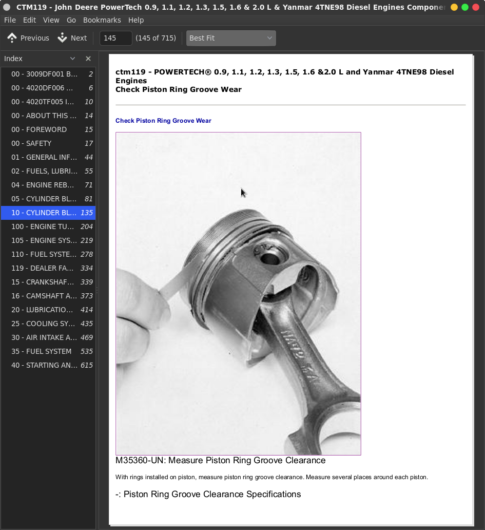
![]()