
John Deere 317 and 320 Skid Steer Loader CT322 Compact Track Loader Operation & Test Service Manual - TM2151

Complete Operation & Test technical manual with electrical wiring diagrams for John Deere 317 and 320 Skid Steer Loader CT322 Compact Track Loader, with workshop information to maintain, diagnose, and service like professional mechanics.
John Deere 317 and 320 Skid Steer Loader CT322 Compact Track Loaders workshop service repair manual includes:
* Numbered table of contents easy to use so that you can find the information you need fast.
* Detailed sub-steps expand on repair procedure information
* Numbered instructions guide you through every repair procedure step by step.
* Troubleshooting and electrical service procedures are combined with detailed wiring diagrams for ease of use.
* Notes, cautions and warnings throughout each chapter pinpoint critical information.
* Bold figure number help you quickly match illustrations with instructions.
* Detailed illustrations, drawings and photos guide you through every procedure.
* Enlarged inset helps you identify and examine parts in detail.
TM2151 - John Deere 317 and 320 Skid Steer Loader CT322 Compact Track Loader (Operation & Test).epub
TM2151 - John Deere 317 and 320 Skid Steer Loader CT322 Compact Track Loader (Operation & Test).pdf
Total Pages: 532 pages
File Format: PDF (bookmarked, ToC, Searchable, Printable, high quality) & EPUB/MOBI/AZW for Kindle/iPad/iPhone/Android.
Language: English
TABLE OF CONTENTS
Foreword
Technical Information Feedback Form
General Information
Safety
Operational Checkout Procedure
Operational Checkout Procedure
Engine
Theory Of Operation
Diagnose Observable Machine Symptoms
Tests
Electrical System
System Information
System Diagrams
Sub-System Diagnostics
References
Power Train
Theory Of Operation
Diagnostic Information
Tests
Hydraulic System
Theory Of Operation
Diagnostic Information
Tests
Hydrostatic System
Theory Of Operation
Diagnostic Information
Tests
Heating and Air Conditioning
Theory Of Operation
Diagnostic Information
Tests
Total Pages: 490 pages
File Format: PDF (bookmarked, Searchable, Printable, high quality PDF)
Language: English
CONTETNS - Expanded Views
0000 - Foreword
9000 - GENERAL INFORMATION
01 - Safety
Add and Operate Attachments Safely
Avoid Backover Accidents
Avoid High-Pressure Oils
Avoid Machine Tip Over
Avoid Unauthorized Machine Modifications
Avoid Work Site Hazards
Beware of Exhaust Fumes
Dispose of Waste Properly
Drive Metal Pins Safely
Follow Safety Instructions
Handle Chemical Products Safely
Inspect Machine
Keep Riders Off Machine
Make Welding Repairs Safely
Operate Only If Qualified
Operating or Traveling On Public Roads
Park And Prepare For Service Safely
Prepare for Emergencies
Prevent Battery Explosions
Prevent Fires
Prevent Unintended Machine Movement
Recognize Safety Information
Remove Paint Before Welding or Heating
Service Cooling System Safely
Start Only From Operator's Seat
Stay Clear of Moving Parts
Use and Maintain Seat Belt
Use Steps and Handholds Correctly
Wear Protective Equipment
01 - Safety
9000 - GENERAL INFORMATION
9005 - OPERATIONAL CHECKOUT PROCEDURE
10 - Operational Checkout Procedure
Operational Checkout
10 - Operational Checkout Procedure
9005 - OPERATIONAL CHECKOUT PROCEDURE
9010 - ENGINE
05 - Theory of Operation
POWERTECH ® 2.4 L & 3.0 L (4024 & 5030) John Deere Engines
05 - Theory of Operation
15 - Diagnostic Information
2.4 L & 3.0 L Diesel Engine for 317 & 320 Skid Steer Loader and CT322 Compact Track Loader
Engine Fuel System Component Location
15 - Diagnostic Information
25 - Tests
Engine Power Test Using Turbocharger Boost Pressure
Engine Speed Test and Adjustment
25 - Tests
9010 - ENGINE
9015 - ELECTRICAL SYSTEM
05 - System Information
12 Volt Auxiliary Power Harness (W9) Component Location
12 Volt Auxiliary Power Harness (W9) Wiring Diagram
8-Button Controller Harness (W15) Component Location
8-Button Controller Harness (W15) Wiring Diagram
Air Conditioner and Heater Harness (W7) Component Location
Air Conditioner and Heater Harness (W7) Wiring Diagram
Back-Up Alarm Harness (W4) Component Location
Back-Up Alarm Harness (W4) Wiring Diagram
Beacon Harness (W10) Component Location
Beacon Harness (W10) Wiring Diagram
Cab Harness—Deluxe (W12) Component Location
Cab Harness—Deluxe (W12) Wiring Diagram
Cab Harness—Standard (W2) Component Location
Cab Harness—Standard (W2) Wiring Diagram
CTL Front Chassis Harness—Deluxe (W17) Component Location
CTL Front Chassis Harness—Deluxe (W17) Wiring Diagram
CTL Front Chassis Harness—Standard (W16) Component Location
CTL Front Chassis Harness—Standard (W16) Wiring Diagram
Dual Flasher Harness (W5) Component Location
Dual Flasher Harness (W5) Wiring Diagram
Electrical Diagram Information
Electric Quik-Tatch (W28) Component Location (S.N. 131877— )
Electric Quik-Tatch (W28) Wiring Diagram (S.N. 131877— )
Engine Harness (W1) Component Location
Engine Harness (W1) Wiring Diagram
Front Chassis Harness—Deluxe (W13) Component Location
Front Chassis Harness—Deluxe (W13) Wiring Diagram
Front Chassis Harness—Standard (W3) Component Location
Front Chassis Harness—Standard (W3) Wiring Diagram
Fuse Specifications
Helper Fan Control and Tee Harness (W29 and W30) Component Location
Helper Fan Control and Tee Harness (W29 and W30) Wiring Diagram
Horn Harness (W6) Component Location
Horn Harness (W6) Wiring Diagram
License Plate Light Harness (W39) Component Location—If Equipped
License Plate Light Harness (W39) Wiring Diagram—If Equipped
Operator Convenience Package Harnesses (W18 and W19) Component Location
Operator Convenience Package Harnesses (W18 and W19) Wiring Diagram
System Functional Schematic and Section Legend
System Functional Schematic, Wiring Diagram, and Component Location Master Legend
Water-in-Fuel Indicator Harness (W37) and Water-in-Fuel Sensor Harness (W38) Component Location—If Equipped
Water-in-Fuel Indicator Harness (W37) Wiring Diagram—If Equipped
Water-in-Fuel Sensor Harness (W38) Wiring Diagram—If Equipped
Wiper Harness (W8) Component Location
Wiper Harness (W8) Wiring Diagram
05 - System Information
10 - System Diagrams
15 - Sub-System Diagnostics
Back-Up Alarm Circuit Theory of Operation
Electric Quik-Tatch Theory of Operation (S.N. 131877— )
Engagement and Monitor Unit Circuit Theory of Operation
Starting Circuit Theory of Operation
15 - Sub-System Diagnostics
20 - References
Alternator Test
Anti-Theft Security System Operation—If Equipped
Back-Up Alarm Remove and Install
Battery Remove and Install
Diagnostic Trouble Codes
Diagnostic Trouble Codes Quick Reference
Electrical Component Checks
Electrical Component Specifications
Engagement and Monitor Unit Data Items
Engagement and Monitor Unit Initial Configuration
Engagement and Monitor Unit Operation
Fuse Test
Install DEUTSCH ™ Contact
Install WEATHER PACK ™ Contact
Instrument Panel, Engagement and Monitor Unit, and Key Switch Remove and Install
Reading Engagement and Monitor Unit Diagnostic Trouble Codes
Relay Test
Replace DEUTSCH ™ Connectors
Replace DEUTSCH ™ Rectangular or Triangular Connectors
Replace (Pull Type) Metri-Pack™ Connectors
Replace (Push Type) Metri-Pack™ Connectors
Replace WEATHER PACK ™ Connector
Solenoid Test
Temperature Sensor Test
20 - References
9015 - ELECTRICAL SYSTEM
9020 - POWER TRAIN
05 - Theory of Operation
Chain Case Operation
Drive Axle Operation
Drive Chain Operation
Hydrostatic Motor Gearbox Operation
Power Train System Operation—Compact Track Loader
Power Train System Operation—Skid Steer Loader
Track Adjuster and Recoil Spring Operation
05 - Theory of Operation
15 - Diagnostic Information
Diagnose Power Train Component Malfunctions—Compact Track Loader
Diagnose Power Train Component Malfunctions—Skid Steer Loader
15 - Diagnostic Information
25 - Tests
Check and Adjust Track Sag
Drive Chain Tension Check and Adjustment
25 - Tests
9020 - POWER TRAIN
9025 - HYDRAULIC SYSTEM
05 - Theory of Operation
Control Valve Operation (S.N. —150522)
Control Valve Operation (S.N. 150523— )
Counterbalance Valve Operation—Skid Steer Loader
High Flow Hydraulic Pump Operation
Hydraulic Oil Filter and Park Brake Solenoid Valve Manifold Operation—Skid Steer Loader
Hydraulic Oil Filter Manifold Operation—Compact Track Loader
Hydraulic Pump Operation
Hydraulic Quik-Tatch Operation (S.N. —131876)
Hydraulic System Circuit Symbols
Hydraulic System Operation
Hydraulic System Schematic—Single Speed—Compact Track Loader (S.N. —150522)
Hydraulic System Schematic—Single Speed—Compact Track Loader (S.N. 150523— )
Hydraulic System Schematic—Skid Steer Loader (S.N. —150522)
Hydraulic System Schematic—Skid Steer Loader (S.N. 150523— )
Hydraulic System Schematic—Two Speed—Compact Track Loader (S.N. —150522)
Hydraulic System Schematic—Two Speed—Compact Track Loader (S.N. 150523— )
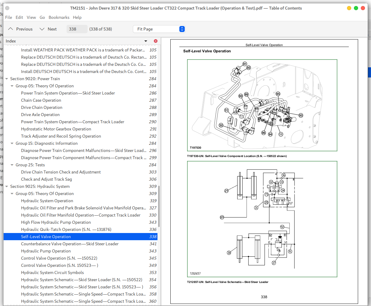
Self-Level Valve Operation
05 - Theory of Operation
15 - Diagnostic Information
Diagnose Hydraulic System Malfunctions
15 - Diagnostic Information
25 - Tests
Boom and Bucket Spool Lock Solenoid Test
Charge Pressure Relief Valve Test
Circuit Relief Valve Test (S.N. —150522)
Circuit Relief Valve Test (S.N. 150523— )
Counterbalance Valve Test and Adjustment—Skid Steer Loader
Hydraulic Pump Flow Test
Hydraulic System Pressure Release Cable Adjustment
Hydraulic System Pressure Release
JT02156A Digital Pressure _ Temperature Analyzer Installation
JT05800 Digital Thermometer Installation
Port Lock Solenoid Valve and Port Lock Spool Test
Remote Start Box Installation
System Relief Valve Test (S.N. —150522)
System Relief Valve Test (S.N. 150523— )
25 - Tests
9025 - HYDRAULIC SYSTEM
9026 - HYDROSTATIC SYSTEM
05 - Theory of Operation
Hydrostatic Motor Operation—Single Speed—Compact Track Loader
Hydrostatic Motor Operation—Skid Steer Loader
Hydrostatic Motor Operation—Two Speed—Compact Track Loader
Hydrostatic Pump Operation
Hydrostatic System Operation
Park Brake Solenoid Valve Manifold Operation—Compact Track Loader
Park Brake System Operation
Steering Control Operation
Two Speed Proportional Solenoid Valve Operation—Compact Track Loader
05 - Theory of Operation
15 - Diagnostic Informtion
Diagnose Hydrostatic System Malfunctions
Diagnose Park Brake System Malfunctions—Compact Track Loader
Diagnose Park Brake System Malfunctions—Skid Steer Loader
Diagnose Steering System Malfunctions
15 - Diagnostic Informtion
25 - Tests
Auxiliary Hydraulic Control Handle Adjustment
Centering Plate Adjustment—Compact Track Loader
Centering Plate Adjustment—Skid Steer Loader
Hydraulic Control Handle Adjustment—Hands Only Machine
Hydrostatic Pump Case Drain Test
Hydrostatic Pump Flow Test
Hydrostatic Pump System Pressure Relief Test
Park Brake Release Pressure Test
Steering Lever Adjustment—Centering
Tracking Adjustment—Compact Track Loader
Tracking Adjustment—Skid Steer Loader
Track Speed Test—Compact Track Loader
Wheel Speed Test—Skid Steer Loader
25 - Tests
9026 - HYDROSTATIC SYSTEM
9031 - HEATING AND AIR CONDITIONING
05 - Theory of Operation
Air Conditioning System Cycle Of Operation
05 - Theory of Operation
15 - Diagnostic Information
Air Conditioner and Heater Component Location
Diagnose Air Conditioning System Malfunctions
Diagnose Heater System Malfunctions
15 - Diagnostic Information
25 - Tests
Air Conditioner and Heater Operational Checks
Air Conditioner Compressor Clutch Test
Air Conditioner Freeze Control Switch Test
Air Conditioner High _ Low Pressure Switch Test
Operating Pressure Diagnostic Chart
R134a Air Conditioning System Test
Refrigerant Cautions and Proper Handling
Refrigerant Leak Test
25 - Tests
9031 - HEATING AND AIR CONDITIONING
John Deere 317 and 320 Skid Steer Loader CT322 Compact Track Loader Operation & Test Service Manual - TM2151
![]()