
Takeuchi Dump Carrier TCR50 Repair Service Manual
Takeuchi Dump Carrier TCR50 Repair Service Manual
Complete service repair manual for Takeuchi Dump Carrier TCR50, with all the shop information to maintain, diagnostic, repair, refurbish/rebuild like professional mechanics.
Takeuchi Dump Carrier TCR50 workshop service & repair manual includes:
* Numbered table of contents easy to use so that you can find the information you need fast.
* Detailed sub-steps expand on repair procedure information
* Numbered instructions guide you through every repair procedure step by step.
* Troubleshooting and electrical service procedures are combined with detailed wiring diagrams for ease of use.
* Notes, cautions and warnings throughout each chapter pinpoint critical information.
* Bold figure number help you quickly match illustrations with instructions.
* Detailed illustrations, drawings and photos guide you through every procedure.
* Enlarged inset helps you identify and examine parts in detail.
PRODUCT DETAILS:
Total Pages/Size: 302 pages
File Format: PDF (bookmarked, ToC, Searchable, Printable, high quality)
Language: English
Delivery: instant download link displayed on page & emailed to you after checkout
Protection: DRM-free; without any restriction
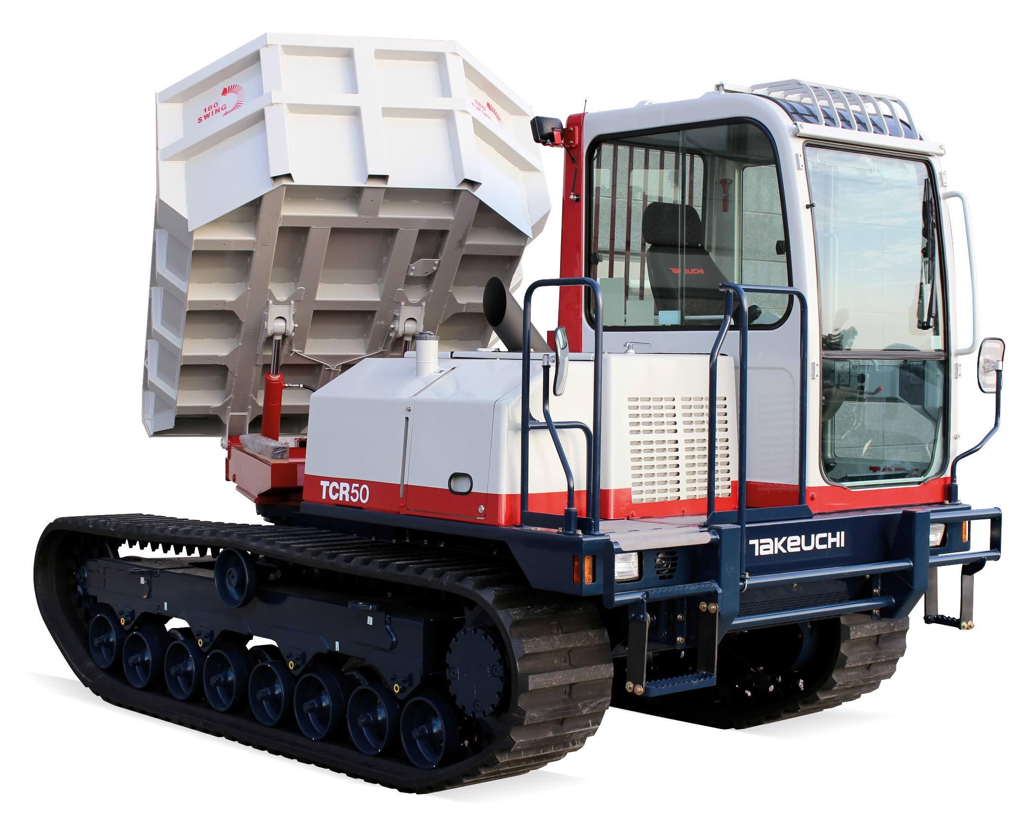
Takeuchi Dump Carrier TCR50 Workshop Manual; 302 pages; Serial Number: 30500003~ 30500038~ 30510001~.
TABLE OF CONTENTS
1. General Cautions for Maintenance Work
1-1. Correct Work ... 1-1
1-2. Safety Precautions ... 1-1
1-3. Preparations ... 1-7
1-4. Cautions for Disassembly and Reassembly ... 1-7
1-5. Cautions for Removal and Installation of Hydraulic Equipment ... 1-8
1-6. Cautions for Removal and Installation of Hydraulic Piping ... 1-8
1-7. Cautions for Handling Seals ... 1-9
1-8. Correct Installation of Hydraulic Hose ... 1-10
1-9. Types of Hydraulic Hoses ... 1-11
1-10. How to Release Air from Hydraulic Units ... 1-15
1-10-1. Releasing Air from the HST System ... 1-15
1-10-2. Releasing Air from Hydraulic Cylinder ... 1-16
2. Technical Data
2-1. Specifications ... 2-1-1
2-2. Outside Drawing ... 2-2-1
2-3. Hydraulic Circuit Diagram ... 2-3-1
2-4. Electrical Circuit Diagram ... 2-4-1
3. Servicing Standards
3-1. Machine Performance ... 3-1-1
3-1-1. Reference Value Table ... 3-1-1
3-1-2. Methods for Inspecting Performance ... 3-1-2
3-2. Engine Servicing Standards (S/N: 30500003~30500038) ... 3-2-1
3-3. Servicing Standards for Parts of Undercarriage ... 3-3-1
3-4. Control Equipment ... 3-4-1
3-5. Hydraulic Equipment ... 3-4-1
3-5-1. Hydraulic Cylinder ... 3-4-1
3-6. Tightening Torque Table ... 3-6-1
3-6-1. Tightening Torque for Bolts and Nuts for Vehicle ... 3-6-1
3-6-2. Tightening Torque for Bolts and Nuts for Engine (S/N: 30500003~30500038) ... 3-6-2
4. Engine Servicing Procedure (S/N: 30500003~30500038)
4-1. Inspection and Adjustment ... 4-1-1
4-1-1. Oil Inspection ... 4-1-1
4-1-2. Cooling Water Inspection ... 4-1-1
4-1-3. Inspecting Water Leak from Cooling Water System and Rediator ... 4-1-1
4-1-4. Fan Belt Tension Inspection and Adjustment ... 4-1-2
4-1-5. Adjusting the Valve Clearance ... 4-1-3
4-1-6. Inspecting the Fuel Injection Valve Injection Pressure and Spray Pattern ... 4-1-4
4-1-7. Fuel Injection Timing Inspection and Adjustment ... 4-1-8
4-1-8. Adjusting the No-load Maximum (or Minimum) Revolutions ... 4-1-9
4-1-9. Sensor Inspection ... 4-1-10
4-2. Engine Body ... 4-2-1
4-2-1. Introduction ... 4-2-1
4-2-2. Cylinder Head ... 4-2-2
4-2-3. Gear Train and Camshaft ... 4-2-11
4-2-4. Cylinder Block ... 4-2-17
4-3. Lubrication System ... 4-3-1
4-3-1. Lubrication System Diagram ... 4-3-1
4-3-2. Trochoid Pump Components ... 4-3-1
4-3-3. Disassembly (Reverse the procedure below for assembly) ... 4-3-24-3-4. Servicing Points ... 4-3-2
4-3-5. Parts Inspection and Measurement ... 4-3-2
4-4. Cooling System ... 4-4-1
4-4-1. Cooling Water System ... 4-4-1
4-4-2. Cooling Water Pump Components ... 4-4-1
4-4-3. Disassembly (Reverse the procedure below for assembly) ... 4-4-2
4-4-4. Servicing Points ... 4-4-2
4-5. Fuel Injection System/Governor ... 4-5-1
4-5-1. Introduction ... 4-5-1
4-5-2. Fuel Injection Pump ... 4-5-1
4-5-3. Fuel Injection Valve ... 4-5-7
4-5-4. Fuel Feed Pump ... 4-5-7
4-5-5. Governor ... 4-5-8
4-5-6. Special Service Tools for Disassembly/Assembly ... 4-5-9
4-6. Starting Motor ... 4-6-1
4-6-1. Specifications ... 4-6-1
4-7. Alternator ... 4-7-1
4-7-1. Specifications ... 4-7-1
4-8. Special Service Tools ... 4-8-1
4-8-1. Special Tools ... 4-8-1
4-8-2. Measuring Instruments ... 4-8-3
5. Hydraulic System
5-1. Hydraulic Units ... 5-1-1
5-1-1. Hydraulic Pump (S/N: 30500003~30500038) ... 5-1-1
5-1-2. Hydraulic Pump (S/N: 30510001~ ) ... 5-1-5
5-1-3. Gear Pump (S/N: 30510001~ ) ... 5-1-35
5-1-4. Travel Motor (S/N: 30500003~30500038) ... 5-1-41
5-1-5. Travel Motor (S/N: 30510001~ ) ... 5-1-45
5-1-6. Swing Motor ... 5-1-71
5-1-7. Control Valve ... 5-1-93
5-1-8. Solenoid Valves ... 5-1-107
5-1-9. Pilot Valve ... 5-1-113
5-1-10. Swivel Joint ... 5-1-123
5-1-11. Cylinders ... 5-1-129
5-2. Pressure Adjustments ... 5-2-1
5-3. Precautions in Case of Hydraulic Source Failures ... 5-3-1
6. Service Procedures for Individual Components
6-1. Undercarriage ... 6-1-1
6-1-1. Removing and Installing the Crawler ... 6-1-1
6-1-2. Removing and Installing the Travel Motor ... 6-1-4
6-1-3. Disassembling and Assembling the Idler ... 6-1-6
6-1-4. Disassembling and Assembling the Carrier Roller ... 6-1-9
6-1-5. Disassembling and Assembling the Track Roller ... 6-1-11
6-1-6. Installing the Floating Seal ... 6-1-19
6-1-7. Removing and Installing the Shoe Tension Cylinder ... 6-1-20
7. Fuel, Lube Oil and Grease Recommended
7-1. Fuel, Lube Oil and Grease Recommended ... 7-1-1
8. Troubleshooting
8-1. Phenomenon That is not a Machine Failure ... 8-1-1
8-2. Troubleshooting ... 8-2-1
8-3. HST Troubleshooting ... 8-3-1
![]()