
John Deere Tractors 5403, 5600, 5605, 5700, 5705 Diagnostic and Repair Service Manual (TM4812)
Complete All Inclusive Technical Manual with electrical wiring diagrams for John Deere Tractors 5403, 5600, 5605, 5700, 5705 Brazil, with all the technical information to maintain, diagnose, repair, rebuild like professional mechanics (Diagnosis, Operation, Tests, Repair, Service, Troubleshooting).
John Deere Tractors 5403, 5600, 5605, 5700, 5705 workshop technical service manual includes:
* Numbered table of contents easy to use so that you can find the information you need fast.
* Detailed sub-steps expand on repair procedure information
* Numbered instructions guide you through every repair procedure step by step.
* Troubleshooting and electrical service procedures are combined with detailed wiring diagrams for ease of use.
* Notes, cautions and warnings throughout each chapter pinpoint critical information.
* Bold figure number help you quickly match illustrations with instructions.
* Detailed illustrations, drawings and photos guide you through every procedure.
* Enlarged inset helps you identify and examine parts in detail.
tm4812 - tractors 5403, 5605 and 5705 Technical Manual.pdf
tm4812 - tractors 5403, 5605 and 5705 Technical Manual.epub
PRODUCT DETAILS:
Total Pages: 971 pages
File Format: PDF/EPUB/MOBI/AZW (PC/Mac/Android/Kindle/iPhone/iPad; bookmarked, ToC, Searchable, Printable)
Language: English
MAIN SECTIONS
Foreword
General Information
Safety
Repairing the Electric System
Battery, Starter Motor and Alternator
Electric System Components
Electric Wiring Harness
Repairing the Power Train
Clutch - TSS Transmission
Carraro Clutch Assembly - (up to series 13693)
LUK Clutch Assembly - (as from series 13694)
TSS Transmission
PTO Drive Shaft
Differential
Final Drive
Mechanical Front Wheel Drive
Repairing the Steering and Brakes
Steering Repair
Brakes Repair
Steering Cylinder - 2WD Axle
Hydraulic Repair
Hydraulic Pump and Filter
Bosch Hydraulic Pump
Hydraulic Oil Cooler
Rockshaft
Selective Control Valve
Third Remote Control Valve
Mechanical Front Wheel Drive
MFWD Special Tools
Technical Data and Adjustment Values
Disassembly
Assembling the Differential
Pinion Depth
Adjusting Backlash
Housing Assemble
Assemble MFWD Axle Shaft
Planetary Gear
Assemble Hydraulic Cylinder
Toe-In Adjustment
ROPS
Roll Over Protection Structure - ROPS
Electric System: Operation and Tests
Location of the Components
Multitest Identification
Electrical System Theory of Operation
Diagnosing, Checking and Adjusting the Electrical System
General Electric Schematic
Transmission: Operation, Tests and Adjustments.
Location of Components - Transmission TSS
Carraro Clutch - Theory of Operation
Eaton Clutch and Transmission TSS -Theory of Operation -
Diagnostics, Tests and Adjustments - TSS Transmission
Brake and Steering: Operation, Tests and Adjustments.
Location of the Components
Steering and Brake -Theory of Operation
Steering and Brake - Diagnosis, Tests and Adjustments
Hydraulics: Operation, Tests and Adjustments.
Location of the Components
Digital Temperature and Presure Analyzer
Hydraulic System - Theory of Operation
Hydraulic System - Diagnosis
Hydraulic Tests-Without SCV
Hydraulic Tests-With SCV
Hydraulic Tests-All
Adjustments
Hydraulic Schematics
Others
tm4812 - tractors 5403, 5605 and 5705
Table of Contents
Foreword
Section 10: General Information
Group 05: Safety
Recognize Safety Information
Understand Signal Words
Follow Safety Instructions
Handle Fluids Safely-Avoid Fires
Prevent Battery Explosions
Prepare for Emergencies
Prevent Acid Burns
Service Cooling System Safely
Handle Chemical Products Safely
Avoid High-Pressure Fluids
Park Machine Safely
Support Machine Properly
Wear Protective Clothing
Work in Clean Area
Service Machines Safely
Work in Ventilated Area
Illuminate Work Area Safely
Replace Safety Signs
Use Proper Lifting Equipment
Keep ROPS Installed Properly
Service Tires Safely
Avoid Harmful Asbestos Dust
Avoid Heating Near Pressurized Fluid Lines
Remove Paint Before Welding or Heating
Use Proper Tools
Dispose of Waste Properly
Live With Safety
Section 40: Repairing the Electric System
Group 05: Battery, Starter Motor and Alternator
Removing and Installing the Battery
Removing and Installing the Starter Motor
Replacing the Alternator/Regulator
Group 10: Electric System Components
Other Material
Replacing the Air Filter Restriction Sensor
Replacing the Coolant Temperature Sensor
Replacing the Engine Speed Sensor
Replacing the Fuel Shut Off Solenoid
Replacing the Engine Oil Pressure Switch
Replacing the Key Switch
Replacing the Tractor Light Switch
Replacing the Direction Indicator Command
Replacing the Dashboard
Replacing the PTO Switch
Replacing the Starter Protection Switch
Replacing the Fuel Level Sender
Group 15: Electric Wiring Harness
Special Tools
Replace Connector Body-Blade Terminals
Replace WEATHER PACK WEATHER PACK is a trademark of Packard Electric. Connector
Install WEATHER PACK WEATHER PACK is a trademark of Packard Electric. Contact
Replacing the Front Electric Wiring Harness
Replace the Rear Electric Harness
Replacing the Battery Harness
Replacing the Rear Working Lights Harness
Section 50: Repairing the Power Train
Group 05: Clutch - TSS Transmission
Other Material
Separate Engine from Clutch Housing
Install Engine to Clutch Housing
Replacing the Clutch Housing Seal
Inspect and Repair Clutch Pedal and Linkage
Adjusting the Clutch Pedal Free Play
Group 10: Carraro Clutch Assembly - (up to series 13693)
Essential or Special Tools
Special Tools
Other Material
Remove and Install the Clutch Assembly
Disassemble and Inspect the Clutch Assembly
Assemble the Clutch Assembly
Adjust the Traction Clutch Finger
Adjust the PTO Clutch Release Finger
Remove and Check the Clutch and Shafts Release Mechanism
Install Clutch Release Mechanism and Shafts
Adjusting the Clutch Pedal Free play
Group 11: LUK Clutch Assembly - (as from series 13694)
Special Tools
Specifications
Remove and Install the Clutch Assembly
Disassemble and Inspect the Clutch Housing
Clutch Assembly
Adjust the Traction Clutch Fingers
Adjusting the PTO Clutch Fingers
Group 15: TSS Transmission
Other Material
Separate the Clutch Housing from the Transmission
Install Clutch Housing to Transmission
Inspect and Repair the Gear and Range Shift Levers
Inspect and Repair the Range Shift Lever
Remove Transmission
Disassemble and Inspect Transmission
Assemble Transmission
Install Transmission
Parking Brake Components for Tractors as from 18041 Series
Install Park Brake Components (park)
Disassemble, Inspect and Assemble the Gear Shift Shaft Assemblies
Disassemble, Inspect and Assemble the Top Transmission Shaft - Transmission with Synchronized Top Shaft (TSS)
Top Mounted Shaft
Assemble Top Shaft
Exploded View of the Top Shaft Collar Shift
Disassemble, Inspect, and Assemble Range Reduction Shaft
Disassemble, Inspect and Assemble Driven Shaft
Remove, Inspect and Install MFWD and Range Gears
Remove, Inspect and Install Reverse Idler Shaft.
Group 20: PTO Drive Shaft
Other Material
Inspect and Repair the PTO Lever and Linkage
Remove and Install the PTO Drive Shaft Assembly
Disassemble, Inspect and Assemble Standard Rear PTO Drive Shaft Assembly
Group 25: Differential
Essential or Special Tools
Remove and Install Differential Assembly
Disassemble, Inspect, and Assemble Differential Assembly
Remove and Inspect Differential Drive Shaft
Install Differential Drive Shaft
Remove, Inspect, and Install Differential Lock Assembly
Differential Cone Point Adjustment
Differential Backlash Adjustment
Group 30: Final Drive
Tools and Service Equipment
Final Drive Turn Tool
Other Material
Remove and Install Final Drive Assembly
Remove and Inspect Planetary Drive Assembly
Install Planetary Drive Assembly
Remove, Inspect, and Install Axle Shaft Assembly
Group 35: Mechanical Front Wheel Drive
Special or Essential Tools
Other Material
Inspect and Repair the MFWD Lever and Linkage
Remove and Install the MFWD Drop Gearbox
Disassemble and Inspect MFWD Drop Gearbox
MFWD Drop Gearbox Cross Section
Assemble MFWD Drop Gearbox
Remove, Inspect and Install MFWD Drive Shaft
Section 60: Repairing the Steering and Brakes
Group 05: Steering Repair
Other Material
Special Tool
Replacement Kits
Remove and Install the Steering Column Valve
Disassemble and Inspect the Steering Valve
Assembling Steering Valve
Inspect and Replace the Steering Hydraulic Lines (Without Oil Cooler)
Inspect and replace the Steering Hydraulic Lines (With Oil Cooler)
Group 10: Brakes Repair
Other Material
Remove and Install the Brake Valve and Pedals
Disassemble and Inspect Brake Valve
Brake Valve Cross Section
Assemble Brake Valve
Remove and Inspect Brakes.
Install Brakes
Inspect and Replace Brake Hydraulic Lines
Group 15: Steering Cylinder - 2WD Axle
General Information
Special Tools
Specifications
Remove Steering Cylinder
Disassemble Steering Hydraulic Cylinder
Assembling the Hydraulic Cylinder
Install the steering cylinder
Section 70: Hydraulic Repair
Group 05: Hydraulic Pump and Filter
Remove, Inspect and Install Mesh Filter
Remove and Install the Hydraulic Pump
Remove Hydraulic Pump External Components
Assemble the Hydraulic Pump
Install External Hydraulic Pump Components
Remove and Install the Hydraulic/Tubing Filter
Inspect and Replace the Return/Supply Hydraulic Lines
Group 05A: Bosch Hydraulic Pump
Hydraulic Pump
Remove and Install Hydraulic Pump
Remove Hydraulic Pump External Components
Disassemble Hydraulic Pump
Assemble Bosch Hydraulic Pump
Group 06: Hydraulic Oil Cooler
Remove, inspect and install the Hydraulic Oil Cooler-5705
Group 10: Rockshaft
Other Material
Inspect and Repair Rockshaft Control Lever
Inspect and Repair Rockshaft Control Mechanism
Inspect and Repair the Draft Support Assembly
Replace Main Relief Valve
Replace Rockshaft Surge Relief Valve
Remove, Inspect and Install Rate-of-drop Valve
Replace the Hydraulic Lift Control Valve
Remove and Install the Rockshaft Case
Remove, Inspect, and Install Rockshaft Lift Arms
Remove, Inspect, and Install Rockshaft Piston and Cylinder
Group 15: Selective Control Valve
Other Material
Disassemble, Inspect, and Assemble Dual Selective Control Valve (SCV)-Straddle Mount Tractors
Checking and Replacing the Hydraulic Hoses-Double Remote Control Valve
Group 16: Third Remote Control Valve
Other Material
Check and Repair the Lever and Linkage.
Remove and Install the Third Selective Control Valve.
Disassemble, Inspect and Assemble the third Selective Control Valve.
Check and Replace the hydraulic hoses-Third Selective Control Valve
Section 80: Mechanical Front Wheel Drive
Group 05: MFWD Special Tools
Special Tools
Group 10: Technical Data and Adjustment Values
Technical Data and Adjustment Values
Group 15: Disassembly
Disassemble MFWD Outer Drive
Group 20: Assembling the Differential
Assembly
Group 25: Pinion Depth
Pinion depth
Group 30: Adjusting Backlash
Adjust the Backlash
Group 35: Housing Assemble
Assemble the Housing
Group 40: Assemble MFWD Axle Shaft
Assemble MFWD Axle Shaft
Group 45: Planetary Gear
Planetary Gear
Group 50: Assemble Hydraulic Cylinder
Assemble Hydraulic Cylinder
Group 55: Toe-In Adjustment
Toe-In Adjustment
Section 90: ROPS
Group 10: Roll Over Protection Structure - ROPS
Remove and Install the ROPS
Section 240: Electric System: Operation and Tests
Group 05: Location of the Components
Information about the Location of the Components
Engine Electrical Components
Dashboard Components
Tractor Electrical Components
Group 06: Multitest Identification
Voltage Measurements
Low Voltage Electrical Current Measurements
Measuring the Electrical Current - Up to 10 Amperes
Resistance Measurements
Continuity Measurements
Temperature Measurements
Group 10: Electrical System Theory of Operation
Theory of Operation information
Fuse box
Fuse box
Fuse Size and Function - 5403 Tractor
Relays - 5403 Tractor
Relays
Starter Motor Operation
Charging System Operation
Lighting System Operation
Light Circuit
Direction Indicator
Hazard Lights
Field Lights
Transport Lights
Dashboard System Operation
PTO System Operation
Brake System Operation
Group 15: Diagnosing, Checking and Adjusting the Electrical System
Diagnostic Information
Wire Colors
Starter System Test Points-Normal Operation
Starter system test points-Correct Operation
Charging System Test Points.
Light System Test Points-Direction Indicators
Light System Test Points-Hazard lights
Light system test points-Field lights
Light System Test Points-Transport Lights
Dashboard System Test Points-Tachometer
Dashboard System Test Points -Fuel gauge
Dashboard System Test Points-Temperature gauge
Dashboard System Test Points-Oil Pressure
Dashboard System Test Points-Air Filter Blockage
Dashboard System Test Points-Hour meter
Dashboard System Test Points-PTO
Testing a Delco Freedom Battery.
Recharging the Battery
Important Recommendations about the Battery
Testing the Alternator
Battery Check
Testing the Starter motor Solenoid.
Testing the Starter Relay
Testing the Start Switch.
Testing the Relay
Testing the Diode Block.
Fuse Test.
Testing the Starter Protection Sensor
Testing the PTO Sensor
Testing the light Switch.
Turn Signal Controller Test
Test the Fuel Shut Off Solenoid.
Group 20: General Electric Schematic
Schematic Information
Electrical Circuit - Tractor 5403
Electrical Circuit - Tractor 5403-Continuation
Electrical Circuit - Tractor 5403-Continuation
Section 250: Transmission: Operation, Tests and Adjustments.
Group 05: Location of Components - Transmission TSS
Information Regarding the Location of Components
Drive Train Components
Clutch Components
Transmission Components-TSS
Final Drive Components
Rear PTO Components
Group 10 A: Carraro Clutch - Theory of Operation
Clutch Operation - Carraro
Clutch Operation - Continuation
Clutch Operation - Continuation
Group 10 B: Eaton Clutch and Transmission TSS -Theory of Operation -
Information on the Theory of Operation
Clutch Operation-CollarShift and SyncShuttle™ Transmissions
Transmission Lubrication System
CollarShift Transmission-Gear Shift Power Flow
SyncShuttle™ Transmission-Gear Shift Power Flow
SyncShuttle™ Transmission Synchronizer Operation-Reverse and 2nd Gear (Disk-and-Plate Type Synchronizer)
SyncShuttle™ Transmission Synchronizer Operation-1st and 3rd Gear (Cone-Type Synchronizer)
CollarShift Transmission-Shift Range Power Flow
Rear PTO Operation
Rear PTO Operation
Differential Power Flow
Differential Power Flow
Differential Lock Operation
Differential Lock Operation
Final Drive Operation
Mechanical Front Wheel Drive (MFWD) Drop Gearbox Operation
Mechanical Front Wheel Drive (MFWD) Drop Gearbox Operation
Group 15: Diagnostics, Tests and Adjustments - TSS Transmission
Diagnostic Information
Isolate the Problem Area
Isolate the Problem Area - Continued
The Traction Clutch Slides
Traction Clutch Drag
Traction Clutch does not Activate
The Traction Clutch Sticks
Traction Clutch Creaking
Traction Clutch does not Release
Traction Clutch Vibrates
The Traction Clutch Creaks
The Traction Clutch Actuation is Noisy
Excessive Vibration on the Traction Clutch
Clutch Pedal does not Return
Loose Clutch Pedal
Clutch Pedal Throbs
Power Transmission Abrupt or Leaping
Transmission Oil Level Low (Excessive Oil Leak)
Gears Present Shock, are Hard to Engage or do not Engage
Two Gears Engage Together
Transmission does not Stay in Gear
Noisy Transmission
Noisy PTO
Hard to Activate PTO
PTO does not Operate
PTO does not Stay Activated
Excessive Differential Noise
Differential does not Work
No Differential Lock
Differential Vibrates
Noisy Shaft
Shaft does not Turn
PTO Lever is Hard to Activate
PTO Shaft in the “On” Position
Noisy FWD Operation
Adjusting the Clutch Pedal Clearance
Adjusting the PTO Clutch Lever
Section 260: Brake and Steering: Operation, Tests and Adjustments.
Group 05: Location of the Components
Information about the Location of the Components
Steering System Components
Brake System Components
Group 10: Steering and Brake -Theory of Operation
Information About the Operation Theory
Steering System Operation
Steering Valve Operation - Manual Turn and Neutral
Steering Valve Operation - Power Assisted Turning
Brake System Operation
Brake Valve Operation
Brake Valve Operation - Continued
Brake Valve Operation - Resting Brake Pedal
Group 15: Steering and Brake - Diagnosis, Tests and Adjustments
Diagnostic Information for the Electric System
Isolate the Problem - Steering System
Slow Steering or Loss of Steering
Isolate the Problem - Brakes
Excessive Brake Pedal Leak
Excessive Brake Vibration
Steering Pump Flow Test
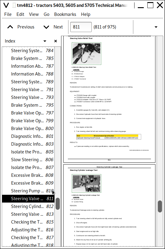
Steering Valve Relief Test
Steering Cylinder Leakage Test
Steering Valve Leakage Test
Checking the Toe-In - Two-Wheel Drive
Adjusting the Toe-In - Two-Wheel Drive
Checking the Toe-In - Four-Wheel Drive
Adjusting the Toe-In - Four-Wheel Drive
Adjusting the Turning Angle of the Steering Backstop - Four-Wheel Drive
Brake Pedal Adjustment
Bleed Brake System
Section 270: Hydraulics: Operation, Tests and Adjustments.
Group 05: Location of the Components
Information about the Location of the Components
Hydraulic System Components
Remote Control Valve Components
Group 06: Digital Temperature and Presure Analyzer
Norms of Safety
Test Applications
Digital Pressure Analyzer
Adjusting
Selecting the Function and Measuring Range
Ranges and Specifications
Group 10: Hydraulic System - Theory of Operation
Information About the Operation Theory
Hydraulic System Operation
Hydraulic Filter Operation
Hydraulic Pump Operation
Rockshaft Control Valve Operation-Two Flow Regulator Valves (Early Model Straddle Mount)
Rockshaft Control Valve Operation-Neutral Position (Early Model Straddle Mount)
Rockshaft Control Valve Operation-Raise Position (Early Model Straddle Mount)
Rockshaft Control Valve Operation-Lower Position (Early Model Straddle Mount)
Surge Relief Valve Operation
Main Relief Valve Operation-Straddle Mount Tractors
Main Relief Valve Operation-Isolated Open Operator Station and Cab Tractors
Rate-of-Drop Valve Operation-Full Open (Straddle Mount)
Rate-of-Drop Valve Operation-Full Open (Isolated Open Operator Station And Cab Tractors)
Rate-of-Drop Valve Operation-Partially Open (Straddle Mount)
Rate-of-Drop Valve Operation-Partially Open (Isolated Open Operator Station and Cab Tractors)
Rate-of-Drop Valve Operation-Full Closed (Straddle Mount)
Rate-of-Drop Valve Operation-Full Closed (Isolated Open Operator Station And Cab Tractors)
Rockshaft Draft-Sensing Operation
SCV Operation-Straddle Mount Tractors (Neutral Position)
SCV Operation-Straddle Mount Tractors (Extend and Retract Positions)
Float SCV Operation-Straddle Mount Tractors (Float Position)
Regenerative SCV Operation-Straddle Mount Tractors (Regenerative Position)
SCV Operation-Isolated Open Operator Station and Cab Tractors (Neutral Position)
SCV Operation-Isolated Open Operator Station and Cab Tractors (Extend and Retract Positions)
Float SCV Operation-Isolated Open Operator Station and Cab Tractors (Float Position)
Regenerative SCV Operation-Isolated Open Operator Station and Cab Tractors (Regenerative Position)
Quick Disconnect Coupler Operation (Straddle Mount)
Quick Disconnect Coupler Operation (Cab and IOOS)
Group 15: Hydraulic System - Diagnosis
Diagnosis information
Preliminary Hydraulic System Inspection
Hydraulic Oil Warm-Up Procedure
Entire Hydraulic System Fails to Function/No Hydraulic Pump Output
Insufficient Pump Delivery
Hydraulic Functions Too Slow
Excessive Pump Pressure
Slow Hydraulic Pump Response
Excessive Pump Noise During Operation
Rockshaft Does Not Lift or Lifts Slowly
Rockshaft Does Not Lower or Lowers Slowly
Neutral Position Unstable, Rockshaft Drops after Engine Shut Down
SCV Control Valve doesReturn to Neutral Position - Third SCV
Remote Cylinder Does Not Extend or Retract
Remote Cylinder Settles Under Load
Remote Cylinder Operates Too Fast or Too Slow
Group 16: Hydraulic Tests-Without SCV
Hydraulic System Tests-Without SCV (Straddle Mount Tractors)
Hydraulic System Tests-Without SCV (Isolated Open Operator Station and Cab Tractors)
Pump Flow Test-Without SCV
Main Relief Valve Test-Without SCV (Straddle Mount Tractors)
Group 17: Hydraulic Tests-With SCV
Hydraulic System Tests-With SCV (Straddle Mount Tractors)
Hydraulic System Tests-With SCV (Straddle Mount Tractors)
Hydraulic System Tests-With SCV (Isolated Open Operator Station and Cab Tractors)
Pump Flow Test-With SCV
Main Relief Valve Test-With SCV
SCV Leakage Test
Group 18: Hydraulic Tests-All
Rockshaft Leakage Test-Straddle Mount
Rockshaft Leakage Test-Isolated Open Operator Station and Cab Tractors
Rockshaft Lift Cycle Test
Group 19: Adjustments
Rockshaft Lever Friction Adjustment
Rockshaft Position-Sensing Feedback Linkage Adjustment
Rockshaft Draft-Sensing Feedback Linkage Adjustment
Main Relief Valve Adjustment-Straddle Mount Tractors
Group 20: Hydraulic Schematics
Hydraulic Circuit Symbols
Hydraulic Schematic-Straddle Mount Tractors (Without SCV)
Hydraulic Schematic-Straddle Mount Tractors (With SCV)
Group 25: Others
Conversion Table
Tool Suppliers
John Deere Tractors 5403, 5600, 5605, 5700, 5705 Diagnostic and Repair Service Manual (TM4812)
![]()