
John Deere Tractors 5055E, 5065E, 5075E Diagnostic and Repair Service Manual (TM901819)
Complete All Inclusive Technical Manual with electrical wiring diagrams for John Deere Tractors 5055E, 5065E, 5075E Asia, Africa, Middle East Edition, with workshop information to maintain, diagnose, and service like professional mechanics (Diagnosis, Operation, Tests, Repair, Service, Troubleshooting).
John Deere Tractors 5055E, 5065E & 5075E workshop technical service repair manual includes:
* Numbered table of contents easy to use so that you can find the information you need fast.
* Detailed sub-steps expand on repair procedure information
* Numbered instructions guide you through every repair procedure step by step.
* Troubleshooting and electrical service procedures are combined with detailed wiring diagrams for ease of use.
* Notes, cautions and warnings throughout each chapter pinpoint critical information.
* Bold figure number help you quickly match illustrations with instructions.
* Detailed illustrations, drawings and photos guide you through every procedure.
* Enlarged inset helps you identify and examine parts in detail.
tm901819 - 5055E, 5065E and 5075E Tractors (March, 2016) Technical Manual.pdf
tm901819 - 5055E, 5065E and 5075E Tractors (March, 2016) Technical Manual.epub
PRODUCT DETAILS:
Total Pages: 1,503 pages
File Format: PDF/EPUB/MOBI/AZW (PC/Mac/Android/Kindle/iPhone/iPad; bookmarked, ToC, Searchable, Printable)
Language: English
MAIN SECTIONS
Foreword
General Information
Safety
General Specifications
Fuel and Lubricants
Serial Number Locations
Features and Accessories
Engine Repair
Engine
Cylinder Head and Valves
Cylinder Block, Liners, Pistons & Rods
Crankshaft, Main Bearings and Flywheel
Camshaft and Timing Gear Train
Lubrication System
Cooling System
Fuel and Air Repair
Fuel System
Air Intake and Exhaust System
Speed Control Linkage
Fuel Shut-Off Linkage
Electrical Repair
Battery, Starter and Alternator
Electrical System Components
Wiring Harness
Power Train Repair
Clutch Housing
Clutch Assembly
Transmission
Rear PTO Drive Shaft
Differential
Final Drives
Mechanical Front Wheel Drive – If Equipped
Steering and Brake Repair
Steering Repair
Brake Repair
Hydraulic Repair
Hydraulic Pump and Filter
MITA Rockshaft
JD Rockshaft
Selective Control Valve (SCV) MITA Rockshaft
Selective Control Valve (SCV) JD Rockshaft
Miscellaneous Repair
Front Axle
Wheels
3-Point Hitch
Operator Station Repair
Seat and Support
Roll-GardROLL-GARD is a trademark of Deere & Company.
Operator Platform
Fenders
Operational Checkout Procedures
Operational Checkout Procedures
Engine Operation, Test and Adjustments
Component Location
Theory of Operation
Diagnosis, Tests and Adjustments
Fuel/Air Operation, Test and Adjustments
Component Location
Theory of Operation
Diagnosis, Tests and Adjustments
Electrical System Operation, Tests and Adjustments
Component Location
Theory of Operation
Diagnosis, Test and Adjust
Wiring Schematics
Power Train Operation, Tests and Adjustments
Component Location
Theory of Operation
Diagnosis, Tests, and Adjustments
Steering and Brake Operation, Test & Adjustments
Component Location
Theory of Operation
Diagnosis, Tests and Adjustments
Hydraulic System Operation, Test and Adjustments
Component Location
Theory of Operation
Diagnosis
Hydraulic Tests - Without SCV
Hydraulic Tests-With SCV
Hydraulic Tests - All
Adjustments - MITA Rockshaft
Adjustments - JDRockshaft
Hydraulic Schematics
tm901819 - 5055E, 5065E and 5075E Tractors (March, 2016)
Table of Contents
Foreword
Section 10: General Information
Group 05: Safety
Recognize Safety Information
Understand Signal Words
Follow Safety Instructions
Handle Fluids Safely—Avoid Fires
Fire Prevention
Prevent Battery Explosions
Prepare for Emergencies
Prevent Acid Burns
Service Cooling System Safely
Avoid High-Pressure Fluids
Park Machine Safely
Support Machine Properly
Wear Protective Clothing
Work in Clean Area
Service Machines Safely
Work In Ventilated Area
Illuminate Work Area Safely
Replace Safety Signs
Use Proper Lifting Equipment
Service Tires Safely
Avoid Harmful Asbestos Dust
Avoid Heating Near Pressurized Fluid Lines
Remove Paint Before Welding or Heating
Use Proper Tools
Decommissioning — Proper Recycling and Disposal of Fluids and Components
Live With Safety
Keep Riders Off Machine
Use Foldable ROPS and Seat Belt Properly
Use Seat Belt Properly
Avoid Backover Accidents
Keep ROPS Installed Properly
Clean Exhaust Filter Safely
Tightening Wheel Retaining Bolts/Nuts
Service Front-Wheel Drive Tractor Safely
Group 10: General Specifications
John Deere 5055E Tractor - JD Asia
John Deere 5055E Tractor - Other than JD Asia
John Deere 5065E Tractor - JD Asia
John Deere 5065E Tractor - Other than JD Asia
John Deere 5075E Tractor - JD Asia
John Deere 5075E Tractor - Other than JD Asia
Repair Specifications
Ground Speeds
Service Recommendations for O-Ring Boss Fittings
Service Recommendations for Flat Face O-Ring Seal Fittings
Metric Bolt and Cap Screw Torque Values
Unified Inch Bolt and Cap Screw Torque Values
Group 20: Fuel and Lubricants
Diesel Fuel
Fuel Storage
Do Not Use Galvanized Containers
Fill Fuel Tank
Diesel Engine Oil
Diesel Engine Coolant (engine with wet sleeve cylinder liners)
Transmission and Hydraulic Oil
Grease (Specific Application)
Grease
Alternative and Synthetic Lubricants
Lubricant Storage
Group 25: Serial Number Locations
Serial Numbers
Product Identification Number Location
Engine Serial Number Location
Fuel Injection Pump Serial Number Location
Alternator Serial Number Location
Power Steering Valve Serial Number Location
Starter Serial Number Location
Transmission Serial Number Location
Front Axle Serial Number Location- 2WD
Front Axle Serial Number Location — Carraro MFWD
Front Axle Serial Number Location — DANA MFWD
Group 30: Features and Accessories
Features and Accessories
Standard Features
Factory Installed Optional Kits
Field Installed Optional Kits and Accessories
Section 20: Engine Repair
Group 05: Engine
Service Equipment and Tools
Specifications
John Deere Engine Repair—Use CTM125
Remove Engine
Install Engine
Engine Disassembly Sequence
Sealant Application Guidelines
Engine Re-Assembly Sequence
Engine Break-In Guidelines
Perform Engine Break-In
Diesel Engine Break-In Oil
Group 10: Cylinder Head and Valves
Special or Essential Tools
Specifications
Torques for Hardware
Cylinder Head - Exploded View
Check Valve Lift
Remove Cylinder Head
Clean Injection Nozzle Bores
Valve Actuating Parts
Remove Valves and Valve Springs
Checking Cylinder Head Flatness
Clean Valve Guides
Measure Valve Guides
Knurl Valve Guides
Clean and Inspect Valve Seats
Lapping Valve Seats
Check Valve Recess
Remove Valve Seat Inserts
Valve Seat Insert Installation
Check Valves
Grind Valves
Check Valve Spring Compression
Inspect Valve Rotators
Install Valves
Install Cylinder Head
Torque Turn Tightening Method
Disassembling and Checking Rocker Arm Shaft
Reassembling Rocker Arm Shaft
Install Rocker Arm Assembly
Valve Clearance
Valve Adjustment Sequence
Install Rocker Arm Cover
Final Work
Group 15: Cylinder Block, Liners, Pistons & Rods
Special or Essential Tools
Specifications
Torques for Hardware
Exploded View
Connecting Rods - General Information
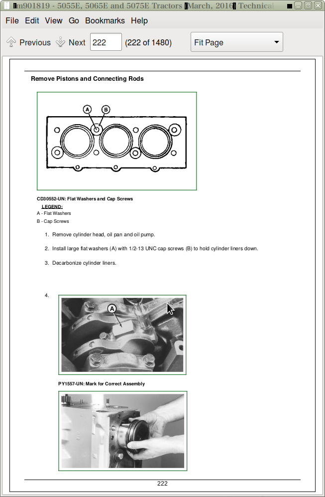
Remove Pistons and Connecting Rods
Measure Cylinder Liner Bore
Remove Cylinder Liners
Cylinder Liner Deglazing
Cylinder Block Cleaning
Check Piston Cooling Jets
Cam Follower Bore Measure
Measure Camshaft Bore
Remove Camshaft Bushing
Install Camshaft Bushing
Measure Crankshaft Bore
Replace Crankshaft Bearing Caps
Cylinder Block Top Desk Flatness
Measure Cylinder Liner Protrusion
Liner Packing Installation
Liner O-Ring Installation
Install Cylinder Liners
Measure Connecting Rod Bearing
Rod Bearing Clearance
Measure Connecting Rod Bushing
Replace Connecting Rod Bushing (3029T)
Measure Piston Pin
Clean and Inspect Pistons
Measure Piston Pin Bore
Piston Top Ring Groove
Second and Third Piston Ring Grooves
Piston Head and Skirt Checking
Install Piston Rings
Piston Rings Staggering
Piston/Liner Set Information
Assemble Piston and Connecting Rod
Install Piston and Connecting Rod
Measure Piston Protrusion
Complete Final Assembly
Group 20: Crankshaft, Main Bearings and Flywheel
Special or Essential Tools
Specifications
Torques For Hardware
Remove Crankshaft Pulley
Install Crankshaft Pulley
Flywheel Removal
Flywheel Ring Gear Replacement
Install Ball Bearing
Install Flywheel
Remove Crankshaft Rear Oil Seal
Flywheel Housing Replacement
Install Oil Seal/Wear Sleeve
Crankshaft End Play Measure
Remove Crankshaft
Crankshaft Inspection
Check Crankshaft Journal Diameter
Determine Crankshaft Main Bearing Clearance Using PLASTIGAGE PLASTIGAGE is a trademark of DANA Corp.
Regrind Crankshaft
Crankshaft Regrinding Guidelines
Micro-Finishing Specifications
Replace Crankshaft Gear
Install Main Bearing Inserts
Install 2-Piece Thrust Bearing
Crankshaft Installation
Group 25: Camshaft and Timing Gear Train
Special or Essential Tools
Specifications
Torques for Hardware
Remove Crankshaft Front Oil Seal
Remove Timing Gear Cover
Measure Timing Gear Backlash
Camshaft End Play Measure
Remove Camshaft
Measure Camshaft Journal
Measure Height of Cam Lobe
Replace Camshaft Gear
Install Camshaft
Check Cam Follower
Idler Gear End Play Measure
Remove Front Plate
Idler Gear Bushing and Shaft Measure
Idler Gear Bushing Replacement
Remove Idler Shaft
Install Idler Shaft Spring Pin
Install Idler Shafts
Install Front Plate
Install Upper Timing Gear Train
Install Lower Timing Gear Train
Install Oil Deflector
Timing Gear Cover Identification
Install Timing Gear Cover
Install Crankshaft Front Oil Seal
Install Wear Ring
Install Auxiliary Equipment
Group 30: Lubrication System
Special or Essential Tools
Specifications
Torques for Hardware
Oil Cooler Identification
Remove Oil Cooler
Replace Oil Cooler Nipple
Install Oil Cooler
Replace Oil Cooler/Filter Bracket on Engine with Auxiliary Drive
Remove Oil Pressure Regulating Valve
Replace Oil Pressure Regulating Valve Seat
Install Oil Pressure Regulating Valve
Replace Oil Dipstick Guide
Replace Oil By-Pass Valve
Replace Oil Pump Strainer
Remove Oil Pump
Oil Pump Gear Axial Clearance
Oil Pump Gear Radial Clearance
Oil Pump Specifications
Oil Pump Installation
Install Oil Pan
Group 35: Cooling System
Special or Essential Tools
Specifications
Torques for Hardware
Remove and Inspect Radiator
Water Pump — Exploded View
Remove Water Pump
Disassemble Water Pump
Assemble Water Pump
Install Water Pump
Inspect Thermostat
Cooling System Deaeration
Check Fan/Alternator Belt Tension
Install Fan
Install Radiator
Replace Thermostat
Section 30: Fuel and Air Repair
Group 05: Fuel System
Special or Essential Tools
Self-Manufactured Tool Template For Front Plate Replacement
Specifications
Torques For Hardware
Injection Pump, Nozzle and Governor Repair—Use CTM125
Remove, Inspect and Install Fuel Tank
Replace Fuel Filter
Remove and Install Fuel Filter/Primer Pump Assembly
Remove Fuel Injection Nozzle
Clean Fuel Injection Nozzle
Fuel Injection Nozzle Disassembly
Install Fuel Injection Nozzle
Group 10: Air Intake and Exhaust System
Remove, Inspect, and Install Air Cleaner Elements
Check Air Inlet Pipe
Check Air Inlet Pipe with Turbocharged––If Equipped
Exhaust Manifold Inspection
Turbocharger Cut-Away View (Borge Warner)––If Equipped
Check Radial Clearance––If Equipped
Check Axial Clearance––If Equipped
Repair Turbocharger––If Equipped
Prelube Turbocharger––If Equipped
Install Turbocharger––If Equipped
Turbocharger Break-In––If Equipped
Recommendations for Turbocharger Use––If Equipped
Group 15: Speed Control Linkage
Inspect and Repair Speed Control Linkage
Group 20: Fuel Shut-Off Linkage
Fuel Shut-Off Linkage—Summary of References
Inspect and Repair Fuel Shut-Off Knob and Linkage (If Applicable)
Section 40: Electrical Repair
Group 05: Battery, Starter and Alternator
Starter Repair—Use CTM
Remove and Install Battery
Remove and Install Starter
Replace Alternator/Regulator
Group 10: Electrical System Components
Service Equipment and Tools
Other Material
Replace Air Filter Restriction Sensor
Replace Coolant Temperature Sender
Replace Engine Speed Sensor
Replace Engine Oil Pressure Sensor
Replace Key Switch
Replace Light Switch
Replace Turn Signal Controller
Replace Instrument Panel
Replace Neutral Start Switch
Replace Fuel Level Sender
Replace 7 Pin Connector
Replace Rear PTO Switch
Replace Park Position Start Switch
Replace Fuel Level Sender
Group 15: Wiring Harness
Special or Essential Tools
Service Parts Kits
Remove Connector Body from Blade Terminals
Replace WEATHER PACK WEATHER PACK is a trademark of Packard Electric. Connector
Install WEATHER PACK WEATHER PACK is a trademark of Packard Electric. Contact
Replace Tractor Wiring Harness
Section 50: Power Train Repair
Group 05: Clutch Housing
Service Equipment and Tools
Other Material
Specifications
Separate Engine from Clutch Housing
Install Engine to Clutch Housing
Replace Clutch Housing Seal
Inspect and Repair Clutch Pedal and Linkage
Group 10: Clutch Assembly
Essential Tools
Service Equipment and Tools
Other Material
Specifications
Remove and Install Clutch Assembly
Disassemble and Inspect Clutch Assembly
Assemble Clutch Assembly
Traction Clutch Finger Adjustment
PTO Clutch Finger Adjustment
Remove and Inspect Clutch Release Mechanism and Shafts
Install Clutch Release Mechanism and Shafts
Group 15: Transmission
Specifications
Separate Clutch Housing From Transmission
Install Clutch Housing to Transmission
Inspect and Repair Gear Shift Lever
Inspect and Repair Range Shift lever
Remove Transmission
Disassemble and Inspect Transmission — SyncShuttle™
Assemble Transmission — SyncShuttle™
Install Transmission
Disassemble, Inspect and Assemble Gear Shift Shaft Assemblies
Disassemble, Inspect, and Assemble Transmission Top Shaft—SyncShuttle™ Transmission
Disassemble, Inspect, and Assemble Range Reduction Shaft
Disassemble, Inspect and Assemble Driven Shaft
Remove, Inspect, and Install Range Gears
Remove, Inspect, and Install Reverse Idler Shaft
Inspect and Repair Park Brake Lever
Remove, Inspect and Repair Park Brake
Group 20: Rear PTO Drive Shaft
Other Material
Specifications
Remove, Inspect and Install Rear PTO Lever and Linkage
Remove and Install Standard Rear PTO Drive Shaft Assembly
Disassemble, Inspect and Assemble Standard Rear PTO Drive Shaft Assembly
Remove, Inspect and Install 540/540E Shift Lever and Linkage – If Equipped
Remove and Install 540/540E Rear PTO Drive Shaft Assembly – If Equipped
Disassemble, Inspect and Assemble Rear 540/540E PTO Drive Shaft Assembly – If Equipped
Group 25: Differential
Essential Tools
Service Equipment and Tools
Other Material
Specifications
Service Parts Kits
Remove and Install Differential Assembly
Disassemble, Inspect, and Assemble Differential Assembly
Remove and Inspect Differential Drive Shaft
Install Differential Drive Shaft
Remove, Inspect, and Install Differential Lock Assembly
Differential Cone Point Adjustment
Differential Backlash Adjustment
Group 30: Final Drives
Service Equipment and Tools
Other Material
Specifications
Remove and Install Final Drive Assembly
Remove and Inspect Planetary Drive Assembly
Install Planetary Drive Assembly
Remove, Inspect, and Install Axle Shaft Assembly
Group 35: Mechanical Front Wheel Drive – If Equipped
Essential Tools
Service Equipment and Tools
Special Tool
Other Material
Specifications
MFWD Axle Repair—Use CTM4870 and CTM4820
Inspect and Repair MFWD Lever and Linkage
Remove and Install MFWD Drop Gearbox
Disassemble and Inspect MFWD Drop Gear box
MFWD Drop Gearbox Cross Section
Assemble MFWD Drop Gearbox
Remove, Inspect and Install MFWD Drive Shaft
Remove and Install MFWD Axle Housing Assembly
Remove, Inspect and Install MFWD Axle Supports (Without Paddy Seal)
Remove, Inspect and Install MFWD Axle Supports (With Paddy Seal)
Section 60: Steering and Brake Repair
Group 05: Steering Repair
Other Material
Specifications
Service Parts Kits
Remove and Install Steering Column and Valve
Disassemble and Inspect Steering Valve
Assemble Steering Valve
Remove and Install Steering Cylinder—2WD Axle
Disassemble, Inspect and Assemble Steering Cylinder—2WD Axle
Remove, Inspect and Install Tie Rod Assembly- 2WD
MFWD Steering Cylinder and Tie Rods — Exploded View
Remove Tie Rods — MFWD
Remove Steering Cylinder — MFWD
Install Steering Cylinder — MFWD
Install Tie Rods — MFWD
Inspect and Replace Steering Hydraulic Lines
Group 10: Brake Repair
Service Equipment and Tools
Other Material
Specifications
Remove and Install Brake Valve and Pedals
Disassemble and Inspect Brake Pedals and Valve
Brake Valve Cross Section
Assemble Brake Valve
Remove and Inspect Brakes
Install Brakes
Inspect and Replace Brake Hydraulic Lines
Section 70: Hydraulic Repair
Group 05: Hydraulic Pump and Filter
Essential Tools
Specifications
Service Parts Kits
Remove, Inspect, and Install Hydraulic Oil Pick-Up Screen
Remove and Install Hydraulic Pump
Remove Hydraulic Pump External Components
Disassemble and Inspect Hydraulic Pump
Assemble Hydraulic Pump
Install Hydraulic Pump External Components
Remove and Install Hydraulic Oil Filter/Manifold
Inspect and Replace Hydraulic Supply and Suction/Return Lines
Group 10: MITA Rockshaft
Other Material
Specifications
Remove, Inspect, and Install Rockshaft Control Lever Assembly
Remove, Inspect, and Install Rockshaft Control Lever Support Assembly
Remove, Inspect and Install Rockshaft Control Linkage
Replace Main Relief Valve
Remove, Inspect and Install Rate-of-Drop Valve
Replace Rockshaft Control Valve- MITA Rockshaft
Remove and Install Rockshaft Case- MITA Rockshaft
Remove, Inspect and Install Rockshaft Lift Arms
Remove, Inspect and Install Rockshaft Piston and Cylinder
Group 11: JD Rockshaft
JD Rockshaft—Summary of References
Other Material
Specification
Inspect and Repair Rockshaft Control Lever Assembly
Inspect and Repair Rockshaft Control Linkage
Inspect and Repair Draft Sensing Support Assembly
Replace Main Relief Valve- JD Rockshaft
Replace Rockshaft Surge Relief Valve
Remove, Inspect, and Install Rate-of-Drop Valve
Replace Rockshaft Control Valve
Remove and Install Rockshaft Case- JD Rockshaft
Remove, Inspect, and Install Rockshaft Lift Arms
Remove, Inspect, and Install Rockshaft Piston and Cylinder
Group 15: Selective Control Valve (SCV) MITA Rockshaft
Install Single Selective Control Valve (SCV)
Install Rear Coupler Bracket
Install Hydraulic Hoses
Install Second Selective Control Valve (SCV)
Assemble Rear Quick Coupler
Install Hydraulic Hoses
Group 16: Selective Control Valve (SCV) JD Rockshaft
Selective Control Valve (SCV)—Summary of References
Specification
Inspect and Repair SCV Lever and Linkage
Remove and Install EATON Selective Control Valve
Remove and Install Rear Coupler Bracket
Remove and Install SCV Oil Lines
Section 80: Miscellaneous Repair
Group 05: Front Axle
Specifications
Remove and Install Fixed Front Axle
Remove and Install Adjustable Front Axle
Inspect and Replace Pivot Pin and Bushings of Fixed Front Axle
Inspect and Replace Pivot Pin and Bushings of Adjustable Front Axle
Remove and Install Spindle Assembly of Fixed Front Axle
Remove and Install Spindle Assembly Spindle Assembly of Adjustable Front Axle
Inspect and Replace Spindle Shaft Bushings of Fixed Front Axle
Inspect and Replace Spindle Shaft Bushings of Adjustable Front Axle
Group 10: Wheels
Specifications
Inspect and Replace Front Wheel Bearings
Tighten Bolts—Rear Axle (M-14 Bolts)
Tighten Bolts—Rear Axle (M-20 Bolt)
Group 15: 3-Point Hitch
Specifications
Inspect and Repair Fixed Draft Links
Inspect and Repair Fixed Lift Link
Inspect and Repair Adjustable Lift Link
Inspect and Repair Center Link
Remove and Install Wagon Hitch and Support
Section 90: Operator Station Repair
Group 05: Seat and Support
Specifications
Remove and Install Seat and Support
Group 10: Roll-Gard™
Specifications
Remove and Install Roll-Gard™
ROPS Serial Number
Group 15: Operator Platform
Specifications
Remove and Install Right-Side Platform and Step
Remove and Install Left-Side Platform and Step
Group 20: Fenders
Remove and Install Fenders
Remove and Install Fenders (Without Tail Lamp Bracket)
Section 210: Operational Checkout Procedures
Group 10: Operational Checkout Procedures
Operational Checkout Procedure Information
Engine Oil Level and Condition Check
Coolant Level and Condition Check
Transmission and Hydraulic Oil Check
Fan and Belt Check
Fuel System Check
Air Intake System Check
Electrical System Check
Hydraulic System Check
Indicator Lamps Check
Engine Start Check
Transmission Position Start Check
Engine Fast and Slow Idle Operation
Power Steering Check
Differential Lock Check
Clutch Check
Transmission Shift Check
Range Shift Lever Check
Brake Check
Park Brake Check
Rockshaft Check
Selective Control Valve Check
Miscellaneous Checks
Section 220: Engine Operation, Test and Adjustments
Group 05: Component Location
Component Location Information
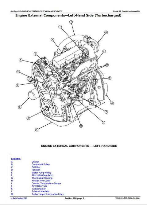
Engine External Components—Left-Hand Side (Turbocharged)
Engine External Components—Right-Hand Side (Turbocharged)
Group 10: Theory of Operation
Theory of Operation Information
Engine Lubrication System Operation––Turbocharged
Engine Cooling System Operation
Group 15: Diagnosis, Tests and Adjustments
Specifications
Essential Tools
Diagnostic Information
Engine Turns Over But Will Not Start or Starts Hard
Engine Runs Irregularly or Stalls Frequently
Engine Runs Rough
Engine Low Power
Engine Smokes—Black or Grey
Engine Smokes Excessively—White
Engine Uses Excess Fuel
Engine Has Excess Noise or Vibration
Engine Uses Excess Oil or Smokes Blue
Engine Has Low Oil Pressure
Engine Coolant Operating Temperature Incorrect
Oil In Coolant or Coolant in Oil
Radiator Bubble Test
Cooling System Test
Radiator Cap Pressure Test
Engine Oil Pressure Test
Cylinder Compression Pressure Test
Fuel Shut-Off Solenoid Check
Throttle Lever Adjustment
In-Line Fuel Injection Pump Setting
Rotary Fuel Injection Pump Timing Adjustment
In- Line Fuel Injection Pump Idle Speed Adjustment
Rotary Fuel Injection Pump Slow Idle Adjustment
Rotary Fuel Injection Pump Fast Idle Adjustment
Valve Clearance Adjustment
Fan/Alternator Drive Belt Adjustment
Bleeding Fuel System – In- Line Pump
Bleed Fuel System at Fuel Injection Nozzles
Bleeding Fuel System – Rotary Pump
Section 230: Fuel/Air Operation, Test and Adjustments
Group 05: Component Location
Component Location Information
Fuel System Components
Air Intake System Components
Group 10: Theory of Operation
Theory of Operation Information
Fuel System Operation
Fuel Filter Operation
Fuel Injection Nozzle Operation
Fuel Injection Pump Fuel Transfer (Feed) Operation – Inline Pump
Fuel Injection Pump Operation––In-Line Pump
Fuel Injection Pump Operation––Rotary Pump
Fuel Injection Pump Governor Operation––In-Line Pump
Air Intake System Operation
Turbocharger Operation––If Equipped
Check Turbocharger Boost Pressure––If Equipped
Diagnosing Turbocharger Malfunctions––If Equipped
Group 15: Diagnosis, Tests and Adjustments
Diagnostic Information
Fuel/Air Diagnosis, Tests and Adjustments
Section 240: Electrical System Operation, Tests and Adjustments
Group 05: Component Location
Component Location Information
Engine Electrical Components—Right Hand Side
Engine Electrical Components—Left Hand Side
Dash And Center Control Console Electrical Components (If Equipped)
Instrument Panel (If Equipped)
Tractor Electrical Components
Group 10: Theory of Operation
Theory of Operation Information
Fuse Block and Fuses
Relays
Starting System Operation—Normal
Starting System Operation—Bypass Attempt
Charging System Operation
Lighting System Operation—Turn Signals And Enhanced Tail Lights
Lighting System Operation—Warning Lights
Lighting System Operation—Tail Lights
Lighting System Operation—Headlights and Instrument Lights
Instrument Panel System Operation—Tachometer/Hour Meter
Instrument Panel System Operation—Fuel Gauge
Instrument Panel System Operation—Temperature Gauge
PTO Warning System Operation
Air Filter Restriction Indicator Operation
7-Pin Trailer Outlet Connector Operation
Horn Operation
Rear Work Light
Group 20: Diagnosis, Test and Adjust
Diagnostic Information
Wire Color Chart
Starting System Test Points—Normal Operation
Starting System Test Points—Bypass Attempt
Charging System Test Points
Lighting System Test Points—Turn Signals And Enhanced Tail Lights
Lighting System Test Points—Warning Lights
Lighting System Test Points—Rear Flood Light
Lighting System Test Points—Headlights and Instrument Lights
Instrument Panel System Test Points—Tachometer/Hourmeter
Instrument Panel System Test Points—Fuel Gauge
Instrument Panel System Test Points—Temperature Gauge
Instrument Panel System Test Points—Oil Pressure
Air Filter Restriction Test Points
Optional Horn Test Points
Accessory Relay and Trailer Connector Test Points
Battery Voltage and Specific Gravity Tests
Charge Battery
Battery Load Test
Starter amp Draw/RPM Test
Starter No-Load amp Draw/RPM Test
Alternator/Regulator Test
Starter Solenoid Test
Starter Relay Test
Key Switch Test
Plug-In Relay Test
Mini Plug-In Relay
Diode Pack Test
Fuse Test
Park Position Start Switch Test
PTO Switch Test
Light Switch Test
Turn Signal Controller Test
Fuel Shut-Off Solenoid Test
Group 25: Wiring Schematics
Schematic Information
Component Identification Table
Electrical Schematic Legend
Electrical Schematic Legend
Section 260: Power Train Operation, Tests and Adjustments
Group 05: Component Location
Component Location Information
Power Train Components
Clutch Components—Dual
Transmission Components—SyncShuttle™
Final Drive Components
Park Brake Components
Rear 540 PTO Components
Rear 540/540E PTO Components––If Equipped
Group 10: Theory of Operation
Theory of Operation Information
Clutch Operation—Dual Clutch
Transmission Lubrication System
SyncShuttle™ Transmission—Gear Shift Power Flow
SyncShuttle™ Transmission Synchronizer Operation—Reverse and 2nd Gear (Disk-and-Plate Type Synchronizer)
SyncShuttle™ Transmission Synchronizer Operation - 1st and 3rd Gear (Cone-Type Synchronizer)
SyncShuttle™ Transmission—Range Shift Power Flow
Mechanical Front Wheel Drive (MFWD) Operation (If Equipped)
Rear 540 PTO Operation
Rear 540/540E PTO Operation––If Equipped
Differential Power Flow
Differential Lock Operation
Final Drive Operation
Group 15: Diagnosis, Tests, and Adjustments
Diagnostic Information
Isolate the Problem Area
Traction Clutch Slips
Traction Clutch Dragging
Traction Clutch Does Not Engage
Traction Clutch Grabs
Traction Clutch Squeaks
Traction Clutch Does Not Release
Traction Clutch Chatters
Traction Clutch Rattles
Traction Clutch Engagement Is Noisy
Excessive Vibration in Traction Clutch
Clutch Pedal Does Not Return
Clutch Pedal Loose
Clutch Pedal Pulsates
Jerky or Rough Transmission of Power
Low Transmission Oil Level (Excessive Oil Leakage)
Gears Clash, Shift Hard, or Will Not Engage
Two Speeds Engage Together
Transmission Will Not Stay in Gear
Transmission Noisy
PTO Noisy
PTO Hard to Engage
PTO Will Not Operate
PTO Will Not Stay Engaged
Excessive Differential Noise
Differential Does Not Work
No Differential Lock
Differential Chatters
Axle Noise
Axle Shaft Will Not Turn
Check and Adjust Clutch Pedal Free Play
PTO Clutch Lever Adjustment
PTO Lever Adjustment Procedure
Section 270: Steering and Brake Operation, Test & Adjustments
Group 05: Component Location
Component Location Information
Steering System Components
Brake System Components
Group 10: Theory of Operation
Theory of Operation Information
Steering System Operation
Steering Valve Operation—Neutral and Manual Turning
Steering Valve Operation—Power Turning
Brake System Operation
Brake Valve Operation
Group 15: Diagnosis, Tests and Adjustments
Diagnostic Information
Isolate the Problem—Steering System
Isolate the Problem—Steering System
Steering Sluggish or Loss of Steering
Isolate the Problem—Brakes
Excessive Brake Pedal Leak-Down
Excessive Brake Chatter
Steering Pump Flow Test
Steering Valve Relief Test
Steering Cylinder Leakage Test
Steering Valve Leakage Test
Checking Toe-In - Two Wheel Drive Tractor
Adjusting Toe-In
Checking Toe - In - MFWD Tractor
Adjusting Toe-In—MFWD Tractor
Brake Pedal Adjustment
Bleed Brake System
Park Brake Band Adjustment
Park Brake Linkage Adjustment
Section 280: Hydraulic System Operation, Test and Adjustments
Group 05: Component Location
Component Location Information
Hydraulic System Components
Group 10: Theory of Operation
Theory of Operation Information
Hydraulic System Operation
Hydraulic Filter Operation
Hydraulic Pump Operation
MITA Rockshaft Control Valve Operation—Park Position
MITA Rockshaft Control Valve Operation—Raise Position
MITA Rockshaft Control Valve Operation—Lower Position
MITA Rockshaft Flow Control Valve Operation (FCV)—Neutral Position
MITA Rockshaft Flow Control Valve Operation (FCV)—Delivery Position
MITA Rockshaft Flow Control Valve Operation (FCV)—Discharge Position
MITA Rockshaft Rate-of-Drop Valve (Implement Lock) Operation
MITA Surge (Safety) Relief Valve Operation
Functioning of Position Control
Functioning of Draft Control
Combined Functioning of Position and Draft Control
MITA Selective Control Valve—Neutral Position
MITA Selective Control Valve—Retract Position
MITA Selective Control Valve—Extend Position
MITA Selective Control Valve—Float Position
EATON Selective Control Valve—Neutral Position
EATON Selective Control Valve—Retract Position
EATON Selective Control Valve—Extend Position
EATON Selective Control Valve—Float Position
Group 15: Diagnosis
Diagnostic Information
Preliminary Hydraulic System Inspection
Entire Hydraulic System Fails to Function/No Hydraulic Pump Output
Insufficient Pump Delivery
Hydraulic Functions Too Slow
Excessive Pump Pressure
Slow Hydraulic Pump Response
Excessive Pump Noise During Operation
Rockshaft Does Not Lift or Lifts Slowly
Rockshaft Does Not Lower or Lowers Slowly
Park Position Unstable, Rockshaft Drops after Engine Shut Down
Group 20: Hydraulic Tests - Without SCV
Hydraulic System Tests
Pump Flow Test
MITA Rockshaft Main Relief Valve Test
JD Rockshaft Main Relief Valve Test
Group 25: Hydraulic Tests—With SCV
Hydraulic System Tests—With SCV
Pump Flow Test—With SCV
Main Relief Valve Test—With SCV
SCV Leakage Test
Group 30: Hydraulic Tests - All
MITA Rockshaft Leakage Test
JD Rockshaft Leakage Test
Rockshaft Lift Cycle Test
Group 35: Adjustments - MITA Rockshaft
Rockshaft Sensing Lever Friction Adjustment
Control of Assembly of Reaction Spring
Measurement Control of Push rod
Adjustment of Position Control Lever
Adjustment Of Draft Control Lever
Group 40: Adjustments - JDRockshaft
Rockshaft Lever Friction Adjustment- JD Rockshaft
Rockshaft Position-Sensing Feedback Linkage Adjustment- JD Rockshaft
Rockshaft Draft-Sensing Feedback Linkage Adjustment- JD Rockshaft
Group 45: Hydraulic Schematics
Hydraulic Circuit Symbols
John Deere Tractors 5055E, 5065E, 5075E Diagnostic and Repair Service Manual (TM901819)
![]()