
John Deere Tractors 5055E, 5065E, 5075E Diagnosis and Tests Service Technical Manual (TM901419)
Complete Diagnosis & Tests Technical Manual with electrical wiring diagrams for John Deere Tractors 5075E, 5065E, 5055E (European), with all the shop information to maintain, diagnose, and service like professional mechanics.
John Deere Tractors 5055E, 5065E & 5075E workshop Diagnosis & Tests technical manual includes:
* Numbered table of contents easy to use so that you can find the information you need fast.
* Detailed sub-steps expand on repair procedure information
* Numbered instructions guide you through every repair procedure step by step.
* Troubleshooting and electrical service procedures are combined with detailed wiring diagrams for ease of use.
* Notes, cautions and warnings throughout each chapter pinpoint critical information.
* Bold figure number help you quickly match illustrations with instructions.
* Detailed illustrations, drawings and photos guide you through every procedure.
* Enlarged inset helps you identify and examine parts in detail.
tm901419 - 5055E, 5065E and 5075E Tractors Diagnostic Technical Manual (European Edition) Technical Manual.pdf
tm901419 - 5055E, 5065E and 5075E Tractors Diagnostic Technical Manual (European Edition) Technical Manual.epub
Total Pages: 1,395 pages
File Format: PDF/EPUB/MOBI/AZW (PC/Mac/Android/Kindle/iPhone/iPad; bookmarked, ToC, Searchable, Printable)
Language: English
MAIN SECTIONS
Foreword
General
Safety
General Specifications
General References
Diagnostic Trouble Codes
CCU Code Diagnostics
ICC Code Diagnostics
PTR Code Diagnostics
Observable Symptoms
Engines
Fuel and Air
Electrical
Control Units
PowrReverser™ Transmissions
Drive Systems
Steering and Brakes
Hydraulics
Operator Station
System Diagnosis
Starting, Charging and Start Aid
PowrReverser™ Transmission
Differential Lock
MFWD
PTO
Steering
Rear Brakes
Rear SCV System Diagnosis
Mid-Mount Control Valve System Diagnosis
Rear Hitch System Diagnosis
Air Conditioning
Engines
General Information
Tests and Adjustments
Engine System Theory of Operation
Fuel and Air
General Information
Fuel and Air Theory of Operation
Electrical System
Fuse/Relay Block
Tests and Adjustments
Theory of Operation
Functional Schematics (Cab)
Functional Schematics (IOOS)
Connector Information
Control Units
General References
Tests and Adjustments
CCU
ICC
PTR
PowrReverser™ Transmission
General Information
Preliminary and Operational Checks
Tests and Adjustments
Theory of Operation
Schematics and Diagrams
TSS Transmission
Tests and Adjustments
Theory of Operation
Schematics and Diagrams
Drive Systems
General Information
Preliminary and Operational Checks
Tests and Adjustments
Theory of Operation
Schematics and Diagrams
Steering and Brakes
General Information
Preliminary and Operational Checks
Test and Adjustments
Theory of Operation
Hydraulics
General Information
Preliminary and Operational Checks
Tests and Adjustments
Theory of Operation
Operator`s Station
General Information
Preliminary and Operational Checks
Tests and Adjustments
Theory of Operation
Service Tools
Dealer-Fabricated Tools
Service Tools and Kits
tm901419 - 5055E, 5065E and 5075E Tractors Diagnostic Technical Manual (European Edition)
Table of Contents
Foreword
Section 210: General
Group 05: Safety
Recognize Safety Information
Understand Signal Words
Follow Safety Instructions
Prepare for Emergencies
Wear Protective Clothing
Protect Against Noise
Handle Fuel Safely—Avoid Fires
Fire Prevention
In Case of Fire
Avoid Static Electricity Risk When Refueling
Use Foldable ROPS and Seat Belt Properly
Stay Clear of Rotating Drivelines
Use Steps and Handholds Correctly
Read Operator’s Manuals for ISOBUS Controllers
Use Seat Belt Properly
Vibration
Operating the Tractor Safely
Avoid Backover Accidents
Limited Use in Forestry Operation
Operating the Loader Tractor Safely
Keep Riders Off Machine
Passenger Seat
Use Safety Lights and Devices
Towing Trailers/Implements Safely (Mass)
Use Caution On Slopes and Uneven Terrain
Freeing a Mired Machine
Avoid Contact with Agricultural Chemicals
Handle Agricultural Chemicals Safely
Handling Batteries Safely
Avoid Heating Near Pressurized Fluid Lines
Remove Paint Before Welding or Heating
Handle Electronic Components and Brackets Safely
Practice Safe Maintenance
Avoid Hot Exhaust
Clean Exhaust Filter Safely
Work In Ventilated Area
Support Machine Properly
Prevent Machine Runaway
Park Machine Safely
Transport Tractor Safely
Service Cooling System Safely
Service Accumulator Systems Safely
Service Tires Safely
Service Front-Wheel Drive Tractor Safely
Tightening Wheel Retaining Bolts/Nuts
Avoid High-Pressure Fluids
Do Not Open High-Pressure Fuel System
Store Attachments Safely
Decommissioning — Proper Recycling and Disposal of Fluids and Components
Group 10: General Specifications
General Specifications
Group 15: General References
Bolt and Cap Screw Torque Values
Glossary of Terms
JIC Hydraulic Symbols
Wiring Diagram and Schematic Information
Electrical Schematic Symbols
Reading Wiring Schematics and Diagrams
Visually Inspect Electrical System
Seven-Step Electrical Procedure
Using a Probe Light
Circuit Types
Circuit Malfunctions
Troubleshooting Circuit Malfunctions
Understanding Electrical vs. Electronic Circuits
Intermittent Electronic Problems
Relay Circuit Types
Using a Digital Multimeter
Troubleshooting Unresolved Problems
Section 211: Diagnostic Trouble Codes
Group CCU: CCU Code Diagnostics
CCU - Non-Tractor CCU Codes
CCU 000096.03 - Fuel Level Sensor Circuit Voltage High
CCU 000096.04 - Fuel Level Sensor Circuit Voltage Low
CCU 000100.01 - Engine Oil Pressure Signal Extremely Low
CCU 000100.04 - Engine Oil Pressure Signal Out of Range Low
CCU 000110.00 - Engine Coolant Temperature Signal Extremely High
CCU 00110.03 - Engine Coolant Temperature Sensor Out of Range High
CCU 00110.04 - Engine Coolant Temperature Sensor Out of Range Low
CCU 000110.16 - Engine Coolant Temperature Signal Moderately High
CCU 000237.02 - VIN Security Data Conflict
CCU 000237.31 - VIN Security Messages Missing
CCU 000569.05 - Rear Differential Lock Solenoid Circuit Fault
CCU 000628.02 - CCU EOL Data Fault
CCU 000630.14 - Rear PTO Configuration Invalid
CCU 001638.00 - Hydraulic Oil Temperature Very Hot
CCU 001638.03 - Hydraulic Oil Temperature Sensor Circuit Voltage High
CCU 001638.04 - Hydraulic Oil Temperature Sensor Circuit Voltage Low
CCU 001638.16 - Hydraulic Oil Temperature High
CCU 001883.00 - Rear PTO Overspeed
CCU 001883.01 - Rear PTO Underspeed
CCU 002818.31 - Operator Presence Switch Not Activated
CCU 003509.03 - Sensor Supply Voltage Out of Range High
CCU 003509.04 - Sensor Supply Voltage Out of Range Low
CCU 523316.04 - CCU Switched Supply Voltage Low
CCU 523839.02 - Secondary Brake Switch Conflict
CCU 523844.12 - Differential Lock Braking Disabled
CCU 523907.02 - PTO Remote Enable Switch Conflict
CCU 523908.02 - Rear PTO External Switch Conflict
CCU 524037.02 - MFWD Switch Circuit Fault
CCU 524223.03 - Differential Lock Circuit Voltage High
CCU 524224.14 - PTO Switch Voltage Mismatch
CCU 524235.05 - MFWD Solenoid Circuit Fault
CCU 524252.05 - Rear PTO Solenoid Circuit Fault
CCU 524255.31 - Rear Remote PTO Enabled
CCU 600006.31 - Default DTC
Group ICC: ICC Code Diagnostics
ICC - Non-Tractor ICC Codes
ICC 000237.02 - ICC VIN Security Mismatch
ICC 000237.31 - ICC VIN Security Missing
ICC 000628.12 - ICC Programming Fault
ICC 000630.02 - ICC Calibration Memory Fault
ICC 002818.31 - Operator Presence Switch Not Activated
Group PTR: PTR Code Diagnostics
PTR 000084.07 - Excessive Wheel Speed Detected During Calibration
PTR 000158.01 - System Switched Voltage Low
PTR 000162.02 - High/Low Switch Circuit Conflict
PTR 000162.31 - High, Low Switch Stuck On
PTR 000190.18 - Engine Speed Missing During Shift
PTR 000191.17 - Top Shaft Speed Too Low
PTR 000598.02 - Clutch Switch Open With Pedal Up
PTR 000598.04 - Clutch Switch Signal Failed Low
PTR 000628.02 - EOL Check Sum Error
PTR 000630.14 - Tractor Model Out Of Range/Transmission Calibration Value High
PTR 000752.03 - Power Shuttle Potentiometer Input Voltage High
PTR 000752.04 - Power Shuttle Potentiometer Input Voltage Low
PTR 001504.10 - Seat Switch Closed Too Long
PTR 002820.31 - Operator Not Present During Shift
PTR 002825.07 - Not Valid Neutral Park Command
PTR 003509.03 - PTR Sensor Supply Voltage High
PTR 003509.04 - PTR Sensor Supply Voltage Low
PTR 521233.05 - High Valve Driver Fault
PTR 521234.05 - Low Valve Driver Fault
PTR 521235.05 - Reverse Valve Driver Fault
PTR 522456.07 - Speed Control Lever Park and Neutral Switch Conflict
PTR 522456.31 - Speed Control Lever Transition Without Using Clutch Pedal
PTR 523953.02 - Speed Control Lever Sensor Circuit Conflict
PTR 523959.31 - No Wheel Speed While in Gear
PTR 524020.31 - Reverser in Gear at Power-Up
PTR 524021.31 - Directional Reverser Lever Switch Circuit Fault
PTR 524160.02 - Not Valid Neutral/Not Neutral Switch
PTR 524173.02 - Clutch Pedal Compare Error
PTR 524173.14 - Sync Lever Shift Without Clutch Pedal Engaged
PTR 524173.15 - Clutch Pedal Voltage High
PTR 524173.16 - Both Clutch Pedals Voltage High
PTR 524173.17 - Clutch Pedal Voltage Low
PTR 524173.18 - Both Clutch Pedals Voltage Low
PTR 524230.05 - Enable Valve Driver Fault
PTR 524230.07 - Enable Valve Stuck
PTR 524234.03 - Pressure Sensor Voltage High
PTR 524234.04 - Pressure Sensor Voltage Low
PTR 524254.03 - Transmission Enable Valve Power High
PTR 524254.04 - Transmission Enable Valve Power Low
PTR 524267.15 - High Speed Shuttle Shift
Section 212: Observable Symptoms
Group 20: Engines
Engine Problems
Group 30: Fuel and Air
Fuel and Air Problems
Group 40: Electrical
12-Volt Electrical Problems
Group 45: Control Units
Electronic Problems
Group 55: PowrReverser™ Transmissions
PowrReverser™ Transmission Problems
Group 56: Drive Systems
Drive System Problems
Group 60: Steering and Brakes
Steering and Brake System Problems
Group 70: Hydraulics
Hitch Problems
Selective Control Valve Problems
Group 90: Operator Station
Air Conditioning Problems
Section 213: System Diagnosis
Group 40: Starting, Charging and Start Aid
Starting, Charging and Start Aid System Diagnosis
Group 55: PowrReverser™ Transmission
PowrReverser™ Transmission System Diagnosis
Group 56A: Differential Lock
Differential Lock System Diagnosis
Group 56B: MFWD
MFWD System Diagnosis
Group 56C: PTO
Rear Mechanical PTO System Diagnosis
EH PTO System Diagnosis
Group 60A: Steering
Steering System Diagnosis
Group 60B: Rear Brakes
Rear Brake System Diagnosis
Group 70A: Rear SCV System Diagnosis
Single and Dual Rear SCV System Diagnosis
Group 70B: Mid-Mount Control Valve System Diagnosis
Dual Mid-Mount Control Valve System Diagnosis
Group 70C: Rear Hitch System Diagnosis
Rear Mechanical Hitch System Diagnosis
EQRL Hitch System Diagnosis
Group 90: Air Conditioning
Air Conditioning System Diagnosis
Section 220: Engines
Group 05: General Information
John Deere Engine Repair—Use Component Technical Manual
General Engine Specifications
List of All Tractor-Specific Engine Information
Group 15: Tests and Adjustments
Throttle Lever Adjustment—Cab
Group 20: Engine System Theory of Operation
Overview of 5055E , 5065E , and 5075E Tractor Engines
Section 230: Fuel and Air
Group 05: General Information
John Deere Engine Fuel Systems Repair—Use Component Technical Manual
Group 20: Fuel and Air Theory of Operation
Fuel System Operation— 5055E, 5065E and 5075E
Air Intake System Operation
Section 240: Electrical System
Group 05: Fuse/Relay Block
Fuse/Relay Block Diagram Listing
Access Fuses and Relays
Load Center Fuses and Relays—Cab (sync shuttle Transmission)
Center Console Relay and Diode—Cab (sync shuttle Transmission)
Load Center Fuses and Relays—Cab (PowrReverser™ Transmission)
Center Console Relay and Diode—Cab (PowrReverser™ Transmission)
EEC Light Module Relays—Cab (PowrReverser™ Transmission)
Light Module Relay—Cab
Load Center - 1 Fuses and Relays—IOOS (PowrReverser™ Transmission)
Load Center - 2 Fuses and Relays—IOOS— (PowrReverser™ Transmission)
Center Console Relay and Diode—IOOS (PowrReverser™ Transmission)
Group 15: Tests and Adjustments
Starting Circuit Test
Fuel Shutoff Solenoid Circuit Test
Battery Inspection Test
Charging System Test
Warning Lights Circuit Test
Turn Signal Lights Circuit Test
Brake Lights Circuit Test
Accessory Power and Junction Block Circuit Test
Engine Speed Sensor Circuit Test
Engine Oil Pressure Switch Circuit Test
Air Filter Restriction Switch Circuit Test
Fuel Level Sender Circuit Test
Engine Coolant Temperature Sender Circuit Test
Tail Light Circuit Test
Front Work Light Circuit Test
Beacon Light Circuit Test
Rear Work Light Circuit Test
Headlight and Backlighting Circuit Test
Radio and Dome Light Circuit Test
HVAC Circuit Test
Wiper System Circuit Test
Key Switch Test
Switch Test
Fuel Transfer Pump Circuit Test
Group 20: Theory of Operation
Starting System Operation
Cold Start System Operation
Charging System Operation
Lighting System Operation—Turn Signals
Lighting System Operation—Warning Lights
Lighting System Operation—Tail Lights
Lighting System Operation—Headlights and Loader Lights
Work Light and Beacon Light Operation
Instrument Cluster Operation—Tachometer/Hour Meter
Instrument Cluster Operation—Fuel Gauge
Instrument Cluster Operation—Coolant Temperature Gauge
PTO Warning System Operation
Air Filter Restriction Indicator Operation
Accessory Power and Junction Block Power Operation
Blower Motor Operation
Front Wiper/Washer Operation
Rear Wiper/Washer Operation
Dome Light Operation
Wheel Speed Sensor Operation
Group 25: Functional Schematics (Cab)
Functional Schematics Listing (Cab)
Schematic and Component Identification Legend (Cab)
SE1—Key Switch, Starter, Alternator, Starting Aid And Fuel Pump Circuit
SE2A—Mechanical PTO, Neutral Start, Fuel Circuit (9/3 TSS), SE2B—EH PTO, Neutral Start, Fuel Circuit (12/12 PR), SE3—Accessory Power, SE4—Horn
SE7—Common Vehicle Lighting Section, Common Cab Work Lighting
SE8—Turn Signal Switch and Hazard Warning Lights
SE9—Power Source, SE11—Trailer Interfaces, SE12—Loader Lights , SE13A—Backup Alarm, SE13B—Beacon Lamp
SE15B—Power Outlet, SE16—Heater, SE17—Air Conditioning
SE20—Front Windshield Wiper And Washer System, SE21—Rear Windshield Wiper And Washer System, SE22—Dome Light, Door Switch And Radio Option, SE23—Air Seat Option
SE24A—Instrumentation (PR), SE24B—Instrumentation (TSS)
SE25—Seat Switch, Rear PTO Switch, SE26—ELX Relay And Fuses, SE27—MFWD, SE28—Brake Switch
SE29—PR Transmission Controller
SE30—EQRL Controller (PR)
SE32—CAN Terminators (PR)
Group 26: Functional Schematics (IOOS)
Functional Schematics Listing (IOOS)
Schematic and Component Identification Legend (IOOS)
SE01— Key Switch, Starter and Alternator
SE02— Light Circuit
SE03— Instrument Cluster
SE04— Transmission Controller
SE05— Transmission Controller and Service ADVISOR™ Unit
SE06— Trailer Circuit, Horn and Seat Switch
Group 30: Wiring Harnesses (Cab)
Wiring Harnesses Schematic Listing
Engine Wiring Harness
Hood Wiring Harness
Cab Wiring Harness
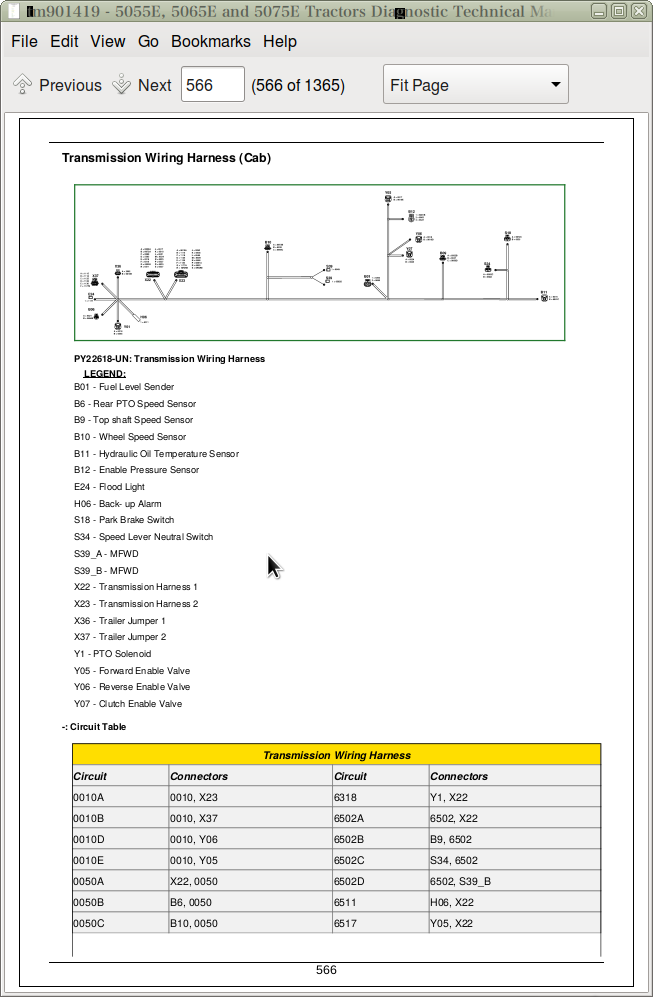
Transmission Wiring Harness (Cab)
Rear Wiring Harness
Wiring Harness Module EEC
Roof Wiring Harness
Group 30A: Wiring Harnesses (IOOS)
Wiring Harnesses Schematic Listing
Hood Wiring Harness
Transmission Wiring Harness (IOOS)
Front Wiring Harness
Alternator Supply Wiring Harness
Beacon Lamp Wiring Harness
Console PR Wiring Harness
Group 35: Connector Information
Front Console-to-Cab Harness Connector 1
Front Console-to-Cab Harness Connector 2
Front Console-to-Cab Harness Connector 3
Roof Harness-to-Cab Harness Connector 1
Roof Harness-to-Cab Harness Connector 2
Section 245: Control Units
Group 05: General References
Electro-Hydraulic Controller General Information
Performance Monitor General Operation
Recall, Record, and Clear Codes
Diagnostic Trouble Code Listing
CCU Code List
ICC Code List
PTR Code List
Control Unit Addresses
CCU Address List
ICC Address List
PTR Address List
Programming Control Units
CAN Network Voltage Checks
CAN Communication System Theory of Operation
CAN System Diagnosis
VIN Security Fault Diagnosis
Group 15: Tests and Adjustments
Electro-Hydraulic Controller Switched Supply Voltage and Ground Test
Electro-Hydraulic Controller Unswitched Supply Voltage and Ground Test
Open Circuit Load Test
EHC—Electrohydraulic Control Unit Test
ICC—Instrument Cluster Control Unit Test
Group CCU: CCU
Chassis Control Unit (CCU) Calibration
Chassis Control Unit (CCU) Configuration and Calibration
CCU—Hydraulic Oil Temperature Sensor Circuit Test (PR Transmission)
CCU—MFWD Solenoid Circuit Test (PR Transmission)
CCU—Sensor Excitation Circuit Test (PR Transmission)
CCU—Rear PTO Solenoid Circuit Test (PR Transmission)
CCU—Rear PTO Speed Sensor Circuit Test (PR Transmission)
CCU—Secondary Brake Switch Circuit Test (PR Transmission)
CCU—Differential Lock Switch Circuit Test (PR Transmission)
CCU—Differential Lock Solenoid Circuit Test (PR Transmission)
CCU—Fuel Level Sensor Circuit Test (PR Transmission)
CCU—Remote PTO Enable Switch Circuit Test (PR Transmission)
CCU—Right Fender PTO ON/OFF Switch Circuit Test (PR Transmission)
CCU—Left Fender PTO ON/OFF Switch Circuit Test (PR Transmission)
CCU 000 — Initial Address
CCU 001 — Recall Diagnostic Codes
CCU 002 — System Beep Address With Speed Sensors
CCU 003 — System Beep Address Without Speed Sensors
CCU 004 — Switched Supply Voltage
CCU 005 — Rear PTO Speed Signal Status
CCU 006 — Primary Wheel Speed Signal Status
CCU 007 — Rear PTO Switch Status
CCU 008 — Engine Speed Signal Status
CCU 010 — Hydraulic Oil Temperature Sensor Voltage
CCU 012 — Rear PTO Remote Enable/Remote Fender Switch Status
CCU 013 — Primary Fuel Level Sensor Voltage
CCU 014 — Primary Fuel Level Sensor Resistance
CCU 015 — Sensor Reference Voltage Status
CCU 024 — Secondary Hand Brake/Brake Pedal Switch Status
CCU 025 — MFWD Switch Status
CCU 050 — CCU Unswitched Supply Voltage
CCU 051 — Sensor Reference Voltage
CCU 052 — Hydraulic Oil Temperature
CCU 054 — Fuel Level Percent
CCU 055 — Primary Wheel Speed
CCU 058 — Rear PTO Speed
CCU 059 — Engine Speed
CCU 060 — Front PTO Speed
CCU 063 — Differential Drive Shaft Speed
CCU 064 — Engine Oil Pressure Switch Status
CCU 065 — Engine Coolant Temperature
CCU 066 — Engine Coolant Temperature Sensor Voltage
CCU 102 — Fuel Sensor Setup
CCU 103 — MFWD Configuration
CCU 104 — Rear PTO Configuration 1
CCU 105 — Rear PTO Configuration 2
CCU 106 — Rear PTO Speed Configuration
CCU 107 — Rear PTO Pulses Per Revolution
CCU 108 — Front PTO Pulses Per Revolution
CCU 109 —Front PTO Installed
CCU 111 — Rear Tire Rolling Circumference
CCU 115 — Differential Lock Configuration
CCU 116 — Differential Lock Switch
CCU 117 — Differential Lock Disengage Wheel Speed Configuration
CCU 120 — Rear PTO Valve Current
CCU 129 — MFWD Engaged with Battery Input
CCU 130 — Secondary Handbrake Configuration
CCU 134 — Engine Hours Display/Input
CCU 135 — Engine Function Configuration
CCU 180 — Not Used
CCU 200-251 — General Control Unit Data
CCU - Beep Mode Test With Speed Sensors
CCU - Beep Mode Test Without Speed Sensors
CCU - Hydraulic Oil Temperature Sensor Circuit Test
CCU - Engine Speed Sensor Circuit Test
CCU - Wheel Speed Sensor Circuit Test
CCU - Controller Theory of Operation
CCU - Hydraulic Oil Temperature Sensor Theory of Operation
CCU - Engine Speed Sensor Theory of Operation
CCU - Wheel Speed Sensor Theory of Operation
Group ICC: ICC
Instrument Cluster Control Unit (ICC) Configuration and Calibration
ICC 000 — Initial Address
ICC 001 — Recall Diagnostic Codes
ICC 002 — ICU System Beep Address
ICC 005 — Switch Status
ICC 006 — Indicator Status
ICC 010 — Fuel Level Sender Voltage
ICC 020 — Units Selection
ICC 021 — Auto Clear DTC Hours
ICC 022 — Backlight Dimming Percentage
ICC 031 — Revert to Hours Status
ICC 032 — ICC Flash Rate 1
ICC 033 — ICC Flash Rate 2
ICC 036 — Engine Coolant Warning Level
ICC 037 — Engine Coolant Stop Level
ICC 040 — Fuel Gauge Configuration
ICC 041 — Resistance Verses Fuel Level Gauge Constant 1
ICC 042 — Resistance Verses Fuel Level Gauge Constant 2
ICC 043 — Resistance Verses Fuel Level Gauge Constant 3
ICC 044 — Resistance Verses Fuel Level Gauge Constant 4
ICC 045 — Resistance Verses Fuel Level Gauge Constant 5
ICC 046 — Resistance Verses Fuel Level Gauge Constant 6
ICC 047 — Resistance Verses Fuel Level Gauge Constant 7
ICC 048 — Resistance Verses Fuel Level Gauge Constant 8
ICC 049 — Resistance Verses Fuel Level Gauge Constant 9
ICC 200-248 — General Control Unit Data
Group PTR: PTR
Power Train Reverser (PTR) Control Unit Calibration
Power Train Reverser (PTR) Control Unit Configuration and Calibration
PTR—Clutch Enable Pressure Sensor Circuit Test
PTR—Clutch Enable Solenoid Circuit Test
PTR—Clutch Pedal Position Circuit Test
PTR—Clutch Pedal Switch Circuit Test
PTR—Forward Neutral Reverse (FNR) Switch Circuit Test
PTR—High/Low Shifter Switch Circuit Test
PTR—Park Switch Circuit Test
PTR—Power Shuttle Control Circuit Test
PTR—Start Signal Circuit Test
PTR—Top Shaft Speed Sensor Circuit Test
PTR—Transmission Forward Solenoid Circuit Test (High)
PTR—Transmission Forward Solenoid Circuit Test (Low)
PTR—Transmission Reverse Solenoid Circuit Test
PTR—Speed Lever Neutral Switch Circuit Test
PTR 000 — Initial Address
PTR 001 — Recall Diagnostic Codes
PTR 002 — PTR System Beep Mode
PTR 003 — PTR System Beep Mode With Speed Sensors
PTR 004 — Engine and Countershaft Speed Sensor Status
PTR 005 — Come Home, Trans Enable, Clutch Pedal Switch, and Seat Switch Status
PTR 006 — Forward, Neutral, Not Neutral, and Reverse Switch Status
PTR 007 — Speed Lever Neutral, High, Low, and Park Switch Status
PTR 008 — Trans Enable Relay, High, Low, and Reverse Driver Command
PTR 009 — High, Low, and Reverse Driver Status
PTR 010 — Trans Enable Solenoid Current
PTR 011 — Power Shuttle Input Voltage
PTR 012 — Trans Enable Pressure Sensor Voltage
PTR 013 — Clutch Pedal Potentiometer Channel A Voltage
PTR 014 — Clutch Pedal Potentiometer Channel B Voltage
PTR 015 — Creeper Lever Position Sensor Voltage
PTR 022 — Clutch Pack Overfill Protection Status
PTR 032 — Clutch Pedal Position
PTR 033 — Clutch Pedal Pressure Command
PTR 034 — Trans Enable Actual Pressure
PTR 036 — Countershaft Speed
PTR 050 — PTR Switched Supply Voltage
PTR 051 — PTR Sensor Supply Voltage
PTR 052 — Hydraulic Oil Temperature
PTR 060 — Transmission Type
PTR 061 — Hydraulic Oil Type Selection
PTR 062 — Temperature Offset For Alternate Hydraulic Oil
PTR 063 — Transmission Calibration
PTR 064 — Transmission Fill Pressure and Fill Time Calibration Values
PTR 065 — Forward Valve High Fill Pressure Adjustment
PTR 066 — Forward Valve High Fill Time Adjustment
PTR 067 — Forward Valve Low Fill Pressure Adjustment
PTR 068 — Forward Valve Low Fill Time Adjustment
PTR 069 — Reverse Valve Fill Pressure Adjustment
PTR 070 — Reverse Valve Fill Time Adjustment
PTR 072 — Has Calibration been Completed
PTR 075 — PTR PowerShuttle Setup Status
PTR 076 — PowerShuttle Minimum Wheel Speed Fill Pressure
PTR 077 — PowerShuttle Minimum Wheel Speed
PTR 078 — PowerShuttle Pressure Offset
PTR 079 — High Speed Shuttle Shift Limit
PTR 084 — Engine Brake Torque
PTR 086 — Hi/Lo Switch Setup
PTR 087 — Park Switch Polarity
PTR 088 — Seat Switch Polarity
PTR 100 — Come Home Mode Enable
PTR 101 — Come Home Mode Relay Block Polarity
PTR 200-251 — General Control Unit Data
PTR - Control Unit Beep Mode Test With Speed Sensors
PTR - Control Unit Beep Mode Test Without Speed Sensors
PTR - Directional Reverser Switch Circuit Test
PTR - Clutch Disengaged Switch Circuit Test
PTR - Optional Infinitely Variable Shuttle Control Circuit Test
PTR - Park Switch Circuit Test
PTR - Seat Switch Circuit Test
PTR - Forward Solenoid Circuit Test
PTR - Reverse Solenoid Circuit Test
PTR - Clutch Enable Proportional Valve Circuit Test
PTR - Clutch Pedal Position Sensor Circuit Test
PTR - Enable Pressure Sensor Circuit Test
PTR - Countershaft Speed Sensor Circuit Test
PTR - Control Unit Theory of Operation
PTR - Directional Reverser Switch Theory of Operation
PTR - Clutch Disengaged Switch Theory of Operation
PTR - Optional Infinitely Variable Shuttle Control Theory of Operation
PTR - Park Switch Theory of Operation
PTR - Seat Switch Theory of Operation
PTR - Forward Solenoid Theory of Operation
PTR - Reverse Solenoid Theory of Operation
PTR - Clutch Enable Proportional Valve Theory of Operation
PTR - Clutch Pedal Position Sensor Theory of Operation
PTR - Enable Pressure Sensor Theory of Operation
PTR - Countershaft Speed Sensor Theory of Operation
Section 255A: PowrReverser™ Transmission
Group 05: General Information
PowrReverser™ Transmission Identification
Install Test Equipment - Transmission
Group 10: Preliminary and Operational Checks
PR Transmission Preliminary Checks
PR Transmission Operational Checks
Group 15: Tests and Adjustments
PowrReverser™ Control Valve Tests
PR Pump Flow Test
PR Main Pressure Relief Valve Adjustment
Transmission System Pressure Test
PTO Clutch Leak Test
Checking and Adjusting Clutch Pedal Free Play
Group 20: Theory of Operation
PowrReverser™ Transmission Theory of Operation
Group 25: Schematics and Diagrams
PowrReverser™ Transmission Component Location Listing
PR Transmission Hydraulic Schematic
Power Train Components
PowrReverser™ Components
Transmission Components
Section 255B: TSS Transmission
Group 15: Tests and Adjustments
Checking and Adjusting Clutch Pedal Free Play
Group 20: Theory of Operation
TSS Transmission Theory of Operation
Group 25: Schematics and Diagrams
Component Location Information
Transmission Components (TSS)
Mechanical PTO Clutch Components
Park Brake Components (TSS Transmission)
Rear PTO Components
Rear 540/540E PTO Components
Section 256: Drive Systems
Group 05: General Information
Install Test Equipment - Drive System
Group 10: Preliminary and Operational Checks
Preliminary Checks - Drive System
Rear Differential Lock Operational Check
PTO Operational Checks
MFWD Operational Checks
Group 15: Tests and Adjustments
MFWD Troubleshooting
PTO Clutch Lever Linkage Adjustment
PTO 540/540E Lever and Linkage Adjustment
Group 20: Theory of Operation
Drive Systems Theory of Operation Reference Listing
Differential Power Flow
Rear Differential Lock Operation
Final Drive Operation
Mechanical Front Wheel Drive (MFWD) Drop Gearbox Operation (Mechanical)
Mechanical PTO Operation
540/540E Mechanical PTO Operation
Electro-Hydraulic PTO Operation
Electro-Hydraulic PTO Valve Operation
Electro-Hydraulic PTO Clutch Operation
Group 25: Schematics and Diagrams
Drive Systems Component Location Listing
Final Drive Components
540/540E Mechanical PTO Components
Section 260: Steering and Brakes
Group 05: General Information
Install Test Equipment - Steering and Brake
Group 10: Preliminary and Operational Checks
Steering Preliminary Check
Steering Operational Check
Rear Brakes Preliminary Check
Rear Brake Operational Test
Group 15: Test and Adjustments
Steering Pump Flow Test
Steering Valve Relief Test
Steering Leak Test
Checking Toe-In—MFWD Axle
Adjusting Toe-In—MFWD Axle
Set MFWD Steering Stops Turning Radius
Bleed Rear Brakes
Rear Brake Valve Leak Test
Brake Pedal Adjustment
Adjust Brake Retractors
Group 20: Theory of Operation
Steering Valve Operation—Park Position and Manual Turning
Steering Valve Operation—Power Turning
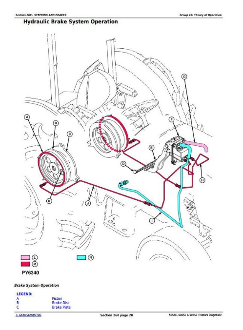
Hydraulic Brake System Operation
Brake Valve Operation
Section 270: Hydraulics
Group 05: General Information
Install Test Equipment - Hydraulics
Warming Transmission/Hydraulic System Oil
Group 10: Preliminary and Operational Checks
Hydraulic System Preliminary Checks
Hydraulic System Operational Checks
Group 15: Tests and Adjustments
Pump Flow Test (Tractors With SCV)
Main Relief Valve Test (Tractors With SCV)
SCV Leakage Test
Rockshaft Leakage Test
Rockshaft Lift Cycle Test
Mid-Mount Control Valve Cable Adjustment
Rear SCV Cable Adjustment
Rockshaft Position-Sensing Feedback Linkage Adjustment
Rockshaft Draft-Sensing Feedback Linkage Adjustment
Rockshaft Lever Friction Adjustment
Hitch Limit Adjustment for EQRL (If Equipped)
Group 20: Theory of Operation
Hydraulic System Theory of Operation Information Reference Listing
Hydraulic System Operation
Hydraulic Filter Operation
Hydraulic Pump Operation
Rockshaft Control Valve Operation—Neutral Phase
Rockshaft Control Valve Operation—Delivery Phase
Rockshaft Control Valve Operation—Discharge Phase
Main Relief Valve Operation
Rate-of-Drop Valve Operation
Surge Relief Valve Operation
Rockshaft Draft-Sensing Operation
Selective Control Valve—Neutral Position
Selective Control Valve—Retract Position
Selective Control Valve—Extend Position
Selective Control Valve—Float Position
Dual Mid-Mount Control Valve Operation—Neutral Position
Dual Mid-Mount Control Valve Operation—Extend and Retract Positions
Dual Mid-Mount Control Valve Operation—Float Position
Dual Mid-Mount Control Valve Operation—Regenerative Position
Quick Disconnect Coupler Operation (Mid-Mount Control Valve)
Quick Disconnect Coupler Operation (Rear SCV)
Section 290: Operator's Station
Group 05: General Information
Operator Station— Install Test Equipment
Group 10: Preliminary and Operational Checks
A/C System Preliminary Checks
Air Conditioning Operational Checks
Group 15: Tests and Adjustments
HVAC Circulation Blower Motor Circuit Test
HVAC Compressor Clutch Engagement and Cycle Test
HVAC System Pressure Check
HVAC Temperature Drop Check
Summary of A/C Testing
A/C System Moisture Removal Procedure
Adjust Heater Temperature Control Cable
Adjust A/C Temperature Control Switch
Group 20: Theory of Operation
Air Conditioning Theory of Operation
Section 299: Service Tools
Group 05: Dealer-Fabricated Tools
DFRW26—Test Lead for Automotive-Style Fuses
DFRW51—Electronic Circuit Load Tester
DFRW126—Modified Tap Out Harness
DFRW133—Tap Out Harness
Group 10: Service Tools and Kits
AR94522—ISO SCV Coupler
JDG774—Solenoid Test Harness
JT02051—Manifold with Gauges
JT02081—Halogen Leak Detector
JT02153—Current Clamp-On Probe
JT03043—Adapter 1/2 M NPT x 1-1/16 M 37°
JT03044—Adapter 3/4 M NPT x 1-1/16 M 37°
JT03051—Adapter 1-1/16 F 37° x 1-1/16 F 37°
JT03059—90° Elbow, 1 1/16-12 M 37° x 1 1/16-12 F 37° Sw
JT03110—Adapter
JT03262—Adapter
JT03345—Gauge
JT03364—Hose with Coupler
JT03367—Connector
JT03481—Kit
JT03481-1—Adapter Male Quick Coupler Plug x 1/4 M NPT
JT03481-3—Straight Fitting 3/4-14 F NPT x M20 x 1.5 ORB
JT03481-4—Straight Fitting 1/8 M BSPT X 1/8 F NPT
JT03520—Special Adapter
JT05473—Gauge w/Quick Coupler, 0-35,000 kPa (0-5000 psi)
JT05494—7/16-20 M 37° x 3/4-16 M ORB
JT05498—Hose 508 mm (20 in.)
JT05634—Pressure Gauge
JT05685—Battery Load Tester
JT05690—1 1/16-12 M 37° x 1 3/16-12 F ORFS
JT05791—Digital Multimeter
JT05843—Hydrometer
JT07032—Gauge 400 kPa (60 psi)
JT07041—Gauge 2800 kPa (400 psi)
JT07148—Digital Hydraulic Tester
JDG10466
JDG1478
John Deere Tractors 5055E, 5065E, 5075E Diagnosis and Tests Service Technical Manual (TM901419)
![]()