
John Deere Tractors 5055E, 5065E, 5075E, 5078E, 5085E, 5090E Diagnosis and Tests Service Technical Manual (TM801619)
Complete Diagnosis & Tests Technical Manual with electrical wiring diagrams for John Deere Tractors 5090E, 5085E, 5078E, 5075E, 5065E, 5055E (2WD or MFWD - PIN Prefix BM), with all the technical information to maintain, diagnose, and test like professional mechanics.
John Deere Tractors 5055E, 5065E, 5075E, 5078E, 5085E, 5090E workshop Diagnosis & Tests technical manual includes:
* Numbered table of contents easy to use so that you can find the information you need fast.
* Detailed sub-steps expand on repair procedure information
* Numbered instructions guide you through every repair procedure step by step.
* Troubleshooting and electrical service procedures are combined with detailed wiring diagrams for ease of use.
* Notes, cautions and warnings throughout each chapter pinpoint critical information.
* Bold figure number help you quickly match illustrations with instructions.
* Detailed illustrations, drawings and photos guide you through every procedure.
* Enlarged inset helps you identify and examine parts in detail.
tm801619 - 5055E, 5065E, 5075E, 5078E, 5085E and 5090E Tractors — Diagnostics Technical Manual - (World Edition) Technical Manual.pdf
tm801619 - 5055E, 5065E, 5075E, 5078E, 5085E and 5090E Tractors — Diagnostics Technical Manual - (World Edition) Technical Manual.epub
Total Pages: 1,602 pages
File Format: PDF/EPUB/MOBI/AZW (PC/Mac/Android/Kindle/iPhone/iPad; bookmarked, ToC, Searchable, Printable)
Language: English
MAIN SECTIONS
Foreword
General Information
Safety
General References
References for Technical Information
Observable Symptoms and System Diagnostics
Engine
Fuel and Air Intake
Electrical System - 5055E and 5065E
Electrical System - 5075E
Electrical System - 5078E, 5085E and 5090E - Open Operator's Platform
Electrical System - 5078E, 5085E and 5090E - Cab
Drive Train
Steering and Brakes
Hydraulic System
Cab
Engine
General Information
Theory of Operation
Diagram
Tests for Diagnostics and Adjustments
Information on Engine Components
General Information
Engine Components
Fuel System, Air Intake, Cooling and Exhaust Systems
General Information
Theory of Operation
Schematic
Tests for Diagnostics and Adjustments
Fuel System, Cooling, Air Intake and Exhaust System Component Information
General Information
Fuel System Components
Air Intake System Components
Cooling System Components
Electrical System - 5055E and 5065E
General Information
Operational and Preliminary Checks
Theory of Operation
Schematic
Diagnostic Tests and Adjustments
Electrical System - 5075E
General Information
Operational and Preliminary Checks
Identification of Type
Theory of Operation
Schematic
Diagnostic Tests and Adjustments
Electrical System - 5078E, 5085E and 5090E - Open Operator's Platform
General Information
Operational and Preliminary Checks
Theory of Operation
Schematic
Diagnostic Tests and Adjustments
Electrical System - 5078E, 5085E and 5090E - Cab
General Information
Operational and Preliminary Checks
Theory of Operation
Schematic
Diagnostic Tests and Adjustments
Information on Electrical Components - 5055E and 5065E
Wiring Harnesses
Connectors
Information on Electrical Components - 5075E
Wiring Harnesses
Connectors
Information on Electrical Components - 5078E, 5085E and 5090E - Open Operator's Platform
Wiring Harnesses
Connectors
Electrical Components Information - 5078E, 5085E and 5090E - Cab Tractors
Wiring Harnesses
Connectors
Drive Train
General Information
Theory of Operation
Tests for Diagnostics and Adjustments
Drive Train Components Information
General Information
Drive Train Components
Steering and Brakes
General Information
Theory of Operation
Tests for Diagnostics and Adjustments
Steering and Brake Components Information
Steering System Components
Brake Components
Hydraulic System
General Information
Operational and Preliminary Checks
Identification of Type
Theory of Operation - A-Type
Theory of Operation - B-Type
Theory of Operation - Type C
Theory of Operation - Type D
Hydraulic Schematics
Diagnostic Tests and Adjustments-A-Type
Diagnostic Tests and Adjustments-B-Type
Diagnostic Tests and Adjustments-C-Type
Diagnostic Tests and Adjustments-D-Type
Information on Hydraulic Components
Hydraulic Components
Cab
General Information
Operational and Preliminary Checks
Theory of Operations
Schematic
Diagnostic Tests and Adjustments
Information on Cab Components
Cab Components
tm801619 - 5055E, 5065E, 5075E, 5078E, 5085E and 5090E Tractors — Diagnostic Technical Manual -: (World Edition)
Table of Contents
Foreword
Section 210: General Information
Group 05A: Safety
Recognize Safety Information
Understand Signal Words
Follow Safety Instructions
Prevent Machine Runaway
Handle Fluids Safely—Avoid Fires
Prevent Battery Explosions
Prepare for Emergencies
Handling Batteries Safely
Service Cooling System Safely
Handle Chemical Products Safely
Park Machine Safely
Support Machine Properly
Wear Protective Clothing
Work in Clean Area
Service Machines Safely
Work In Ventilated Area
Illuminate Work Area Safely
Replace Safety Signs
Use Proper Lifting Equipment
Wait Before Opening High-Pressure Fuel System
Avoid High-Pressure Fluids
Use Steps and Handholds Correctly
Remove Paint Before Welding or Heating
Avoid Heating Near Pressurized Fluid Lines
Keep ROPS Installed Properly
Service Tires Safely
Avoid Harmful Asbestos Dust
Practice Safe Maintenance
Use Proper Tools
Dispose of Waste Properly
Live With Safety
Group 05B: General References
Summary of References
Information Available in Sections, Groups and Subgroups
Trademarks
Basic Diagnostic Philosophy
Regions and Countries
Glossary of Terms
Group 05C: References for Technical Information
Metric Bolt and Screw Torque Values
Unified Inch Bolt and Screw Torque Values
Face Seal Fittings Assembly and Installation—All Pressure Applications
Metric Face Seal and O-Ring Stud End Fitting Torque Chart—Standard Pressures
Metric Face Seal and O-Ring Stud End Fitting Torque Chart—High Pressure Applications
SAE Face Seal and O-Ring Stud End Fitting Torque Chart—Standard Pressures
SAE Face Seal and O-Ring Stud End Fitting Torque Chart—High Pressure Applications
Four Bolt Flange Fittings Assembly and Installation—All Pressure Applications
SAE Four Bolt Flange Cap Screw Torque Values—Standard Pressure Applications
SAE Four Bolt Flange Cap Screw Torque Values—High Pressure Applications
External Hexagon Port Plug Torque Chart
Section 212: Observable Symptoms and System Diagnostics
Group 20: Engine
Engine Problems
Group 30: Fuel and Air Intake
Problems in Fuel System, Air Intake, Cooling and Exhaust Systems
Group 40A: Electrical System - 5055E and 5065E
Electrical System Problems - 5055E and 5065E
Group 40B: Electrical System - 5075E
Electrical System Problems - 5075E
Group 40C: Electrical System - 5078E, 5085E and 5090E - Open Operator's Platform
Electrical System Problems - 5078E, 5085E and 5090E - Open Operator's Platform
Group 40D: Electrical System - 5078E, 5085E and 5090E - Cab
Electrical System Problems - 5078E, 5085E and 5090E - Cab
Group 50: Drive Train
Drive Train Problems
Group 60: Steering and Brakes
Steering and Brake Problems
Group 70: Hydraulic System
Hydraulic System Problems
Group 90: Cab
Heating, Ventilation and Air Conditioning Problems
Section 220: Engine
Group 05: General Information
Summary of References
Group 20: Theory of Operation
Operation of Engine Lubricating System
Operation of Engine Lubricating System—Continuation
Group 30: Diagram
Engine Lubrication System
Group 50: Tests for Diagnostics and Adjustments
Diagnostic Information
Specifications
Essential Tools
Engine Does Not Start
Engine Operating Irregularly or Stalling Frequently
Engine Operating Irregularly
Low Engine Power
Engine Emits Smoke - Black or Gray
Engine Emits Excessive Smoke - White
Engine with Excessive Fuel Usage
Engine with Noise or Excessive Vibration
Engine with Excessive Oil Usage or Blue Smoke
Engine with Low Oil Pressure
Incorrect Operating Temperature of Engine Coolant
Oil in Coolant or Coolant in Oil
Radiator Bubble Test
Cooling System Test
Radiator Cap Pressure Test
Engine Oil Pressure Test
Cylinder Compression Pressure Test
Throttle Lever Adjustment
Adjusting Idle Speed
Adjusting Injection Pump Synchronization
Check and Adjust Valve Play—4-Cylinder Engine
Adjusting Valve Play—3-Cylinder Engine
Fan/Alternator Drive Belt Adjustment
Bleeding Fuel System
Bleeding Fuel System at Injection Nozzles
Checking Turbocharger Auxiliary Pressure
Turbocharger Defect Diagnostics
Section 229: Information on Engine Components
Group 05: General Information
Component Location Information
Group 40: Engine Components
External Components of 3-Cylinder Engine—Left-Hand Side
External Components of 3-Cylinder Engine—Right-Hand Side
External Components of 4-Cylinder Engine—Left-Hand Side
External Components of 4-Cylinder Engine—Right-Hand Side
Section 230: Fuel System, Air Intake, Cooling and Exhaust Systems
Group 05: General Information
Summary of References
Group 20: Theory of Operation
Cooling System Operation—3-Cylinder Engine
Cooling System Operation—4-Cylinder Engine
Fuel System Operation
Fuel Filter Pump Operation
(Supply) Fuel Transfer Pump Operation
Inline Fuel Injection Pump Operation
Regulator Operation (Inline Pump)
Fuel Injection Nozzle Operation
Air Intake System Operation
Turbocharger Operation
Group 30: Schematic
Engine Cooling System
Fuel System
Air Intake System
Group 50: Tests for Diagnostics and Adjustments
Diagnostic Information
Diagnostic Tests and Adjustments of Fuel System, Air Intake, Cooling and Exhaust Systems
Section 239: Fuel System, Cooling, Air Intake and Exhaust System Component Information
Group 05: General Information
Information on Component Location
Group 40A: Fuel System Components
Fuel System - 5055E, 5065E, and 5075E with Bosch Injection Pump
Fuel System - 5075E with Stanadyne Injection Pump
Fuel System - 5078E, 5085E, and 5090E
Group 40B: Air Intake System Components
Air Intake System
Group 40C: Cooling System Components
Water Pump
Radiator
Engine Water Temperature Sensor
Coolant Recovery Tank
Thermostat Valve
Section 240A: Electrical System - 5055E and 5065E
Group 05: General Information
Summary of References
Electrical Designators
Visually Inspect Electrical System
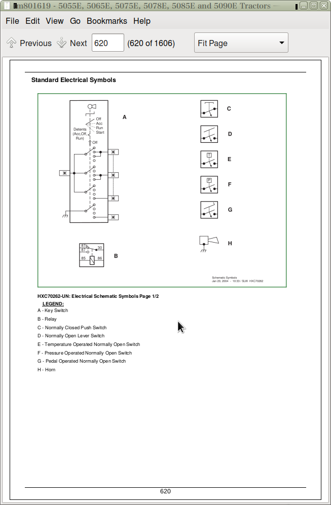
Standard Electrical Symbols
Diagnostic Diagram and Information on Symbols in DiagramHow to use an Electrical Diagram
Group 10: Operational and Preliminary Checks
Battery Test
Recharging Battery
Important Recommendations about Batteries
Testing the Alternator
Battery Check
Testing Starter Motor Solenoid
Starter Motor Test
Testing Starter Relay
Testing Ignition Switch.
Testing the Relay
Testing the Diode Block
Fuse Test
Testing the PTO Sensor
Testing the Light Switch
Testing Turning Lights Controller
Group 20: Theory of Operation
20A - Main Power Supply Circuit
20B - Engine Start-Up
20C - Engine Sensors
20D - Engine Air Filter Sensor
20E - Power Take-Off
20F - Fuel Level
20G - Horn
20H - Reverse Light and Backup Alarm
20I - Brake Lights
20J - Turn Signal and Hazard Warning Lights
20K - Work Lights
Group 30: Schematic
30A - Main Power Supply Circuit
30B - Engine Start-Up
30C - Engine Sensors
30D - Engine Air Filter Sensor
30E - Power Take-Off
30F - Fuel Level
30G - Horn
30H - Reverse Light and Backup Alarm
30I - Brake Lights
30J - Turn Signal and Hazard Warning Lights
30K - Work Lights
Group 50: Diagnostic Tests and Adjustments
50B - Engine Start-Up
50C - Engine Sensors
50D - Engine Air Filter Sensor
50E - Power Take-Off
50F - Fuel Level
50G - Horn
50H - Reverse Light and Backup Alarm
50I - Brake Lights
50J - Turn Signal and Hazard Warning Lights
50K - Work Lights
Section 240B: Electrical System - 5075E
Group 05: General Information
Summary of References
Electrical Designators
Visually Inspect Electrical System
Standard Electrical Symbols
Diagnostic Diagram and Information on Symbols in DiagramHow to use an Electrical Diagram
Group 10: Operational and Preliminary Checks
Battery Test
Recharging Battery
Important Recommendations about Batteries
Testing the Alternator
Battery Check
Testing Starter Motor Solenoid
Starter Motor Test
Testing Starter Relay
Testing Ignition Switch.
Testing the Relay
Testing the Diode Block
Fuse Test
Testing the PTO Sensor
Testing the Light Switch
Testing Turning Lights Controller
Group 15: Identification of Type
Identifying Electrical System Type
Group 20: Theory of Operation
20A - Main Power Supply Circuit - A-Type
20B - Main Power Supply Circuit - B-Type
20C - Main Power Supply Circuit - C-Type
20D - Starting the Engine - A- and B-Type
20E - Starting the Engine - C-Type
20F - Engine Sensors
20G - Engine Air Filter Sensor
20H - Power Take-Off
20I - Fuel Level
20J - Horn
20K - Reverse Light and Backup Alarm
20L - Brake Lights
20M - Turn Signal and Hazard Warning Lights - A-Type
20N - Turn Signal and Hazard Warning Lights - B- and C-Type
20O - Work Lights - A-Type
20P - Work Lights - B-Type
20Q - Work Lights - C-Type
Group 30: Schematic
30A - Main Power Supply Circuit - A-Type
30B - Main Power Supply Circuit - B-Type
30C - Main Power Supply Circuit - C-Type
30D - Starting the Engine - A- and B-Type
30E - Starting the Engine - C-Type
30F - Engine Sensors
30G - Engine Air Filter Sensor
30H - Power Take-Off
30I - Fuel Level
30J - Horn
30K - Reverse Light and Backup Alarm
30L - Brake Lights
30M - Turn Signal and Hazard Warning Lights - A-Type
30N - Turn Signal and Hazard Warning Lights - B- and C-Type
30O - Work Lights - A-Type
30P - Work Lights - B-Type
30Q - Work Lights - C-Type
Group 50: Diagnostic Tests and Adjustments
50D - Starting the Engine - A- and B-Type
50E - Starting the Engine - C-Type
50F - Engine Sensors
50G - Engine Air Filter Sensor
50H - Power Take-Off
50I - Fuel Level
50J - Horn
50K - Reverse Light and Backup Alarm
50L - Brake Lights
50M - Turn Signal and Hazard Warning Lights - A-Type
50N - Turn Signal and Hazard Warning Lights - B- and C-Type
50O - Work Lights - A-Type
50P - Work Lights - B-Type
50Q - Work Lights - C-Type
Section 240C: Electrical System - 5078E, 5085E and 5090E - Open Operator's Platform
Group 05: General Information
Summary of References
Electrical Designators
Visually Inspect Electrical System
Standard Electrical Symbols
Diagnostic Diagram and Information on Symbols in DiagramHow to use an Electrical Diagram
Group 10: Operational and Preliminary Checks
Battery Test
Recharging Battery
Important Recommendations about Batteries
Testing the Alternator
Battery Check
Testing Starter Motor Solenoid
Starter Motor Test
Testing Starter Relay
Testing Ignition Switch.
Testing the Relay
Testing the Diode Block
Fuse Test
Testing the PTO Sensor
Testing the Light Switch
Testing Turning Lights Controller
Group 20: Theory of Operation
20A - Main Power Supply Circuit
20B - Engine Start-Up
20C - Engine Sensors
20D - Engine Air Filter Sensor
20E - Power Take-Off
20F - Fuel Level
20G - Horn
20H - Reverse Light and Backup Alarm
20I - Brake Lights
20J - Turn Signal and Hazard Warning Lights
20K - Work Lights
Group 30: Schematic
30A - Main Power Supply Circuit
30B - Engine Start-Up
30C - Engine Sensors
30D - Engine Air Filter Sensor
30E - Power Take-Off
30F - Fuel Level
30G - Horn
30H - Reverse Light and Backup Alarm
30I - Brake Lights
30J - Turn Signal and Hazard Warning Lights
30K - Work Lights
Group 50: Diagnostic Tests and Adjustments
50B - Engine Start-Up
50C - Engine Sensors
50D - Engine Air Filter Sensor
50E - Power Take-Off
50F - Fuel Level
50G - Horn
50H - Reverse Light and Backup Alarm
50I - Brake Lights
50J - Turn Signal and Hazard Warning Lights
50K - Work Lights
Section 240D: Electrical System - 5078E, 5085E and 5090E - Cab
Group 05: General Information
Summary of References
Electrical Designators
Visually Inspect Electrical System
Standard Electrical Symbols
Diagnostic Diagram and Information on Symbols in DiagramHow to use an Electrical Diagram
Group 10: Operational and Preliminary Checks
Battery Test
Recharging Battery
Important Recommendations about Batteries
Testing the Alternator
Battery Check
Testing Starter Motor Solenoid
Starter Motor Test
Testing Starter Relay
Testing Key Switch
Testing the Relay
Testing the Diode Block
Fuse Test
Testing PTO Switch
Testing Lights Switch
Testing Turn Signal Switch
Group 20: Theory of Operation
20A - Main Power Supply Circuit
20B - Starting the Engine
20C - Sensores do Motor
20D - Engine Air Filter Sensor
20E - Power Take-Off
20F - Fuel Level
20G - Horn
20H - Backup Alarm
20I - Brake Lights
20J - Turn Signal and Hazard Warning Lights
20K - Work Lights
20L - Front Windshield Wiper and Washer
20M - Fan and Air Conditioning
20N - Electrical Power Outlets
20O - Console Light and Dome Light
20P - Rear Position Lights
Group 30: Schematic
30A - Main Power Supply Circuit
30B - Starting the Engine
30C - Engine Sensors
30D - Engine Air Filter Sensor
30E - Power Take-Off
30F - Fuel Level
30G - Horn
30H - Backup Alarm
30I - Brake Lights
30J - Turn Signal and Hazard Warning Lights
30K - Work Lights
30L - Front Windshield Wiper and Washer
30M - Fan and Air Conditioning
30N - Electrical Power Outlets
30O - Console Light and Dome Light
30P - Rear Position Lights
Group 50: Diagnostic Tests and Adjustments
50B - Starting the Engine
50C - Engine Sensors
50D - Engine Air Filter Sensor
50E - Power Take-Off
50F - Fuel Level
50G - Horn
50H - Backup Alarm
50I - Brake Lights
50J - Turn Signal and Hazard Warning Lights
50K - Work Lights
50L - Front Windshield Wiper and Washer
50M - Fan and Air Conditioning
50N - Electrical Power Outlets
50O - Console Light and Dome Light
50P - Rear Position Lights
Section 249A: Information on Electrical Components - 5055E and 5065E
Group 40A: Wiring Harnesses
Rear Wiring Harness (W01)
Engine Wiring Harness (W02)
Cowl Wiring Harness (W03)
Group 40B: Connectors
How to Use Connector Data
Wire Colors and Code Numbers
A01 - Fuse Box
A02 - Diode Module
A03 - Junction Box
B01 - Neutral Start Switch
B02 - Air Filter Restriction Sensor Connector
B03 - Engine Oil Pressure Sensor
B04 - Engine Speed Sensor Connector
B05 - Coolant Temperature Sensor
B06 - Fuel Level Sensor
E01 - Left-Hand Headlight Connector
E02 - Right-Hand Headlight Connector
E04 - Reverse Light Connector (If Equipped)
E09 - Rear Right-Hand Presence Light Connector
E10 - Rear Left-Hand Presence Light Connector
G02 - Alternator Connector
H03 - Horn Connector
H04 - Back-up Alarm Connector
KST - Starter Relay
K01 - Position Lights Relay
K03 - Rear Presence Lights Relay
K04 - Left-Hand Turn Signal Relay
K05 - Right-Hand Turn Signal Relay
K100 - Turn Signal Relay
M01 - Starter Motor Terminals
S01 - Starter Switch
S02 - PTO Switch
S03 - Horn Switch
S04 - Reverse Travel Switch
S05 - Hazard Warning Lights Switch
S06 - Brake Switch
S07 - Turn Signal Switch
S09 - Lights Switch
X05 - Ground Connector
X06 - Ground Connector
X10.1 - Instrument Panel Connector
X10.2 - Instrument Panel Connector
X11 - Connector between Front Wiring Harness and Rear Wiring Harness
X12 - Connector between Cowl Wiring Harness and Rear Wiring Harness
X13 - Brake Lights, Turn Signal Light and Rear Right-Hand Position Light
X14 - Brake Lights, Turn Signal Lights and Rear Left-Hand Position Light
X15 - Front Right-Hand Turn Signal and Position Light
X16 - Front Left-Hand Turn Signal and Position Light
X29 - Ground Wire of Front Wiring Harness
Section 249B: Information on Electrical Components - 5075E
Group 40A: Wiring Harnesses
Rear Wiring Harness (W01) - A-Type
Rear Wiring Harness (W01) - B-Type
Rear Wiring Harness (W01) - C-Type
Engine Wiring Harness (W02) - A- and B-Type
Engine Wiring Harness (W02) - C-Type
Cowl Wiring Harness (W03)
Group 40B: Connectors
How to Use Connector Data
Wire Colors and Code Numbers
A01 - Fuse Box - Type A
A01 - Fuse Box - Type B
A01 - Fuse Box - C-Type
A02 - Diode Module
A03 - Junction Box
A05 - Turn-Signal Switch
B01 - Neutral Start Switch
B02 - Air Filter Restriction Sensor Connector
B03 - Engine Oil Pressure Sensor
B04 - Engine Speed Sensor Connector
B05 - Coolant Temperature Sensor
B06 - Fuel Level Sensor
E01 - Left-Hand Headlight Connector
E02 - Right-Hand Headlight Connector
E04 - Reverse Light Connector (If Equipped)
E09 - Rear Right-Hand Presence Light Connector
E10 - Rear Left-Hand Presence Light Connector
G02 - Alternator Connector
H03 - Horn Connector
H04 - Back-up Alarm Connector
KST - Starter Relay
K01 - Position Lights Relay
K02 - Fuel Cut-Off Relay
K03 - Rear Presence Lights Relay
K04 - Left-Hand Turn Signal Relay - Type A
K04 - Left-Hand Turn Signal Relay - Type B
K04 - Left-Hand Turn Signal Relay - C-Type
K05 - Right-Hand Turn Signal Relay - Type A
K05 - Right-Hand Turn Signal Relay - Type B
K05 - Right-Hand Turn Signal Relay - C-Type
K06 - Fuel Transfer Pump Relay (if equipped)
K100 - Turn Signal Relay
M01 - Starter Motor Terminals
M04 - Fuel Transfer Pump
S01 - Starter Switch
S02 - PTO Switch
S03 - Horn Switch
S04 - Reverse Travel Switch
S05 - Hazard Warning Lights Switch - Type A
S05 - Hazard Warning Lights Switch - Type B
S05 - Hazard Warning Lights Switch - C-Type
S06 - Brake Switch
S07 - Turn Signal Switch
S09 - Lights Switch
X05 - Ground Connector
X06 - Ground Connector
X10.1 - Instrument Panel Connector
X10.2 - Instrument Panel Connector
X11 - Connector between Front Wiring Harness and Rear Wiring Harness - A- and B-Type
X11 - Connector between Front Wiring Harness and Rear Wiring Harness - C-Type
X12 - Connector between Cowl Wiring Harness and Rear Wiring Harness
X13 - Brake Lights, Turn Signal Light and Rear Right-Hand Position Light
X14 - Brake Lights, Turn Signal Lights and Rear Left-Hand Position Light
X15 - Front Right-Hand Turn Signal and Position Light
X16 - Front Left-Hand Turn Signal and Position Light
X29 - Ground Wire of Front Wiring Harness
Y01 - Fuel Cut-Off Solenoid
Section 249C: Information on Electrical Components - 5078E, 5085E and 5090E - Open Operator's Platform
Group 40A: Wiring Harnesses
Rear Wiring Harness (W01)
Engine Wiring Harness (W02)
Cowl Wiring Harness (W03)
Group 40B: Connectors
How to Use Connector Data
Wire Colors and Code Numbers
A01 - Fuse Box
A02 - Diode Module
A03 - Junction Box
B01 - Neutral Start Switch
B02 - Air Filter Restriction Sensor Connector
B03 - Engine Oil Pressure Sensor
B04 - Engine Speed Sensor Connector
B05 - Coolant Temperature Sensor
B06 - Fuel Level Sensor
E01 - Left-Hand Headlight Connector
E02 - Right-Hand Headlight Connector
E04 - Reverse Light Connector (If Equipped)
E09 - Rear Right-Hand Presence Light Connector
E10 - Rear Left-Hand Presence Light Connector
G02 - Alternator Connector
H03 - Horn Connector
H04 - Back-up Alarm Connector
KST - Starter Relay
K01 - Position Lights Relay
K02 - Fuel Cut-Off Relay
K03 - Rear Presence Lights Relay
K04 - Left-Hand Turn Signal Relay
K05 - Right-Hand Turn Signal Relay
K100 - Turn Signal Relay
M01 - Starter Motor Terminals
S01 - Starter Switch
S02 - PTO Switch
S03 - Horn Switch
S04 - Reverse Travel Switch
S05 - Hazard Warning Lights Switch
S06 - Brake Switch
S07 - Turn Signal Switch
S09 - Lights Switch
X05 - Ground Connector
X06 - Ground Connector
X10.1 - Instrument Panel Connector
X10.2 - Instrument Panel Connector
X11 - Connector between Front Wiring Harness and Rear Wiring Harness
X12 - Connector between Cowl Wiring Harness and Rear Wiring Harness
X13 - Brake Lights, Turn Signal Light and Rear Right-Hand Position Light
X14 - Brake Lights, Turn Signal Lights and Rear Left-Hand Position Light
X15 - Front Right-Hand Turn Signal and Position Light
X16 - Front Left-Hand Turn Signal and Position Light
X29 - Ground Wire of Front Wiring Harness
Y01 - Fuel Cut-Off Solenoid
Section 249D: Electrical Components Information - 5078E, 5085E and 5090E - Cab Tractors
Group 40A: Wiring Harnesses
Cab Main Wiring Harness (W01)
Engine Wiring Harness (W02)
Cowl Wiring Harness (W03)
Front Console Wiring Harness (W04)
Cab Roof Wiring Harness (W05)
Group 40B: Connectors
How to Use Connector Data
Wire Colors and Code Numbers
A01 - Fuse and Relay Box
A02 - Diode Module
A03 - Junction Box
A07 - Dome Light and Switch Assembly
B01 - Neutral Start Switch
B02 - Air Filter Restriction Sensor
B03 - Engine Oil Pressure Sensor
B04 - Engine Speed Sensor
B05 - Coolant Temperature Sensor
B06 - Fuel Level Sensor
B07 - Air Conditioning Deicing Switch
B08 - Air Conditioning High/Low Pressure Switch
E01 - Left-Hand Headlight
E02 - Right-Hand Headlight
E07 - Front Right-Hand Work Light
E08 - Front Left-Hand Work Light
E09 - Rear Right-Hand Work Light
E10 - Rear Left-Hand Work Light
E19 - Console Light
G02 - Alternator Connector
H03 - Horn Connector
H04 - Backup Alarm
KST - Starter Relay
K02 - Left-Hand Turn Signal Relay
K03 - Right-Hand Turn Signal Relay
K04 - PTO in Neutral Relay
K05 - Turn Signal Relay
K06 - Trailer Connector Relay
K08 - Rear Work Lights Relay
K09 - Front Work Lights Relay
K10 - Tail Lights, Turn Signal Lights and Brake Lights Relay
K11 - Fuel Cut-Off Relay
K12 - Neutral Start Relay
K13 - Fuel Transfer Pump Relay
K20 - Air Conditioning Relay
K21 - Wiper Relay
K22 - Left-Hand Fan Relay
K23 - Right-Hand Fan Relay
K26 - Accessories Relay
M01 - Starter Motor
M02 - Left-Hand Fan Motor
M03 - Right-Hand Fan Motor
M04 - Fuel Transfer Pump
M05 - Front Wiper Motor
M06 - Front Washer Pump
M11 - Air Conditioning Compressor
R03 - Resistor
S01 - Starter Switch
S02 - PTO Switch
S03 - Horn Switch
S04 - Reverse Travel Switch
S05 - Hazard Warning Lights Switch
S06 - Brake Switch
S07 - Turn Signal Switch
S08 - Fan Switch
S09 - Lights Switch
S10 - AC On/Off Switch
S13 - Left-Hand Door Switch
S30 - Front Wiper Switch
X03 - Accessory Socket
X10.1 - Instrument Panel Connector
X10.2 - Instrument Panel Connector
X11 - Connector (W02 and W04)
X12 - Connector (W03 and W04)
X13 - Brake Lights, Turn Signal Light and Rear Right-Hand Position Light
X14 - Brake Lights, Turn Signal Lights and Rear Left-Hand Position Light
X15 - Front Right-Hand Turn Signal
X16 - Front Left-Hand Turn Signal
X21 - Connector (W01 and W05)
X22.1 - Connector (W01 and W04)
X22.2 - Connector (W01 and W04)
X29 - Engine Wiring Harness Ground Connection
X 30 - Main Cab Wiring Harness Ground Wire
X31 - Junction Block
X32 - Power Outlet
X33 - Front Console Wiring Harness Ground Connection
X34 - Cab Roof Wiring Harness Ground Wire
X35 - Antenna Ground Wire
X36 - Evaporator Ground
Y01 - Fuel Shut-Off Solenoid
Section 250: Drive Train
Group 05: General Information
Summary of References
Group 20: Theory of Operation
Clutch Operation—Dual Clutch
Transmission Lubrication System
CollarShift Transmission—Gear Shift Power Flow
CollarShift Transmission—Range Shift Power Flow
SyncShuttle™ Transmission—Gear Shift Power Flow
SyncShuttle™ Transmission Synchronizer Operation—Reverse and 2nd Gear (Disk-and-Plate Type Synchronizer)
SyncShuttle™ Transmission Synchronizer Operation—1st and 3rd Gear (Cone-Type Synchronizer)
CollarShift Transmission—Shift Range Power Flow
PTO Power Flow
Rear PTO Operation
Mechanical Front Wheel Drive (MFWD) Operation
Differential Power Flow
Differential Lock Operation
Final Drive Operation
Group 50: Tests for Diagnostics and Adjustments
Diagnostic Information
Isolate the Problem Area
Traction Clutch Slips
Traction Clutch Dragging
Traction Clutch Does Not Engage
Traction Clutch Grabs
Traction Clutch Squeaks
Traction Clutch Does Not Release
Traction Clutch Chatters
Traction Clutch Rattles
Traction Clutch Engagement Is Noisy
Excessive Vibration in Traction Clutch
Clutch Pedal Does Not Return
Clutch Pedal Loose
Clutch Pedal Pulsates
Jerky or Rough Transmission of Power
Low Transmission Oil Level (Excessive Oil Leakage)
Gears Beating, Hard Gearshifting or Not Shifting
Two Speeds Engage Together
Transmission Will Not Stay in Gear
Transmission Noisy
PTO Noisy
PTO Hard to Engage
PTO Will Not Operate
PTO Will Not Stay Engaged
Excessive Differential Noise
Differential Does Not Work
No Differential Lock
Differential Chatters
Axle Noise
Axle Shaft Will Not Turn
Adjusting PTO Clutch Lever Linkage
Section 259: Drive Train Components Information
Group 05: General Information
Information on Component Location
Group 40: Drive Train Components
Drive Train Components
Clutch Components—Dual
CollarShift Transmission Components
Transmission Components—TSS
Final Drive Components
Rear PTO Components
Section 260: Steering and Brakes
Group 05: General Information
Summary of References
Group 20: Theory of Operation
Steering System Operation
Steering Valve Operation — Manual Turn and Neutral
Steering Valve Operation — Power Assisted Turning
Brake System Operation
Brake Valve Operation
Brake Valve Operation — Continued
Brake Valve Operation — Resting Brake Pedal
Group 50: Tests for Diagnostics and Adjustments
Isolate the Problem — Steering System
Slow Steering or Loss of Steering
Isolate the Problem — Brakes
Excessive Brake Pedal Leak
Excessive Brake Vibration
Steering Pump Rate of Flow Test
Steering Valve Relief Valve Test
Steering Cylinder Leakage Test
Steering Valve Leak Lest
Checking the Toe-In — Two-Wheel Drive
Adjusting the Toe-In — Two-Wheel Drive
Checking the Toe-In — Four-Wheel Drive
Adjusting the Toe-In — Four-Wheel Drive
Adjusting the Turning Angle of the Steering Backstop — Four-Wheel Drive
Brake Pedal Adjustment
Bleed Brake System
Section 269: Steering and Brake Components Information
Group 40A: Steering System Components
Steering System Components
Group 40B: Brake Components
Brake System Components
Section 270: Hydraulic System
Group 05: General Information
Summary of References
Standard Hydraulic Symbols
Hydraulic Designators
Hydraulic System Testing Precautions
Aeration and Cavitation
Hydraulic Components
Oil Storage and Filling
Oil Filtration
Group 10: Operational and Preliminary Checks
Visually Inspect Hydraulic System
Hydraulic Troubleshooting Tips
Preliminary Hydraulic System Inspection
Group 15: Identification of Type
Identification of Hydraulic System Type
Group 20A: Theory of Operation - A-Type
Hydraulic System
Hydraulic Filter and Mesh Filter
Hydraulic Pump
Mita Pick-Up Hitch Valve—Neutral Position
Mita Pick-Up Hitch Valve—Raise Position
Mita Pick-Up Hitch Valve—Lower Position
Mita Pick-Up Hitch Valve—Rate-of-Drop Modulation
Mita Pick-Up Hitch Valve—Overpressure Relief Valve
Pick-Up Hitch Position Control
Pick-Up Hitch Sensitivity Control
Mita Selective Control Valve—Neutral Position
Mita Selective Control Valve—Retract Position
Mita Selective Control Valve—Extend Position
Mita Selective Control Valve—Float Position
Quick-Couplers
Group 20B: Theory of Operation - B-Type
Hydraulic System
Hydraulic Filter and Mesh Filter
Hydraulic Pump
Eaton Pick-Up Hitch Valve—Neutral Position
Eaton Pick-Up Hitch Valve—Raise Position
Eaton Pick-Up Hitch Valve—Lower Position
Eaton Pick-Up Hitch Valve—Rate-of-Drop Modulation
Pick-Up Hitch Valve—Overpressure Relief Valve
Pick-Up Hitch Sensitivity Control
Eaton Selective Control Valve—Neutral Position
Eaton Selective Control Valve—Retract Position
Eaton Selective Control Valve—Extend Position
Eaton Selective Control Valve—Float Position
Quick-Couplers
Group 20C: Theory of Operation - Type C
Hydraulic System
Hydraulic Filter and Mesh Filter
Hydraulic Pump
Valmova-Sauer Danfoss Pick-Up Hitch Valve—Neutral Position
Valmova-Sauer Danfoss Pick-Up Hitch Valve—Raise Position
Valmova-Sauer Danfoss Pick-Up Hitch Valve—Lower Position
Valmova-Sauer Danfoss Pick-Up Hitch Valve—Rate-of-Drop Modulation
Pick-Up Hitch Valve—Overpressure Relief Valve
Pick-Up Hitch Sensitivity Control
Valmova-Sauer Danfoss Selective Control Valve—Neutral Position
Valmova-Sauer Danfoss Selective Control Valve—Extend and Retract Position
Valmova-Sauer Danfoss Selective Control Valve—Float Position
Quick-Couplers
Group 20D: Theory of Operation - Type D
Hydraulic System
Hydraulic Filter and Mesh Filter
Hydraulic Pump
Hema Pick-Up Hitch Valve
Hema Pick-Up Hitch Valve—Main Relief Valve
Hema Pick-Up Hitch Valve—Rate-of-Drop Modulation
Pick-Up Hitch Valve—Overpressure Relief Valve
Pick-Up Hitch Sensitivity Control
Valmova-Sauer Danfoss Double Selective Control Valve—Neutral Position
Valmova-Sauer Danfoss Double Selective Control Valve—Extend and Retract Position
Valmova-Sauer Danfoss Double Selective Control Valve—Float Position
Quick-Couplers
Group 30: Hydraulic Schematics
Main Hydraulic Schematic—A-Type
Main Hydraulic Schematic—B-Type
Main Hydraulic Schematic—C-Type
Main Hydraulic Schematic—D-Type
Group 50A: Diagnostic Tests and Adjustments—A-Type
Diagnostic Information
Norms of Safety
Hydraulic Oil Heating Procedures
Pick-Up Hitch Raise Cycle Test
Pick-Up Hitch Leak Test
Selective Control Valve Leak Test
Hydraulic Pump Flow Test—Without Selective Control Valve
Hydraulic Pump Flow Test—With Selective Control Valve
Main Relief Valve Test
Adjusting Main Relief Valve
Adjusting Pick-Up Hitch Position Control Lever
Adjusting Pick-Up Hitch Sensitivity Control Lever
Adjusting Pick-Up Hitch Control Lever Friction
Adjusting Return Spring Assembly
Controlling Pressure Rod Measurement
Hydraulic Pump without Oil Flow
Insufficient Hydraulic Pump Delivery
Very Slow Hydraulic Functions
Excessive Hydraulic Pump Pressure
Slow Response from the Hydraulic Pump
Excessive Hydraulic Pump Noise During Operation
Pick-Up Hitch Does Not Rise or Rises Slowly
Hydraulic Hitch Does Not Lower or Lowers Slowly
Pick-Up Hitch Lowers after Engine Is Turned Off
Remote Cylinder will not Extend or Retract
Remote Cylinder Lowers under Load
Remote Cylinder Operates Very Fast or Too Slowly
Group 50B: Diagnostic Tests and Adjustments—B-Type
Diagnostic Information
Norms of Safety
Hydraulic Oil Heating Procedures
Pick-Up Hitch Raise Cycle Test
Pick-Up Hitch Leak Test
Selective Control Valve Leak Test
Hydraulic Pump Flow Test—With Selective Control Valve
Main Relief Valve Test
Adjusting Main Relief Valve
Adjusting Pick-Up Hitch Control Lever Friction
Adjusting Pick-Up Hitch Position Sensor Link
Adjusting Pick-Up Hitch Depth Sensor Link
Hydraulic Pump without Oil Flow
Insufficient Hydraulic Pump Delivery
Very Slow Hydraulic Functions
Excessive Hydraulic Pump Pressure
Slow Response from the Hydraulic Pump
Excessive Hydraulic Pump Noise During Operation
Pick-Up Hitch Does Not Rise or Rises Slowly
Hydraulic Hitch Does Not Lower or Lowers Slowly
Pick-Up Hitch Lowers after Engine Is Turned Off
Remote Cylinder will not Extend or Retract
Remote Cylinder Lowers under Load
Remote Cylinder Operates Very Fast or Too Slowly
Group 50C: Diagnostic Tests and Adjustments—C-Type
Diagnostic Information
Norms of Safety
Hydraulic Oil Heating Procedures
Pick-Up Hitch Raise Cycle Test
Pick-Up Hitch Leak Test
Selective Control Valve Leak Test
Hydraulic Pump Flow Test—Without Selective Control Valve
Hydraulic Pump Flow Test—With Selective Control Valve
Main Relief Valve Test
Adjusting Main Relief Valve
Adjusting Pick-Up Hitch Control Lever Friction
Adjusting Pick-Up Hitch Position Sensor Link
Adjusting Pick-Up Hitch Depth Sensor Link
Hydraulic Pump without Oil Flow
Insufficient Hydraulic Pump Delivery
Very Slow Hydraulic Functions
Excessive Hydraulic Pump Pressure
Slow Response from the Hydraulic Pump
Excessive Hydraulic Pump Noise During Operation
Pick-Up Hitch Does Not Rise or Rises Slowly
Hydraulic Hitch Does Not Lower or Lowers Slowly
Pick-Up Hitch Lowers after Engine Is Turned Off
Remote Cylinder will not Extend or Retract
Remote Cylinder Lowers under Load
Remote Cylinder Operates Very Fast or Too Slowly
Group 50D: Diagnostic Tests and Adjustments—D-Type
Diagnostic Information
Norms of Safety
Hydraulic Oil Heating Procedures
Pick-Up Hitch Raise Cycle Test
Pick-Up Hitch Leak Test
Selective Control Valve Leak Test
Hydraulic Pump Flow Test—Without Selective Control Valve
Hydraulic Pump Flow Test—With Selective Control Valve
Main Relief Valve Test
Adjusting Main Relief Valve
Pick-Up Hitch Cylinder Supply Pressure Test
Adjusting Load Sense Relief Valve
Adjusting Pick-Up Hitch Sensitivity Control and Position Control Cable
Adjusting Pick-Up Hitch Control Lever Friction
Adjusting Pick-Up Hitch Position Sensor Link
Adjusting Pick-Up Hitch Depth Sensor Link
Hydraulic Pump without Oil Flow
Insufficient Hydraulic Pump Delivery
Very Slow Hydraulic Functions
Excessive Hydraulic Pump Pressure
Slow Response from the Hydraulic Pump
Excessive Hydraulic Pump Noise During Operation
Pick-Up Hitch Does Not Rise or Rises Slowly
Hydraulic Hitch Does Not Lower or Lowers Slowly
Pick-Up Hitch Lowers after Engine Is Turned Off
Remote Cylinder will not Extend or Retract
Remote Cylinder Lowers under Load
Remote Cylinder Operates Very Fast or Too Slowly
Section 279: Information on Hydraulic Components
Group 40: Hydraulic Components
Hydraulic Pump
Steering Cylinder
Hydraulic Filter
Mesh Filter
Steering Valve
Brake Valve
Pick-Up Hitch Valve and Selective Control Valves
Selective Control Valves Couplers
Oil Cooler
Section 290: Cab
Group 05: General Information
Summary of References
Group 10: Operational and Preliminary Checks
Heating, Ventilation and Air Conditioning Preliminary Checks
Heating, Ventilation and Air Conditioning Operational Checks
Group 20: Theory of Operations
Principle of Heat Exchange
Air Conditioning System Operation
Air Conditioning Compressor Operation
Air Conditioning Condenser Operation
Air Conditioning High/Low Pressure Switch Operation
Air Conditioning Evaporator Operation
Air Conditioning Thermostat Operation
Air Conditioning Expansion Valve Operation
Air Conditioning Receiver-Dryer Operation
Air Conditioning On-Off and Temperature Control Knob Operation
Heater Control Dial Operation
Heating and Ventilation Operation
Group 30: Schematic
Air Conditioning System
Heating and Ventilation System
Group 50: Diagnostic Tests and Adjustments
Safety in the Workplace
Handling Refrigerant
Safety Equipment
In the Event of an Emergency
Storage of Refrigerant Containers
Refrigerant R134a
Important
Special Tools
Installing Air Conditioning Test Equipment
Air Conditioning System Pressure Test
Air Conditioning System Static Pressure Test
Temperature Drop Test
Section 299: Information on Cab Components
Group 40: Cab Components
Air Conditioning Compressor
A/C Condenser
Air Conditioning High-Low Pressure Switch
Air Conditioning Thermostat
Air Conditioning Evaporator
Air Conditioning Expansion Valve
Air Conditioning Receiver-Dryer
Air Conditioning On/Off Switch
Air Conditioning Temperature Control Knob
Heater Control Knob
Cab Fan Speed Control Selector
John Deere Tractors 5055E, 5065E, 5075E, 5078E, 5085E, 5090E Diagnosis and Tests Service Technical Manual (TM801619)
![]()