
John Deere Tractors 5105ML, 5095MH, 5095M, 5085M, 5075M, 5065M Diagnosis and Tests Service Technical Manual (TM102519)

Complete Diagnosis & Tests Technical Manual with electrical wiring diagrams for John Deere Tractors 5065M, 5075M (IT4/Stage IIIB), 5085M, 5095M, 5105M, 5105ML & 5095MH (Tier 3/Stage IIIA) Series, with workshop information to maintain, diagnose, and service like professional mechanics.
John Deere Tractors 5065M, 5075M, 5085M, 5095M, 5105M, 5105ML, 5095MH workshop Diagnosis & Tests technical manual includes:
* Numbered table of contents easy to use so that you can find the information you need fast.
* Detailed sub-steps expand on repair procedure information
* Numbered instructions guide you through every repair procedure step by step.
* Troubleshooting and electrical service procedures are combined with detailed wiring diagrams for ease of use.
* Notes, cautions and warnings throughout each chapter pinpoint critical information.
* Bold figure number help you quickly match illustrations with instructions.
* Detailed illustrations, drawings and photos guide you through every procedure.
* Enlarged inset helps you identify and examine parts in detail.
tm102519 - 5065M and 5075M (IT4_Stage IIIB), 5085M, 5095M, 5095MH, 5105M and 5105ML (Tier 3_Stage IIIA) Tractors Diagnostic Technical Manual.pdf
tm102519 - 5065M and 5075M (IT4_Stage IIIB), 5085M, 5095M, 5095MH, 5105M and 5105ML (Tier 3_Stage IIIA) Tractors Diagnostic Technical Manual.epub
Total Pages: 3,202 pages
File Format: PDF/EPUB/MOBI/AZW (PC/Mac/Android/Kindle/iPhone/iPad; bookmarked, ToC, Searchable, Printable)
Language: English
MAIN SECTIONS
Foreword
General
Safety
General References
Diagnostic Trouble Codes
CCU Code Diagnostics
ECU Code Diagnostics
HCU Code Diagnostics
ICC Code Diagnostics
PTR Code Diagnostics
Observable Symptoms
Engine Symptoms
Fuel and Air Symptoms
Electrical Symptoms
Control Unit Symptoms
SyncShuttle Plus Transmission Symptoms
SyncReverser Transmission Symptoms
PowrReverser/PowrReverser Plus Transmission Symptoms
Drive Systems Symptoms
Steering and Brake Symptoms
Hydraulic Symptoms
Operator Station Symptoms
System Diagnosis
Engine System Diagnosis
Fuel and Air System Diagnosis
Electrical System Diagnosis
Control Unit System Diagnosis
SyncShuttle Plus Transmission System Diagnosis
SyncReverser Transmission System Diagnosis
PowrReverser/PowrReverser Plus Transmission System Diagnosis
Drive Systems Diagnosis
Steering and Brake System Diagnosis
Hydraulic System Diagnosis
Operator Station System Diagnosis
Engines
General Information
Test Procedures and Adjustments
Cooling System
Engine Theory of Operation
Fuel and Air
General Information
Fuel and Air Theory of Operation
Electrical System
General Electrical References
Connector Information
Harness Information
SE01, SE02 - Power, Starting, PTM Fuel Injection
SE03 - Accessory Power and SE04 - Horn
SE05 - Light Switch, Headlights, and Signal Lights
SE05A - Cab Work Lighting
SE05B - Open Operator Station Work Lighting
SE06 - Turn Signal Switch and Warning Lights
SE07 - Light Switch, Headlights, Signal, License & Clearance Lights
SE07A - Cab Work Lighting (with Work Light Switches)
SE07B - Open Operator Station Work Lighting
SE08 - Warning Light Switch and Turn Signal Lighting
SE09, SE10, SE12 Junction Block Power, Trailer Connector, Loader Lights
SE11 - Trailer Connector (with Implement Flood Light Connector)
SE13, SE14, SE15 - Backup Alarm, Mid-Mount SCV, Power Outlets
SE16 - Heating, SE17 - Air Conditioner, SE19 - Wipers
SE20, SE21 - Wipers (Single Speed)
SE22 - Dome Light, Radio, and SE23 - Air Seat
SE24A, SE24B - Standard\Deluxe Instrument Cluster Control (ICC) Unit
SE25 - Diff Lock, Seat, Rear PTO, Wheel Speed, Ground Drive PTO
SE27, SE28 - Mechanical Front-Wheel Drive (MFWD), Brake Switch
SE26 - EH System Relay, and SE29 - EH Control (EHC) Unit
SE29A - Power Train Reverser (PTR) Control Unit Functions
SE29B - Chassis Control Unit (CCU) Functions
SE29C - Hitch Control Unit (HCU) Functions
SE30, SE31 - 4045 and 5030 Engine Control Unit (ECU)
SE32 - Controller Area Network Terminators/Service ADVISOR Connector
Control Units
General References
CCU - Chassis Control Unit
ECU - Engine Control Unit
HCU - Hitch Control Unit
ICC - Instrument Cluster Control
PTR - Power Train Reverser
Transmission
Preliminary and Operational Checks
Tests and Adjustments
Theory of Operation
Drive Systems
Preliminary and Operational Checks
Tests and Adjustments
Theory of Operation
Steering and Brakes
Preliminary and Operational Checks
Test and Adjustments
Theory of Operation
Hydraulics
Preliminary and Operational Checks
Tests and Adjustments
Theory of Operation
Theory of Operation-Mono Block SCV Valves
SCV Theory of Operation-Sectional Valves
Operator Station
Preliminary and Operational Checks
Tests and Adjustments
Theory of Operation
Service Tools and Installing Test Equipment
Dealer Fabricated Tools
Service Tools and Kits
Transmission - Install Test Equipment
Drive Systems - Install Test Equipment
Steering and Brakes - Install Test Equipment
Hydraulics - Install Test Equipment
Operator Station - Install Test Equipment
tm102519 - 5065M and 5075M (IT4/Stage IIIB), 5085M, 5095M, 5095MH, 5105M and 5105ML (Tier 3/Stage IIIA) Tractors Diagnostic Technical Manual
Table of Contents
Foreword
Section 210: General
Group 05: Safety
Recognize Safety Information
Understand Signal Words
Handle Fuel Safely—Avoid Fires
Park Machine Safely
Support Machine Properly
Wear Protective Clothing
Replace Safety Signs
Use Proper Lifting Equipment
Remove Paint Before Welding or Heating
Practice Safe Maintenance
Use Proper Tools
Decommissioning — Proper Recycling and Disposal of Fluids and Components
Handle Starting Fluid Safely
Work In Ventilated Area
Work in Clean Area
Avoid Harmful Asbestos Dust
Avoid High-Pressure Fluids
Service Cooling System Safely
Stay Clear of Rotating Drivelines
Protect Against High Pressure Spray
Clean Vehicle of Hazardous Pesticides
Illuminate Work Area Safely
Live With Safety
Service Machines Safely
Prevent Acid Burns
Follow Safety Instructions
Service Tires Safely
Keep ROPS Installed Properly
Construct Dealer-Made Tools Safely
Prevent Battery Explosions
Avoid Heating Near Pressurized Fluid Lines
Group 15: General References
Regions and Country Versions
Features and Accessories
Metric Bolt and Screw Torque Values
Unified Inch Bolt and Screw Torque Values
Glossary of Terms
JIC Hydraulic Symbols
Wiring Diagram and Schematic Information
Electrical Schematic Symbols
Reading Wiring Schematics and Diagrams
Visually Inspect Electrical System
Electrical Procedure
Using a Probe Light
Circuit Types
Circuit Malfunctions
Relay Circuit Types
Using a Digital Multimeter
Troubleshooting Unresolved Electrical/Electronic Problems
Section 211: Diagnostic Trouble Codes
Group CCU: CCU Code Diagnostics
CCU 000100.01 - Engine Oil Pressure Signal Extremely Low
CCU 000100.04 - Engine Oil Pressure Input Voltage Low
CCU 000110.00 - Engine Coolant Temperature Signal Extremely High
CCU 000110.03 - Engine Coolant Temperature Sensor Out of Range High
CCU 000110.04 - Engine Coolant Temperature Sensor Out of Range Low
CCU 000110.16 - Engine Coolant Temperature Signal Moderately High
CCU 000237.02 - VIN Security Data Conflict
CCU 000237.14 - VIN Security Not Enabled
CCU 000237.31 - VIN Security Messages Missing
CCU 000569.05 - Rear Differential Lock Solenoid Circuit Fault
CCU 000628.02 - CCU EOL Data Fault
CCU 000629.12 - CCU Control Unit Fault
CCU 000630.14 - Rear PTO Configuration Invalid
CCU 000676.03 - Engine Air Heater Relay Output Signal Received
CCU 000676.05 - Engine Air Heater Relay Output Signal Not Received
CCU 001638.00 - Hydraulic Oil Temperature Very Hot
CCU 001638.03 - Hydraulic Oil Temperature Sensor Circuit Voltage High
CCU 001638.04 - Hydraulic Oil Temperature Sensor Circuit Voltage Low
CCU 001638.16 - Hydraulic Oil Temperature High
CCU 001883.00 - Rear PTO Overspeed
CCU 001883.01 - Rear PTO Underspeed
CCU 002818.31 - Operator Presence Switch Not Activated
CCU 003509.03 - Sensor Supply Voltage Out of Range High
CCU 003509.04 - Sensor Supply Voltage Out of Range Low
CCU 523839.02 - Secondary Brake Switch Conflict
CCU 524016.04 - CCU Switched Supply Voltage Low
CCU 524037.02 - MFWD Switch Circuit Fault
CCU 524223.03 - Differential Lock Circuit Voltage High
CCU 524224.14 - PTO Switch Voltage Mismatch
CCU 524235.05 - MFWD Solenoid Circuit Fault
CCU 524252.05 - Rear PTO Solenoid Circuit Fault
CCU 524255.31 - Rear Remote PTO Enabled
Group ECU: ECU Code Diagnostics
ECU 000029.03 - Throttle #2 (Hand) Signal Out Of Range High
ECU 000029.04 - Throttle #2 (Hand) Signal Out Of Range Low
ECU 000091.03 - Throttle #1 (Foot) Signal Out Of Range High
ECU 000091.04 - Throttle #1 (Foot) Signal Out Of Range Low
ECU 000094.03 - Low Pressure Fuel Signal Out of Range High
ECU 000094.04 - Low Pressure Fuel Signal Out of Range Low
ECU 000094.17 - High Pressure Fuel System - Pressure Signal Slightly Low
ECU 000094.18 - High Pressure Fuel System - Pressure Signal Slightly Low
ECU 000097.03 - Water In Fuel (WIF) Signal Out Of Range High (4.5L)
ECU 000097.04 - Water In Fuel (WIF) Signal Out Of Range Low (4.5L)
ECU 000097.16 - Water In Fuel Detected
ECU 000100.01 - Engine Oil Pressure Signal Extremely Low
ECU 000100.04 - Engine Oil Pressure Signal Out Of Range Low
ECU 000105.00 - Intake Manifold Air Temperature Signal Extremely High
ECU 000105.03 - Intake Manifold Air Temperature Signal Out Of Range High
ECU 000105.04 - Intake Manifold Air Temperature Signal Out Of Range Low
ECU 000105.15 - Intake Manifold Air Temperature Signal Slightly High
ECU 000105.16 - Intake Manifold Air Temperature Signal Moderately High
ECU 000108.02 - Barometric Pressure Signal Invalid
ECU 000110.00 - Engine Coolant Temperature Signal Extremely High
ECU 000110.03 - Engine Coolant Temperature Signal Out Of Range High
ECU 000110.04 - Engine Coolant Temperature Signal Out Of Range Low
ECU 000110.15 - Engine Coolant Temperature Signal Slightly High
ECU 000110.16 - Engine Coolant Temperature Signal Moderately High
ECU 000157.03 - Fuel Rail Pressure Signal Out Of Range High (4.5L)
ECU 000157.04 - Fuel Rail Pressure Signal Out Of Range Low (4.5L)
ECU 000157.10 - Fuel Rail Pressure Rate Of Change Abnormal (4.5L)
ECU 000157.17 - Fuel Rail Pressure Not Developed (4.5L)
ECU 000158.17 - ECU Power Down Error
ECU 000174.00 - Fuel Temperature Signal Extremely High (4.5L)
ECU 000174.03 - Fuel Temperature Signal Out Of Range High (4.5L)
ECU 000174.04 - Fuel Temperature Signal Out Of Range Low (4.5L)
ECU 000174.16 - Fuel Temperature Signal Moderately High (4.5L)
ECU 000237.02 - VIN Security Data Invalid
ECU 000237.13 - VIN Option Code Security Data Conflict
ECU 000237.31 - VIN Security Data Missing
ECU 000611.03 - Injector Shorted To Power
ECU 000611.04 - Injector Shorted To Ground
ECU 000627.01 - All Electronic Injector Circuit Have High Resistance
ECU 000629.12 - ECU Boot Block Error
ECU 000629.13 - ECU Boot Block Error
ECU 000636.02 - Camshaft Sensor Signal Invalid
ECU 000636.05 - Camshaft Sensor Circuit Has High Resistance
ECU 000636.06 - Camshaft Sensor Circuit Has Low Resistance
ECU 000636.08 - Camshaft Sensor Signal Missing
ECU 000636.10 - Camshaft Signal Rate Of Change Abnormal
ECU 000637.02 - Crankshaft Position Sensor Signal Invalid
ECU 000637.05 - Engine Position Sensor Circuit Has High Resistance
ECU 000637.06 - Engine Position Sensor Circuit Has Low Resistance
ECU 000637.07 - Crankshaft Position And Position Signals Out Of Sync
ECU 000637.08 - Crankshaft Position Timing Sensor Signal Missing
ECU 000637.10 - Crankshaft Position Signal Rate Of Change Abnormal
ECU 000651.00 - Injector #1 Data Extremely High (4.5L)
ECU 000651.01 - Injector #1 Data Extremely Low (4.5L)
ECU 000651.02 - Injector #1 Part Number Data Invalid (4.5L)
ECU 000651.05 - Injector #1 Circuit Has High Resistance
ECU 000651.06 - Injector #1 Circuit Has Low Resistance
ECU 000651.07 - Injector #1 Not Responding (4.5L)
ECU 000651.13 - Injector #1 Calibration Fault
ECU 000652.00 - Injector #2 Data Extremely High (4.5L)
ECU 000652.01 - Injector #2 Data Extremely Low (4.5L)
ECU 000652.02 - Injector #2 Part Number Data Invalid (4.5L)
ECU 000652.05 - Injector #2 Circuit Has High Resistance
ECU 000652.06 - Injector #2 Circuit Has Low Resistance
ECU 000652.07 - Injector #2 Not Responding (4.5L)
ECU 000652.13 - Injector #2 Calibration Fault
ECU 000653.00 - Injector #3 Data Extremely High (4.5L)
ECU 000653.01 - Injector #3 Data Extremely Low (4.5L)
ECU 000653.02 - Injector #3 Part Number Invalid (4.5L)
ECU 000653.05 - Injector #3 Circuit Has High Resistance
ECU 000653.06 - Injector #3 Circuit Has Low Resistance
ECU 000653.07 - Injector #3 Not Responding (4.5L)
ECU 000653.13 - Injector #3 Calibration Fault
ECU 000654.00 - Injector #4 Data Extremely High (4.5L)
ECU 000654.01 - Injector #4 Data Extremely Low (4.5L)
ECU 000654.02 - Injector #4 Part Number Invalid (4.5L)
ECU 000654.05 - Injector #4 Circuit Has High Resistance
ECU 000654.06 - Injector #4 Circuit Has Low Resistance
ECU 000654.07 - Injector #4 Not Responding (4.5L)
ECU 000654.13 - Injector #4 Calibration Fault
ECU 000655.05 - Injector #5 Circuit Has High Resistance (3.0L)
ECU 000655.06 - Injector #5 Circuit Has Low Resistance (3.0L)
ECU 000655.13 - Injector #5 Calibration Fault (3.0L)
ECU 000676.03 - Cold Start Aid Relay Output Signal Received When Not Expected
ECU 000676.05 - Cold Start Aid Relay Output Signal Not Received
ECU 001136.00 - ECU Temperature Signal Extremely High
ECU 001136.16 - ECU Temperature Signal Moderately High
ECU 001347.03 - High Pressure Fuel Pump Control Valve Signal Out Of Range High (4.5L)
ECU 001347.05 - High Pressure Fuel Pump Solenoid Circuit Has High Resistance (4.5L)
ECU 001347.07 - High Pressure Fuel Pump Not Able To Meet Required Rail Pressure (4.5L)
ECU 001569.31 - Engine Power Derate Condition Exists
ECU 002003.09 - PTR Control Unit Message Missing
ECU 003509.03 - Sensor Supply #1 Voltage Out Of Range High
ECU 003509.04 - Sensor Supply #1 Voltage Out Of Range Low
ECU 003510.03 - Sensor Supply #2 Voltage Out Of Range High
ECU 003510.04 - Sensor Supply #2 Voltage Out Of Range Low
ECU 003511.03 - Sensor Supply #3 Voltage Out Of Range High
ECU 003511.04 - Sensor Supply #3 Voltage Out Of Range Low
ECU 003597.01 - All Electronic Unit Pump Circuits Have High Resistance
ECU 003597.18 - Battery Voltage Moderately Low
ECU 524225.31 - Engine Start Protection Bypass Detected
Group HCU: HCU Code Diagnostics
HCU 000190.02 - Rear Hitch Calibration Fault/Engine Speed Low
HCU 000629.12 - HCU Control Unit Fault
HCU 000630.13 - HCU Calibration Fault/Not Calibrated
HCU 001638.02 - HCU Calibration Fault/Hydraulic Oil Temperature Low
HCU 001873.02 - Rear Hitch Position Sensor Circuit Voltage Fault
HCU 001873.03 - Rear Hitch Position Sensor Circuit Voltage High
HCU 001873.04 - Rear Hitch Position Sensor Circuit Voltage Low
HCU 001873.11 - Rear Hitch Position Sensor Fault
HCU 001873.13 - HCU Calibration Fault/Rear Hitch Position Sensor Circuit
HCU 001881.03 - Rear Hitch Draft Sensor Circuit Voltage High
HCU 001881.04 - Rear Hitch Draft Sensor Circuit Voltage Low
HCU 001881.13 - HCU Calibration Fault/Rear Hitch Draft Sensor Circuit
HCU 003509.03 - Sensor Supply Voltage Out of Range High
HCU 003509.04 - HCU Sensor Supply Voltage Low
HCU 521000.02 - Rear Hitch External Switch Circuit Fault
HCU 521000.31 - Rear Hitch External Switch Circuit Conflict
HCU 521001.02 - HCU Calibration Fault/Rear Hitch Pressure Valve Gain
HCU 521001.05 - Rear Hitch Raise Solenoid Current Low
HCU 521001.06 - Rear Hitch Raise Solenoid Current High
HCU 521001.07 - HCU Calibration Fault/Rear Hitch Raise Solenoid
HCU 521001.11 - HCU Calibration Fault/Rear Hitch Raise Solenoid
HCU 521001.13 - HCU Calibration Fault/Rear Hitch Raise Solenoid
HCU 521002.05 - Rear Hitch Lower Solenoid Current Low
HCU 521002.06 - Rear Hitch Lower Solenoid Current High
HCU 521002.07 - HCU Calibration Fault/Rear Hitch Lower Solenoid
HCU 521002.11 - HCU Calibration Fault/Rear Hitch Lower Solenoid
HCU 521002.13 - HCU Calibration Fault/Rear Hitch Lower Solenoid
HCU 523832.03 - Rear Hitch Rate-of-Drop Sensor Circuit Voltage High
HCU 523832.04 - Rear Hitch Rate-of-Drop Sensor Circuit Voltage Low
HCU 523832.13 - HCU Calibration Fault/Rear Hitch Rate-of-Drop Control
HCU 523833.03 - Rear Hitch Raise-Limit Control Circuit Voltage High
HCU 523833.04 - Rear Hitch Raise-Limit Control Circuit Voltage Low
HCU 523833.13 - HCU Calibration Fault/Rear Hitch Raise-Limit Control
HCU 523834.03 - Rear Hitch Control Lever Sensor Circuit Voltage High
HCU 523834.04 - Rear Hitch Control Lever Sensor Circuit Voltage Low
HCU 523834.13 - Hitch Calibration Fault/Rear Hitch Control Lever Sensor
HCU 523842.03 - Rear Hitch Load/Depth Sensor Circuit Voltage High
HCU 523842.04 - Rear Hitch Load/Depth Sensor Circuit Voltage Low
HCU 523843.02 - Rear Raise/Lower Switch Circuit Fault
HCU 523910.02 - HCU Control Unit Fault
HCU 523950.13 - HCU Calibration Fault/Position Sensor
HCU 523952.31 - Rear Hitch Disabled/HCU Configuration
HCU 524016.04 - HCU Switched Supply Voltage Low
Group ICC: ICC Code Diagnostics
ICC 000107.00 - Air Filter Restricted
ICC 000167.04 - Alternator Output Low
ICC 000237.02 - ICC VIN Security Mismatch
ICC 000237.31 - ICC VIN Security Missing
ICC 000628.12 - ICC Programming Fault
ICC 000630.02 - ICC Calibration Memory Fault
Group PTR: PTR Code Diagnostics
PTR 000084.07 - Excessive Wheel Speed Detected During Calibration
PTR 000158.01 - System Switched Voltage Low
PTR 000162.02 - High/Low Switch Circuit Conflict
PTR 000162.31 - High, Low Switch Stuck On
PTR 000168.01 - System Switched Voltage Low
PTR 000190.18 - Engine Speed Missing During Shift
PTR 000191.00 - Excessive Top Shaft Speed During Calibration
PTR 000191.17 - Top Shaft Speed Too Low
PTR 000598.02 - Clutch Switch Open With Pedal Up
PTR 000598.04 - Clutch Switch Signal Failed Low
PTR 000628.02 - EOL Check Sum Error
PTR 000629.12 - PTR Control Unit Fault
PTR 000630.14 - Tractor Model Out Of Range/Transmission Calibration Value High
PTR 000734.05 - Low Valve Driver Fault
PTR 000735.05 - Reverse Valve Driver Fault
PTR 000736.05 - High Valve Driver Fault
PTR 000752.03 - Power Shuttle Potentiometer Input Voltage High
PTR 000752.04 - Infinitely Variable Shuttle Control Circuit Voltage Low
PTR 001504.10 - Seat Switch Closed Too Long
PTR 002820.31 - Operator Not Present During Shift
PTR 002825.07 - Not Valid Neutral Park Command
PTR 003509.03 - PTR Sensor Supply Voltage High
PTR 003509.04 - PTR Sensor Supply Voltage Low
PTR 522454.03 - Creeper Lever Position Sensor Voltage High
PTR 522454.04 - Creeper Lever Position Sensor Voltage Low
PTR 522454.31 - Creeper Lever Engaged Without Speed Lever in Gear
PTR 522456.07 - Speed Control Lever Park and Neutral Switch Conflict
PTR 523953.02 - Speed Control Lever Sensor Circuit Conflict
PTR 523959.31 - No Wheel Speed While In Gear
PTR 523966.31 - Come Home Detected
PTR 524020.31 - Reverser in Gear at Power-Up
PTR 524021.31 - Directional Reverser Lever Switch Circuit Fault
PTR 524160.02 - Not Valid Neutral/Not Neutral Switch
PTR 524173.02 - Clutch Pedal Compare Error
PTR 524173.14 - Synch Lever Shift Without Clutch Pedal Engaged
PTR 524173.15 - Clutch Pedal Over Voltage Error
PTR 524173.16 - Both Clutch Pedals Over Voltage Error
PTR 524173.17 - Clutch Pedal Sensor Circuit Voltage Low
PTR 524173.18 - Both Clutch Pedals Under Voltage Error
PTR 524230.05 - Enable Valve Driver Status Fault
PTR 524230.07 - Enable Valve Stuck
PTR 524234.03 - Pressure Sensor Voltage High
PTR 524234.04 - Pressure Sensor Voltage Low
PTR 524254.03 - Transmission Enable Valve Power High
PTR 524254.04 - Transmission Enable Valve Power Low
PTR 524267.15 - High Speed Shuttle Shift
Section 212: Observable Symptoms
Group 20: Engine Symptoms
Engine Problems
Group 30: Fuel and Air Symptoms
Fuel and Air Problems
Group 40: Electrical Symptoms
Charging System Problems
Electrical Connector Problems
Lighting System Problems
Starting System Problems
Power Outlet Problems
Trailer Connector and Junction Block Problems
Group 45: Control Unit Symptoms
Codes After Adding / Removing Control Units
Control Unit Failed
Control Unit Problems
Control Unit Programming - Multiple Control Units
Chassis Control Unit (CCU) Problems
Hitch Control Unit (HCU) Problems
Deluxe Instrument Cluster Control (ICC) Unit Problems
Power Train Reverser (PTR) Control Unit Problems
Group 51: SyncShuttle Plus Transmission Symptoms
SyncShuttle Transmission Problems
Group 53: SyncReverser Transmission Symptoms
SyncReverser Transmission Problems
Group 55: PowrReverser/PowrReverser Plus Transmission Symptoms
PowrReverser Transmission Problems
Group 56: Drive Systems Symptoms
Drive Systems Problems
Group 60: Steering and Brake Symptoms
Steering and Brake System Problems
Group 70: Hydraulic Symptoms
Hitch System Problems
SCV Problems
Hydraulic Trailer Brake Problems
Group 90: Operator Station Symptoms
HVAC Problems
Air Seat Problems
Wiper System Problems
Radio Problems
Park Position Problems
Section 213: System Diagnosis
Group 20: Engine System Diagnosis
Engine System Diagnosis
Group 30: Fuel and Air System Diagnosis
Fuel and Air System Diagnosis
Group 40: Electrical System Diagnosis
Starting, Charging and Start Aid System Diagnosis
Group 45: Control Unit System Diagnosis
CAN System Diagnosis
Control Unit System Diagnosis
Group 51: SyncShuttle Plus Transmission System Diagnosis
SyncShuttle Transmission System Diagnosis
Group 53: SyncReverser Transmission System Diagnosis
SyncReverser Transmission System Diagnosis
Group 55: PowrReverser/PowrReverser Plus Transmission System Diagnosis
PowrReverser Transmission System Diagnosis
Group 56: Drive Systems Diagnosis
MFWD System Diagnosis
Rear Differential Lock System Diagnosis
Rear PTO System Diagnosis
Group 60: Steering and Brake System Diagnosis
Brakes - Brake System Diagnosis
Steering - Steering System Diagnosis
Group 70: Hydraulic System Diagnosis
Hydraulics - Hydraulic Trailer Brake System Diagnosis
Hydraulics - EH Hitch System Diagnosis
Hydraulics - Mechanical Hitch System Diagnosis
Hydraulics - Mid Stack SCV System Diagnosis
Hydraulics - Rear SCV System Diagnosis
Group 90: Operator Station System Diagnosis
Operator Station - HVAC System Diagnosis
Section 220: Engines
Group 05: General Information
John Deere Engine Repair—Use Component Technical Manual
General Engine Specifications
Group 10: Test Procedures and Adjustments
Engine Test Procedures and Adjustments
Engine Performance Testing
Performance Variables
Group 15: Cooling System
Service Cooling System Safely
Engine Cooling System
Cooling System Operation
Group 20: Engine Theory of Operation
Engine Operation Overview
Section 230: Fuel and Air
Group 05: General Information
John Deere Engine Fuel System Repair—Use Component Technical Manual
Group 20: Fuel and Air Theory of Operation
3.0 L PTE Engine - Fuel System Operation
4.5 L PTM Engine - Fuel System Operation
4.5 L PTE Engine - Fuel System Operation
3.0L PTE Engine - Air System Operation
4.5 L Engine - Air System Operation
Viscous Fan Clutch Operation (If Equipped)
Section 240: Electrical System
Group 05: General Electrical References
Load Center Fuses and Relays
Load Center Fuses and Relays (Secondary Brake, Clearance Light)
Ground Points
Group 30: Connector Information
XGND1 Single Point Ground
XGND2 Operator Station Chassis Ground
XGND3 Vehicle Chassis Ground
XGND4 Radiator Core Ground
XGND5 Right Beacon Light Ground (OOS)
XGND6 Left Beacon Light Harness Ground (OOS)
XGND7 Beacon Light Harness Ground (Cab)
XGND9 Cab Roof Ground
XGND10 Radio Antenna Ground
XGND11 Evaporator Ground
XGND12 Front Wiper Ground
XGND13 AC Clutch Ground
XGND14 Steering Column Ground
XSP1 Circuit 050 Splice Pack
X009 Cab Battery Power Junction Block
X102 Front Console to Loader Light Switch Harness
X103 Loader Light Switch to Hood Harness
X104 Chassis/Front Console to Hood Harness
X105 Loader Light Switch to Left Loader Light Harness
X106 Loader Light Switch to Right Loader Light Harness
X107 Chassis to Right Fender Flood Light Harness (OOS)
X108 Chassis to Left Fender Flood Light Harness (OOS)
X109 Chassis to Left Fender Flood Light and Hitch Switch Harness (OOS)
X110 Chassis to Right Beacon Light Harness (OOS)
X111 Chassis to Left Beacon Light Harness
X113 Chassis to Left Rear Work Light Harness (OOS)
X114 Chassis to Right Rear Work Light Harness (OOS)
X115 Chassis to Right Rear Tail/Turn Light Harness Connector
X116 Chassis to Left Rear Tail/Turn Light Harness Connector
X120 Roof to Right Front Inner Roof Flood Light Harness (Cab)
X121 Roof to Left Front Inner Roof Flood Light Harness (Cab)
X122 Roof to Right Rear Inner Roof Flood Light Harness (Cab)
X123 Roof to Left Rear Inner Roof Flood Light Harness (Cab)
X130 Cab/Chassis to Transmission Harness
X131 Cab/Chassis to Transmission Harness (SS)
X132 Cab/Chassis to Transmission Harness (PR, SR)
X133 Cab/Chassis to Transmission Harness (PR, SR)
X140 Cab to Front Console Harness
X141 Cab to Front Console Harness
X142 Cab to Front Console Harness
X300 Chassis to Engine Harness Connector 1
X301 Chassis to Engine Harness Connector 2
X402 Chassis/Cab to Injector Harness
X403 Injector Connector (3.0L)
X410 Engine to Glow Plug Harness (3.0L)
X505 Back-up Alarm Harness Interconnection
X800 Cab/Chassis to Hitch Harness
X807 Cab/Left Fender Extension to Right Fender Hitch Switch Harness
X918 Cab to Roof Harness
X919 Cab to Roof Harness
Group 35: Harness Information
W005 Convenience Outlet Harness
W006 Convenience Outlet Harness (Convenience Outlet with Round Terminals)
W010 Positive Battery Cable (4.5L)
W011 Positive Battery Cable (3.0L)
W013 Engine Power Cable (4.5L)
W014 Engine Power Cable (3.0L)
W016 Auxiliary Power Strip (Cab)
W020 Negative Battery Cable
W021 Operator Station Ground Cable
W022 Radiator Ground Cable
W100 Hood Harness
W101 Left Loader Light Harness
W102 Right Loader Light Harness
W103 Loader Light Switch Harness
W104 Right Beacon Light Harness (OOS)
W105 Left Beacon Light Harness (OOS)
W106 Left Rear Work Light Harness (OOS)
W107 Right Rear Work Light Harness (OOS)
W108 Canopy Warning Light Harness (OOS)
W109 Right Front Inner Roof Work Light Harness (Cab)
W110 Left Front Inner Roof Work Light Harness (Cab)
W111 Right Fender Work Light Harness (OOS)
W112 Left Fender Work Light Harness (OOS)
W113 Left Fender Work Light and Hitch Switch Harness (OOS)
W114 Right Rear Inner Roof Work Light Harness (Cab)
W115 Left Rear Inner Roof Work Light Harness (Cab)
W116 Right Rear Tail Light Harness
W117 Left Rear Tail Light Harness
W201 Backup Alarm Harness (OOS, SS)
W202 Backup Alarm Harness (Cab, SS)
W300 Chassis Harness (OOS, PTE, PR, SR, EH 3PT)
W301 Chassis Harness (OOS, PTE, SR, Mech 3PT)
W302 Chassis Harness (OOS, PTE, SS, Mech 3PT)
W303 Chassis Harness (OOS, PTM, SS, Mech 3PT)
W304 Chassis Harness (OOS, PTM, PR, SR, EH 3PT)
W305 Chassis Harness (OOS, PTM, SR, Mech 3PT)
W307 Engine Harness (4.5L PTE)
W308 Engine Harness (4.5L PTM)
W309 Engine Harness (3.0L PTE)
W310 Engine Injector Harness (3.0L PTE)
W311 Engine Injector Harness (4.5L PTE)
W312 Engine Electronic Unit Pump Harness (3.0L, PTE)
W313 Chassis Harness (OOS, PR, Secondary Brake)
W314 Chassis Harness (OOS, SS, Secondary Brake)
W315 Chassis Harness (OOS, SS)
W316 Chassis Harness (OOS, PTE, PR, Creeper)
W317 Chassis Harness (OOS, PTM, PR, Creeper)
W318 Chassis Harness (OOS, PR/SR, Secondary Brake, Ground Drive PTO)
W319 Chassis Harness (OOS, SS, Secondary Brake, Ground Drive PTO)
W320 Chassis Harness (OOS, SS, Low Profile)
W321 Chassis Harness (OOS, PR, Low Profile)
W410 Glow Plug Harness (3.0L, PTE)
W500 Cab Harness (PTE, PR, EH 3PT)
W501 Cab Harness (PTM, PR, SR, EH 3PT)
W502 Cab Harness (PTE, SS, Mech 3PT)
W503 Cab Harness (PTM, SS, Mech 3PT)
W504 Cab Harness (PTM, SR, Mech 3PT)
W505 Cab Harness (PTE, SR, Mech 3PT)
W506 Cab Harness (SS, Secondary Brake)
W507 Cab Harness (PR, Secondary Brake)
W508 Cab Harness (PTM, PR, Creeper)
W509 Cab Harness (PTE, PR, Creeper)
W510 Cab Harness (SS, Secondary Brake, Ground Drive PTO)
W511 Cab Harness (PR/SR, Secondary Brake, Ground Drive PTO)
W573 Transmission Harness (PR, SR)
W574 Transmission Harness (SS)
W575 Transmission Harness (SS, License Light)
W576 Transmission Harness (PR, License Light)
W577 Transmission Harness (PR, SR, Creeper)
W578 Transmission Harness (PR/SR, License Light, Ground Drive PTO)
W701 Mid-Mount SCV Harness (Cab)
W702 Mid-Mount SCV Harness (OOS)
W875 Hitch Harness
W876 Right Fender Hitch Switch Harness
W900 Front Console Harness (Cab, PTM/PTE, PR)
W901 Front Console Harness (Cab, PTM/PTE, SS)
W902 Front Console Harness (Cab, PTM/PTE, SR)
W903 Front Console Harness (Cab, PR, Warning Switch)
W904 Front Console Harness (Cab, SS, Warning Switch)
W905 Front Console Harness (Cab, SS, Ground Drive PTO)
W906 Front Console Harness (Cab, PR/SR, Ground Drive PTO)
W920 Roof Harness (Cab)
W921 Roof Harness (Cab, Secondary Brake)
W930 Air Seat Harness (Cab)
Group SE01: SE01, SE02 - Power, Starting, PTM Fuel Injection
Power, Starting, PTM Fuel Injection Functional Schematic and Circuit Diagram
Battery Inspection Test
Charging System Circuit Test
Cold Start Advance Circuit Test (PTM)
Fuel Flow Solenoid Circuit Test (PTM)
Starting System Circuit Test (SS Transmission)
Starting System Circuit Test (SR / PR Transmission)
Air Heater Circuit Test (4.5L)
A11 Air Inlet Heater Assembly
B34 Cold Advance Temperature Sensor
F26 (125A) Master Fuse
F34 Junction Block Fuse
G01 Battery
G02 Alternator
K11A Neutral Relay
K18 Neutral Start Relay
K301 Air Heater Relay
M01 Starter Motor/Solenoid
S01 Key Switch
S03 Neutral Start Switch
Y09 Cold Advance Solenoid
Y12 Fuel Flow Solenoid Valve
Group SE03: SE03 - Accessory Power and SE04 - Horn
Accessory Power and Horn Functional Schematic and Circuit Diagram
Accessory Power Circuit Test
Horn Circuit Test
H01 Horn
K07 Accessory Relay
S05 Horn Switch
Group SE05: SE05 - Light Switch, Headlights, and Signal Lights
Light Switch, Headlights, and Signal Lights Functional Schematic and Diagram
Headlight Circuit Test
Tail Light Circuit Test
Light Switch Circuit Test
E01 Right Front High/Low Beam Headlight
E02 Left Front High/Low Beam Headlight
E03 Right Rear Tail/Rear Turn Light
E04 Left Rear Tail/Rear Turn Light
S06 Light Switch
V01 Diode Block
Group SE05A: SE05A - Cab Work Lighting
Cab Work Light Functional Schematic and Diagram
Cab Front Work Light Circuit Test
Cab Rear Work Light Circuit Test
Beacon Light Circuit Test
E07 Right Front Work Light
E08 Left Front Work Light
E09 Right Rear Work Light
E10 Left Rear Work Light
E11 Right Front Work Light
E12 Left Front Work Light
E19 Right Rear Work Light
E20 Left Rear Work Light
H07 Beacon Light
S25 Beacon Light Switch
Group SE05B: SE05B - Open Operator Station Work Lighting
Open Operator Station Work Light Functional Schematic and Diagram
Open Operator Station Front and Rear Work Light Circuit Test
E06_2 Rear Left Work Light
E06_1 Rear Right Work Light
E07_2 Front Right Work Light
E08_2 Front Left Work Light
Group SE06: SE06 - Turn Signal Switch and Warning Lights
Turn Signal Switch and Warning Lights Functional Schematic and Diagram
Right Turn Signal Light Circuit Test
Left Turn Signal Light Circuit Test
H02 Right Rear Warning Light
H03 Left Rear Warning Light
H04 Right Front Warning Light
H05 Left Front Warning Light
S07 Turn Signal Switch
Group SE07: SE07 - Light Switch, Headlights, Signal, License & Clearance Lights
Common Lighting Tests and Components
Light Switch, Headlights, Signal Lights, License Lights, and Clearance Lights Functional Schematic and Diagram
Tail Light Circuit Test (with License and Clearance Lights)
Clearance Light Circuit Test
License Plate Light Circuit Test
E05 Left Tail/Brake Light
E13 Right Tail/Brake Light
E21 Left Front Light (Cab)
E22 Right Front Light (Cab)
H13 License Plate Light
Group SE07A: SE07A - Cab Work Lighting (with Work Light Switches)
Common Lighting Tests and Components
Cab Work Light (with Work Light Switches) Functional Schematic and Diagram
Cab Front Work Light Circuit Test (with Front Work Light Switch)
Cab Rear Work Light Circuit Test (with Rear Work Light Switch)
S24 Rear Work Light Switch
S32 Front Work Light Switch
Group SE07B: SE07B - Open Operator Station Work Lighting
Common Lighting Tests and Components
Group SE08: SE08 - Warning Light Switch and Turn Signal Lighting
Common Lighting Components
Warning Light Switch and Turn Signal Lighting Functional Schematic and Diagram
Right Turn Signal Light Circuit Test (with Warning Light Switch)
Left Turn Signal Light Circuit Test (with Warning Light Switch)
K05 Flasher Logic Relay
S10 Warning Light Switch
Turn Signal Theory of Operation (with Warning Light Switch)
Group SE09: SE09, SE10, SE12 Junction Block Power, Trailer Connector, Loader Lights
Junction Block Power, Trailer (7-Pin) Connector, and Loader Lights Functional Schematic and Diagram
Junction Block Power Circuit Test
Trailer (7-Pin) Connector Circuit Test
Loader Lights Circuit Test
E15 Front Left Loader Light
E16 Front Right Loader Light
S26 Loader Light Switch
X01 Trailer Connector
X02 Junction Block
Group SE11: SE11 - Trailer Connector (with Implement Flood Light Connector)
Trailer (7-Pin) Connector Circuit Test (with Implement Flood Light Connector)
X01_1 Trailer Connector
X01_2 Trailer Flood Light Connector
Group SE13: SE13, SE14, SE15 - Backup Alarm, Mid-Mount SCV, Power Outlets
Backup Alarm, Mid-Mount SCV, and Power Outlets Functional Schematic and Diagram
Backup Alarm Circuit Test - PR/SR Transmission
Backup Alarm Circuit Test - SS Transmission
Mid-Mount SCV Retract (Black) 3rd Function Circuit Test
Mid-Mount SCV Extend (Gray) 3rd Function Circuit Test
Convenience Outlet Circuit Test
Power Outlet Circuit Test
Auxiliary Power Strip Circuit Test
B20 Reverse Switch
H06 Backup Alarm
K25 Mid-Mount SCV Retract (Black) 3rd Function Relay
K26 Mid-Mount SCV Extend (Gray) 3rd Function Relay
S19 Mid-Mount SCV 3rd Function Switch
V06 Mid-Mount Retract Solenoid Diode (Black)
V07 Mid-Mount SCV Extend Solenoid Valve Diode (Gray)
X03 Convenience Outlet
X04 Convenience Outlet (Convenience Outlet with Round Terminals)
X05 Auxiliary Power Strip
X06 Power Outlet
Y03 Mid-Mount SCV Retract (Black) 3rd Function Solenoid Valve
Y04 Mid-Mount SCV Extend (Gray) 3rd Function Solenoid Valve
Group SE16: SE16 - Heating, SE17 - Air Conditioner, SE19 - Wipers
Heating and Air Conditioning Functional Schematic and Diagram
Front and Rear Wiper/Washer Functional Schematic and Diagram
Heater and Blower Circuit Test
Air Conditioner Control and Compressor Circuit Test
Front Wiper/Washer Circuit Test
Rear Wiper/Washer Circuit Test
B07 A/C Deicing Switch
B08 A/C High/Low Pressure Switch
M02 Left HVAC Blower Motor
M03 Right HVAC Blower Motor
M04 A/C Compressor Clutch
M05 Front Wiper Motor
M06 Front Washer Pump
M07 Rear Wiper Motor
M08 Rear Washer Pump
R03 HVAC Resistor
S08 HVAC Blower Switch
S09 A/C ON/OFF Switch
S11 Rear Wiper Switch
S30 Front Wiper Switch
V05 A/C Compressor Clutch Diode
Group SE20: SE20, SE21 - Wipers (Single Speed)
Common Wiper System Components
Front and Rear Wiper/Washer (Single Speed) Functional Schematic and Diagram
Front Wiper/Washer Circuit Test (Single Speed)
Rear Wiper/Washer Circuit Test (Single Speed)
M05_1 Front Wiper Motor
S30_1 Front Wiper Switch
Group SE22: SE22 - Dome Light, Radio, and SE23 - Air Seat
Dome Light, Radio, and Air Seat Functional Schematic and Diagram
Dome Light Circuit Test
Right Hand Console Light Circuit Test
Radio/Clock Circuit Test
Radio Speaker Circuit Test
Radio Antenna Circuit Test
Air Seat Circuit Test
A03 Dome Light and Switch Assembly
A04 Radio/Clock Assembly
A05 Air Seat Assembly
B240 Right Speaker
B241 Left Speaker
C240 Radio Antenna
E14 Right-Hand Console Light
S13 Left Door Switch
Group SE24: SE24A, SE24B - Standard/Deluxe Instrument Cluster Control (ICC) Unit
Deluxe Instrument Cluster Control (ICC) Unit Functional Schematic and Diagram
Standard Instrument Cluster Control (ICC) Unit Functional Schematic and Diagram
Instrument Cluster Control (ICC) Unit Test
ICC - Air Filter Restriction Switch Circuit Test (Deluxe)
ICC - Air Filter Restriction Switch Circuit Test (Standard)
ICC - Battery Charge Indicator Input Circuit Test
ICC - Coolant Temperature Sensor Circuit Test (Standard)
ICC - Engine Oil Pressure Input Circuit Test (Standard)
ICC - Engine Speed Sensor Circuit Test (Standard, PTM)
ICC - Engine Stop Indicator Input Circuit Test (Standard)
ICC - Engine Warning Circuit Input Test (Standard)
ICC - Flasher (Turn Signal Light and Warning Light) Output Circuit Test
ICC - Fuel Level Sensor Circuit Test
ICC - High Beam Headlight Input Circuit Test
ICC - Hydraulic Oil Temperature Sensor Circuit Test (Standard)
ICC - Instrument Cluster Audible Alarm Circuit Test
ICC - Instrument Cluster Backlighting Circuit Test
ICC - Left Turn Signal Indicator Input Circuit Test
ICC - Rear PTO Solenoid Circuit Test (Standard)
ICC - Rear PTO Speed Output Circuit Test (Standard)
ICC - PTO Speed Sensor Circuit Test (Standard)
ICC - Right Turn Signal Indicator Input Circuit Test
ICC - Tachometer Output Circuit Test (Standard)
ICC - Warning Light Indicator Input Circuit Test
ICC - Secondary Brake Switch Circuit Test (Standard)
A01 Deluxe Instrument Cluster Control (ICC) Unit
A01X1 Deluxe ICC Connector
A01X2 Deluxe ICC Connector
A01X3 Deluxe ICC Connector
A01X4 Deluxe ICC Connector
A02 Standard Instrument Cluster Control (ICC) Unit
A02X1 Standard ICC Connector
A02X2 Standard ICC Connector
A02X3 Standard ICC Connector
A02X4 Standard ICC Connector
A02X5 Standard ICC Connector
B01 Fuel Level Sensor
B02 Coolant Temperature Sensor
B03 Air Filter Restriction Switch
B04 Engine Oil Pressure Switch
B06 Rear PTO Speed Sensor
B11 Hydraulic Oil Temperature Sensor
B35 Engine Crank Speed Sensor
H08 Instrument Cluster Alarm
Y01 PTO Solenoid Valve
Group SE25: SE25 - Diff Lock, Seat, Rear PTO, Wheel Speed, Ground Drive PTO
Differential/Seat/Rear PTO/Wheel Speed and Ground Drive PTO Functional Schematic and Diagram
Differential Lock Circuit Test
Rear PTO ON/OFF Switch Circuit Test
Seat Switch Circuit Test
Wheel Speed Sensor Circuit Test
Ground Drive PTO Circuit Test
B10 Wheel Speed Sensor
H35 Ground Drive PTO Indicator Light
S02 Rear PTO ON/OFF Switch
S04 Seat Switch
S20 Differential Lock Switch
S35 Ground Drive PTO Switch
Y11 Differential Lock Solenoid Valve
Group SE27: SE27, SE28 - Mechanical Front-Wheel Drive (MFWD), Brake Switch
MFWD and Brake Switch Functional Schematic and Diagram
MFWD Circuit Test (SS)
MFWD ON/OFF Switch Circuit Test (SR)
MFWD Auto Switch Circuit Test (PR)
Brake Light Circuit Test
S16 Auto MFWD Switch
S17 Brake Pedal Switch
S22 MFWD ON/OFF Switch
Y13 MFWD Solenoid Valve
Group SE29: SE26 - EH System Relay, and SE29 - EH Control (EHC) Unit
Electrohydraulic Control (EHC) Unit (CCU, HCU, and PTR) Functional Schematic and Diagram
EHC - Electrohydraulic Control (EHC) Unit (CCU, HCU, and PTR) Test
Electrohydraulic Control (EHC) Unit (CCU, HCU, and PTR) Sensor Supply and Ground Circuit Test
A06 Electrohydraulic Control (EHC) Unit
A06X1 EHC Connector
A06X2 EHC Connector
A06X3 EHC Connector
Group SE29A: SE29A - Power Train Reverser (PTR) Control Unit Functions
Power Train Reverser (PTR) Control Unit Functional Schematic and Diagram
PTR - Clutch Enable Pressure Sensor Circuit Test
PTR - Clutch Enable Solenoid Circuit Test
PTR - Clutch Pedal Position Circuit Test
PTR - Clutch Pedal Switch Circuit Test
PTR - Forward Neutral Reverse (FNR) Switch Circuit Test
PTR - High/Low Shifter Switch Circuit Test
PTR - Park Switch Circuit Test
PTR - Power Shuttle Control Circuit Test
PTR - Start Signal Circuit Test
PTR - Top Shaft Speed Sensor Circuit Test
PTR - Transmission Forward Solenoid (High) Circuit Test (32x16 High/Low)
PTR - Transmission Forward (Low) Solenoid Circuit Test
PTR - Transmission Reverse Solenoid Circuit Test
PTR - Creeper Lever Position Sensor Circuit Test
PTR - Speed Lever Neutral Switch Circuit Test
PTR - Come Home Mode Circuit Test
A06A Power Train Reverser (PTR) Control Unit
B09 Top Shaft Speed Sensor
B12 Enable Pressure Sensor
B13 Clutch Pedal Position Sensor
B21 Power Shuttle Control
B43 Creeper Lever Position Sensor
S14 Forward Neutral Reverse (FNR) Switch
S15 Clutch Pedal Disengage Switch
S18 Park Switch
S23 High/Low Shifter Switch
S34 Speed Lever Neutral Switch
Y05 Transmission Forward (Low) Solenoid Valve
Y06 Transmission Reverse Solenoid Valve
Y07 Clutch Enable Solenoid Valve
Y14 Transmission Forward (High) Solenoid Valve
Group SE29B: SE29B - Chassis Control Unit (CCU) Functions
Chassis Control Unit (CCU) Functional Schematic and Diagram
CCU - Engine Coolant Temperature Sensor Circuit Test (PTM)
CCU - Engine Crankshaft Speed Sensor Circuit Test (PTM)
CCU - Engine Oil Pressure Switch Circuit Test (PTM)
CCU - Hydraulic Oil Temperature Sensor Circuit Test
CCU - MFWD Solenoid Circuit Test
CCU - Sensor Excitation Circuit Test
CCU - Rear PTO Solenoid Circuit Test (PR and SR)
CCU - Rear PTO Speed Sensor Circuit Test (PR and SR)
CCU - Secondary Brake Switch Circuit Test
CCU - Differential Lock Switch Circuit Test
CCU - Air Heater Circuit Test
CCU - Differential Lock Solenoid Circuit Test
A06B Chassis Control Unit (CCU)
B36 Hydraulic Oil Temperature Sensor
B37 Rear PTO Speed Sensor
B38 Engine Oil Pressure Switch
B41 Engine Coolant Temperature Sensor
B42 Engine Crank Speed Sensor
S20_1 Differential Lock Switch
S33 Secondary Brake Switch
Y15 Rear PTO Solenoid Valve
Group SE29C: SE29C - Hitch Control Unit (HCU) Functions
Hitch Control Unit (HCU) Functional Schematic and Diagram
HCU - Hitch Draft Sensor Circuit Test
HCU - Hitch Position Sensor Circuit Test
HCU - Hitch Quick Raise/Lower Assembly Circuit Test (PR)
HCU - Hitch Raise Solenoid Circuit Test
HCU - Hitch Lower Solenoid Circuit Test
HCU - Left External Raise/Lower Switch Circuit Test
HCU - Right External Raise/Lower Switch Circuit Test
HCU - Load/Depth Sensor Circuit Test
A06C Hitch Control Unit (HCU)
A07 Hitch Solenoid Assembly
A08 Hitch Quick Raise/Lower Assembly (PR)
B17 Load/Depth Sensor
B18 Hitch Draft Sensor
B19 Hitch Position Sensor
S21 Left External Raise/Lower Switch
S27 Right External Raise/Lower Switch
Y830 Hitch Raise Solenoid Valve
Y831 Hitch Lower Solenoid Valve
Group SE30: SE30, SE31 - 4045 and 5030 Engine Control Unit (ECU)
Engine Control Unit (ECU) Level 16 (PTE, 4 Cylinder, 4.5 Liter) Functional Schematic and Diagram
Engine Control Unit (ECU) Level 18 (PTE, 5 Cylinder, 3.0 Liter) Functional Schematic and Diagram
Engine Control Unit (ECU) Test (Level 16 and 18)
ECU - Bypass Start Signal Circuit Test
A09 Engine Control Unit (ECU) (4.5L, PTE)
A09X1 ECU Connector (4.5L)
A09X2 ECU Connector (4.5L)
A10 Engine Control Unit (ECU) (3.0L, PTE)
A10X1 ECU Connector (3.0L)
A10X2 ECU Connector (3.0L)
A401 Cylinder 1 Fuel Pump/Injector
A402 Cylinder 2 Fuel Pump/Injector
A403 Cylinder 3 Fuel Pump/Injector
A404 Cylinder 4 Fuel Pump/Injector
A405 Cylinder 5 Fuel Pump/Injector
B23 Hand Throttle Position Sensor
B24 Water In Fuel Sensor
B25 Manifold Air Temperature Sensor
B26 Coolant Temperature Sensor
B27 Fuel Temperature Sensor
B28 Engine Camshaft Speed Sensor
B29 Engine Crankshaft Speed Sensor
B32 Foot Throttle Position Sensor
B33 Rail Pressure Sensor
B39 Engine Oil Pressure Switch
B40 Fuel Pressure Sensor
K34 Glow Plug Relay
R200 Glow Plugs
Y44 Pump Solenoid
Y401 Cylinder 1 Fuel Injector
Y402 Cylinder 2 Fuel Injector
Y403 Cylinder 3 Fuel Injector
Y404 Cylinder 4 Fuel Injector
Group SE32: SE32 - Controller Area Network Terminators/Service ADVISOR Connector
Controller Area Network (CAN) Terminators and Service ADVISOR Functional Schematic and Circuit Diagram
CAN Circuit Interconnections and Splice Locations
4 Wire CAN Network Voltage Checks
2 Wire CAN Network Voltage Checks
CAN Communication System Theory Of Operation
Service ADVISOR Connector Circuit Test
A911 CAN Active Terminator
A912 CAN Passive Terminator
X10 Service ADVISOR™ Connector
Section 245: Control Units
Group 05: General References
Access Control Unit Addresses
Recall, Record, and Clear Codes
Address 200-251 — General Control Unit Data
Programming Control Units
Control Unit Locations and Identification
VIN Security Fault Diagnosis
Group CCU: CCU - Chassis Control Unit
Chassis Control Unit (CCU) Configuration and Calibration
CCU 000 — Initial Address
CCU 001 — Control Unit Stored Codes
CCU 002 — System Beep Address With Speed Sensors
CCU 003 — System Beep Address Without Speed Sensors
CCU 004 — Switched Supply Voltage
CCU 005 — Rear PTO Speed Signal Status
CCU 006 — Primary Wheel Speed Signal Status
CCU 007 — Rear PTO Switch Status
CCU 008 — Engine Speed Signal Status
CCU 010 — Hydraulic Oil Temperature Sensor Voltage
CCU 012 — Rear PTO Remote Enable/Remote Fender Switch Status
CCU 015 — Sensor Reference Voltage Status
CCU 024 — Secondary Hand Brake - Brake Pedal Switch Status
CCU 025 — MFWD Switch Status
CCU 050 — CCU Unswitched Supply Voltage
CCU 051 — Sensor Reference Voltage
CCU 052 — Hydraulic Oil Temperature
CCU 055 — Primary Wheel Speed
CCU 058 — Rear PTO Speed
CCU 059 — Engine Speed
CCU 061 — Hydraulic Oil Type Selection
CCU 062 — Alternate Hydraulic Oil Temperature Offset
CCU 063 — Differential Drive Shaft Speed
CCU 064 — Engine Oil Pressure Switch Status
CCU 065 — Engine Coolant Temperature
CCU 066 — Engine Coolant Temperature Sensor Voltage
CCU 103 — MFWD Configuration
CCU 104 — Rear PTO Configuration 1
CCU 105 — Rear PTO Configuration 2
CCU 106 — Rear PTO Speed Configuration
CCU 107 — Rear PTO Pulses Per Revolution
CCU 111 — Rear Tire Rolling Circumference
CCU 115 — Differential Lock Configuration
CCU 116 — Differential Lock Switch
CCU 117 — Differential Lock Disengage Wheel Speed Configuration
CCU 120 — Rear PTO Valve Current
CCU 130 — Secondary Handbrake Configuration
CCU 132 — Engine Air Heater Status
CCU 133 — Engine Air Heater Configuration
CCU 134 — Engine Hours Display/Input
CCU 135 — Engine Function Configuration
CCU 136 — Not Used
CCU 137 — Not Used
CCU 180 — Not Used
CCU 200 - 251 — Control Unit General Data
Group ECU: ECU - Engine Control Unit
Engine Control Unit (ECU) Diagnostic Address List
Group HCU: HCU - Hitch Control Unit
Hitch Control Unit (HCU) Configuration and Calibration
HCU 000 — Initial Address
HCU 001 — Recall Diagnostic Codes
HCU 002 — HCU System Beep Mode
HCU 005 — Rear Hitch Draft Sensor Voltage
HCU 006 — Rear Hitch Load/Depth Potentiometer Voltage
HCU 007 — Rear Hitch Control Lever Voltage
HCU 008 — Rear Hitch Position Sensor Voltage
HCU 009 — Rear Hitch Raise Limit Control Setting
HCU 010 — Rear Hitch Drop Rate Control Setting
HCU 011 — Rear Hitch Raise/Lower Switch Voltage
HCU 012 — Rear Hitch External Switch Status
HCU 013 — Rear Hitch Sensor Supply Voltage
HCU 014 — Rear Hitch Slip Control Enable
HCU 015 — Rear Hitch Dampening Enable
HCU 016 — Rear Hitch Configuration
HCU 017 — Rear Hitch Raise/Lower Solenoid Command
HCU 018 — HCU Solenoid Supply Voltage
HCU 019 — Hydraulic Oil Temperature
HCU 020 — Rear Hitch Calibration
HCU 021 — Rear Hitch Raise Solenoid Threshold Adjustment
HCU 022 — Rear Hitch Lower Solenoid Threshold Adjustment
HCU 023 — Rear Hitch Raise Solenoid Maximum Current Adjustment
HCU 024 — Rear Hitch Raise Rate Adjustment
HCU 025 — Rear Hitch Draft Sensor Gain Adjustment
HCU 026 — Rear Hitch Draft Sensor Voltage Adjustment
HCU 027 — Rear Hitch Minimum Rockshaft Position Voltage Adjustment
HCU 028 — Rear Hitch Maximum Rockshaft Position Voltage Adjustment
HCU 029 — Rear Hitch Minimum Lever Position Voltage Adjustment
HCU 030 — Rear Hitch Maximum Lever Position Voltage Adjustment
HCU 031 — Rear Hitch Raise Solenoid Feedback Current
HCU 032 — Rear Hitch Lower Solenoid Feedback Current
HCU 033 — Off Command Frequency
HCU 034 — Rear Hitch Speed
HCU 180-199 — Engineering Use Only
HCU 200-251 — General Control Unit Data
Group ICC: ICC - Instrument Cluster Control
Instrument Cluster Control Unit (ICC) Configuration and Calibration
Standard Instrument Cluster Control Unit (ICC) Configuration
ICC 000 — Initial Address
ICC 001 — Recall Diagnostic Codes
ICC 002 — System Beep Address
ICC 005 — Miscellaneous Switch Status
ICC 006 — Miscellaneous Indicator Status
ICC 010 — Fuel Level Sensor Voltage
ICC 020 — Units Of Measure Configuration
ICC 021 — DTC Auto Clear Hour Limit
ICC 022 — Backlight Dimming Configuration
ICC 030 — Radar Configuration
ICC 031 — Hour Meter Configuration
ICC 032 — Instrument Cluster Flashing Rate 1 Configuration
ICC 033 — Instrument Cluster Flashing Rate 2 Configuration
ICC 036 — Engine Coolant Warning Level Configuration
ICC 037 — Engine Coolant Stop Level Configuration
ICC 040 — Fuel Level Gauge Constant 1 Configuration
ICC 041 — Fuel Level Gauge Constant 2 Configuration
ICC 042 — Fuel Level Gauge Constant 3 Configuration
ICC 043 — Fuel Level Gauge Constant 4 Configuration
ICC 044 — Fuel Level Gauge Constant 5 Configuration
ICC 045 — Fuel Level Gauge Constant 6 Configuration
ICC 046 — Fuel Level Gauge Constant 7 Configuration
ICC 047 — Fuel Level Gauge Constant 8 Configuration
ICC 048 — Fuel Level Gauge Constant 9 Configuration
ICC 227-246 — General Control Unit Data
Group PTR: PTR - Power Train Reverser
Power Train Reverser (PTR) Control Unit Configuration and Calibration
PTR 000 — Initial Address
PTR 001 — Recall Diagnostic Codes
PTR 002 — System Beep Address
PTR 003 — System Beep Address With Speed Sensors
PTR 004 — Engine and Top Shaft Speed Sensor Status
PTR 005 — Come Home, Trans Enable (VP1), Clutch Pedal Switch, and Seat Switch Status
PTR 006 — Forward, Neutral, Not Neutral, and Reverse Switch Status
PTR 007 — Speed Lever Neutral, High, Low, and Park Switch Status
PTR 008 — Trans Enable Relay, High, Low, and Reverse Driver Command
PTR 009 — High, Low, and Reverse Driver Status
PTR 010 — Trans Enable Solenoid Current
PTR 011 — Power Shuttle Input Voltage
PTR 012 — Trans Enable Pressure Sensor Voltage
PTR 013 — Clutch Pedal Potentiometer Channel A Voltage
PTR 014 — Clutch Pedal Potentiometer Channel B Voltage
PTR 015 — Creeper Lever Position Sensor Voltage
PTR 022 — Clutch Pack Overfill Protection Status
PTR 032 — Clutch Pedal Position
PTR 033 — Clutch Pedal Pressure Command
PTR 034 — Trans Enable Actual Pressure
PTR 036 — Top Shaft Speed
PTR 050 — PTR Switched Supply Voltage
PTR 051 — PTR Sensor Supply Voltage
PTR 052 — Hydraulic Oil Temperature
PTR 060 — Transmission Type
PTR 061 — Hydraulic Oil Type Selection
PTR 062 — Alternate Hydraulic Oil Temperature Offset
PTR 063 — Transmission Calibration
PTR 064 — Transmission Fill Pressure and Fill Time Calibration Values
PTR 065 — Forward Valve High Fill Pressure Adjustment
PTR 066 — Forward Valve High Fill Time Adjustment
PTR 067 — Forward Valve Low Fill Pressure Adjustment
PTR 068 — Forward Valve Low Fill Time Adjustment
PTR 069 — Reverse Valve Fill Pressure Adjustment
PTR 070 — Reverse Valve Fill Time Adjustment
PTR 075 — PTR PowerShuttle Setup Status
PTR 076 — Power Shuttle Minimum Wheel Speed Pressure
PTR 077 — Power Shuttle Minimum Wheel Speed
PTR 078 — Power Shuttle Pressure Offset
PTR 079 — High Speed Shuttle Shift Limit
PTR 084 — Engine Brake Torque
PTR 085 — Tractor Model
PTR 086 — High/Low Switch Configuration
PTR 087 — Park Switch Polarity
PTR 088 — Seat Switch Status
PTR 090 — Restore Factory Calibration Settings
PTR 091 — Not Used
PTR 092 — Creeper Transmission Enable
PTR 100 — Come Home Mode Enable
PTR 101 — Come Home Mode Relay Block Status
PTR 200-251 — General Control Unit Data
Section 250: Transmission
Group 10: Preliminary and Operational Checks
Transmission - Preliminary Checks
SS Transmission - Operational Checks
SR Transmission - Operational Checks
PR Transmission - Operational Checks
Group 15: Tests and Adjustments
Transmission - Preliminary Pressure Test
Transmission - Traction Clutch Leak Test
Transmission - Forward Clutch Leak Test
Transmission - Reverse Clutch Leak Test
Transmission - Low Clutch Leak Test
Transmission - High Clutch Leak Test
Transmission - Cooler Flow Test
Transmission - Lube Pressure Test
Transmission - EOV Pressure Test
Transmission - Clutch Enable Pressure Test
Transmission - System Pressure Test
Group 20: Theory of Operation
SS Transmission - Overview
SS Transmission - Functional Schematic and Theory
SS Transmission - Traction (Low) Clutch Operation
SS Transmission - Control Valve Neutral Operation
SS Transmission - Control Valve Forward/Reverse (Low) Operation
SS Transmission - Lubrication System Operation
SS Transmission - Speed Shift Power Flow
SS Transmission - Range Shift Power Flow
SS Transmission - Speed Shift Linkage Operation
SS Transmission - Speed Shift Linkage Operation (Dec. 2011– )
SS Transmission - Range Shift Linkage Operation
SS Transmission - Range Shift Linkage Operation (Dec. 2011– )
SS Transmission - Speed Shift (Cone-Type) Synchronizer Operation
SS Transmission - Range Shift Collar Operation
SR Transmission - Overview
SR and PR Transmissions - Functional Schematic and Theory
SR and PR Transmissions - Forward (Low) Clutch Operation
SR and PR Transmissions - Reverse Clutch Operation
SR and PR Transmissions - Control Valve Neutral Operation
SR and PR Transmissions - Control Valve Forward (Low) Operation
SR and PR Transmissions - Control Valve Reverse Operation
SR and PR Transmissions - Lubrication System Operation
SR and PR Transmissions - Speed Shift Power Flow Operation
SR and PR Transmissions - Range Shift Power Flow Operation
SR and PR Transmissions - Speed Shift Linkage Operation
SR and PR Transmissions - Speed Shift Linkage Operation (Dec. 2011– )
SR and PR Transmissions - Range Shift Linkage Operation
SR and PR Transmissions - Range Shift Linkage Operation (Dec. 2011– )
SR and PR Transmissions - Speed Shift (Cone-Type) Synchronizer Operation
SR and PR Transmissions - Range Shift Collar Operation
SR and PR Transmissions - Forward (Low) Operation
SR and PR Transmissions - Reverse Operation
PR Transmission - Overview
PR Plus Transmission - Forward (High) Clutch Operation
PR Plus Transmission - Control Valve Neutral Operation
PR Plus Transmission - Control Valve Forward (Low) Operation
PR Plus Transmission - Control Valve Forward (High) Operation
PR Plus Transmission - Control Valve Reverse Operation
PR Plus Transmission - Forward (Low) Operation
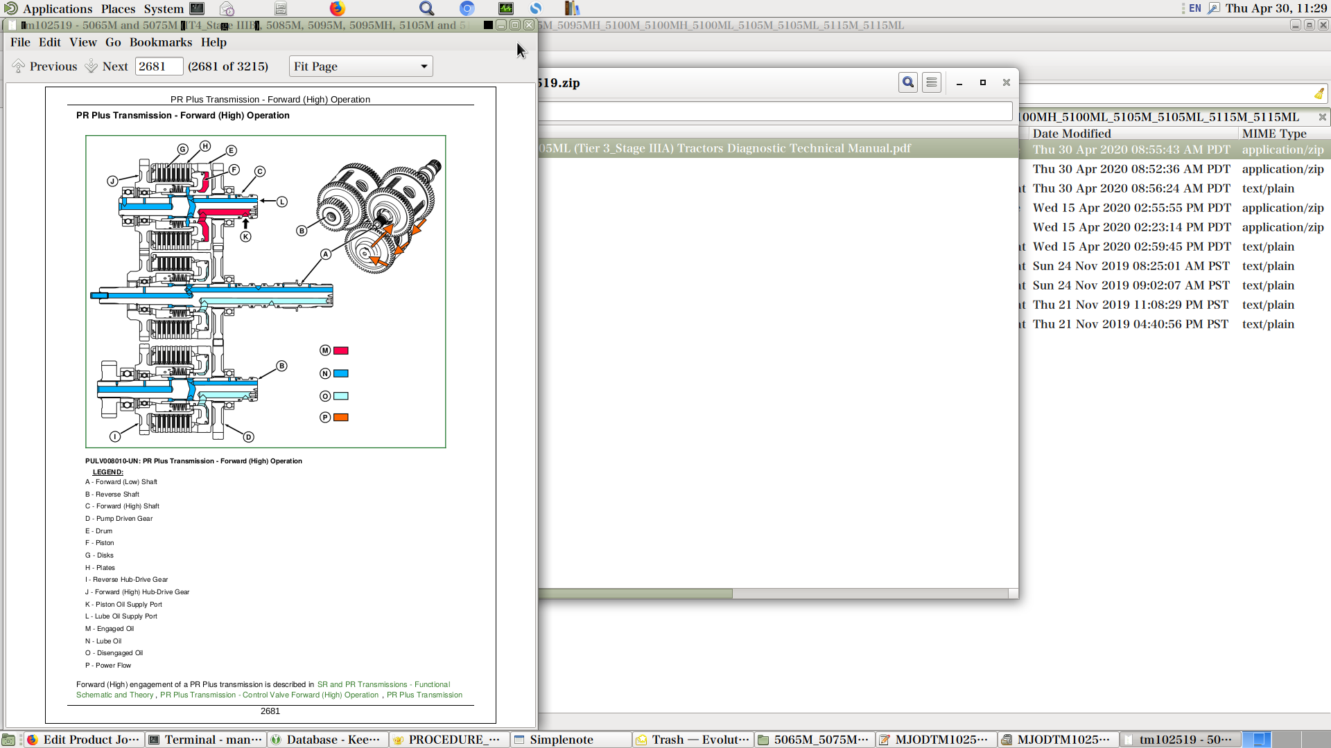
PR Plus Transmission - Forward (High) Operation
PR Plus Transmission - Reverse Operation
Section 256: Drive Systems
Group 10: Preliminary and Operational Checks
Drive Systems - Operational Check
Group 15: Tests and Adjustments
Drive Systems - Rear Differential Lock Leak Test
Drive Systems - MFWD Leak Test
Drive Systems - PTO Leak Test
Drive Systems - Differential Lube Pressure Test
Group 20: Theory of Operation
Drive Systems - Overview
Drive Systems - Functional Schematic
Drive Systems - Front Axle Operation
Drive Systems - MFWD Control Valve Operation
Drive Systems - MFWD Operation
Drive Systems - MFWD Power Flow Operation
Drive Systems - Rear Differential Lock Control Valve Operation
Drive Systems - Rear Differential Lock Operation
Drive Systems - Rear Differential Power Flow
Drive Systems - Rear Final Drive Operation
Drive Systems - Rear High Crop Differential and Final Drive Operation
Drive System - Rear Differential and Final Drive Lubrication
Drive Systems - Rear Power Take-Off Clutch Control Valve Operation
Drive Systems - Rear Power Take-Off Brake Control Valve Operation
Drive Systems - Rear Power Take-Off Operation
Drive Systems - Rear Power Take-Off Shift Operation
Drive Systems - Creeper Operation
Section 260: Steering and Brakes
Group 10: Preliminary and Operational Checks
Brakes - Preliminary Check
Brakes - Operational Test
Steering - Preliminary Check
Steering - Operational Check
Group 15: Test and Adjustments
Brakes - Brake Element Leak Isolation Test
Brakes - Brake Retractor Adjustment
Brakes - Secondary Brake Test
Brakes - Brake Valve Supply Test
Steering - Leak Test
Steering - Preliminary Supply Pressure Test
Steering - Steering Relief Pressure Test
Steering - Pump Flow Test
Group 20: Theory of Operation
Brakes - Brake Pistons, Plates, and Disks Theory of Operation
Brakes - Secondary Brakes Theory of Operation
Brakes - Brake Valve Theory of Operation
Brakes - Component Diagrams
Brakes - System Schematics
Steering - Component Diagrams
Steering - Gerotor Theory of Operation
Steering - Steering Pump Theory of Operation
Steering - Steering Valve Theory of Operation
Steering - Steering Valve with Anti-Cavitation and Surge Relief Valves - Theory of Operation
Steering - Steering Valve Component Theory of Operation
Steering - System Schematics
Section 270: Hydraulics
Group 10: Preliminary and Operational Checks
Hydraulics - Preliminary Check
Hydraulics - Operational Check
Hydraulics - Rear Hitch System Operational Check
Hydraulics - Hydraulic Trailer Brake System Operational Check
Group 15: Tests and Adjustments
Hydraulics - Heating Hydraulic Oil
Hydraulics - Hitch Cylinder Supply Pressure Test
Hydraulics - Hitch Load-Sense Relief Valve Adjustment
Hydraulics - Hitch Surge Relief Valve Test
Hydraulics - Hydraulic Trailer Brake Valve Test
Hydraulics - Implement Pump Flow Test
Hydraulics - Implement Relief Valve Adjustment
Hydraulics - Kick-Out Detent Pressure Test
Hydraulics - Main Relief Valve Test
Hydraulics - SCV Leak Down Test
Group 20A: Theory of Operation
Hydraulics - Overview
Hydraulics - Functional Schematic ( –Dec. 2011)
Hydraulics - Functional Schematic (Dec. 2011–Oct. 2015)
Hydraulics - Functional Schematic (Oct. 2015– )
Hydraulics - Main Hydraulic Filter Operation
Hydraulics - Hydraulic Pump Operation
Hydraulics - Hydraulic Trailer Brake Operation
Hydraulics - Mechanical Hitch Control Valve Lower Operation ( –Dec. 2011)
Hydraulics - Mechanical Hitch Control Valve Lower Operation (Dec. 2011– )
Hydraulics - Mechanical Hitch Control Valve Neutral Operation ( –Dec. 2011)
Hydraulics - Mechanical Hitch Control Valve Neutral Operation (Dec. 2011– )
Hydraulics - Mechanical Hitch Control Valve Raise Operation ( –Dec. 2011)
Hydraulics - Mechanical Hitch Control Valve Raise Operation (Dec. 2011– )
Hydraulics - Mechanical Hitch Implement Relief Valve Operation
Hydraulics - Mechanical Hitch Rate-of-Drop Valve Operation
Hydraulics - Mechanical Hitch Lower Link Draft-Sensing Operation
Hydraulics - Electro-Hydraulic Hitch Control Valve Lower Operation
Hydraulics - Electro-Hydraulic Hitch Control Valve Neutral Operation
Hydraulics - Electro-Hydraulic Hitch Control Valve Raise Operation
Hydraulics - Electro-Hydraulic Hitch Main Relief Valve Operation
Hydraulics - Quick Disconnect Coupler Operation
Group 20B: Theory of Operation—Mono Block SCV Valves
Hydraulics - Dual Mid-Mount SCV Extend and Retract Operation ( –Oct. 2015)
Hydraulics - Dual Mid-Mount SCV Float Operation ( –Oct. 2015)
Hydraulics - Dual Mid-Mount SCV Neutral Operation ( –Oct. 2015)
Hydraulics - Dual Mid-Mount SCV Regenerative Operation ( –Oct. 2015)
Hydraulics - Triple Mid-Mount SCV Extend and Retract Operation ( –Oct. 2015)
Hydraulics - Triple Mid-Mount SCV Neutral Operation ( –Oct. 2015)
Hydraulics - Triple Mid-Mount SCV Float Operation ( –Oct. 2015)
Hydraulics - Triple Mid-Mount SCV Flow Control Valve Operation ( –Oct. 2015)
Hydraulics - Single and Dual Rear SCV Extend and Retract Operation ( –Oct. 2015)
Hydraulics - Single and Dual Rear SCV Float Operation ( –Oct. 2015)
Hydraulics - Single and Dual Rear SCV Neutral Operation ( –Oct. 2015)
Hydraulics - Triple Rear SCV Extend and Retract Operation ( –Oct. 2015)
Hydraulics - Triple Rear SCV Float Operation ( –Oct. 2015)
Hydraulics - Triple Rear SCV Neutral Operation ( –Oct. 2015)
Hydraulics - Triple Rear SCV Continuous Detent Operation ( –Oct. 2015)
Hydraulics - Triple Rear SCV Kick-Out Detent Operation ( –Oct. 2015)
Hydraulics - Triple Rear SCV No Detent Operation ( –Oct. 2015)
Hydraulics - Triple Rear SCV Priority Flow Control Valve Operation ( –Oct. 2015)
Hydraulics - Power Beyond Operation ( –Oct. 2015)
Hydraulics - SCV Diverter Plug Operation ( –Oct. 2015)
Group 20C: SCV Theory of Operation—Sectional Valves
Hydraulics - Dual Mid-Mount SCV Neutral Operation (Oct. 2015– )
Hydraulics - Dual Mid-Mount SCV Extend and Retract Operation (Oct. 2015– )
Hydraulics - Dual Mid-Mount SCV Float Operation (Oct. 2015– )
Hydraulics - Triple Mid-Mount SCV Neutral Operation (Oct. 2015– )
Hydraulics - Triple Mid-Mount SCV Extend and Retract Operation (Oct. 2015– )
Hydraulics - Triple Mid-Mount SCV Float Operation (Oct. 2015– )
Hydraulics - Triple Mid-Mount SCV Flow Control with Pressure Compensator Valve Operation (Oct. 2015– )
Hydraulics - Dual Rear SCV Neutral Operation (Oct. 2015– )
Hydraulics - Dual Rear SCV Extend and Retract Operation (Oct. 2015– )
Hydraulics - Dual Rear SCV Float Operation (Oct. 2015– )
Hydraulics - Triple Rear SCV Neutral Operation (Oct. 2015– )
Hydraulics - Triple Rear SCV Float Operation (Oct. 2015– )
Hydraulics - Triple Rear SCV Continuous Detent Operation (Oct. 2015– )
Hydraulics - Triple Rear SCV Kick-Out Detent Extend Operation (Oct. 2015– )
Hydraulics - Triple Rear SCV No Detent Retract Operation (Oct. 2015– )
Hydraulics - Triple Rear SCV Flow Control with Pressure Compensator Valve Operation (Oct. 2015– )
Hydraulics - Power Beyond Operation (Oct. 2015– )
Section 290: Operator Station
Group 10: Preliminary and Operational Checks
Operator Station - HVAC Preliminary Checks
Operator Station - HVAC Operational Checks
Group 15: Tests and Adjustments
Operator Station - A/C System Pressure Test
Operator Station - A/C System Static Pressure Test
Operator Station - Temperature Drop Test
Group 20: Theory of Operation
Operator Station - Air Conditioning System Operation
Operator Station - Air Conditioning System Operation (Dec. 2011– )
Operator Station - Air Conditioning Compressor Operation
Operator Station - Air Conditioning Condenser Operation
Operator Station - Air Conditioning Dual Pressure Switch Operation
Operator Station - Air Conditioning Evaporator Operation
Operator Station - Air Conditioning Expansion Valve Operation
Operator Station - Air Conditioning Receiver/Dryer Operation
Operator Station - Air Conditioning Temperature Control Switch Operation
Operator Station - Air Conditioning ON/OFF Switch and Temperature Control Knob Operation
Operator Station - Heater Temperature Control Knob Operation
Operator Station - Air Seat Operation
Operator Station - Mechanical Seat Operation
Operator Station - Heating and Ventilation Operation
Section 299: Service Tools and Installing Test Equipment
Group 05: Dealer Fabricated Tools
DFRW26 — Test Lead For Automotive-Style Fuses
DFRW51—Electronic Circuit Load Tester
DFRW126—Modified Tap Out Harness
DFRW133 — Tap Out Harness
DFRW183—Coupler DR Assembly
DFRW213 — Hydraulic Trailer Brake Test / Bleed Assembly
DFRW221 — Lube Pressure Gauge Assembly
DFRW229 — Test Hose
Group 10: Service Tools and Kits
38H1029 — Tee (-4 ORFS)
38H1145 — Plug (-4 ORFS)
38H1147 — Plug (-8 ORFS)
38H1149 — -12 ORFS Plug
38H1279 — Union (-8 ORFS)
38H1414 — Cap (-4 ORFS)
38H1415 — Cap (-6 ORFS)
38H1416 — Cap (-8 ORFS)
38H5003 — Straight Fitting (-8 (m) ORFS x M18 x 1.5 (m))
38H5067—Tee Fitting (-6 (m) ORFS x M14 (m) x -6 (m) ORFS)
AR52361 — Quick Connect Coupler
JDG11863— Hydraulic Tester
D05330ST — Supplemental Accessory Kit
D15032NU — Vacuum Pump Kit
FKM10002 — Pressure Gauge Set
FKM10302 — Connector
FKM10303 — Connector
FKM10305 — Connector
JDG774 — Solenoid Test Harness
JDG774A — Solenoid Test Harness
JDG1478—Digital Multimeter
JDG10466 — Flex Probe Kit
JDG10940 — Transmission Top Shaft Socket
JT01767 — Supplemental Lawn and Grounds Care Products Hydraulic Fitting Kit
JT02051 — Manifold With Vibration Free Gauges
JT02063 — Electronic Leak Detector
JT02153 — Current Clamp-On Probe
JT02178 — A/C Leak Detection Kit
JT02180 — A/C Leak Detector Kit
JT03043—Straight Fitting (1/2 NPT 30° Chamfer x 1-1/16-12 (m) JIC)
JT03105 — Connector (1/2 (m) NPT X 1/4 (f) NPT)
JT03261 — Coupler (1/4 (m) NPT)
JT03348 — Tee Fitting (1/2 (f) NPT x 1/2 (f) NPT x 1/2 (f) NPT)
JT03477 - MALE QUICK COUPLER x -4 F ORFS
JT03478 — Male Quick Coupler x -6 ORFS
JT03479 — Male Quick Coupler x -8 ORFS
JT05406 — Master Hydraulic Fitting Flow Test Kit
JT05412 — Industrial Universal Pressure Test Kit
JT05418 — Industrial Flow Test Kit
JT05470 — Universal Pressure Test Kit
JT05471 — Gauge w/Quick Coupler, 7000 kPa (70 bar) (1000 psi)
JT05473 — Gauge w/Quick Coupler, 35,000 kPa (350 bar) (5,000 psi)
JT05474 — Gauge w/Quick Coupler 2,000 kPa (20 bar) (300 psi)
JT05480 — Diagnostic Receptacle (M14 x 1.5M ORB x 1/2 Quick Coupler)
JT05497 — Hose Assembly, 3048 mm (120 in.) Long
JT05498 — Hose Assembly, 482.6 mm (19 in.) Long
JT05685 — Battery Load Tester
JT05832 — Battery Load Tester
JT05833 — Battery Service Kit
JT05843 — Hydrometer
JT05845 — 2-Speed Hand Pump
JT07115 — Master Hydraulic Test Kit
JT07115 SUP — Supplemental Master Hydraulic Test Kit
JT07117 — Three-Gauge Manifold
JT07118 — Two-Valve Manifold
JT07119 — 5 ft. Test Hose
JT07207 — 500 kPa (5 bar) (200 psi) Gauge
JT07209 — Hydraulic Test Kit
JT07212 — Diagnostic Fitting Kit
JT07253 — Non-Contact Temperature Measuring Gun
KJD10128 — Adaptor Fitting
RE43774 — Diagnostic Receptacle (13/16-16 (f) ORFS)
RE60701 — Diagnostic Receptacle (-6 ORFS)
Group 50: Transmission — Install Test Equipment
Install Test Equipment 50-1
Install Test Equipment 50-2
Install Test Equipment 50-3
Install Test Equipment 50-4
Install Test Equipment 50-5
Install Test Equipment 50-6
Install Test Equipment 50-7
Install Test Equipment 50-8
Install Test Equipment 50-9
Install Test Equipment 50-10
Install Test Equipment 50-11
Install Test Equipment 50-12
Install Test Equipment 50-13
Install Test Equipment 50-14
Install Test Equipment 50-15
Group 56: Drive Systems — Install Test Equipment
Install Test Equipment 56-1
Install Test Equipment 56-2
Install Test Equipment 56-3
Install Test Equipment 56-4
Install Test Equipment 56-5
Install Test Equipment 56-6
Install Test Equipment 56-7
Group 60: Steering and Brakes — Install Test Equipment
Install Test Equipment 60-2
Install Test Equipment 60-3
Install Test Equipment 60-4
Install Test Equipment 60-5
Install Test Equipment 60-6
Install Test Equipment 60-7
Install Test Equipment 60-8
Group 70: Hydraulics — Install Test Equipment
Install Test Equipment 70-1
Install Test Equipment 70-2
Install Test Equipment 70-3
Install Test Equipment 70-4
Install Test Equipment 70-5
Install Test Equipment 70-6
Install Test Equipment 70-7
Install Test Equipment 70-8
Install Test Equipment 70-9
Group 90: Operator Station — Install Test Equipment
Install Test Equipment 90-1
John Deere Tractors 5105ML, 5095MH, 5095M, 5085M, 5075M, 5065M Diagnosis and Tests Service Technical Manual (TM102519)
![]()