
John Deere Tractors Models 5415, 5615, 5715 Repair Service Manual (TM606719)
Complete Repair Service Technical Manual for John Deere Tractors Models 5415, 5615, 5715 (April 2013), with workshop information to maintain, service, repair, and rebuild like professional mechanics.
John Deere Tractors Models 5415, 5615, 5715 workshop technical manual (repair) includes:
* Numbered table of contents easy to use so that you can find the information you need fast.
* Detailed sub-steps expand on repair procedure information
* Numbered instructions guide you through every repair procedure step by step.
* Troubleshooting and electrical service procedures are combined with detailed wiring diagrams for ease of use.
* Notes, cautions and warnings throughout each chapter pinpoint critical information.
* Bold figure number help you quickly match illustrations with instructions.
* Detailed illustrations, drawings and photos guide you through every procedure.
* Enlarged inset helps you identify and examine parts in detail.
tm606719 - 5415, 5615, and 5715 Tractors (April 2013) Technical Manual.pdf
tm606719 - 5415, 5615, and 5715 Tractors (April 2013) Technical Manual.epub
Total Pages: 742 pages
File Format: PDF/EPUB/MOBI/AZW (PC/Mac/Android/Kindle/iPhone/iPad; bookmarked, ToC, Searchable, Printable)
Language: English
MAIN SECTIONS
Foreword
Version Date
Safety
Safety Measures
General Information
Specifications
Tune-Up
Predelivery Inspection
Engine
Engine Removal and Installation
Fuel, Air Intake, Cooling and Exhaust Systems
Speed Control Linkage
Fuel System
Air Intake System
Cooling System
Cold-Weather Starting Aid
Exhaust System
Electrical System
Connectors
Wiring Harnesses
Charging Circuit
Starting Motor Circuit
Fuses, Relays and Switches
Monitoring Systems
Electrical Components
PowrQuad and PowrQuad Plus Transmissions
Removal and Installation of Components
Transmission Shift Controls
PowrQuad Module
Reduction Gear
Range Transmission
Drive Systems
Removal and Installation of Components
U-Jointed Shafts and Torsion Damper
Front-Wheel Drive Clutch
Differential
Hydraulic Pump Drive
Final Drives
Rear PTO
Front PTO
Steering and Brakes
Hydrostatic Steering
Brake Valve
Rear Brakes
Handbrake
Hydraulic Trailer Brake
Air Brakes
Hydraulic System
Controls
Hydraulic Pump
Valves
Hitch
Selective Control Valves and Couplers
Miscellaneous
Removal and Installation of Components
Front and Rear Wheels
Trailer Mounting and Swinging Drawbar
Pick-Up Hitch
Front Hitch
Front Loader
Operator`s Cab
Removal and Installation of Components
Controls and Instruments
Air-Condtioning System
Heating System
Seats
Operator`s Cab
Parts for Electronic Hitch Control
Special Tools (Dealer-Fabricated)
Special Tools (Dealer-Fabricated)
Special Tools (available as spare parts)
tm606719 - 5415, 5615, and 5715 Tractors (April 2013)
Table of Contents
Foreword
Section 10: General Information
Group 05: Safety
Recognize Safety Information
Understand Signal Words
Follow Safety Instructions
Prepare for Emergencies
Wear Protective Clothing
Protect Against Noise
Handle Fuel Safely—Avoid Fires
Handle Starting Fluid Safely
Fire Prevention
In Case of Fire
Keep ROPS Installed Properly
Use Foldable ROPS and Seat Belt Properly
Stay Clear of Rotating Drivelines
Use Steps and Handholds Correctly
Read Operator Manuals for ISOBUS Implements
Use Seat Belt Properly
Operating the Tractor Safely
Avoid Backover Accidents
Limited Use in Forestry Operation
Operating the Loader Tractor Safely
Keep Riders Off Machine
Instructional Seat
Use Safety Lights and Devices
Use a Safety Chain
Transport Towed Equipment at Safe Speeds
Use Caution On Slopes and Uneven Terrain
Freeing a Mired Machine
Avoid Contact with Agricultural Chemicals
Handle Agricultural Chemicals Safely
Handling Batteries Safely
Avoid Heating Near Pressurized Fluid Lines
Remove Paint Before Welding or Heating
Handle Electronic Components and Brackets Safely
Practice Safe Maintenance
Avoid Hot Exhaust
Clean Exhaust Filter Safely
Work In Ventilated Area
Support Machine Properly
Prevent Machine Runaway
Park Machine Safely
Transport Tractor Safely
Service Cooling System Safely
Service Accumulator Systems Safely
Service Tires Safely
Service Front-Wheel Drive Tractor Safely
Tightening Wheel Retaining Bolts/Nuts
Avoid High-Pressure Fluids
Do Not Open High-Pressure Fuel System
Store Attachments Safely
Dispose of Waste Properly
Group 10: General Specifications
Machine Specifications
Machine Specifications, Continued
Machine Specifications, Continued
Machine Specifications, Continued
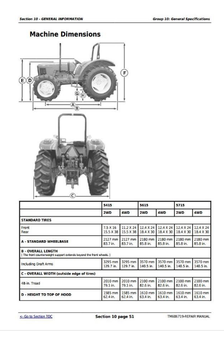
Machine Dimensions
Maximum Permissible Load Specifications
Estimated Vehicle Speed, Synchronized Transmissions (PY)
Repair Specifications
Repair Specifications - Cont..
Repair Specifications - Cont..
Repair Specifications - Cont..
Repair Specifications - Cont..
Repair Specifications - Cont..
Repair Specifications - Cont..
Repair Specifications - Cont..
Repair Specifications - Cont..
Service Recommendations for O-Ring Boss Fittings
Service Recommendations for Flat Face O-Ring Seal Fittings
Metric Cap Screw Torque Values—Grade 7
Metric Bolt and Screw Torque Values
Unified Inch Bolt and Screw Torque Values
Abbreviations
Group 20: Fuel and Lubricants
Diesel Fuel Specifications
Lubricity of Diesel Fuel
Diesel Fuel Storage
Do Not Use Galvanized Containers
Fill Fuel Tank
Diesel Engine Oil
Heavy Duty Diesel Engine Coolant
Engine Break - In Oil
Engine Cooling System
Liquid Coolant Conditioner
Transmission and Hydraulic Oil
MFWD Gear Oil
Grease (Specific Application)
Grease
Alternative and Synthetic Lubricants
Lubricant Storage
Group 25: Serial Number Locations
Serial Numbers
Product Identification Number Location
Engine Serial Number Location
Fuel injection pump serial number location
Alternator Identification Number Location
Power Steering Valve Serial Number Location
Transmission Serial Number Location
Front Axle (2WD) Serial Number Location
Mechanical Front Wheel Drive (MFWD) Serial Number Location
Group 30: Features and Accessories
Features and Accessories
Standard Features
Standard Features
Operating Foldable Rops
Fixed ROPS Crossbar
Factory Installed Optional Equipment
Field Installed Optional Kits and Accessories
Section 20: Engine Repair
Group 05: Engine
Service Equipment and Tools
Specifications
John Deere Engine Repair—Use Component Technical Manual
Remove Engine
Install Engine
Group 10: Cooling System
Specifications
Engine Coolant Pump Repair—Use Component Technical Manual
Remove right-side fan guard (Serial Number -XXXXXX)
Remove right-side fan guard (Serial Number XXXXXX-)
Remove left-side fan guard (Serial Number -XXXXXX)
Remove left-side fan guard (Serial Number XXXXXX-)
Remove and Install Coolant Recovery Tank (Serial Number -XXXXXX)
Remove and Install Coolant Recovery Tank (Serial Number XXXXXX-)
Remove and Inspect Radiator
Install Radiator
Remove and Install Thermostat
Inspect and Replace Belt Tensioner
Section 30: Fuel System
Group 05: Fuel System
Injection Pump, Nozzle and Governor Repair—Use Component Technical Manual
Remove, Inspect and Install Fuel Tank—Reference Listing
Remove, Inspect and Install Fuel Tank (Serial Number -XXXXXX)
Remove, Inspect and Install Fuel Tank (Serial Number XXXXXX-)
Replace Fuel Filter (Engine Tier 0 and 1)
Remove and Install Fuel Filter/Primer Pump Assembly (Engine Tier 0 and 1)
Remove and Install The Water Separator Assembly
Group 10: Air Intake System
Turbocharger Repair—Use Component Technical Manual
Specifications
Other Material
Remove, Inspect, and Install Air Cleaner Elements
Remove Turbocharger
Install Turbocharger
Turbocharger Break-In
Group 15: Speed Control Linkage
Inspect and Repair Speed Control Linkage—Reference Listing
Inspect and Repair Speed Control Linkage (OOS)
Section 40: Electrical Repair
Group 05: Battery, starter and alternator
Starter Repair—Use Component Technical Manual—PowerTech 4.5L Diesel Engine Base Engine
Prevent Battery Explosions
Remove and Install Battery
Remove and Install Starter
Replace Alternator/Regulator
Group 10: Electrical system components
Essential Tools
Other Material
Specifications
Replace Air Filter Restriction Switch
Replace Cold Start Advance Switch
Replace Coolant Temperature Sender
Replace Engine Speed Sensor
Replace Engine Oil Pressure Switch
Replace Key Switch—Reference Listing
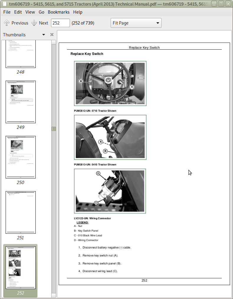
Replace Key Switch
Replace Light Switch
Replace Turn Signal Switch—Reference Listing
Replace Turn Signal Switch
Replace Instrument Panel—Reference Listing
Replace Instrument Panel
Replace Rear PTO Switch—Reference Listing
Replace Rear PTO Switch—OOS
Replace Neutral Start Switch
Replace Fuel Level Sender—Reference Listing
Replace Fuel Level Sender— (Serial number -XXXXXX)
Replace Fuel Level Sender— (Serial number XXXXXX-)
Replace Seat Switch—Reference Listing
Replace Seat Switch—OOS (if equipped)
Replace Start Relay
Group 15: Wiring Harness
Service Equipment and Tools
Essential Tools
Service Parts Kits
Replace Connector Body—Blade Terminals
Replace WEATHER PACK WEATHER PACK is a trademark of Packard Electric. Connector
Install WEATHER PACK WEATHER PACK is a trademark of Packard Electric. Contact
Repair (Pull Type) Metri-Pack® Connectors
Repair (Push Type) Metri-Pack® Connectors
Replace Front Wiring Harness—(Serial number -XXXXXX)
Replace Hood Wiring Harness (Serial Number XXXXXX-)
Replace Battery Cable
Replace Engine Wiring Harness
Replace Wiring Harness—, Synchronized Transmission
Replace 7 Pin Connector Wiring Harness
Replace Rear Wiring Harness—(Serial number -XXXXXX)
Section 50: Power Train Repair
Group 05: Clutch Housing
Service Equipment and Tools
Other Material
Specifications
Separate Engine from Clutch Housing—Reference Listing
Separate Engine from Clutch Housing
Install Engine to Clutch Housing—Reference Listing
Install Engine to Clutch Housing
Inspect and Repair Clutch Pedal and Linkage—Reference Listing
Inspect and Repair Clutch Pedal and Linkage (OOS)
Group 10: Clutch Assembly
Essential Tools
Service Equipment and Tools
Other Material
Specifications
Remove and Install Clutch Assembly
Disassemble and Inspect Clutch Assembly
Assemble Clutch Assembly
Traction Clutch Finger Adjustment
PTO Clutch Finger Adjustment
Remove and Inspect Clutch Release Mechanism and Shafts
Install Clutch Release Mechanism and Shafts
Group 15: Synchronized Transmission
John Deere Transmission Repair—Use CTM
Separate Clutch Housing from Transmission—Reference Listing
Separate Clutch Housing from Transmission—(Serial Number -XXXXXX)
Separate Clutch Housing from Transmission — Serial Number XXXXXX-)
Install Clutch Housing to Transmission—Reference Listing
Install Clutch Housing to Transmission—(Serial Number -XXXXXX)
Install Clutch Housing to Transmission — (Serial Number XXXXXX-)
Inspect and Repair Gear Shift Lever—Reference Listing
Inspect and Repair Gear Shift Lever (RH)
Inspect and Repair Range Shift Lever (LH)
Inspect and Repair Gear and Range Shift Levers (RH)
Remove Transmission—Reference Listing
Remove Transmission
Install Transmission—Reference Listing
Install Transmission
Inspect and Repair Park Brake Lever (if equipped)
Remove, Inspect, and Repair Park Brake (if equipped)
Group 20: Rear PTO Drive Shaft
John Deere Transmission Repair—Use CTM
Inspect and Repair Rear PTO Lever and Linkage—Reference Listing
Inspect and Repair Rear PTO Lever and Linkage (OOS)
Group 25: Differential
John Deere Transmission Repair—Use CTM
Remove, Inspect, and Install Differential Lock Assembly—Reference Listing
Remove, Inspect, and Install Differential Lock Assembly (OOS)
Group 30: Final Drive
Service Equipment and Tools
Other Material
Remove and Install Final Drive Assembly—Reference Listing
Remove and Install Final Drive Assembly
Remove and Inspect Planetary Drive Assembly
Install Planetary Drive Assembly
Remove, Inspect, and Install Axle Shaft Assembly
Group 35: Mechanical Front Wheel Drive
Special or Essential Tools
Tools
Other Material
Inspect and Repair MFWD Lever and Linkage—Reference Listing
Inspect and Repair MFWD Lever and Linkage (OOS)
Remove and Install MFWD Drop Gearbox
Disassemble and Inspect MFWD Drop Gearbox
MFWD Drop Gearbox Cross Section
Assemble MFWD Drop Gearbox
Remove, Inspect and Install MFWD Drive Shaft—Reference Listing
Remove, Inspect and Install MFWD Drive Shaft
Remove and Install MFWD Axle Housing Assembly—Reference Listing
Remove and Install MFWD Axle Housing Assembly
Remove, Inspect and Install MFWD Axle Supports—Reference Listing
Remove, Inspect and Install MFWD Axle Supports
Disassemble and Inspect MFWD Outer Drive—Reference Listing
Disassemble and Inspect MFWD Outer Drive
Assemble MFWD Outer Drive—Reference Listing
Assemble MFWD Outer Drive
Remove, Inspect and Install MFWD Knuckle Housing—Reference Listing
Remove, Inspect and Install MFWD Knuckle Housing
Remove, Inspect, and Install MFWD Axle Shaft—Reference Listing
Remove, Inspect, and Install MFWD Axle Shaft
Remove and Install MFWD Differential Carrier Assembly
Disassemble and Inspect MFWD Differential Carrier Assembly
Assemble MFWD Differential Carrier Assembly
Filling/Draining Planetary Drive
Filling/Draining MFWD Axle Housing
Group 40: Creeper Assembly
Other Material
Remove and Install Creeper Assembly
Disassemble, Inspect, and Assemble Creeper Assembly
Section 60: Steering and Brake Repair
Group 05: Steering Repair
Other Material
Specifications
Service Parts Kits
Remove and Install Steering Column and Valve—Reference Listing
Remove and Install Straight Steering Column and Valve (without oil cooler)
Remove and Install Tilt Steering Column (if equipped)
Remove and Install Steering Valve (with oil cooler)
Disassemble and Inspect Steering Valve
Assemble Steering Valve
Remove and Install Steering Cylinder—Reference Listing
Remove and Install Steering Cylinder—2WD Axle
Disassemble, Inspect, and Assemble Steering Cylinder—Reference Listing
Disassemble, Inspect, and Assemble Steering Cylinder—2WD Axle
Remove and Install Steering Cylinder—MFWD Axle—Reference Listing
Remove and Install Steering Cylinder—MFWD Axle
Disassemble, Inspect, and Assemble Steering Cylinder—MFWD Axle—Reference Listing
Disassemble, Inspect, and Assemble Steering Cylinder—MFWD Axle
Remove, Inspect and Install Tie Rod Assembly—2WD Axle—Reference Listing
Remove, Inspect and Install Tie Rod Assembly—2WD Axle
Remove, Inspect and Install Tie Rod Assembly—MFWD Axle—Reference Listing
Remove, Inspect and Install Tie Rod Assembly—MFWD Axle
Inspect and Replace Steering Hydraulic Lines—Reference Listing
Inspect and Replace Steering Hydraulic Lines—without oil cooler (5415)
Inspect and Replace Steering Hydraulic Lines—with oil cooler (5615 and 5715)
Steering Hydraulic Lines—with oil cooler (5615 and 5715)
Group 10: Brake Repair
Other Material
Remove and Install Brake Valve and Pedals
Disassemble and Inspect Brake Valve
Brake Valve Cross Section
Assemble Brake Valve
Remove and Inspect Brakes
Install Brakes
Inspect and Replace Brake Hydraulic Lines
Section 70: Hydraulic Repair
Group 05: Hydraulic pump and filter
Service Parts Kit
Service Equipment and Tools
Specifications
Remove, Inspect, and Install Hydraulic Oil Pick-Up Screen
Remove and Install Hydraulic Pump
Remove Hydraulic Pump External Components
Disassemble and Inspect Hydraulic Pump
Assemble Hydraulic Pump
Install Hydraulic Pump External Components
Remove and Install Hydraulic Oil Filter/Manifold
Inspect and Replace Hydraulic Supply/Return Lines
Group 06: Hydraulic Oil Cooler
Remove, Inspect, and Install Hydraulic Oil Cooler—Reference Listing
Remove, Inspect, and Install Hydraulic Oil Cooler
Group 10: Rockshaft
Other Material
Service Parts Kits
Inspect and Repair Rockshaft Control Lever Assembly—Reference Listing
Inspect and Repair Rockshaft Control Lever Assembly
Inspect and Repair Rockshaft Control Linkage
Inspect and Repair Draft Sensing Support Assembly
Replace Main Relief Valve
Replace Rockshaft Surge Relief Valve
Remove, Inspect, and Install Rate-of-Drop Valve
Replace Rockshaft Control Valve
Remove and Install Rockshaft Case
Remove, Inspect, and Install Rockshaft Lift Arms
Remove, Inspect, and Install Rockshaft Piston and Cylinder
Group 15: Dual Selective Control Valve
Other Material
Service Parts Kits
Remove and Install Dual Selective Control Valve (SCV)
Disassemble, Inspect, and Assemble Dual Selective Control Valve (SCV)
Inspect and Replace Hydraulic Hoses—Dual Selective Control Valve (SCV)
Group 16: Single Selective Control Valve
Other Material
Service Parts Kits
Inspect and Repair SCV Levers and Linkage (OOS)
Remove and Install Single Selective Control Valve (SCV)—Reference Listing
Remove and Install Single Selective Control Valve (SCV)
Disassemble, Inspect and Assemble Single (Third) Selective Control Valve (SCV)—Reference Listing
Disassemble, Inspect, and Assemble Single (Third) Selective Control Valve (SCV)
Inspect and Replace Hydraulic Hoses—Single (Third) Selective Control Valve (SCV)
Group 20: Hydraulic Power Beyond
Remove and Install Hydraulic Lines and Fittings—Power Beyond Hook-Up—Reference Listing
Remove and Install Hydraulic Lines and Fittings—Power Beyond Hook-Up
Section 80: Miscellaneous Repair
Group 05: Front Axle—2WD
Remove and Install Front Axle—2WD—Reference Listing
Remove and Install Front Axle—2WD
Inspect and Replace Pivot Pin and Bushings—2WD Axle
Remove and Install Spindle Assembly—2WD Axle—Reference Listing
Remove and Install Spindle Assembly—2WD Axle
Inspect and Replace Spindle Shaft Bushings—2WD Axle
Group 10: Wheels
Inspect and Replace Front Wheel Bearings—Reference Listing
Inspect and Replace Front Wheel Bearings - 2WD
Group 15: 3-Point Hitch
Inspect and Repair Draft Links—Reference Listing
Inspect and Repair Fixed Draft Links (if equipped with sway chain)
Inspect and Repair Lift Link—Reference Listing
Inspect and Repair Standard Lift Link
Inspect and Repair Adjustable Lift Link
Inspect and Repair Center Link—Reference Listing
Inspect and Repair Center Link
Remove and Install Drawbar and Support—Reference Listing
Remove and Install Drawbar and Support
Drawbar and Support (Continued)
Group 20: Fenders
Remove and Install Fenders—Reference Listing
Remove and Install Fenders—(Serial Number -XXXXXX)
Remove and Install Fenders (Serial Number XXXXXX-)
Group 25: Hood
Remove and Install Hood
Section 90: Operator Station Repair
Group 05: Seat and Support
Remove and Install Seat and Support—Reference Listing
Remove and Install Seat and Support—OOS
Group 06: Control Console and Panel
Remove and Install Right-Side Control Console and Panel (Serial Number -XXXXXX)
Remove and Install Right-Side Control Console and Panel (Serial Number XXXXXX-)
Remove and Install Left-Side Control Console and Panel (Serial Number -XXXXXX)
Remove and Install Left-Side Control Console and Panel (Serial Number XXXXXX-)
Remove and Install Cowl Cover (Serial Number -XXXXXX)
Remove and Install Cowl Cover (Serial Number XXXXXX-)
Group 10: ROLL-GARD®
Remove and Install Roll-Gard™—Reference Listing
Remove and Install Roll-Gard™ (OOS)
Section 290: Dealer Fabricated Tools
Group 00: Dealer Fabricated Tools
PTO Clutch Finger Height Gauge
Traction Clutch Finger Height Gauge
Traction Clutch Finger Height Adjustment Tool
DFLV1A Final Drive Turning Tool
DFRW20—Compressor Holding Fixture
John Deere Tractors Models 5415, 5615, 5715 Repair Service Manual (TM606719)
![]()