
John Deere Tractors 5620, 5720, 5820 Diagnostic and Repair Service Manual (TM4787)

Complete Repair Technical Manual for John Deere Tractors 5620, 5720, 5820 (2WD / MFWD), with all the service information to repair, and service like professional mechanics.
John Deere 5620, 5720 and 5820 (2WD or MFWD) Tractors workshop repair technical manual includes:
* Numbered table of contents easy to use so that you can find the information you need fast.
* Detailed sub-steps expand on repair procedure information
* Numbered instructions guide you through every repair procedure step by step.
* Notes, cautions and warnings throughout each chapter pinpoint critical information.
* Bold figure number help you quickly match illustrations with instructions.
* Detailed illustrations, drawings and photos guide you through every procedure.
* Enlarged inset helps you identify and examine parts in detail.
TM4787 - John Deere 5620, 5720, 5820 Tractors Technical Manual (Repair).pdf
TM4787 - John Deere 5620, 5720, 5820 Tractors Technical Manual (Repair).epub
Total Pages: 1,518 pages
File Format: PDF/EPUB/MOBI/AZW (PC/Mac/Android/Kindle/iPhone/iPad; bookmarked, ToC, Searchable, Printable)
Language: English
MAIN SECTIONS
Foreword
Version Date
Safety
Safety Measures
General Information
Specifications
Tune-Up
Predelivery Inspection
Engine
Engine Removal and Installation
Fuel, Air Intake, Cooling and Exhaust Systems
Speed Control Linkage
Fuel System
Air Intake System
Cooling System
Cold-Weather Starting Aid
Exhaust System
Electrical System
Connectors
Wiring Harnesses
Charging Circuit
Starting Motor Circuit
Fuses, Relays and Switches
Monitoring Systems
Electrical Components
PowrQuad and PowrQuad Plus Transmissions
Removal and Installation of Components
Transmission Shift Controls
PowrQuad Module
Reduction Gear
Range Transmission
Drive Systems
Removal and Installation of Components
U-Jointed Shafts and Torsion Damper
Front-Wheel Drive Clutch
Differential
Hydraulic Pump Drive
Final Drives
Rear PTO
Front PTO
Steering and Brakes
Hydrostatic Steering
Brake Valve
Rear Brakes
Handbrake
Hydraulic Trailer Brake
Air Brakes
Hydraulic System
Controls
Hydraulic Pump
Valves
Hitch
Selective Control Valves and Couplers
Miscellaneous
Removal and Installation of Components
Front and Rear Wheels
Trailer Mounting and Swinging Drawbar
Pick-Up Hitch
Front Hitch
Front Loader
Operator's Cab
Removal and Installation of Components
Controls and Instruments
Air-Condtioning System
Heating System
Seats
Operator's Cab
Parts for Electronic Hitch Control
Special Tools (Dealer-Fabricated)
Special Tools (Dealer-Fabricated)
tm4787 - 5620, 5720 and 5820 Tractors
Table of Contents
Foreword
Version Date
Section 05: Safety
Group 05: Safety Measures
Recognize Safety Information
”Important” Information
”Note” Information
Prevent Machine Runaway
Handle Fluids Safely—Avoid Fires
Prevent Battery Explosions
Prepare for Emergencies
Prevent Acid Burns
Avoid High-Pressure Fluids
Service Cooling System Safely
Remove Paint Before Welding or Heating
Avoid Heating Near Pressurized Fluid Lines
Work In Ventilated Area
Wear Protective Clothing
Practice Safe Maintenance
Park Machine Safely
Use Proper Lifting Equipment
Construct Dealer-Made Tools Safely
Support Machine Properly
Work in Clean Area
Illuminate Work Area Safely
Service Machines Safely
Use Proper Tools
Service Tires Safely
Service Front-Wheel Drive Tractor Safely
Safety Information - Air Brake System
Avoid Eye Contact With Radar
Keep ROPS Installed Properly
Replace Safety Signs
Dispose of Waste Properly
Live With Safety
Safety Measures on Electronic Control Units
Section 10: General Information
Group 05: Specifications
Specifications (Summary of References)
Engine Specifications
Cooling System
Fuel Injection Pump (Stanadyne)
Air Intake System
Electrical System
Hydrostatic Steering
Clutch
PowrQuad and PowrQuad Plus Transmissions
Reduction Gear
Rear PTO
Front PTO
Differential
Differential Lock
Final Drives
Front-Wheel Drive
Hydraulic Brakes
Handbrake
Parking Lock
Hydraulic System with Gear-Driven Pump
Rockshaft
Front Hitch
Ground Travel Speeds
Front and Rear Wheels
Dimensions and Weights
Capacities
Handling and Storing Diesel Fuel
Diesel Fuel
Lubricity of Diesel Fuel
Diesel Engine Break-In Oil
Diesel Engine Oil
Transmission and Hydraulic Oil
Front-Wheel Drive Axle Oil
Diesel Engine Coolant
Supplemental Coolant Additives
Grease
Oil Filters
Mixing of Lubricants
Lubricant Storage
Operating in Warm Temperature Climates
Alternative and Synthetic Lubricants
Unified Inch Bolt and Screw Torque Values
Metric Bolt and Screw Torque Values
Hydraulic system inch fitting torques
Hydraulic system metric fitting torques
Installing Oil Hoses
Product-Identification Number
Engine Serial Number
Transmission Serial Number
Front-Wheel Drive Axle Serial Number
Sub-assembly serial numbers
Group 10: Tune-Up
Tune-Up (Summary of References)
Specifications
Using High-Pressure Washers
Preliminary Engine Test
Preliminary Fuel System Test
Clean Dust Unloading Valve
Engine Air Cleaner
Cleaning the Primary Filter Element
Cleaning a Dusty Element
Secondary (Safety) Element
Installing the Primary Filter Element
Check Air Intake System Connections for Leaks
Check Crankcase Vent Hose for Clogging
Clean the Radiator Grille Screen
Keep the Radiator Screen Clean
Check the Caps on the Expansion Tank
Check Radiator for Leaks
Check Engine Thermostat
Check Operation of Fuel Transfer Pump
Checking the Fuel Filter
Bleed Air from Fuel System
Clean the Water Trap
Run the engine until it is warm, and check engine speeds
Check Setting of Fuel Injection Pump
Check Setting of Speed Control Linkage
Clean the Battery, Cables and Battery Box with a Clean Cloth
Checking the Neutral Start Circuit
Check Operation of Starting Motor
Checking the lighting circuit
Final Engine Check
Tractor Operation Check
Group 15: Predelivery Inspection
Predelivery Inspection
Section 20: Engine
Group 00: Engine Removal and Installation
Special or Essential Tools
Specifications
Remove Engine
Install Engine
Section 30: Fuel, Air Intake, Cooling and Exhaust Systems
Group 05: Speed Control Linkage
Speed Control (Summary of References)
Adjust Hand Throttle Lever and Accelerator Pedal
Recondition Hand Throttle Lever and Accelerator Pedal
Group 10: Fuel System
Fuel System (Summary of References)
General Information
Remove Fuel Tank
Install Fuel Tank
Replace Fuel Gauge Sending Unit
Replace Primary Fuel Filter
Replace Fuel Transfer Pump
Change Fuel Filter
Replacing the Check Valve in the Fuel Line
Replacing the Adapter in the Fuel Line
Bleed Air from Fuel System
Group 15: Air Intake System
Air Intake System (Summary of References)
General Information
Check Dust Unloading Valve
Remove and Install the Air Cleaner Element
Remove and Install Air Intake Hoses
Replace Sending Unit for Air Cleaner Restriction (B02)
Group 20: Cooling System
Cooling System (Summary of References)
General Information
Specifications
Remove and Install Radiator
Change Viscous Clutch of Fan
Remove and Install Thermostat and Temperature Sensor
Fill Cooling System with Coolant
Relieve Tension on Drive Belt
Replace Drive Belt
Replace Drive Belt Tensioner
Recondition Fan Console
Group 25: Cold-Weather Starting Aid
Fuel Preheater
Electrical Starting Aid
Coolant Heater
Group 30: Exhaust System
Exhaust System (Summary of References)
General Information
Exhaust System — Install Muffler (Tractor without Turbocharger)
Exhaust System — Install Muffler (Tractor with Turbocharger)
Exhaust System — Exhaust Pipe on Right of Cab Frame
Exhaust System — Exhaust Pipe to Top Right (Upright)
Exhaust System — Exhaust Pipe to Bottom Right
Section 40: Electrical System
Group 05: Connectors
Connectors - Reconditioning (Summary of References)
Special Tools
General
Using high-pressure washers
Disconnecting electrical circuits
Stripping Wire Ends
Installing a Terminal
METRI PACK Connector with Terminal Lock at the Rear
METRI PACK Connectors
Connectors for Electronic Control Units
Connectors
CRIMP SNAP IN connectors
DEUTSCH Connectors
Individual Terminals
Fuse and Relay Boxes
Group 10: Wiring Harnesses
Wiring Harnesses for Tractors with PowrQuad Transmission - Reconditioning (Summary of References)
Wiring Harnesses for Tractors with PowrQuad Transmission from Serial No. 436758 - Reconditioning (Summary of References)
Wiring Harnesses for Tractors with PowrQuad Plus Transmission - Reconditioning (Summary of References)
Wiring Harnesses for Tractors with PowrQuad Plus Transmission from Serial No. 434662 - Reconditioning (Summary of References)
Ground Point Locations
Remove and Install Harness W01 — Power Supply and Starting Aid
Remove and Install Harness W01 — Power Supply and Starting Aid from Serial No. 436764
Remove and Install Harness W02 — Engine
Remove and Installing Harness W04 — Headlights
Remove and Install Harness W07 — Front PTO
Remove and Install Harness W08 — Cab, for Tractors with PowrQuad Transmission
Remove and Install Harness W08 — Cab, for Tractors with PowrQuad transmission from Serial No. 436758
Remove and Install Harness W08 — Cab, for Tractors with PowrQuad Plus Transmission
Remove and Install Harness W08 — Cab, for Tractors with PowrQuad Plus transmission from Serial No. 434662
Remove and Install Harness W13 — Clutch Sender
Remove and Install Harness W14 — 3-Terminal Power Outlet Socket
Remove and Install Harness W18 — Windshield Wiper Switch (without Intermittent Wipe)
Remove and Install Harness W18 — Windshield Wiper Switch (with Intermittent Wipe)
Remove and Install Harness W19 — Cab Roof and Fan
Remove and Install Harness W20 — Turn Signal and Clearance Lights
Remove and Install Harness W21 — Adapter for Worklights on Cab Roof
Remove and Install Harness W23 — Windshield Wiper (with Hinged Windshield)
Remove and Install Harness W28 — Front End of Transmission, for Tractors with PowrQuad Transmission
Remove and Install Harness W28 — Front End of Transmission, for tractors with PowrQuad transmission from Serial No. 431378
Remove and Install Harness W28 — Front End of Transmission, for Tractors with PowrQuad Plus Transmission
Remove and Install Harness W28 — Front End of Transmission, for Tractors with PowrQuad Plus transmission from Serial No. 424816
Remove and Install Harness W30 — Rear End of Transmission
Remove and Install Harness W42 — Battery Cut-Off Switch, Version 1
Remove and Install Harness W42 — Battery Cut-Off Switch, Version 2
Remove and Install Harness W46 — Front PTO, Adapter
Group 15: Charging Circuit
Charging Circuit - Reconditioning (Summary of References)
Special Tools
Specifications
Repairing the Alternator
Disconnecting Electrical Circuits
Relieve Drive Belt Tension
Remove/Install the Alternator
Remove and Install Pulley
Group 20: Starting Motor Circuit
Starting Motor Circuit - Reconditioning (Summary of References)
Specifications
Repairing the Starter Motor
Disconnecting Electrical Circuits
Remove and Install Starting Motor
Group 25: Fuses, Relays and Switches
Fuses, Relays and Switches - Reconditioning (Summary of References)
General Information
Specifications
Disconnecting electrical circuits
Remove Trim Panels from Cowl on Tractors with PowrQuad Transmission
Remove Trim Panels from Cowl on Tractors with PowrQuad Plus Transmission
Fuse and Relay Boxes
Replace Main Fuses up to Serial No. 436763
Replace Main Fuses from Serial No. 436764
Replace the Fuses for the Electrical Starting Aid up to Serial No. 436763
Replace the Fuses for the Electrical Starting Aid from Serial No. 436764
Replace the Fuse for the Indicator Light in the Switch that Operates the Battery Cut-Off Switch (Version 2)
Additional Fuse for Front Loader
Replace Starting Motor Relay up to Serial No. 436763
Replace Starting Motor Relay from Serial No. 436764
Replace the Relay for the Electrical Starting Aid up to Serial No. 436763
Replace the Relay for the Electrical Starting Aid from Serial No. 436764
Replace Battery Cut-Off Relay
Replace Battery Cut-Off Switch Relay
Replace Main Switch
Replace Brake Switches
Replace Light Switch
Replace Full/Dipped-Beam Switch
Replace Hazard Warning Light Switch
Replace Turn Signal Switch
Replace Horn Switch
Replace Switches on Multi-Function Unit
Replace Windshield Wiper and Washer Switch
Replace Rear Window Wiper and Washer Switch
Replace Worklight Switch
Replace Switch for Lights on Cab Frame
Replace Beacon Light Switch
Replace Dome Light Door Switch
Replace Handbrake Switch
Replace Front-Wheel Drive Switch
Replace Headland Management (HMS) Switch
Replace Record/Save Switch
Replace Program Switch
Replace Rear PTO Preselector Switch
Replace Gear Selector Switches
Replace Fan Switch
Replace Switch of the Air-Conditioning System Compressor
Replace Differential Lock Switch
Replace PTO Switches
Replace External Control Switch for the Rear PTO
Replace Rockshaft Remote Control Switch
Replace Switch that Operates the Battery Cut-Off Switch
Rockshaft Control
Group 30: Monitoring Systems
Monitoring Systems - Reconditioning (Summary of References)
General Information
Repairing 4.5- & 6.8-liter POWERTECH Diesel Engines (Basic Engine)
Repairing 4.5- & 6.8-liter POWERTECH Diesel Engines (Mechanical Fuel Injection Systems)
Specifications
Disconnecting electrical circuits
Replace Engine Speed Sending Unit (B01)
Replace Engine Oil Pressure Sending Unit (B04)
Replace Sending Unit for the Coolant Temperature Gauge (B08)
Replace Acoustic Alarm
Group 40: Electrical Components
Electrical Components - Reconditioning (Summary of References)
General Information
Special or Essential Tools
Specifications
Disconnecting electrical circuits
Replace 7-Terminal Power Outlet Socket
Replace 3-Terminal Power Outlet Socket
Replace Multiple Power-Outlet Socket Strip
Replace Service Socket
Remove Wiper Motor
Adjusting the Headlights
Adjust Lights on the Cab Frame
Safety Instructions for Replacing a Halogen Bulb
Section 55: PowrQuad and PowrQuad Plus Transmissions
Group 00: Removal and Installation of Components
Removal and Installation of Components—Transmission (Summary of References)
Special Tools
Dealer-Fabricated Special Tools
Specifications
PowrQuad Plus Transmission, Removal and Installation
Remove PowrQuad Transmission
Install PowrQuad Transmission
Remove Reduction Gear
Install Reduction Gear
Remove Range Transmission
Install Range Transmission
Group 05: Transmission Shift Controls
PowrQuad Transmission Shift Units — Reconditioning (Summary of References)
Specifications
Recondition Gear Shift Linkage
Recondition Range Shift Linkage (Shift Elements)
Recondition Range Shift Linkage (Lever and Gate)
Recondition the Actuator of the Reduction Gear
Adjust the Shifter of the Reduction Gear
Recondition Reverser Control (Mechanical)
Adjusting the Reverse Drive Lever (Mechanical)
Adjust Reverse Drive Linkage
Check and Adjust Shift Units
Adjust the Clutch Pedal (PowrQuad Transmission)
Recondition Clutch Actuation (PowrQuad Plus Transmission)
Group 10: PowrQuad Module
Special or Essential Tools
Specifications
PowrQuad and PowrQuad Plus Transmissions—Summary of References
Transmission Components
Replace the Neutral Start Switch (with Mech. Actuated PowrQuad Module)
Replace Temperature Sensor and Pressure Switches
Removing and Installing the Oil Filter Housing
Removing and Installing the Front Valve Housing
Removing and Installing the Valves in the Front Valve Housing
Remove and Install Valves in the Front Valve Housing (with Mech. Actuated PowrQuad Module)
Removing and Installing the Front Transmission Cover
Removing and Installing the Valves in the Front Transmission Cover
Removing and Installing the Valves in the Front Transmission Cover (with Mech. Actuated PowrQuad Module)
Replacing the Clutch Pedal Valve (with Mech. Actuated PowrQuad Module)
Remove and Install Shift Valve Housing
Remove and Install Valves in the Shift Valve Housing
Removing and Installing the Shift Valve Housing (with Mech. Actuated PowrQuad Module)
Removing and Installing the Valves in the Shift Valve Housing (with Mech. Actuated PowrQuad Module)
Removing the Transmission Oil Pump
Reconditioning the Transmission Oil Pump
Installing the Transmission Oil Pump
Removing the Gear-Shift Planetary Drive
Repairing the Gear-Shift Planetary Drive
Install Gear-Shift Planetary Drive
Removing the B1 Brake Housing
Reconditioning the B1 Brake
Installing the B1 Brake Housing
Removing the B2-B3 Brake Housing
Reconditioning the B2 Brake
Reconditioning the B3 Brake
Installing the B2-B3 Brake Housing
Removing the C4 Clutch
Recondition the C4 Clutch
Installing the C4 Clutch
Removing the Reverse Brake
Reconditioning the Reverse Brake
Installing the Reverse Brake
Removing the Forward Clutch with Planetary Drive (Forward/Reverse)
Recondition Forward Clutch with Planetary Drive (Forward/Reverse)
Installing the Forward Clutch with Planetary Drive (Forward/Reverse)
Replacing the Output Shaft
Group 15: Reduction Gear
Reduction Gear — Summary of References
Exploded View of Reduction Gear
Recondition Reduction Gear
Pre-Assembly of Reduction Gear
Measure the Gaps at the Reduction Gear Connecting Ring
Remove and Install Bearing of Reduction Gear Countershaft
Group 25: Range Transmission
Specifications
Range Transmission—Reconditioning (Summary of References)
Remove Range Transmission
Recondition Range Transmission
Install Range Transmission
Recondition Shift Cover
Replace Speed Sending Unit
Section 56: Drive Systems
Group 00: Removal and Installation of Components
Removal and Installation of Components (Summary of References)
Special or Essential Tools
Dealer-Fabricated Special Tools
Specifications
Remove Front-Wheel Drive Clutch
Install Front-Wheel Drive Clutch
Remove Differential Housing
Install Differential Housing
Remove Final Drives
Install Final Drives
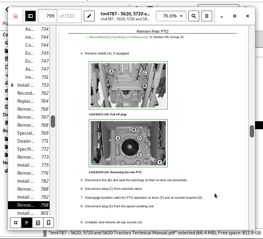
Remove Rear PTO
Install Rear PTO
Remove Front PTO
Install Front PTO
Group 05: U-Jointed Shafts and Torsion Damper
Summary of References (U-Jointed Shafts and Torsion Damper)
Special Tools
Use of Special Tool KJD10426
Specifications
Remove U.j. Shaft (Front-Wheel Drive)
Install U.j. Shaft (Front-Wheel Drive)
Disassemble U.j. Shaft (Front-Wheel Drive)
Assemble U.j. Shaft (Front-Wheel Drive)
Remove U.j. Shaft (Engine)
Install U.j. Shaft (Engine)
Remove Torsion Damper
Install Torsion Damper
Change Torsion Damper Bearings
Group 10: Front-Wheel Drive Clutch
Front-Wheel Drive Clutch — Reconditioning (Summary of References)
Special Tools
Other material
Specifications
Change Wheel Speed Sending Unit
Disassemble Front-Wheel Drive Clutch
Front-Wheel Drive Clutch — Exploded View
Assemble Front-Wheel Drive Clutch
Group 15: Differential
Differential — Reconditioning (Summary of References)
Specifications
Remove Differential Lock
Remove Differential
Disassemble Differential
Differential and Differential Lock — Exploded View
Assemble Differential
Install Differential
Disassemble Differential Lock
Assemble Differential Lock
Install Differential Lock
Group 20: Hydraulic Pump Drive
Hydraulic Pump Drive — Reconditioning (Summary of References)
Specifications
Remove Hydraulic Pump Drive
Hydraulic Pump Drive—Exploded View
Install Hydraulic Pump Drive
Group 25: Final Drives
Final Drives — Reconditioning (Summary of References)
Special or Essential Tools
Specifications
Disassemble Final Drives
Final Drives—Sectional View
Final Drives—Exploded View
Final Drives—Reconditioning the Planetary Carrier
Assemble Final Drives
Final Drives—Adjust Rolling Drag Torque
Group 30: Rear PTO
Rear PTO — Reconditioning (Summary of References)
Other Material
Specifications
Replace Output Shaft Seal Ring
Remove PTO Clutch
Exploded View of PTO Clutch
Recondition PTO Clutch
Install PTO Clutch
Disassemble PTO Drive Train
Recondition Output Shaft, 540/540E/1000 rpm
Recondition Output Shaft (540/540E rpm)—Exploded View
Recondition Countershaft (540/540E rpm and 540/540E/1000 rpm)
Assemble PTO Shifter (540/540E rpm and 540/540E/1000 rpm)
Assemble PTO Drive Train
Install Support and Adjust Taper Roller Bearings
Remove PTO Modulating Valve
Recondition PTO Modulating Valve
Install PTO Modulating Valve
Recondition Solenoid Valve
Replace PTO Speed Sending Unit
Change and Adjust Bowden Cable
Group 35: Front PTO
Front PTO — Reconditioning (Summary of References)
Specifications
General Repair Procedures
Clean Oil Screen
Replace Solenoid Valve
Remove Oil Pump
Exploded View of Oil Pump
Install the Oil Pump
Front PTO — Sectional View
Disassemble Front PTO
Disassemble Front PTO Clutch
Assemble Front PTO Clutch
Assemble Front PTO
Front PTO — Remove Constant-Velocity Joint from Drive Shaft
Front PTO — Install Constant-Velocity Joint on Drive Shaft
Remove Front PTO Oil Cooler
Install Front PTO Oil Cooler
Section 60: Steering and Brakes
Group 05: Hydrostatic Steering
Hydrostatic Steering (Summary of References)
Special or Essential Tools
Specifications
Preliminary Work
Disconnect/Connect Steering or Brake Hoses
Remove and Install Steering Valve
Exploded View of Steering Valve
Recondition Steering Wheel and Steering Column
Group 15: Brake Valve
Summary of References (Brake Valve)
Specifications
Remove and Install Brake Valve
Group 20: Rear Brakes
Summary of References (Rear Brakes)
Remove Rear Brakes
Install Rear Brake
Final Assembly
Bleeding the Brakes
Group 25: Handbrake
Handbrake (Summary of References)
Special or Essential Tools
Specifications
Remove Handbrake
Handbrake — Exploded View
Disassemble Handbrake
Assemble Handbrake
Install Handbrake
Handbrake — Components
Check and Adjust Handbrake
Group 30: Hydraulic Trailer Brake
Hydraulic Trailer Brake (Summary of References)
Special Tools
Specifications
Repair Instructions
Change Trailer Brake Valve
Clean the Trailer Brake Valve
Cleaning the Screen
Replace the Check Valve
Bleed Air from the Trailer Brake Valve
Check Hydraulic Trailer Brake Valve
Adjust Hydraulic Trailer Brake Valve
Group 35: Air Brakes
Summary of References (Air Brakes)
Special Tools
Specifications
Screw Union Installation
Change Compressor
Gaskets for the Compressor
Change Compressed Air Tank
Change Pressure Control Valve
Change Trailer Control Valve
Change Coupling Ends
Test Sequence
Check Air Brake System (Visual Checks)
Check System for Leaks
Check the "Supply" Coupling End
Check Dual-Line Brake
Check Single-Line Brake
Adjusting the Handbrake (with Air Brake System)
Section 70: Hydraulic System
Group 05: Controls
Hydraulic System — Controls (Summary of References)
Specifications
Selective Control Valves — Remove and Install the Actuating Elements
Selective Control Valves — Adjusting the Bowden Cable
Remove and Install the Multi-Function Lever
Adjust Multi-Function Lever
Group 10: Hydraulic Pump
Specifications
Remove Hydraulic Pump
Recondition Hydraulic Pump
Install Hydraulic Pump
Group 15: Valves
Reconditioning the Valves (PC Hydraulic System) — Summary of References
Special Tools
Specifications
Hydraulic System — General Instructions on Safety and Repair
Direct Control of Rockshaft
Remove and Install Rockshaft Valve
Recondition the Hitch Valve
Rockshaft Valve — Depth to Which Raising and Lowering Valves are Screwed In
Rockshaft Valve — Removing and Installing the Stepper Motor
Rockshaft Valve — Centering the Stepper Motor
Remove and Install Priority Valve
Recondition the Priority Valve
Remove and Install By-Pass Valve
Group 20: Hitch
Hitch — (Summary of References)
Special or Essential Tools
Self-Manufactured Special Tools
Other Material
Specifications
Rockshaft — Removing and Installing the Position Sensor and Toothed Segment
Remove and Install Rockshaft Housing
Removal and installation
Remove Rockshaft Cylinders
Install Rockshaft Cylinders
Remove and Install Draft Sensor and Draft Link Bearing Pins
Automatic Stabilizer Rod
Stabilizing Rod Bracket
Group 25: Selective Control Valves and Couplers
Reconditioning the Selective Control Valves and Couplers — Summary of References
Special Tools
Other Material
Specifications
Reconditioning the Selective Control Valves and Couplers — General Instructions on Safety and Reconditioning
SCV Identification
Arrangement of the Shuttle Valves
Remove and Install Selective Control Valves
Series 105 and 205 Selective Control Valves — Exploded View
Series 105 and 205 Selective Control Valves — Disassembly
Series 105 and 205 Selective Control Valves — Assembly
Series 305 Selective Control Valves — Exploded View
Series 305 Selective Control Valves — Disassembly
Series 305 Selective Control Valves — Assembly
Selective Control Valves — Reconditioning the Couplers
Selective Control Valves - Hydraulically Actuated Shut-Off Valves
Install a Front Loader
Section 80: Miscellaneous
Group 00: Removal and Installation of Components
Special or Essential Tools
Dealer-Fabricated Special Tools
Specifications
Remove Main Frame
Install Main Frame
Remove Front-Wheel Drive Axle
Install Front-Wheel Drive Axle
Remove Front Axle Support
Install Front Axle Support
Group 15: Front and Rear Wheels
Special or Essential Tools
Specifications
Front Wheels, Rear Wheels and Fenders—Reconditioning (Summary of References)
Remove Front and Rear Wheels
Recondition Front and Rear Wheels
Install Front and Rear Wheels
Pivoting (Front) Fender
Group 20: Trailer Mounting and Swinging Drawbar
Trailer Mounting and Swinging Drawbar - Reconditioning (Summary of References)
Specifications
Checking the Manually-Operated Hitch for Wear
Checking the Manually-Operated Hitch for Wear (Italy and Spain Only)
Checking the Remote Controlled Hitch for Wear
Checking the Tow-Hook for Wear
Check the Swinging Drawbar for Wear
Install the Center Link Support
Guide Rails for Height-Adjustable Trailer Hitch
Repair of Automatic Trailer Hitch
Remote Control for Automatic Trailer Hitch
Swinging Drawbar
Proper Use of Drawbar
Swinging Drawbar with Pick-Up Hitch
Group 30: Pick-Up Hitch
Pick-Up Hitch — Summary of References
Specifications
Other Material
Check Tow-Hook on Pick-Up Hitch for Wear
Install Pick-Up Hitch
Adjust the Lift Links
Check and Adjust the Retainer Spring
Recondition the Latch Housing
Repairing the Hydraulic Cylinder
Adjust the Guide Stop
Adjust the Locking Pin
Operational Check of Pick-Up Hitch
Group 40: Front Hitch
Front Hitch - Reconditioning (Summary of References)
Remove Front Hitch
Install Front Hitch
Remove and Install Bracket for Mowing Unit Suspension
Remove Lines and Hoses from Front Hitch without Multi-Valve
Install Lines and Hoses on Front Hitch without Multi-Valve
Remove Lines and Hoses from Front Hitch with Multi-Valve
Install Lines and Hoses on Front Hitch with Multi-Valve
Remove and Install Front Hitch Multi-Valve
Remove and Install Front Hitch Accumulator
Service the Front Hitch Accumulator
Group 50: Front Loader
Remove and Install the Mountings
Section 90: Operator's Cab
Group 00: Removal and Installation of Components
Operator's Cab, Removal and Installation of Components - Summary of References
Special Or Essential Tools
Specifications
Operator's Cab, Tilting or Removing and Installing
Tilt Operator's Cab Upward
Tilt Operator's Cab Downward
Disconnect/Connect Steering or Brake Hoses
Remove Operator's Cab
Install Operator's Cab
Check and Adjust Shift Units
Group 05: Controls and Instruments
Controls and Instruments (Summary of References)
Replacing Bulbs on the Instrument Unit
Replace Control Unit (EPC)
Replace Control Unit (BCU)
Replace Terminating Bus Resistors
Replace the Performance Monitor (PRF)
Replace the Basic Informator (BIF)
Group 10: Air-Condtioning System
Air-Conditioning System (Summary of References)
Special Tools
Specifications
Torques for Tightening Refrigerant Hoses
Safety At Work
Handling Refrigerant
In an Emergency
Safety Equipment
Storage of Refrigerant Containers
R134A Refrigerant
Important Note
Discharge the System
Evacuate the System
Fill with Refrigerant Oil
Instructions for Starting Up the DENSO Air-Conditioning Compressor
Charge the System
Leakage Test
Remove and Install Compressor
Checking Level in the Compressor
Disassemble Compressor Clutch
Checking Clutch Hub Clearance
Checking the Compressor Manifold
Remove and Install Condenser
Remove and Install Receiver-Drier
Remove and Install the Evaporator and Expansion Valve
Arrangement of Condensation Water Drain Hoses
Remove and Install Thermostat Switch
Adjust Thermostat Switch Bowden Cable
Remove and Install the High/Low Pressure Switch
Group 15: Heating System
Heating System (Summary of References)
Remove and Install Radiator
Remove and Install Fan Motors
Remove and Install Fan Motor Resistors
Remove and Install Heater Valve
Adjust Heater Valve Bowden Cable
Remove and Install Control Console for Ventilation System
Change Air Hoses in Ventilation System
Group 20: Seats
Specifications
Comfort Seat MSG83
Air Comfort Seat MSG95A-00, Lower Section
Passenger Seat, Exploded View
Group 25: Operator's Cab
Operator's Cab (Summary of References)
Cab Mounting Torques
Remove and Install Windshield
Remove and Install Rear Window
Remove and Install Sun Roof
Installing Door Lock
Remove and Install Cab Door
Remove Trim Panels from Switch Console
Remove Inner Roof Trim
Install Inner Roof Trim
Group 30: Parts for Electronic Hitch Control
Electronic Hitch Control (Summary of References)
Disconnecting Electrical Circuit
Service Information
Replace Control Unit (BCU)
Replace Hitch Control Operation Unit
Section 99: Special Tools (Dealer-Fabricated)
Group 05: Special Tools (Dealer-Fabricated)
DFLX1 - Adapter Strut
DFLX2 - Suspension Device for Perma Clutch II and Power Reverser Module
DFLX6 - Bushing
DFLX7 - Turning Device
DFLX10 - Holding Tool
DFLX32 - Holding Device
DFLX38 - Turning Device
DFRW2 - Needle Valve Test Hose Assembly
Group 10: Special Tools (available as spare parts)
AR52361 - Socket
D01019AA - Manually-Operated Hydraulic Pump
D01042AA – Load-Positioning Sling
FKM10002 or JT05470 - Pressure Test Kit
FKM10409 - Battery Tester
FKM10427 - Crimping Pliers
FKM10443 - Charging Valve
FKM10444 - Leak Detector
FKM10445 - Universal Pressure Test Kit
FKM10447 - Refrigerant Container (R134a; 920g; 750 ml)
FKM10470 - Pressure Measuring System (Stage 1)
FKM10471 - Pressure Measuring System (Stage 2)
FKM10472 - Flow Measurement System
FKM10472-4 - Temperature Sensor
FKM10482 - Pressure Test Kit
JDG19 – Special Mounting Brackets
JDG23 – Lifting Sling
JT02043 - Support Stand
JT02044 - Support Stand
JT02153 - Clamp-On Current Probe
JT03248 - Fitting
JT05723 – Medium-Duty Rear Tractor Splitting Stand
JT05791A - Multimeter
JT07115 - Pressure Test Kit
JT07211 - Support Stand
KJD10128 - Fitting
KJD10178C – Cab Tilting Device
KJD10194 - Pressure Test Kit
KJD10283 - Supplementary Kit
KJD10292 - Diagnostic Harness
KJD10352 - Restriction Fitting
KJD10495 - Hose Connector
KJD10501 - Disconnecting Tools (Kit)
RE200689 - Performance Monitor
RE37996 - Adjusting Tool
John Deere Tractors 5620, 5720, 5820 Diagnostic and Repair Service Manual (TM4787)
![]()