
John Deere Tractors 5300, 5400, 5500 Diagnostic and Repair Service Manual (TM4542)
Complete All Inclusive Technical Manual with electrical wiring diagrams for John Deere Tractors 5300, 5400, 5500, with all the shop information to maintain, diagnose, repair, service like professional mechanics (Diagnosis, Operation, Tests, Repair, Service, Troubleshooting).
John Deere Tractors 5300, 5400 and 5500 workshop technical diagnostics service repair test manual includes:
* Numbered table of contents easy to use so that you can find the information you need fast.
* Detailed sub-steps expand on repair procedure information
* Numbered instructions guide you through every repair procedure step by step.
* Troubleshooting and electrical service procedures are combined with detailed wiring diagrams for ease of use.
* Notes, cautions and warnings throughout each chapter pinpoint critical information.
* Bold figure number help you quickly match illustrations with instructions.
* Detailed illustrations, drawings and photos guide you through every procedure.
* Enlarged inset helps you identify and examine parts in detail.
tm4542 - 5300, 5400 and 5500 tractors Technical Manual.pdf
tm4542 - 5300, 5400 and 5500 tractors Technical Manual.epub
Total Pages: 1,546 pages
File Format: PDF/EPUB/MOBI/AZW (PC/Mac/Android/Kindle/iPhone/iPad; bookmarked, ToC, Searchable, Printable)
Language: English
MAIN SECTIONS
Foreword
Safety
Safety
General Specifications
Machine Specifications
Fuel, Lubricants and Coolant
Serial Number Locations
Engine - Repair
Removal and Installation of Engine Components
Fuel and Air Intake Systems - Repair
Fuel System
Speed Control Linkage
Air Intake System
Electrical System - Repair
Battery, Starting Motor and Alternator
Switches and Sending Units
Wiring Harnesses
Power Train - Repair
Removal and Installation of Power Train Components
Clutch
Hi-Lo System (24/24-Speed Transmission)
Power Take-Off
Differential
Final Drives
Mechanical Front Wheel Drive
MFWD Clutch - 12/12-Speed Transmission
MFWD Clutch - 24/24-Speed Transmission
Transmission
Steering And Brake Systems - Repair
Steering System
Brake System
Hydraulic System - Repair
Hydraulic Pump and Filter
Rockshaft
Selective Control Valves
Miscellaneous - Repair
Front Axle (Without MFWD)
Front Wheel Bearings
Three-Point Hitch
Operator's Cab and Open Operator's Station - Repair
Removing and Installing the Operator's Cab
Removing and Installing the Open Operator's Station
Controls and Instruments
Air Conditioning System
Operators's Cab
Operator's Seat
Electrical System - Operation and Tests
Component Location
Theory of Operation
Diagnosis, Tests and Adjustments
Wiring Diagrams - 5300, 5400 and 5500 Tractors
Power Train - Operation and Tests
Component Location
Theory of Operation
Diagnosis, Tests and Adjustments
Steering and Brake Systems - Operation and Tests
Component Location
Theory of Operation
Diagnosis, Tests and Adjustments
Hydraulic System - Operation and Tests
Component Location
Theory of Operation
Diagnosis
Tests
Adjustments
Hydraulic System Schematics
Air Conditioning System- Operation and Tests
Component Location
Theory of Operation
Diagnosis, Tests and Adjustments
Special Tools - Self-Manufactured
Manufacturing the Tools
tm4542 - 5300, 5400 and 5500 tractors
Table of Contents
Foreword
Section 05: Safety
Group 05: Safety
Recognize Safety Information
Understand Signal Words
“Important” Information
“Note” Information
Follow Safety Instructions
Handle Fluids Safely-Avoid Fires
Prevent Battery Explosions
Prepare for Emergencies
Prevent Acid Burns
Service Cooling System Safely
Avoid High-Pressure Fluids
Park Machine Safely
Support Machine Properly
Wear Protective Clothing
Work in Clean Area
Service Machines Safely
Work In Ventilated Area
Illuminate Work Area Safely
Replace Safety Signs
Use Proper Lifting Equipment
Keep ROPS Installed Properly
Service Tires Safely
Avoid Harmful Asbestos Dust
Avoid Heating Near Pressurized Fluid Lines
Remove Paint Before Welding or Heating
Use Proper Tools
Dispose of Waste Properly
Use Safety Lights and Devices
Practice Safe Maintenance
Service Front-Wheel Drive Tractor Safely
Live With Safety
Section 10: General Specifications
Group 05: Machine Specifications
Machine Specifications (Specifications and design subject to change without notice.)
Metric Cap Screw Torque Values-Grade 7
Metric Bolt and Cap Screw Torque Values
Unified Inch Bolt and Cap Screw Torque Values
Group 10: Fuel, Lubricants and Coolant
Diesel Fuel
Storing Fuel
Do Not Use Galvanized Containers
Fill Fuel Tank
Diesel Engine Oil
Transmission-/Hydraulic- and Front Wheel Drive Axle Oil
Oil Filters
Mixing of Lubricants
Grease
Alternative and Synthetic Lubricants
Lubricant Storage
Diesel Engine Coolant
Operating in Warm Temperature Climates
Group 15: Serial Number Locations
Serial Number Plates
Product Identification Number Location
Engine Serial Number
Fuel Injection Pump Serial Number Location
Alternator Serial Number Location
Power Steering Valve Serial Number Location
Air Conditioning Compressor Serial Number Location
Transmission Serial Number Location
Front Axle (2WD) Serial Number Location
Front Wheel Drive Serial Number
Starter Serial Number Location
Section 20: Engine - Repair
Group 00: Removal and Installation of Engine Components
Engine Repair
Special or Essential Tools
Specifications
Remove Engine
Install Engine
Water Pump Repair
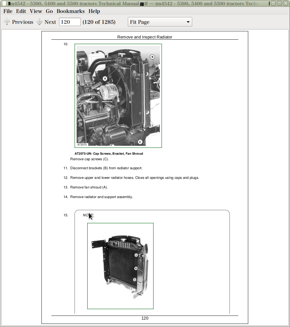
Remove and Inspect Radiator
Install Radiator
Remove and Install Oil Cooler
Replace Thermostat
Section 30: Fuel and Air Intake Systems - Repair
Group 05: Fuel System
Injection Pump, Nozzle and Governor Repair
Specifications
Remove, Inspect and Install Fuel Tank
Replace Fuel Filter
Remove and Install Fuel Filter / Primer Pump Assembly
Group 10: Speed Control Linkage
Remove and Install Speed Control Linkage
Inspect and Repair Speed Control Linkage
Throttle Lever Adjustment
Group 15: Air Intake System
Turbocharger Repair
Remove, Inspect and Install Air Cleaner Elements
Cleaning Primary Element
Washing Primary Element
Inspecting Element
Storing Element
Section 40: Electrical System - Repair
Group 05: Battery, Starting Motor and Alternator
Starting Motor Repair
Special or Essential Tools
Remove and Install Battery
Remove and Install Starting Motor
Alternator/Regulator Repair
Replace Alternator / Regulator
Group 10: Switches and Sending Units
Replace Air Filter Restriction Switch
Replace Coolant Temperature Sender
Replace Engine Speed Sensor
Replace Fuel Shut-Off Solenoid
Replace Engine Oil Pressure Switch
Replace Manifold Heater
Replace Key Switch
Replace Light Switch
Replace Hazard Warning Light Switch
Replace Turn Signal Controller
Replace Instrument Panel
Replace Rear PTO Switch
Replace Neutral Start Switch
Replace Parking Brake Switch
Replace Brake Pedal Switches
Replace Fuel Level Sender
Group 15: Wiring Harnesses
Replace Engine Wiring Harness
Replace Instrument Panel/Transmission Wiring Harness
Section 50: Power Train - Repair
Group 00: Removal and Installation of Power Train Components
Essential Tools
Specifications
Separate Engine From Clutch Housing (Tractors without Cab)
Install Engine to Clutch Housing (Tractors without Cab)
Separate Engine From Clutch Housing (Tractors with Cab)
Install Engine to Clutch Housing (Tractors with Cab)
Inspect and Repair Clutch Pedal and Linkage (Tractor without Cab)
Inspect and Repair Clutch Pedal and Linkage (Tractor with Cab)
Separate Clutch Housing from Transmission
Install Clutch Housing to Transmission
Replace Clutch Housing Seal (12/12 - Speed Transmission)
Replace Clutch Housing Seal (24/24 - Speed Transmission)
Group 05: Clutch
Essential Tools
Repair Specifications
Remove and Install Clutch Assembly
Disassemble and Inspect Clutch Assembly
Assemble Clutch
Traction Clutch Finger Adjustment
PTO Clutch Finger Adjustment
Remove and Inspect Clutch Release Mechanism
Install Clutch Release Mechanism
Group 10: Hi-Lo System (24/24-Speed Transmission)
Disassemble and Inspect Hi-Lo System
Assemble Hi-Lo System
Disassemble, Inspect and Assemble Hi-Lo Shift Shaft Assembly
Disassemble, Inspect and Assemble Hi-Lo Synchronizer
Disassemble, Inspect and Assemble Hi-Lo Drive Shaft
Disassemble, Inspect and Assemble Hi-Lo Reduction Shaft
Inspect and Repair Hi-Lo Shift Lever (For Tractors Without Cab)
Inspect and Repair Hi-Lo Shift Lever (For Tractors With Cab)
Group 15: Power Take-Off
Inspect and Repair Rear PTO Clutch Lever and Linkage (For Tractors without Cab)
Inspect and Repair Rear PTO Clutch Lever and Linkage (For Tractors with Cab)
Inspect and Repair Rear PTO Selector Lever and Linkage (For Tractors without Cab)
Inspect and Repair Rear PTO Selector Lever and Linkage (For Tractors with Cab)
Disassemble, Inspect and Assemble Rear PTO Engagement Control
Disassemble, Inspect and Assemble Rear PTO Engagement Sleeve (Models without Ground Speed PTO)
Disassemble, Inspect and Assemble Rear PTO Engagement Sleeve (Models with Ground Speed PTO)
Disassemble, Inspect and Assemble Rear PTO Drive Shaft Assembly (540rpm)
Disassemble, Inspect and Assemble Rear PTO Drive Shaft Assembly (540/540Erpm)and (540/1000rpm)
Disassemble, Inspect and Assemble Rear PTO Shift Leverage Assembly
Group 20: Differential
Essential Tools
Specifications
Remove and Install Differential Assembly
Disassemble, Inspect and Assemble Differential Assembly
Differential Bearing Pre-Load Adjustment (without Differential Drive Shaft)
Differential Backlash Adjustment
Inspect and Repair Differential Lock Pedal and Linkage
Remove, Inspect and Install Differential Lock Assembly
Group 25: Final Drives
Specifications
Remove and Install Final Drive Assembly
Remove and Inspect Planetary Drive Assembly (Tractors 5300 and 5400)
Remove and Inspect Planetary Drive Assembly (Tractors 5500)
Install Planetary Drive Assembly (Tractors 5300 and 5400)
Install Planetary Drive Assembly (Tractors 5500)
Remove, Inspect and Install Axle Shaft Assembly (Tractors 5300 and 5400)
Remove, Inspect and Install Axle Shaft Assembly (Tractors 5500)
Group 30: Mechanical Front Wheel Drive
Essential Tools
Specifications
Remove, Inspect and Install MFWD Drive Shaft
Remove and Install MFWD Axle Housing Assembly
Remove, Inspect and Install MFWD Axle Supports
Disassemble and Inspect MFWD Final Drive
Assemble MFWD Final Drive
Remove, Inspect and Install MFWD Swivel Housing
Remove, Inspect and Install MFWD Axle Shaft
Remove and Install MFWD Differential Carrier Assembly
Disassemble and Inspect MFWD Differential Carrier Assembly
Assemble MFWD Differential Carrier Assembly
Group 35: MFWD Clutch - 12/12-Speed Transmission
Repair Specifications
Inspect and Repair MFWD Lever
Remove and Install MFWD Clutch
Disassemble and Inspect MFWD Clutch
MFWD Clutch Cross Section
Assemble MFWD Clutch
Group 40: MFWD Clutch - 24/24-Speed Transmission
Specifications
Remove and Install Solenoid Control Valve
Inspect and Repair Solenoid Control Valve
Remove and Install MFWD Clutch
Disassemble and Inspect MFWD Clutch
MFWD Clutch Cross Section
Assemble MFWD Clutch
Group 45: Transmission
Special or Essential Tools
Specifications
Remove and Install Transmission
Inspect and Repair Gear and Range Shift Levers
Remove, Inspect and Install Range Shaft
Range Shaft End Play Adjustment
Remove Inspect and Install Primary and Reverse Shafts
Primary Shaft End Play Adjustment
Remove, Inspect and Install Pinion Shaft
Pinion Shaft Cone Point Adjustment
Pinion Bearing Pre-Load Adjustment
Remove, Inspect and Install Secondary Shaft
Secondary Shaft End Play Adjustment
Section 60: Steering And Brake Systems - Repair
Group 05: Steering System
Special or Essential Tools
Specifications
Remove and Install Steering Column and Valve
Disassemble and Inspect Steering Valve
Assemble Steering Valve
Remove and Install Steering Cylinder-2WD Axle
Disassemble, Inspect and Assemble Steering Cylinder-2WD Axle
Remove and Install Steering Cylinder-MFWD Axle
Disassemble, Inspect and Assemble Steering Cylinder-MFWD Axle
Remove, Inspect and Install Tie Rod Assembly-2WD Axle
Remove, Inspect and Install Tie Rod Assembly - MFWD Axle
Inspect and Replace Steering Hydraulic Lines
Inspect and Replace Steering Hydraulic Lines (For Tractors with Oil Cooler and Pipes)
Group 10: Brake System
Specifications
Remove and Install Brake Valve and Pedals
Disassemble and Inspect Brake Pedals
Disassemble Brake Valve
Brake Valve Cross Section
Assemble Brake Valve
Remove and Inspect Brakes
Install Brakes
Inspect and Replace Brake Hydraulic Lines
Remove, Inspect and Install Hydraulic Actuator
Remove, Inspect and Install Brake Linkage
Remove, Inspect and Install Parking Brake Lever
Remove, Inspect and Install Parking Brake Linkage
Remove and Inspect Trailer Brake Valve Lines
Install Trailer Brake Valve Lines
Section 70: Hydraulic System - Repair
Group 05: Hydraulic Pump and Filter
Special or Essential Tools
Specifications
Remove and Install Hydraulic Pump
Remove Hydraulic Pump External Components
Disassemble and Inspect Hydraulic Pump
Assemble Hydraulic Pump
Install Hydraulic Pump External Components
Remove and Install Hydraulic Filter/Manifold
Inspect and Replace Hydraulic Supply/Return Lines
Group 10: Rockshaft
Essential Tools
Specifications
Inspect and Repair Rockshaft Control Lever and Linkage
Remove, Inspect and Install Rockshaft Control Valve
Remove, Inspect and Install Sensing Linkage
Sensing Spring Adjustment
Safety and Relief Valve Adjustment
Remove and Install Rockshaft Case
Remove, Inspect and Install Rockshaft Lift Arms and Cylinder
Inspect and Repair Rockshaft Control Linkage
Rockshaft Sensitivity Adjustment
Rockshaft Position Control Lever Adjustment
Rockshaft Draft Control Lever Adjustment
Distributor Control Valve Adjustment
Group 15: Selective Control Valves
Remove and Install Selective Control Valves (SCV)
Disassemble, Inspect and Assemble Selective Control Valve (With Locking Position)
Disassemble, Inspect and Assemble Selective Control Valve (Double Acting SCV)
Disassemble, Inspect and Assemble Selective Control Valve (Single Acting SCV)
Disassemble, Inspect and Assemble Selective Control Valve (With Floating Position)
Inspect and Replace Hydraulic Hoses (SCV)
Section 80: Miscellaneous - Repair
Group 05: Front Axle (Without MFWD)
Special or Essential Tools
Specifications
Remove and Install Front Axle-2WD
Inspect and Replace Pivot Pin and Bushings-2WD Axle
Remove and Install Spindle Assembly-2WD Axle
Inspect and Replace Spindle Shaft Bushings-2WD Axle
Group 10: Front Wheel Bearings
Specifications
Inspect and Replace Front Wheel Bearings
Group 15: Three-Point Hitch
Inspect and Repair Draft Links
Inspect and Repair Adjustable Lift Link
Inspect and Repair Center Link
Section 90: Operator's Cab and Open Operator's Station - Repair
Group 00: Removing and Installing the Operator's Cab
Service Equipment and Tools
Specifications
Removing the Operator's Cab
Installing the Operator's Cab
Group 01: Removing and Installing the Open Operator's Station
Service Equipment and Tools
Specifications
Removing the Open Operator's Station
Installing the Open Operator's Station
Group 05: Controls and Instruments
Remove Molding of Control Lever (Tractor with Cab)
Install Molding of Control Lever
Remove Instrument Panel
Install Instrument Panel
Group 15: Air Conditioning System
Special or Essential Tools
Specifications
Torques for Tightening Refrigerant Hoses
Safety At Work
Handling Refrigerant
In An Emergency
Safety Equipment
Storage of Refrigerant Containers
R134A Refrigerant
Important
Discharging the System
Evacuating the System
Filling With Refrigerant Oil
Filling the System
Topping Up a Partly Discharged System
Replace Air Conditioning Receiver-Drier
Inspect Clean and Remove the Air Conditioning Condenser
Install Air Conditioning Condenser
Remove, Inspect and Install Air Conditioning Compressor
Remove and Install Air Conditioning Evaporator
Group 25: Operators's Cab
Service Equipment and Tools
Specifications
Remove Front Windshield
Install Front Windshield
Remove and Install Cab Door
Remove and Install Inner Handle
Cab Door, Exploded View
Remove and Install Rear Side Cab Windows
Rear Side Cab Windows, Exploded View
Remove Rear Window
Install Rear Window
Remove and Install Cab Recirculating/Fresh Air Filter
Group 30: Operator's Seat
Remove and Install Operator's Seat
Section 240: Electrical System - Operation and Tests
Group 05: Component Location
Component Location Information
Engine Electrical Components
Dashboard Electrical Components
Machine Electrical Components
Group 10: Theory of Operation
General Information
Fuse Box and Fuses
Cab Fuses, Size and Function
Main Fuse
Starting System Operation - Normal
Manifold Heater System Operation
Charging System Operation
Lighting System Operation - Turn Signals
Lighting System Operation - Hazard Warning Lights
Lighting System Operation - Parking And Instrument Lights
Lighting System Operation - Headlights and Instrument Lights
Lighting System Operation - Rear Work Light
Lighting System Operation - Front And Rear Work Lights (Cab Tractors Only)
Lighting System Operation - Beacon Lights
Lighting System Operation - Beacon Light Operation (Cab Tractors Only)
Instrument Panel System Operation - Tachometer
Instrument Panel System Operation - Fuel Gauge
Instrument Panel System Operation - Temperature Gauge
Instrument Panel System Operation - Hourmeter
Instrument Panel System Operation - PTO Warning System Operation
Instrument Panel System Operation - Air Filter Restriction Indicator Operation
Instrument Panel System Operation - Engine Oil Pressure Indicator Operation
Instrument Panel System Operation - Handbrake Indicator Operation
Horn Operation
7-Pin Trailer Connector Operation
3-Pin Optional Connector Operation
Pneumatic Seat Operation
Front Wheel Drive Operation
Brake Pedal Operation
Front And Rear Wiper/Washer Operation (Cab Tractors Only)
Dome Light Operation (Cab Tractors Only)
Radio Operation (Cab Tractors Only)
Blower Motor Operation (Cab Tractors Only)
Air Conditioning Operation (Cab Tractors Only)
Group 15: Diagnosis, Tests and Adjustments
Special or Essential Tools
Diagnostic Information
Wire Color Chart
Part Designations in Wiring Diagrams
Starting System Test Points
Manifold Heater Test Points
Charging System Test Points
Lighting System Test Points - Turn Signals
Lighting System Test Points - Warning Lights
Remaining Circuit
Lighting System Test Points - Headlights
Lighting System Test Points - Left Tail Light, Rear Work Light and Instrument Panel Light
Lighting System Test Points - Right Tail Light and License PlateLight
Stop Lights and Front Wheel Drive Circuit
Beacon Light Test Points
Horn Test Points
Trailer Connector Test Points
Three-Pin Connector Test Points
Instrument Panel Test Points - Fuel Gauge, Temperature Gauge, Tachometer
Instrument Panel Test Points - Hourmeter
Instrument Panel Test Points - PTO Warning System
Instrument Panel Test Points - Air Filter Restriction Indicator
Instrument Panel Test Points - Oil Pressure Indicator
Instrument Panel Test Points - Parking Brake
(Cab) Front and Rear Wiper/Washer Test Points
(Cab) Dome Light Test Points
(Cab) Radio Test Points
(Cab) Rear Work Light Test Points
(Cab) Front Work Light Test Points
(Cab) Blower Circuit Test Points
(Cab) Air Conditioning System Test Points
(Cab) Beacon Light Test Points
Battery Voltage and Specific Gravity Tests
Charge Battery
Battery Load Test
Starting Motor Amp Draw/RPM Test
Starting Motor No-Load Amp Draw/RPM Test
Alternator/Regulator Test
Starting Motor Solenoid Test
Key Switch Test
Parking Brake and Neutral Start Switch Test
PTO and Brake Pedal Switch Test
Light Switch Test
Turn Signal Controller Test
Hazard Warning Light Switch Test
Fuel Shut-Off Solenoid Valve Test
Group 20: Wiring Diagrams - 5300, 5400 and 5500 Tractors
Legend for 5300, 5400 and 5500 Tractors Wiring Diagram
Wiring Diagram for 5300, 5400 and 5500 Tractors
Wiring Diagram for 5300, 5400 and 5500 Cab Tractors
Section 250: Power Train - Operation and Tests
Group 05: Component Location
Component Location Information
Power Train Components
Traction and PTO Clutch Components
Transmission Components - 12/12 Speed Transmission
Transmission Components - 24/24 Speed Transmission
Final Drive Components
Rear PTO Components - 540 RPM
Rear PTO Components - 540/540E and 540/1000 RPM
Group 10: Theory of Operation
Theory of Operation Information
Clutch Operation - Traction Clutch Engaged and PTO Clutch Disengaged
Clutch Operation - Traction and PTO Clutch Engaged
Clutch Operation - Traction Clutch Disengaged and PTO Clutch Engaged
Transmission Power Flow - High-Low Splitter
Transmission Synchronizer Operation - High Low Splitter
Transmission Power Flow - Reverse Gears
Transmission Power Flow - Forward Gears
Transmission Synchronizer Operation - Reverse, Forward, 1st, 2nd, 3rd and 4th Gear
Transmission Power Flow - Range Shift
Rear PTO Operation
Differential Power Flow
Differential Lock Operation
Final Drive Operation
Mechanical Front Wheel Drive (MFWD) Operation - 12/12 Speed Transmission
Mechanical Front Wheel Drive (MFWD) Operation - 24/24 Speed Transmission
Group 15: Diagnosis, Tests and Adjustments
Diagnostic Information
Major Transmission Check
Traction Clutch Slips
Traction Clutch Dragging
Traction Clutch Does Not Engage
Traction Clutch Grabs
Traction Clutch Squeaks
Traction Clutch Does Not Release
Traction Clutch Chatters
Traction Clutch Rattles
Traction Clutch Engagement is Noisy
Excessive Vibration in Traction Clutch
Clutch Pedal Does Not Return
Clutch Pedal Loose
Clutch Pedal Pulsates
Jerky or Rough Transmission of Power
Low Transmission Oil Level (Excessive Oil Leakage)
Gears Clash, Shift Hard, or Will Not Engage
Two Speeds Engage Together
Transmission Will Not Stay in Gear
Transmission Noisy
PTO Noisy
PTO Hard to Engage
PTO Will Not Operate
PTO Will Not Stay Engaged
Excessive Differential Noise
Differential Does Not Work
Differential Lock Does Not Work
Differential Chatters
Axle Noise
Axle Shaft Will Not Turn
MFWD Lever is Hard to Engage
MFWD Lever Will Not Stay in “On” Position
Noisy Front Wheel Drive Operation
Clutch Pedal Free Play Adjustment
PTO Clutch Lever Adjustment
Section 260: Steering and Brake Systems - Operation and Tests
Group 05: Component Location
General Information
Steering System Components
Brake System Components
Trailer Brake System Components
Group 10: Theory of Operation
Theory of Operation Information
Steering System Operation
Steering Valve Operation-Neutral and Manual Turning
Steering Valve Operation-Power Turning
Brake System Operation
Brake Valve Operation - Brake Pedal Depressed
Trailer Brake System Operation
Group 15: Diagnosis, Tests and Adjustments
Special or Essential Tools
Diagnostic Information
Steering System Operational Check
Steering System Diagnosis
Steering Sluggish or Loss of Steering
Brake System Operational Check
Brake System Diagnosis
Excessive Brake Pedal Leak-Down
Excessive Brake Chatter
Trailer Brake Valve Operational Check
Trailer Brake Valve Operational Check (Italian Version)
Trailer Brake Valve Trouble Shooting (Italian Version)
Trailer Brake Valve Trouble Shooting
Steering Pump Flow Test
Steering Valve Relief Test
Steering Cylinder Leakage Test
Steering Valve Leakage Test
Toe-In Check And Adjustment (Standard Axle)
Toe-In Check And Adjustment (MFWD Axle)
Steering Stop Adjustment (MFWD Axle)
Brake Pedal Adjustment
Handbrake Adjustment
Bleed Brake System
Section 270: Hydraulic System - Operation and Tests
Group 05: Component Location
Component Location Information
Hydraulic System Components
Selective Control Valve Components
Group 10: Theory of Operation
Theory of Operation Information
Hydraulic System Operation
Hydraulic Filter Operation
Hydraulic Pump Operation
Oil Cooler Operation
Rockshaft Control Valve Operation - Neutral Position
Rockshaft Control Valve Operation - Raise Position
Rockshaft Control Valve Operation - Lower Position
Rockshaft Draft - Sensing Operation
Selective Control Valve Operation - Double Acting With Detent Position / Neutral Position
Selective Control Valve Operation - Double Acting With Detent Position / Supply Position
Selective Control Valve Operation - Double Acting With Detent Position / Return Position
Selective Control Valve Operation - Double Acting With Detent Position / Float Position
Selective Control Valve Operation - Single Acting / Neutral Position
Selective Control Valve Operation - Single Acting / Supply Position
Selective Control Valve Operation - Single Acting / Return Position
Double-Acting Sleeve Coupler Operation
Group 15: Diagnosis
Safety Precautions
Special or Essential Tools
Diagnostic Information
Hydraulic Oil Warm-Up Procedure
Hydraulic System Major Test
Hydraulic System Diagnosis
Insufficient Pump Delivery
Hydraulic Functions Too Slow
Excessive Pump Pressure
Slow Hydraulic Pump Response
Excessive Pump Noise During Operation
Rockshaft Does Not Lift or Lifts Slowly
Rockshaft Does Not Lower or Lowers Slowly
Neutral Position Unstable, Rockshaft Drops After Engine Shut-Down
SCV Control Lever Does Not Return to Neutral Position
SCV Does Not Return to Neutral Position - SCV With Detent Position
SCV Does Not Remain In Detent Position - SCV With Detent Position
Remote Cylinder Does Not Extend or Retract
Remote Cylinder Settles Under Load
Remote Cylinder Operates Too Fast or Too Slow
Group 20: Tests
Special or Essential Tools
Hydraulic System Tests-With SCV
Hydraulic System Tests
Pump Flow Test
SCV Relief Valve Test
SCV Leakage Test
Rockshaft Lift Cycle Test
Group 25: Adjustments
Special or Essential Tools
Rockshaft Control Lever Friction Adjustment
Rockshaft Sensitivity Adjustment
Rockshaft Position Control Adjustment
Rockshaft Draft Control Adjustment
Rockshaft Safety and Relief Valves Adjustment
SCV Relief Valve Adjustment
Group 30: Hydraulic System Schematics
Hydraulic Symbols
Legend for Hydraulic System Schematic-Steering, MFWD and Brake
Hydraulic System Schematic-Steering, MFWD and Brake
Legend for Hydraulic System Schematic-SCV and Rockshaft
Hydraulic System Schematic-SCV and Rockshaft
Section 290: Air Conditioning System- Operation and Tests
Group 05: Component Location
General Information
Air Conditioning System Components
Group 10: Theory of Operation
Theory of Operation Information
Principle of Heat Exchange
R134A Refrigerant
Air Conditioning System Operation
Compressor
Condenser
Receiver-Dryer
Expansion Valve
Group 15: Diagnosis, Tests and Adjustments
Safety Equipment
In an Emergency
Storage of Refrigerant Containers
R134A Refrigerant
Important Note
Special or Essential Tools
Special Tools
Diagnostic Information
Air Conditioning System Diagnosis
Pressure Deviations
Air Conditioning System Trouble-Shooting
Failure Of Mechanical Type
Section 299: Special Tools - Self-Manufactured
Group 05: Manufacturing the Tools
Adapter
Cone Point Adjustment Tools
Draft Control Adjusting Tool
John Deere Tractors 5300, 5400, 5500 Diagnostic and Repair Service Manual (TM4542)
![]()