
John Deere Tractors 5400N & 5500N Diagnostic and Repair Service Manual (TM1585)
John Deere Tractors 5400N & 5500N Diagnostic and Repair Service Manual (TM1585)
tm1585 - 5400n and 5500n tractors diagnostic and repair technical manual.pdf
Complete All Inclusive Technical Manual with electrical wiring diagrams for John Deere Tractors 5400N, 5500N, with all the shop information to maintain, diagnostic, repair, service like professional mechanics (Diagnosis, Operation, Tests, Repair, Service, Troubleshooting).
John Deere Tractors 5400N and 5500N workshop technical service repair manual includes:
* Numbered table of contents easy to use so that you can find the information you need fast.
* Detailed sub-steps expand on repair procedure information
* Numbered instructions guide you through every repair procedure step by step.
* Troubleshooting and electrical service procedures are combined with detailed wiring diagrams for ease of use.
* Notes, cautions and warnings throughout each chapter pinpoint critical information.
* Bold figure number help you quickly match illustrations with instructions.
* Detailed illustrations, drawings and photos guide you through every procedure.
* Enlarged inset helps you identify and examine parts in detail.
Total Pages: 1,476 pages
File Format: PDF (bookmarked, ToC, Searchable, Printable, high quality)
Language: English
MAIN SECTIONS
Foreword
General Information
Safety
General Specifications
Fuel and Lubricants
Serial Number Locations
Features and Accessories
Engine Repair
Engine
Cooling System
Fuel and Air Repair
Fuel System
Air Intake System
Speed Control Linkage
Electrical Repair
Battery, Starter, and Alternator
Electrical System Components
Wiring Harness
Power Train Repair
Clutch Housing
Clutch Assembly
Synchronized Reverser
Transmission
Rear PTO Drive Shaft
Differential
Final Drives
Mechanical Front Wheel Drive
Creeper Assembly
Steering and Brake Repair
Steering Repair
Brake Repair
Hydraulic Repair
Hydraulic Pump and Filter
Hydraulic Oil Cooler
Rockshaft
Selective Control Valve (SCV)
Miscellaneous Repair
Front Axle-2WD
Wheels
Fenders
3-Point Hitch
Operator Station Repair
Seat and Support
ROLL-GARD™
Rear Bar
Cab Components
Air Conditioning System
Heating System
Operational Checkout Procedures
Operational Checkout Procedures
Engine Operation, Tests and Adjustments
Component Location
Theory of Operation
Diagnosis, Tests and Adjustments
Fuel/Air Operation, Tests and Adjustments
Component Location
Theory of Operation
Diagnosis, Tests and Adjustments
Electrical System Operation, Test and Adjust
Component Location
Theory of Operation
Diagnosis, Test and Adjust
Wiring Schematics
Power Train Operation, Tests & Adjustments
Component Location
Theory of Operation
Diagnosis, Tests and Adjustments
Steering and Brake Operation, Tests, and Adjustments
Component Location
Theory of Operation
Diagnosis, Tests, and Adjustments
Hydraulic System Operation, Tests, and Adjustments
Component Location
Theory of Operation
Diagnosis
Hydraulic Tests
Adjustments
Hydraulic Schematics
Operator Station
Component Location
Theory of Operation
Diagnosis, Tests, and Adjustments
Dealer Fabricated Tools
Dealer Fabricated Tools
tm1585 - 5400n and 5500n tractors diagnostic and repair technical manual
Table of Contents
Foreword
Section 10: General Information
Group 05: Safety
Recognize Safety Information
Handle Fluids Safely-Avoid Fires
Understand Signal Words
Follow Safety Instructions
Handle Fluids Safely-Avoid Fires
Prevent Battery Explosions
Prepare for Emergencies
Prevent Acid Burns
Service Cooling System Safely
Handle Chemical Products Safely
Avoid High-Pressure Fluids
Park Machine Safely
Support Machine Properly
Wear Protective Clothing
Work in Clean Area
Service Machines Safely
Work In Ventilated Area
Illuminate Work Area Safely
Replace Safety Signs
Use Proper Lifting Equipment
Keep ROPS Installed Properly
Service Tires Safely
Avoid Harmful Asbestos Dust
Avoid Heating Near Pressurized Fluid Lines
Remove Paint Before Welding or Heating
Use Proper Tools
Dispose of Waste Properly
Live With Safety
Group 10: General Specifications
Machine Specifications
SyncReverser™ Transmission Ground Speed Estimates
Creeper Transmission Ground Speed Estimates
Correction Factors for Other Tire Sizes
Service Recommendations for O-Ring Boss Fittings
Service Recommendations for Flat Face O-Ring Seal Fittings
Metric Cap Screw Torque Values-Grade 7
Metric Bolt and Cap Screw Torque Values
Unified Inch Bolt and Cap Screw Torque Values
Group 20: Fuel and Lubricants
Diesel Fuel Specifications
Storing Fuel
Do Not Use Galvanized Containers
Fill Fuel Tank
Diesel Engine Oil
Diesel Engine Coolant
Liquid Coolant Conditioner
Transmission and Hydraulic Oil
MFWD Gear Oil
Grease
Alternative and Synthetic Lubricants
Lubricant Storage
Group 25: Serial Number Locations
Serial Numbers
Product Identification Number Location
Engine Serial Number Location
Fuel Injection Pump Serial Number Location
Alternator Serial Number Location
Power Steering Valve Serial Number Location
Starter Serial Number Location
Transmission Serial Number Location
Front Axle (2WD) Serial Number Location
Mechanical Front Wheel Drive (MFWD) Serial Number Location
Air Conditioning Compressor Serial Number Location
Group 30: Features and Accessories
Features and Accessories
Standard Features
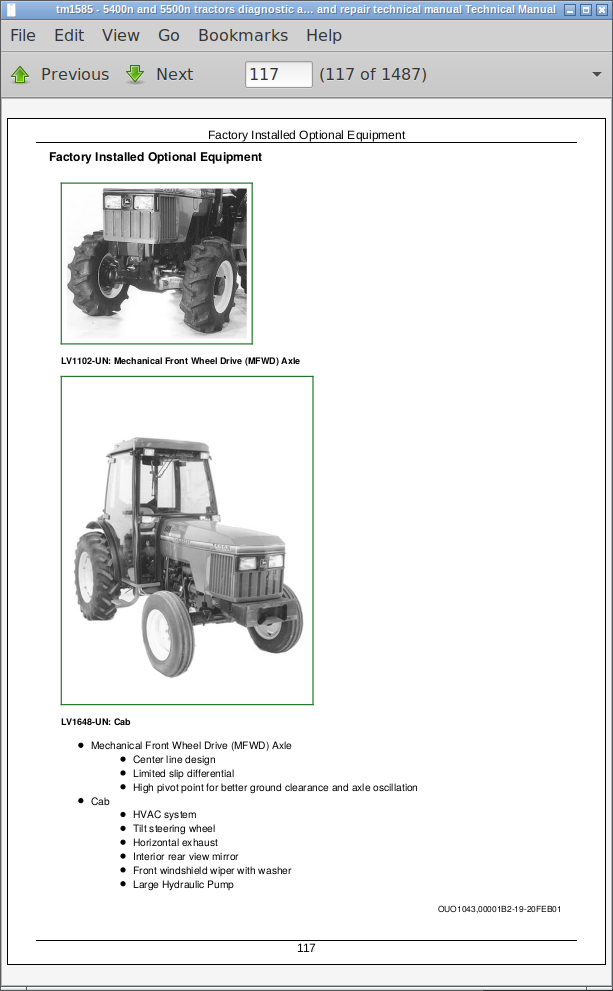
Factory Installed Optional Equipment
Field Installed Optional Kits and Accessories
Section 20: Engine Repair
Group 05: Engine
Specifications
John Deere Engine Repair-Use CTM8
Remove Engine-Tractors Without Cab
Install Engine-Tractors Without Cab
Remove Engine-Tractors With Cab
Install Engine-Tractors With Cab
Group 10: Cooling System
Engine Water Pump Repair-Use CTM8
Remove and Inspect Radiator-Tractors Without Cab
Install Radiator-Tractors Without Cab
Remove and Inspect Radiator-Tractors With Cab
Install Radiator-Tractors With Cab
Replace Thermostat-Early Models
Replace Thermostat-Later Models
Section 30: Fuel and Air Repair
Group 05: Fuel System
Specifications
Injection Pump, Nozzle and Governor Repair-Use CTM8
Remove, Inspect, and Install Fuel Tank-Tractors Without Cab
Remove, Inspect, and Install Fuel Tank-Tractors With Cab
Replace Fuel Filter
Remove and Install Fuel Filter/Primer Pump Assembly
Group 10: Air Intake System
Specifications
Turbocharger Repair-Use CTM8
Remove, Inspect, and Install Air Cleaner Elements-Early Models
Remove, Inspect, and Install Air Cleaner Elements-Later Model Tractors
Remove Turbocharger-5400N
Install Turbocharger-5400N
Remove Turbocharger-5500N
Install Turbocharger-5500N
Turbocharger Break-In
Group 15: Speed Control Linkage
Inspect and Repair Speed Control Linkage
Section 40: Electrical Repair
Group 05: Battery, Starter, and Alternator
Starter Repair-Use CTM77
Remove and Install Battery-Tractor Without Cab
Remove and Install Battery-Tractor With Cab
Remove and Install Starter-Early Models
Remove and Install Starter-Later Models
Replace Alternator/Regulator-40 Amp Without Cab
Replace Alternator/Regulator-60 Amp With Cab
Group 10: Electrical System Components
Other Material
Specifications
Service Equipment and Tools
Replace Air Filter Restriction Switch
Replace Coolant Temperature Sender
Replace Engine Speed Sensor
Replace Fuel Shut-Off Solenoid
Replace Engine Oil Pressure Switch
Replace Manifold Heater
Replace Manifold Heater Relay
Replace Key Switch
Replace Light Switch
Replace Turn Signal Controller
Replace Instrument Panel
Replace Rear PTO Switch
Replace PTO Seat Switch
Replace Neutral Start Switch
Replace Fuel Level Sender-Tractors Without Cab
Replace Fuel Level Sender-Tractors With Cab
Replace Park Brake Switch
Replace Radio (Optional Equipment)
Replace Speakers (Optional Equipment)
Replace Antenna (Optional Equipment)
Replace Blower Control Switch
Replace Air Conditioning Temperature Control Switch
Replace Front Wiper/Washer Control Switch
Replace Dome Light
Replace Dome Light Switch
Replace Convenience Outlet
Replace Cab Plug-In Relays
Replace Front Wiper Motor-Cab
Group 15: Wiring Harness
Essential Tools
Service Equipment and Tools
Service Parts Kits
Replace Connector Body-Blade Terminals
Replace WEATHER PACK WEATHER PACK is a trademark of Packard Electric. Connector
Install WEATHER PACK WEATHER PACK is a trademark of Packard Electric. Contact
Replace Front Wiring Harness-Tractors Without Cab
Replace Front Wiring Harness-Tractors With Cab
Replace Rear Wiring Harness-Tractors Without Cab
Replace Rear Wiring Harness-Tractors With Cab
Replace Cab Main Wiring Harness-Lights
Replace Cab Controls Wiring Harness-Main
Replace Cab Wiring Harness
Section 50: Power Train Repair
Group 05: Clutch Housing
Service Equipment and Tools
Other Material
Specifications
Separate Engine from Clutch Housing-Tractors Without Cab
Install Engine to Clutch Housing-Tractors Without Cab
Separate Engine from Clutch Housing-Tractors With Cab
Install Engine to Clutch Housing-Tractors With Cab
Inspect and Repair Clutch Pedal and Linkage
Group 10: Clutch Assembly
Essential Tools
Service Equipment and Tools
Other Material
Specifications
Service Parts Kits
Remove and Install Clutch Assembly
Disassemble and Inspect Clutch Assembly
Assemble Clutch Assembly
Traction Clutch Finger Adjustment
PTO Clutch Finger Adjustment
Remove and Inspect Clutch Release Mechanism and Shafts
Install Clutch Release Mechanism and Shafts
Group 15: Synchronized Reverser
Service Equipment and Tools
Specifications
Inspect and Repair F-N-R Selector Lever and Linkage-Tractors Without Cab
Inspect and Repair F-N-R Selector Lever and Linkage-Tractors With Cab
Inspect and Repair Synchronized Reverser
Group 20: Transmission
Service Equipment and Tools
Other Material
Specifications
Inspect and Repair Park Brake Lever
Separate Clutch Housing from Transmission
Install Clutch Housing to Transmission
Remove, Inspect, and Repair Gear Shift Lever
Remove, Inspect, and Repair Range Shift Lever
Remove Transmission
Disassemble and Inspect Transmission
Assemble and Install Transmission
Disassemble, Inspect and Assemble Shift Shaft Assemblies
Disassemble, Inspect, and Assemble Transmission Top Shaft
Disassemble, Inspect, and Assemble Range Reduction Shaft
Disassemble, Inspect, and Assemble Driven Shaft
Remove, Inspect, and Install MFWD and Range Gears
Remove, Inspect, and Repair Park Brake
Group 25: Rear PTO Drive Shaft
Service Equipment and Tools
Other Material
Specifications
Inspect and Repair Rear PTO Lever and Linkage
Inspect and Repair PTO 540/540E Lever and Linkage
Remove and Install Rear PTO Drive Shaft Assembly
Disassemble, Inspect and Assemble Rear PTO Drive Shaft Assembly
Group 30: Differential
Essential Tools
Service Equipment and Tools
Other Material
Specifications
Service Parts Kit
Remove and Install Differential Assembly
Disassemble, Inspect, and Assemble Differential Assembly
Remove and Inspect Differential Drive Shaft
Install Differential Drive Shaft
Differential Cone Point Adjustment
Differential Backlash Adjustment
Remove, Inspect, and Install Differential Lock Assembly
Group 35: Final Drives
Essential Tools
Service Equipment and Tools
Other Material
Specifications
Remove and Install Final Drive Assembly
Remove and Inspect Planetary Drive Assembly
Install Planetary Drive Assembly
Remove, Inspect, and Install Axle Shaft Assembly
Group 40: Mechanical Front Wheel Drive
Essential Tools
Service Equipment and Tools
Other Material
Specifications
Inspect and Repair MFWD Lever and Linkage
Remove and Install MFWD Drop Gearbox
Disassemble and Inspect MFWD Drop Gearbox
MFWD Drop Gearbox Cross Section
Assemble MFWD Drop Gearbox
Remove, Inspect, and Install MFWD Drive Shaft
Remove and Install MFWD Axle
Remove and Install MFWD Axle Pivot Pin and Pivot Bushings
Disassemble and Inspect MFWD Outer Drive
Assemble MFWD Outer Drive
Remove, Inspect, and Install MFWD Swivel Housing
Remove, Inspect, and Install MFWD Axle Shaft
Remove and Install MFWD Differential Carrier Assembly
Disassemble and Inspect MFWD Differential Carrier Assembly
Assemble MFWD Differential Carrier Assembly
Group 45: Creeper Assembly
Other Material
Specifications
Remove and Install Creeper Assembly
Disassemble, Inspect and Assemble Creeper Assembly
Section 60: Steering and Brake Repair
Group 05: Steering Repair
Other Material
Service Parts Kits
Specifications
Remove and Install Steering Column and Valve
Disassemble and Inspect Steering Valve
Assemble Steering Valve
Remove and Install Steering Cylinder-2WD Axle
Disassemble, Inspect and Assemble Steering Cylinder-2WD Axle
Disassemble, Inspect and Assemble Steering Cylinder-MFWD Axle
Remove, Inspect and Install Tie Rod Assembly-2WD Axle
Remove, Inspect and Install Tie Rod Assembly-MFWD Axle
Inspect and Replace Steering Hydraulic Lines-Without Oil Cooler
Inspect and Replace Steering Hydraulic Lines-With Oil Cooler
Group 10: Brake Repair
Service Equipment and Tools
Other Material
Specifications
Remove and Install Brake Valve
Disassemble and Inspect Brake Pedals and Valve
Brake Valve Cross Section
Assemble Brake Valve
Remove, Inspect and Install Brakes-Early Models
Remove, Inspect and Install Brakes-Later Models
Inspect and Replace Brake Hydraulic Lines
Section 70: Hydraulic Repair
Group 05: Hydraulic Pump and Filter
Service Equipment and Tools
Specifications
Service Parts Kits
Remove, Inspect and Install Hydraulic Oil Pick-Up Screen
Remove and Install Hydraulic Pump-5400N And 5500N
Remove Hydraulic Pump External Components-5400N And 5500N
Disassemble and Inspect Hydraulic Pump-5400N And 5500N
Assemble Hydraulic Pump-5400N And 5500N
Install Hydraulic Pump External Components-5400N And 5500N
Remove and Install Large Capacity Hydraulic Pump-5500N (Optional)
Remove Large Capacity Hydraulic Pump External Components-5500N (Optional)
Disassemble and Inspect Large Capacity Hydraulic Pump-5500N (Optional)
Assemble Large Capacity Hydraulic Pump-5500N (Optional)
Install Large Capacity Hydraulic Pump External Components-5500N (Optional)
Remove and Install Hydraulic Oil Filter and Manifold
Inspect and Replace Hydraulic Supply and Return Lines
Group 06: Hydraulic Oil Cooler
Remove, Inspect, and Install Hydraulic Oil Cooler
Group 10: Rockshaft
Service Equipment and Tools
Other Material
Specifications
Service Parts Kits
Inspect and Repair Rockshaft Control Lever Assembly-Early Models
Inspect and Repair Rockshaft Control Lever Assembly-Later Models
Inspect and Repair Rockshaft Control Linkage
Inspect and Repair Draft Sensing Support Assembly
Remove, Inspect and Install Secondary Relief Valve
Replace Rockshaft Surge Relief Valve
Remove, Inspect and Install Rate-of-Drop Valve
Replace Rockshaft Control Valve
Replace Rockshaft End Cover
Remove and Install Rockshaft Case
Remove, Inspect and Install Rockshaft Lift Arms
Remove, Inspect, and Install Rockshaft Piston and Cylinder
Group 15: Selective Control Valve (SCV)
Other Material
Specifications
Service Parts Kits
Remove and Install Selective Control Valve (SCV)
Disassemble, Inspect, and Assemble Selective Control Valve (SCV)
Inspect and Replace SCV Lines and Fittings
Inspect and Replace Power Beyond Lines and Fittings
Inspect and Replace Power Beyond Motor Control Lines and Fittings
Section 80: Miscellaneous Repair
Group 05: Front Axle-2WD
Service Equipment and Tools
Specifications
Remove and Install Front Axle-2WD
Inspect and Replace Pivot Pin and Bushings-2WD Axle
Remove and Install Spindle Assembly-2WD Axle
Inspect and Replace Spindle Shaft Bushings-2WD Axle
Group 10: Wheels
Service Equipment and Tools
Specifications
Inspect and Replace Front Wheel Bearings-2WD Axle
Group 15: Fenders
Specifications
Remove and Install Fenders
Group 20: 3-Point Hitch
Specifications
Inspect and Repair Draft Links
Inspect and Repair Adjustable Lift Links
Inspect and Repair Center Link
Remove and Install Drawbar and Support
Section 90: Operator Station Repair
Group 05: Seat and Support
Specifications
Remove and Install Seat and Support-Without Cab
Remove and Install Seat and Support-With Cab
Group 10: ROLL-GARDROLL-GARD is a trademark of Deere & Company.
Specifications
Remove and Install ROLL-GARD ROLL-GARD is a trademark of Deere & Company.
Group 15: Rear Bar
Specifications
Remove and Install Rear Bar-Without Cab
Remove and Install Rear Bar-With Cab
Group 20: Cab Components
Essential Tools
Other Material
Specifications
Remove Cab and Floor Plates
Install Cab and Floor Plates
Remove and Install Cab Outer Roof
Remove and Install Lower Front Windows and Support
Remove and Install Rear Side Cab Windows
Remove and Install Rear Cab Window
Remove and Install Front Windshield
Remove and Install Cab Doors
Remove, Inspect, and Install Cab Recirculating/Fresh Air Filter
Group 25: Air Conditioning System
Essential Tools
Service Equipment and Tools
Other Material
Service Parts Kits
Specifications
Hose and Tubing O-Ring Connection Torques
Recover/Recycle Air Conditioning Refrigerant
Replace Air Conditioning Receiver-Dryer
Remove, Inspect, and Install Air Conditioning Condenser
Remove, Inspect, and Install Air Conditioning Compressor
Test Volumetric Efficiency of Compressor
Test Compressor Shaft Seal Leakage
Disassemble and Assemble Compressor Clutch
Disassemble, Inspect, and Assemble Compressor
Check Compressor Clutch Hub Clearance
Inspect Compressor Manifold
Remove and Install Compressor Relief Valve
Remove Evaporator/Heater Core Housing
Install Evaporator/Heater Core Housing
Remove and Install Blower Motors
Remove, Test and Install Evaporator/Heater Core
Leak Test Evaporator/Heater Core
Install Evaporator/Heater Core
Service Expansion Valve
Expansion Valve Bench Test
Refrigerant Oil Information
Check Compressor Oil Charge
Determine Correct Refrigerant Oil Charge
Add Refrigerant Oil to System
System Information
Flush Air Conditioning System
Evacuate Air Conditioning System
Charge Air Conditioning System
Group 30: Heating System
Remove, Test and Install Heater Control Valve
Leak Test Heater Control Valve
Install Heater Control Valve
Section 210: Operational Checkout Procedures
Group 10: Operational Checkout Procedures
Operational Checkout Procedure Information
Engine Oil Level and Condition Check
Coolant Level and Condition Check
Transmission and Hydraulic Oil Check
Fan and Belt Check
Compressor Belt Check
Fuel System Check
Air Intake System Check
Electrical System Check
Hydraulic System Check
MFWD Oil Check
Indicator Lamps Check
Cab Blower Motor Check
A/C Compressor Clutch Check
Engine Start Check
Transmission Neutral Start Check
PTO Neutral Start Check
Engine Fast and Slow Idle Operation
Power Steering Check
Differential Lock Check
PTO Engagement Check
Clutch Check
Transmission Shift Check
Range Lever Shift Check
MFWD Drive Check
Park Brake Check
Rockshaft Check
Selective Control Valve Check
A/C System Operational Check
Cab Heater Valve Check
Miscellaneous Checks
Section 220: Engine Operation, Tests and Adjustments
Group 05: Component Location
Component Location Information
Engine External Components-Left Side
Engine External Components-Right Side
Group 10: Theory of Operation
Theory of Operation Information
Engine Lubrication System Operation
Engine Lubrication System Operation-Continued
Engine Cooling System Operation
Group 15: Diagnosis, Tests and Adjustments
Service Equipment and Tools
Specifications
Diagnostic Information
Engine Turns Over But Will Not Start or Starts Hard
Engine Runs Irregularly or Stalls Frequently
Engine Runs Rough
Engine Has Low Power
Engine Low Power-Continued
Engine Smokes-Black or Grey
Engine Smokes Excessively-White
Engine Uses Excess Fuel
Engine Has Excess Noise or Vibration
Engine Uses Excess Oil or Smokes Blue
Engine Has Low Oil Pressure
Engine Coolant Operating Temperature Incorrect
Oil in Coolant or Coolant in Oil
Radiator Bubble Test
Cooling System Test
Radiator Cap Pressure Test
Engine Oil Pressure Test
Cylinder Compression Pressure Test
Fuel Shut-Off Solenoid Check
Throttle Lever Adjustment
Slow Idle Adjustment
Fast Idle Adjustment
Injection Pump Timing Adjustment
Check and Adjust Valve Clearance
Fan/Alternator Drive Belt Adjustment
Compressor Drive Belt Adjustment
Turbocharger Boost Pressure Test
Bleed Fuel System
Section 230: Fuel/Air Operation, Tests and Adjustments
Group 05: Component Location
Component Location Information
Fuel System Components
Air Intake System Components
Group 10: Theory of Operation
Theory of Operation Information
Fuel System Operation
Fuel Filter/Priming Pump Operation
Fuel Injection Pump Operation
Fuel Injection Nozzle Operation
Air Intake System Operation
Turbocharger Operation
Group 15: Diagnosis, Tests and Adjustments
Diagnostic Information
Fuel/Air Diagnosis, Tests and Adjustments
Section 240: Electrical System Operation, Test and Adjust
Group 05: Component Location
Component Location Information
Engine Electrical Components
Dash Electrical Components
Machine Electrical Components-Tractor Without Cab
Machine Electrical Components-Tractor With Cab
Cab Control Panel and Electrical Components
Group 10: Theory of Operation
Theory of Operation Information
Fuse Block and Fuses-Early Tractors
Fuse Block and Fuses-Later Tractors Without Cab
Fuse Block and Fuses-Cab Tractors
Cab Fuse Block and Fuses
Relays
Starting System Operation-Normal
Starting System Operation-Bypass Attempt
Manifold Heater System Operation
Charging System Operation
Lighting System Operation-Turn Signals
Lighting System Operation-Warning Lights and Tail Light
Lighting System Operation-Headlights and Instrument Lights
Rear Flood Light Operation-Tractors Without Cab
Flood Light Operation-Tractor With Cab
Instrument Panel System Operation-Tachometer
Instrument Panel System Operation-Fuel Gauge
Instrument Panel System Operation-Temperature Gauge
Instrument Panel System Operation-Hour Meter
PTO Warning System Operation
Air Filter Restriction Indicator Operation
Optional Horn Operation
Accessory Relay and Optional Trailer Connection Operation
Blower Motor System Operation-Tractors With Cab
A/C Compressor System Operation-Tractors With Cab
Front Wiper/Washer System Operation-Tractors With Cab
Rear Wiper/Washer System Operation-Tractors With Cab
Dome Light Operation-Tractors With Cab
Group 15: Diagnosis, Test and Adjust
Diagnostic Information
Wire Color Chart
Starting System Test Points-Normal Operation
Starting System Test Points-Bypass Attempt
Manifold Heater Test Points
Charging System Test Points
Lighting System Test Points Left Turn Signals-Tractors Without Cab
Lighting System Test Points Right Turn Signals-Tractors Without Cab
Lighting System Test Points Left Turn Signals-Tractors With Cab
Lighting System Test Points Right Turn Signals-Tractors With Cab
Lighting System Test Points-Warning Lights (All Tractors)
Lighting System Test Points-Rear Flood Light (Tractors Without Cab)
Lighting System Test Points-Flood Lights (Tractors With Cab)
Lighting System Test Points-Dome Light (Tractors With Cab)
Lighting System Test Points-Tail Light
Lighting System Test Points-Headlights and Instrument Lights
Instrument Panel System Test Points-Tachometer
Instrument Panel System Test Points-Fuel Gauge
Instrument Panel System Test Points-Temperature Gauge
Instrument Panel System Test Points-Hour Meter
Instrument Panel System Test Points-Engine Oil Pressure Indicator
PTO Warning System Test Points
Air Filter Restriction Indicator Test Points
Optional Horn Test Points
Accessory Relay and Trailer Connector Test Points
Blower Motor Test Points (Tractors With Cab)
A/C Compressor Clutch Coil Test Points (Tractors With Cab)
Front Wiper/Washer Test Points (Tractors With Cab)
Battery Voltage & Specific Gravity Tests
Charge Battery
Battery Load Test
Starter Amp Draw/RPM Test
Starter No-Load Amp Draw/RPM Test
Alternator/Regulator Test
Starter Solenoid Test
Starter Relay Test
Key Switch Test
Plug-In Relay Test
Diode Pack Test
Fuse Test
Neutral Start Switch Test
PTO Switch Test
PTO Seat Switch Test
Light Switch Test
Turn Signal Controller Test
Fuel Shut-Off Solenoid Test
Blower Switch Test
Blower Motor Resistors
A/C Thermostatic Control Switch Test
Front Wiper/Washer Switch Test
Door Switch Test
Dome Light Switch Test
Group 20: Wiring Schematics
Schematic Information
Component Identification Table
5400N and 5500N Electrical Schematic and Legend-Early Tractors Without Cab
5400N and 5500N Electrical Schematic and Legend-Later Tractors Without Cab
5400N and 5500N Electrical Schematic and Legend-Later Tractors With Cab
Section 250: Power Train Operation, Tests & Adjustments
Group 05: Component Location
Component Location Information
Power Train Components
Clutch Components
Synchronized Reverser Components
Transmission Components
Park Brake Components
Final Drive Components
Rear PTO Components
Group 10: Theory of Operation
Theory of Operation Information
Clutch Operation
Synchronized Reverser Operation
Synchronized Reverser Power Flow
Transmission Lubrication System
Transmission Power Flow-Gear Shift
Transmission Gear Shift Synchronizer Operation
Transmission Power Flow-Range Shift
Park Brake Operation
Differential Power Flow
Differential Lock Operation
Final Drive Operation
Rear PTO Operation
Mechanical Front Wheel Drive (MFWD) Operation
Group 15: Diagnosis, Tests and Adjustments
Diagnostic Information
Isolate the Problem Area
Traction Clutch Slips
Traction Clutch Dragging
Traction Clutch Does Not Engage
Traction Clutch Grabs
Traction Clutch Squeaks
Traction Clutch Does Not Release
Traction Clutch Chatters
Traction Clutch Rattles
Traction Clutch Engagement Is Noisy
Excessive Vibration in Traction Clutch
Clutch Pedal Does Not Return
Clutch Pedal Loose
Clutch Pedal Pulsates
Jerky or Rough Transmission of Power
Low Transmission Oil Level (Excessive Oil Leakage)
Gears Clash, Shifts Hard, or Will Not Engage
Two Speeds Engage Together
Transmission Will Not Stay in Gear
Transmission Noisy
PTO Noisy
PTO Hard to Engage
PTO Will Not Operate
PTO Will Not Stay Engaged
Excessive Differential Noise
Differential Does Not Work
No Differential Lock
Differential Chatters
Axle Noise
Axle Shaft Will Not Turn
MFWD Lever is Hard to Engage
MFWD Lever Will Not Stay in “ON” Position
Noisy Front Wheel Drive Operation
Clutch Pedal Free Play Adjustment
PTO Clutch Lever Adjustment
Park Brake Band Adjustment
Park Brake Linkage Adjustment
PTO 540/540E Lever and Linkage Adjustment
Forward/Reverse Selector Lever Adjustment
Section 260: Steering and Brake Operation, Tests, and Adjustments
Group 05: Component Location
Component Location Information
Steering System Components
Steering System Components-5500N and All Cab Tractors
Brake System Components-Early Models
Brake System Components-Late Models
Group 10: Theory of Operation
Theory of Operation Information
Steering System Operation-5400N Without Cab
Steering System Operation-5500N and All Cab Tractors
Steering Valve Operation-Neutral and Manual Turning
Steering Valve Operation-Power Turning
Brake System Operation-Early Models
Brake System Operation-Late Models
Brake Valve Operation
Group 15: Diagnosis, Tests, and Adjustments
Diagnostic Information
Isolate the Problem-Steering System
Steering Sluggish or Loss of Steering
Isolate the Problem-Brakes
Excessive Brake Pedal Leak-Down
Excessive Brake Chatter
Steering Pump Flow Test
Steering Valve Relief Test
Steering Cylinder Leakage Test
Steering Valve Leakage Test
Toe-In Check and Adjustment-Standard 2WD Axle
Toe-In Check and Adjustment-MFWD Axle
Steering Stop Adjustment-2WD Axle
Steering Stop Adjustment-MFWD Axle
Brake Pedal Adjustment
Bleed Brake System
Section 270: Hydraulic System Operation, Tests, and Adjustments
Group 05: Component Location
Component Location Information
Hydraulic System Components
Selective Control Valve (SCV) Components
Group 10: Theory of Operation
Theory of Operation Information
Hydraulic System Operation
Hydraulic Filter Operation-5400N (Early Models)
Hydraulic Filter Operation-5400N and 5500N (Later Models)
Hydraulic Pump Operation
Rockshaft Control Valve Operation-Two Flow Regulator Valves
Rockshaft Control Valve Operation-Neutral Position
Rockshaft Control Valve Operation-Raise Position
Rockshaft Control Valve Operation-Lower Position
Surge Relief Valve Operation
Relief Valve Operation
Rate-of-Drop Valve Operation-Full Open
Rate-of-Drop Valve Operation-Partially Open
Rate-of-Drop Valve Operation-Full Closed
Rockshaft Draft-Sensing Operation
Selective Control Valve Operation-Neutral Position
Selective Control Valve Operation-Extend and Retract Positions
Selective Control Valve Operation-Boom Spool Float Position
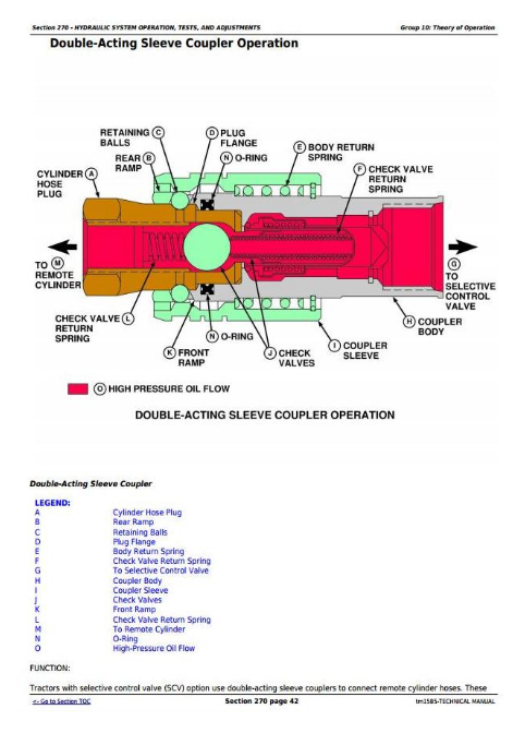
Double-Acting Sleeve Coupler Operation
Group 15: Diagnosis
Diagnostic Information
Preliminary Hydraulic System Inspection
Hydraulic Oil Warm-Up Procedure
Hydraulic System Components
Entire Hydraulic System Fails to Function/No Hydraulic Pump Output
Insufficient Pump Delivery
Hydraulic Functions Too Slow
Excessive Pump Pressure
Slow Hydraulic Pump Response
Excessive Pump Noise During Operation
Rockshaft Does Not Lift or Lifts Slowly
Rockshaft Does Not Lower or Lowers Slowly
Neutral Position Unstable, Rockshaft Drops after Engine Shut Down
SCV Control Lever Does Not Return to Neutral Position
Remote Cylinder Does Not Extend or Retract
Remote Cylinder Settles Under Load
Remote Cylinder Operates Too Fast or Too Slow
Group 20: Hydraulic Tests
Hydraulic System Tests
Pump Flow Test
Relief Valve Test
Selective Control Valve (SCV) Leakage Test
Rockshaft Leakage Test
Rockshaft Lift Cycle Test
Group 25: Adjustments
Rockshaft Control Lever Friction Adjustment
Rockshaft Draft-Sensing and Position-Sensing Linkage Adjustment
Rockshaft Draft-Sensing Feedback Linkage Adjustment
Relief Valve Adjustment
Group 30: Hydraulic Schematics
Hydraulic Circuit Symbols
Legend for Hydraulic Schematic-Early Models
Legend for Hydraulic Schematic-Later Models
Section 290: Operator Station
Group 05: Component Location
Air Conditioning System Components
Group 10: Theory of Operation
Refrigerant R134a
HVAC System Air Flow
Air Conditioning System Cycle
Compressor
Condenser
Receiver-Dryer
Expansion Valve
A/C Temperature Control Switch
Evaporator
Heater Temperature Control Knob
High and Low Pressure Switches
Group 15: Diagnosis, Tests, and Adjustments
Special or Essential Tools
Service Equipment and Tools
Other Material
Specifications
Section 299: Dealer Fabricated Tools
Group 00: Dealer Fabricated Tools
DFLV1A-Final Drive Turning Tool
DFRW20-Compressor Holding Fixture
DFRW83-Nozzle Assembly
JDG826-PTO Clutch Finger Height Gauge
JDG827-Traction Clutch Finger Height Gauge
JDG828-Traction Clutch Finger Height Adjustment Tool
![]()