
John Deere Tractors 5403, 5600, 5603, 5605, 5700, 5705 Diagnosis and Tests Service Technical Manual (TM8138)
Complete Diagnosis & Tests Technical Manual with electrical wiring diagrams for John Deere Tractors 5403, 5600, 5603, 5605, 5700, 5705, with all the shop information to maintain, diagnostic, service, and rebuild like professional mechanics.
John Deere South America Tractors 5403, 5600, 5603, 5605, 5700, 5705 workshop Diagnosis & Tests technical manual includes:
* Numbered table of contents easy to use so that you can find the information you need fast.
* Detailed sub-steps expand on repair procedure information
* Numbered instructions guide you through every repair procedure step by step.
* Troubleshooting and electrical service procedures are combined with detailed wiring diagrams for ease of use.
* Notes, cautions and warnings throughout each chapter pinpoint critical information.
* Bold figure number help you quickly match illustrations with instructions.
* Detailed illustrations, drawings and photos guide you through every procedure.
* Enlarged inset helps you identify and examine parts in detail.
tm8138 - 5403, 5600, 5603, 5605, 5700 and 5705 Tractors - Diagnostic Technical Manual.pdf
tm8138 - 5403, 5600, 5603, 5605, 5700 and 5705 Tractors - Diagnostic Technical Manual.epub
PRODUCT DETAILS:
Total Pages: 963 pages
File Format: PDF/EPUB/MOBI/AZW (PC/Mac/Android/Kindle/iPhone/iPad; bookmarked, ToC, Searchable, Printable)
Language: English
MAIN SECTIONS
Foreword
General Information
Safety
Engine System
Component Location
Theory of Operation
Operation, Tests and Adjustments
Electrical System (5600 and 5700)
How To Use Diagnostic Information
Electrical Components Test
Power Supply Overview
Engine Start Up
Engine Sensors
Engine Air Filter Sensor
PTO
Fuel Level
Horn
Lights
Connector Data
Electrical System (5403)
How To Use Diagnostic Information
Electrical Components Test
Power Supply Overview
Engine Start Up
Engine Sensors
Engine Air Filter Sensor
PTO
Fuel Level
Horn
Reverse Light and Backup Alarm
Lights
Connector Data
Electrical System (5603)
How To Use Diagnostic Information
Electrical Components Test
Power Supply Overview
Engine Start Up
Engine Sensors
Engine Air Filter Sensor
PTO
Fuel Level
Horn ( - 090000)
Horn (090001 - )
Reverse Light and Backup Alarm ( - 090000)
Reverse Light and Backup Alarm (090001 - )
Lights
Connector Data
Electrical System (5605 and 5705)
How To Use Diagnostic Information
Electrical Components Test
Power Supply Overview
Engine Start Up
Engine Sensors
Engine Air Filter Sensor
PTO
Fuel Level
Horn - 5605 ( - 090053) and 5705 ( - 0900125)
Horn - 5605 (090054 - ) and 5705 (0900126 - )
Reverse Light and Backup Alarm - 5605 ( - 090053) and 5705 ( - 090125)
Reverse Light and Backup Alarm - 5605 (090054 - ) and 5705 (090126 - )
Lights
Connector Data
Transmission Troubleshooting
Component Location - TSS Transmission
Theory of Operation - Carraro Clutch
Eaton Clutch and Transmission - Theory of Operation
Diagnostics, Tests and Adjustments - TSS Transmission
Brake and Steering
Location of Components
Theory of Operation - Brake and Steering
Steering and Brake - Diagnostics, Tests and Adjustments
Hydraulic System
Location of Components
Digital Temperature and Pressure Analyzer
Hydraulic System - Theory of Operation
Hydraulic System - Diagnostics
Hydraulic Test-Without SCV
Hydraulic Test-With SCV
Hydraulic Tests-General
Adjustments
Hydraulic Schematics
Others
tm8138 - 5403, 5600, 5603, 5605, 5700 and 5705 Tractors - Diagnostic Technical Manual
Table of Contents
Foreword
Section 10: General Information
Group 05: Safety
Recognize Safety Information
Understand Signal Words
Follow Safety Instructions
Handle Fluids Safely—Avoid Fires
Prevent Battery Explosions
Prepare for Emergencies
Prevent Acid Burns
Service Cooling System Safely
Handle Chemical Products Safely
Avoid High-Pressure Fluids
Park Machine Safely
Support Machine Adequately
Wear Protective Clothing
Work in Clean Area
Service Machines Safely
Work In Ventilated Area
Illuminate Work Area Safely
Replace Safety Signs
Use Proper Lifting Equipment
Keep ROPS Installed Properly
Service Tires Safely
Avoid Harmful Asbestos Dust
Avoid Heating Near Pressurized Fluid Lines
Remove Paint Before Welding or Heating
Use Proper Tools
Dispose of Waste Properly
Live With Safety
Section 220: Engine System
Group 05: Component Location
Information on Component Location
External Components of 4-Cylinder Engine—Left-Hand Side
External Components of 4-Cylinder Engine—Right-Hand Side
Group 10: Theory of Operation
Information on Theory of Operation
Operation of Engine Lubricating System
Operation of Engine Lubricating System—Continuation
Cooling System Operation—4-Cylinder Engine
Group 15: Operation, Tests and Adjustments
Check and Adjust Valve Clearance
Section 240: Electrical System (5600 and 5700)
Group 05: How To Use Diagnostic Information
Visual Inspection of Electrical System
Diagnostic Diagram and Information on Symbols in DiagramHow to use an Electrical Diagram
Electrical Diagram Symbols
Know the System
Ask the Operator
Group 10: Electrical Components Test
Battery Test
Recharging Battery
Important Recommendations about Batteries
Alternator Test
Battery Check
Test Starter Motor Solenoid
Starter Relay Test
Main Key Test
Relay Test
Diode Module Test
Fuse Test
PTO Sensor Test
Light Switch Test
Turn Signal Controller Test
Group 15A: Power Supply Overview
Theory of Operation
Diagram
Group 15B: Engine Start Up
Theory of Operation
Electrical Diagram
Diagnosing
Group 15C: Engine Sensors
Theory of Operation
Electrical Diagram
Diagnosing
Group 15D: Engine Air Filter Sensor
Theory of Operation
Electrical Diagram
Diagnosing
Group 15E: PTO
Theory of Operation
Electrical Diagram
Diagnosing
Group 15F: Fuel Level
Theory of Operation
Electrical Diagram
Diagnosing
Group 15G: Horn
Theory of Operation
Electrical Diagram
Diagnosing
Group 15H: Lights
Theory of Operation
Electrical Diagram
Diagnosing
Group 20: Connector Data
How to Use Connector Data
Wire Colors and Code Numbers
A01 - Fuse Box
A02 - Diode Module
A05 - Turn-Signal Switch
B01 - Neutral Start Switch
B02 - Air Filter Restriction Sensor Connector
B03 - Engine Oil Pressure Sensor
B04 - Engine Speed Sensor Connector
B05 - Coolant Temperature Sensor
B06 - Fuel Level Sensor
E01 - Left-Hand Headlight Connector
E02 - Right-Hand Headlight Connector
E04 - Front Right-Hand Clearance Light Connector
E05 - Front Left-Hand Clearance Light Connector
E06 - Rear Right-Hand Clearance Light Connector
E07 - Rear Left-Hand Clearance Light Connector
E08 - Front Right-Hand Turn Signal Light Connector
E09 - Front Left-Hand Turn Signal Connector
G02 - Alternator Connector
H03 - Horn Connector
KST - Starter Relay
K01 - Charge Relay 1
K02 - Charge Relay 2
K03 - Charge Relay 3
K04 - Brake Relay
K05 - Work Lights Relay
M01 - Starter Motor Terminals
S01 - Starter Switch
S02 - PTO Switch
S03 - Horn Switch
S05 - Right-Hand Brake Switch
S06 - Left-Hand Brake Switch
S09 - Lights Switch
X5 - Rear Clearance Light Grounding
X10 - Instrument Panel Connector
X11 - Connector between Front Wiring Harness and Rear Wiring Harness
X12 - Rear Right-Hand Position Light Connector
X13 - Rear Left-Hand Position Light
X26 - Starter Relay Ground
X29 - Ground Wire of Front Wiring Harness
X32 - Connector between Front Wiring Harness and Rear Wiring Harness
Y01 - Fuel Cut-Off Solenoid
Section 241: Electrical System (5403)
Group 05: How To Use Diagnostic Information
Visual Inspection of Electrical System
Diagnostic Diagram and Information on Symbols in DiagramHow to use an Electrical Diagram
Electrical Diagram Symbols
Know the System
Ask the Operator
Group 10: Electrical Components Test
Battery Test
Recharging Battery
Important Recommendations about Batteries
Alternator Test
Battery Check
Test Starter Motor Solenoid
Starter Relay Test
Main Key Test
Relay Test
Diode Module Test
Fuse Test
PTO Sensor Test
Light Switch Test
Turn Signal Controller Test
Group 15A: Power Supply Overview
Theory of Operation
Diagram
Group 15B: Engine Start Up
Theory of Operation
Electrical Diagram
Diagnosing
Group 15C: Engine Sensors
Theory of Operation
Electrical Diagram
Diagnosing
Group 15D: Engine Air Filter Sensor
Theory of Operation
Electrical Diagram
Diagnosing
Group 15E: PTO
Theory of Operation
Electrical Diagram
Diagnosing
Group 15F: Fuel Level
Theory of Operation
Electrical Diagram
Diagnosing
Group 15G: Horn
Theory of Operation
Electrical Diagram
Diagnosing
Group 15H: Reverse Light and Backup Alarm
Theory of Operation
Electrical Diagram
Diagnosing
Group 15I: Lights
Theory of Operation
Electrical Diagram
Diagnosing
Group 20: Connector Data
How to Use Connector Data
Wire Colors and Code Numbers
A01 - Fuse Box
A02 - Diode Module
A03 - Junction Box
A04 - Reverse Light and Backup Alarm
A05 - Turn-Signal Switch
B01 - Neutral Start Switch
B02 - Air Filter Restriction Sensor Connector
B03 - Engine Oil Pressure Sensor
B04 - Engine Speed Sensor Connector
B05 - Coolant Temperature Sensor
B06 - Fuel Level Sensor
E01 - Left-Hand Headlight Connector
E02 - Right-Hand Headlight Connector
E05 - Front Right-Hand Turn Signal Light Connector
E06 - Front Left-Hand Turn Signal Connector
E07 - Rear Clearance Light Connector
G02 - Denso Alternator Connector
G02 - Prestolite Alternator Connector
H03 - Horn Connector
KST - Starter Relay
K02 - Fuel Cut-Off Relay
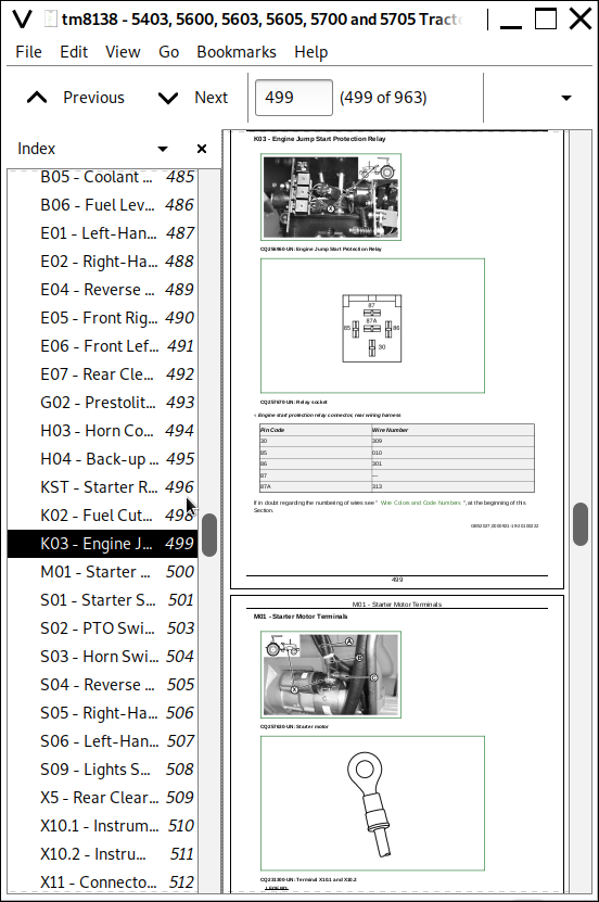
K03 - Engine Jump Start Protection Relay
M01 - Starter Motor Terminals
S01 - Starter Switch
S02 - PTO Switch
S03 - Horn Switch
S04 - Reverse Travel Switch
S05 - Right-Hand Brake Switch
S06 - Left-Hand Brake Switch
S09 - Lights Switch
X5 - Rear Clearance Light Grounding
X10.1 - Instrument Panel Connector
X10.2 - Instrument Panel Connector
X11 - Connector between Front Wiring Harness and Rear Wiring Harness
X26 - Rear Wiring Harness Ground
X27 - Horn Grounding
X28 - Back-Up Alarm Grounding
X29 - Ground Wire of Front Wiring Harness
X32 - Connector between Front Wiring Harness and Rear Wiring Harness
X33 - Horn Wiring Harness Connector
Y01 - Fuel Cut-Off Solenoid
Section 242: Electrical System (5603)
Group 05: How To Use Diagnostic Information
Visual Inspection of Electrical System
Diagnostic Diagram and Information on Symbols in DiagramHow to use an Electrical Diagram
Electrical Diagram Symbols
Know the System
Ask the Operator
Group 10: Electrical Components Test
Battery Test
Recharging Battery
Important Recommendations about Batteries
Alternator Test
Battery Check
Test Starter Motor Solenoid
Starter Relay Test
Main Key Test
Relay Test
Diode Module Test
Fuse Test
PTO Sensor Test
Light Switch Test
Turn Signal Controller Test
Group 15A: Power Supply Overview
Theory of Operation
Diagram
Group 15B: Engine Start Up
Theory of Operation
Electrical Diagram
Diagnosing
Group 15C: Engine Sensors
Theory of Operation
Electrical Diagram
Diagnosing
Group 15D: Engine Air Filter Sensor
Theory of Operation
Electrical Diagram
Diagnosing
Group 15E: PTO
Theory of Operation
Electrical Diagram
Diagnosing
Group 15F: Fuel Level
Theory of Operation
Electrical Diagram
Diagnosing
Group 15G: Horn ( - 090000)
Theory of Operation
Electrical Diagram
Diagnosing
Group 15H: Horn (090001 - )
Theory of Operation
Electrical Diagram
Diagnosing
Group 15I: Reverse Light and Backup Alarm ( - 090000)
Theory of Operation
Electrical Diagram
Diagnosing
Group 15J: Reverse Light and Backup Alarm (090001 - )
Theory of Operation
Electrical Diagram
Diagnosing
Group 15K: Lights
Theory of Operation
Electrical Diagram
Diagnosing
Group 20: Connector Data
How to Use Connector Data
Wire Colors and Code Numbers
A01 - Fuse Box
A02 - Diode Module
A03 - Junction Box
A04 - Reverse Light and Backup Alarm
A05 - Turn-Signal Switch
B01 - Neutral Start Switch
B02 - Air Filter Restriction Sensor Connector
B03 - Engine Oil Pressure Sensor
B04 - Engine Speed Sensor Connector
B05 - Coolant Temperature Sensor
B06 - Fuel Level Sensor
E01 - Left-Hand Headlight Connector
E02 - Right-Hand Headlight Connector
E04 - Reverse Light Connector
E05 - Front Right-Hand Turn Signal Light Connector
E06 - Front Left-Hand Turn Signal Connector
E07 - Rear Clearance Light Connector
G02 - Prestolite Alternator Connector
H03 - Horn Connector
H04 - Back-up Alarm Connector
KST - Starter Relay
K02 - Fuel Cut-Off Relay
K03 - Engine Jump Start Protection Relay
M01 - Starter Motor Terminals
S01 - Starter Switch
S02 - PTO Switch
S03 - Horn Switch
S04 - Reverse Travel Switch
S05 - Right-Hand Brake Switch
S06 - Left-Hand Brake Switch
S09 - Lights Switch
X5 - Rear Clearance Light Grounding
X10.1 - Instrument Panel Connector
X10.2 - Instrument Panel Connector
X11 - Connector Between Front Wiring Harness and Rear Wiring Harness ( - 090000)
X11 - Connector between Front Wiring Harness and Rear Wiring Harness (090001 - )
X26 - Rear Wiring Harness Ground
X27 - Horn Grounding
X28 - Back-Up Alarm Grounding
X29 - Ground Wire of Front Wiring Harness
X32 - Connector between Front Wiring Harness and Rear Wiring Harness
X33 - Horn Wiring Harness Connector
Y01 - Fuel Cut-Off Solenoid
Section 243: Electrical System (5605 and 5705)
Group 05: How To Use Diagnostic Information
Visual Inspection of Electrical System
Diagnostic Diagram and Information on Symbols in DiagramHow to use an Electrical Diagram
Electrical Diagram Symbols
Know the System
Ask the Operator
Group 10: Electrical Components Test
Battery Test
Recharging Battery
Important Recommendations about Batteries
Alternator Test
Battery Check
Test Starter Motor Solenoid
Starter Relay Test
Main Key Test
Relay Test
Diode Module Test
Fuse Test
PTO Sensor Test
Light Switch Test
Turn Signal Controller Test
Group 15A: Power Supply Overview
Theory of Operation
Diagram
Group 15B: Engine Start Up
Theory of Operation
Electrical Diagram
Diagnosing
Group 15C: Engine Sensors
Theory of Operation
Electrical Diagram
Diagnosing
Group 15D: Engine Air Filter Sensor
Theory of Operation
Electrical Diagram
Diagnosing
Group 15E: PTO
Theory of Operation
Electrical Diagram
Diagnosing
Group 15F: Fuel Level
Theory of Operation
Electrical Diagram
Diagnosing
Group 15G: Horn — 5605 ( - 090053) and 5705 ( - 0900125)
Theory of Operation
Electrical Diagram
Diagnosing
Group 15H: Horn — 5605 (090054 - ) and 5705 (0900126 - )
Theory of Operation
Electrical Diagram
Diagnosing
Group 15I: Reverse Light and Backup Alarm — 5605 ( - 090053) and 5705 ( - 090125)
Theory of Operation
Electrical Diagram
Diagnosing
Group 15J: Reverse Light and Backup Alarm — 5605 (090054 - ) and 5705 (090126 - )
Theory of Operation
Electrical Diagram
Diagnosing
Group 15K: Lights
Theory of Operation
Electrical Diagram
Diagnosing
Group 20: Connector Data
How to Use Connector Data
Wire Colors and Code Numbers
A01 - Fuse Box
A02 - Diode Module
A03 - Junction Box
A04 - Reverse Light and Backup Alarm
A05 - Turn-Signal Switch
B01 - Neutral Start Switch
B02 - Air Filter Restriction Sensor Connector
B03 - Engine Oil Pressure Sensor
B04 - Engine Speed Sensor Connector
B05 - Coolant Temperature Sensor
B06 - Fuel Level Sensor
E01 - Left-Hand Headlight Connector
E02 - Right-Hand Headlight Connector
E03 - Reverse Light Connector
E04 - Front Right-Hand Clearance Light Connector
E05 - Front Left-Hand Clearance Light Connector
E06 - Rear Right-Hand Clearance Light Connector
E07 - Rear Left-Hand Clearance Light Connector
E08 - Front Right-Hand Turn Signal Light Connector
E09 - Front Left-Hand Turn Signal Connector
G02 - Prestolite Alternator Connector
H03 - Horn Connector
H04 - Back-up Alarm Connector
M01 - Starter Motor Terminals
KST - Starter Relay
K02 - Fuel Cut-Off Relay
K03 - Engine Jump Start Protection Relay
K04 - Work Lights Relay
S01 - Starter Switch
S02 - PTO Switch
S03 - Horn Switch
S04 - Reverse Travel Switch
S05 - Right-Hand Brake Switch
S06 - Left-Hand Brake Switch
S09 - Lights Switch
X5 - Rear Clearance Light Grounding
X10.1 - Instrument Panel Connector
X10.2 - Instrument Panel Connector
X11 - Connector between Front Wiring Harness and Rear Wiring Harness—5605 ( - 090053) and 5705 ( - 090125)
X11 - Connector between Front Wiring Harness and Rear Wiring Harness—5605 (090054 - ) and 5705 (090126 - )
X12 - Rear Right-Hand Position Light Connector
X13 - Rear Left-Hand Position Light
X14 - Rear Right-Hand Clearance Light Connector
X15 - Rear Left-Hand Clearance Light Connector
X26 - Rear Wiring Harness Ground
X27 - Horn Grounding
X28 - Back-Up Alarm Grounding
X29 - Ground Wire of Front Wiring Harness
X32 - Connector between Front Wiring Harness and Rear Wiring Harness
X33 - Horn Wiring Harness Connector
Y01 - Fuel Cut-Off Solenoid
Section 250: Transmission Troubleshooting
Group 05: Component Location — TSS Transmission
Information Regarding the Location of Components
Drive Train Components
Clutch Components
Transmission Components—TSS
Final Drive Components
Rear PTO Components
Group 10 A: Theory of Operation — Carraro Clutch
Clutch Operation — Carraro
Clutch Operation — Continuation
Clutch Operation — Continuation
Group 10 B: Eaton Clutch and Transmission — Theory of Operation
Information on the Theory of Operation
Clutch Operation—CollarShift and SyncShuttle™ Transmissions
Transmission Lubrication System
CollarShift Transmission—Gear Shift Power Flow
SyncShuttle™ Transmission—Gear Shift Power Flow
SyncShuttle™ Transmission Synchronizer Operation—Reverse and 2nd Gear (Disk-and-Plate Type Synchronizer)
SyncShuttle™ Transmission Synchronizer Operation—1st and 3rd Gear (Cone-Type Synchronizer)
CollarShift Transmission—Shift Range Power Flow
PTO Power Flow
Rear PTO Operation
Differential Power Flow
Differential Power Flow
Differential Lock Operation
Differential Lock Operation
Final Drive Operation
Mechanical Front Wheel Drive (MFWD) Drop Gearbox Operation
Mechanical Front Wheel Drive (MFWD) Drop Gearbox Operation
Group 15: Diagnostics, Tests and Adjustments — TSS Transmission
Diagnostic Information
Isolate the Problem Area
Isolate the Problem Area — Continued
The Drive Clutch Slides
Drive Clutch Drag
Drive Clutch Does Not Engage
The Drive Clutch Sticks
Drive Clutch Creaking
Drive Clutch Does Not Release
Drive Clutch Vibrates
The Drive Clutch Creaks
The Drive Clutch Actuation Is Noisy
Excessive Vibration on the Drive Clutch
Clutch Pedal Does Not Return
Loose Clutch Pedal
Clutch Pedal Throbs
Power Transmission Abrupt or Leaping
Transmission Oil Level Low (Excessive Oil Leaking)
Gears Are Bumby, Are Hard to Engage or Do Not Engage
Two Gears Engage Together
Transmission Does Not Stay in Gear
Noisy Transmission
Noisy PTO
Hard to Engage PTO
PTO Does Not Operate
PTO does not Stay Activated
Excessive Differential Noise
Differential Does Not Operate
No Differential Lock
Differential Vibrates
Noisy Axle
Axle Does Not Turn
Difficulty in Engaging PTO Lever
MFWD Lever Does Not Stay in "ON" Position
Noisy MFWD Operation
Adjusting the Clutch Pedal Clearance
Adjusting the PTO Clutch Lever
Section 260: Brake and Steering
Group 05: Location of Components
Information about the Location of the Components
Steering System Components
Brake System Components
Group 10: Theory of Operation — Brake and Steering
Information About the Operation Theory
Steering System Operation
Steering Valve Operation — Manual Turn and Neutral
Steering Valve Operation — Power Assisted Turning
Brake System Operation
Brake Valve Operation
Brake Valve Operation — Continued
Brake Valve Operation — Resting Brake Pedal
Group 15: Steering and Brake — Diagnostics, Tests and Adjustments
Diagnostic Information for the Electrical System
Isolate the Problem — Steering System
Slow Steering or Loss of Steering
Isolate the Problem — Brakes
Excessive Brake Pedal Leak
Excessive Brake Vibration
Steering Pump Flow Test
Steering Valve Relief Test
Steering Cylinder Leakage Test
Steering Valve Leakage Test
Checking the Toe-In — Two-Wheel Drive
Adjusting the Toe-In — Two-Wheel Drive
Checking the Toe-In — Four-Wheel Drive
Adjusting the Toe-In — Four-Wheel Drive
Adjusting the Turning Angle of the Steering Backstop — Four-Wheel Drive
Brake Pedal Adjustment
Bleed Brake System
Section 270: Hydraulic System
Group 05: Location of Components
Information about the Location of the Components
Hydraulic System Components
Remote Control Valve Components
Group 05A: Digital Temperature and Pressure Analyzer
Norms of Safety
Test Applications
Digital Pressure Analyzer
Adjusting
Selecting the Function and Measuring Range
Ranges and Specifications
Group 10: Hydraulic System — Theory of Operation
Information About the Operation Theory
Hydraulic System Operation
Hydraulic Filter Operation
Hydraulic Pump Operation
Rockshaft Control Valve Operation—Two Flow Regulator Valves (Early Model Straddle Mount)
Rockshaft Control Valve Operation—Neutral Position (Early Model Straddle Mount)
Rockshaft Control Valve Operation—Raise Position (Early Model Straddle Mount)
Rockshaft Control Valve Operation—Lower Position (Early Model Straddle Mount)
Surge Relief Valve Operation
Main Relief Valve Operation—Straddle Mount Tractors
Main Relief Valve Operation—Isolated Open Operator Station and Cab Tractors
Rate-of-Drop Valve Operation—Full Open (Straddle Mount)
Rate-of-Drop Valve Operation—Full Open (Isolated Open Operator Station And Cab Tractors)
Rate-of-Drop Valve Operation—Partially Open (Straddle Mount)
Rate-of-Drop Valve Operation—Partially Open (Isolated Open Operator Station and Cab Tractors)
Rate-of-Drop Valve Operation—Full Closed (Straddle Mount)
Rate-of-Drop Valve Operation—Full Closed (Isolated Open Operator Station And Cab Tractors)
Hydraulic Hitch Depth Sensor Operation
SCV Operation—Straddle Mount Tractors (Neutral Position)
SCV Operation—Straddle Mount Tractors (Extend and Retract Positions)
Float SCV Operation—Straddle Mount Tractors (Float Position)
Regenerative SCV Operation—Straddle Mount Tractors (Regenerative Position)
SCV Operation—Isolated Open Operator Station and Cab Tractors (Neutral Position)
SCV Operation—Isolated Open Operator Station and Cab Tractors (Extend and Retract Positions)
Float SCV Operation—Isolated Open Operator Station and Cab Tractors (Float Position)
Regenerative SCV Operation—Isolated Open Operator Station and Cab Tractors (Regenerative Position)
Quick Disconnect Coupler Operation (Straddle Mount)
Quick Disconnect Coupler Operation (Cab and IOOS)
Group 15: Hydraulic System — Diagnostics
Diagnosis information
Preliminary Hydraulic System Inspection
Hydraulic Oil Warm-Up Procedure
Entire Hydraulic System Fails to Function/No Hydraulic Pump Output
Insufficient Pump Delivery
Hydraulic Functions Too Slow
Excessive Pump Pressure
Slow Hydraulic Pump Response
Excessive Pump Noise During Operation
Rockshaft Does Not Lift or Lifts Slowly
Rockshaft Does Not Lower or Lowers Slowly
Neutral Position Unstable, Rockshaft Drops after Engine Shut Down
SCV Control Valve Does NotReturn to Neutral Position — Third SCV
Remote Cylinder Does Not Extend or Retract
Remote Cylinder Settles Under Load
Remote Cylinder Operates Too Fast or Too Slow
Group 15A: Hydraulic Test—Without SCV
Hydraulic System Test—Without SCV (Step Platform Tractors)
Hydraulic System Test—Without SCV (Step Platform and Cab Tractors).
Pump Flow Test—Without SCV
Main Relief Valve Test—Without SCV (Straddle Mount Tractors)
Group 15B: Hydraulic Test—With SCV
Hydraulic System Test—With SCV (Step Platform Tractors)
Hydraulic System Test—With SCV (Step Platform Tractors)
Hydraulic System Test—With SCV (Step Platform and Cab Tractors).
Pump Flow Test—With SCV
Main Relief Valve Test—With SCV
SCV Leakage Test
Group 15C: Hydraulic Tests—General
Rockshaft Leakage Test—Straddle Mount
Rockshaft Leakage Test—Isolated Open Operator Station and Cab Tractors
Rockshaft Lift Cycle Test
Group 15D: Adjustments
Rockshaft Lever Friction Adjustment
Rockshaft Position-Sensing Feedback Linkage Adjustment
Adjusting hydraulic hitch depth sensor feedback link
Main Relief Valve Adjustment—Straddle Mount Tractors
Group 20: Hydraulic Schematics
Hydraulic Circuit Symbols
Hydraulic Schematic—Straddle Mount Tractors (Without SCV)
Hydraulic Schematic—Straddle Mount Tractors (With SCV)
Group 25: Others
Conversion Chart
Tool Suppliers
John Deere Tractors 5403, 5600, 5603, 5605, 5700, 5705 Diagnosis and Tests Service Technical Manual (TM8138)
![]()